Article

Cell-Dependent Mechanical Properties of Asymmetric Crosslinked Metallic Wire Mesh with Hybrid Patterns Based on Arbitrary Poisson’s Ratio

School of Mechanical Engineering and Automation, Fuzhou University, Fuzhou 350116, China
*
Author to whom correspondence should be addressed.
Symmetry 2023, 15(4), 941; https://doi.org/10.3390/sym15040941
Submission received: 28 March 2023 / Revised: 12 April 2023 / Accepted: 17 April 2023 / Published: 20 April 2023
(This article belongs to the Special Issue Symmetry Methods in Mechanics of Materials)

Abstract

:
Metallic wire mesh has gained attention as a potential material for lightweight aircraft structures, e.g., a metallic frame of morphing wings, due to its customizable mechanical properties associated with cell structures. However, the relationship between the pattern design of cell structures and the mechanical characteristics of metallic wire mesh remains unclear. The present work aims to investigate the mechanical behavior of asymmetric crosslinked metallic wire mesh with a hybrid Poisson’s ratio pattern, which has the potentials of arbitrary Poisson’s ratios. Two typical designs of cell arrangement for asymmetric crosslinked metallic wire mesh were proposed, namely negative Poisson’s ratio cells (NPRC) and positive Poisson’s ratio cells (PPRC). The in-plane Poisson’s ratio of asymmetric crosslinked metallic wire mesh was calculated based on the Euler beam theory. The effects of hybrid Poisson’s pattern and interwoven joint on mechanical properties, including macroscopic Poisson’s ratio and elastic bending recovery, were analyzed using numerical and experimental methods. The results demonstrate that the analytical Poisson’s ratio obtained from the proposed theoretical model agrees well with the simulation result. The hybrid structure which consisted of NPRC and PPRC could effectively control transverse shrinkage and become one of the most efficient potentials for promising structures with the arbitrary Poisson’s ratio phenomenon.

1. Introduction

The metallic wire mesh is typically produced by weaving interlinked wires using specific techniques in both vertical and horizontal directions. Being an organized porous structure, metallic wire mesh offers substantial benefits compared to conventional solid metals, such as having lightweight properties, a lower thermal conduction, and the design flexibility of cell patterns. The woven wire meshes with a variety of cell structures have demonstrated tremendous potential for engineering applications, including convective heat transfer structures [1,2,3], flexible rockfall protection [4,5,6], gradient cores of sandwich panels [7,8], impact-resistant expanded metal tubes [9,10] and reinforced elements of composite structures [11,12].
Recently, there has been a growing interest in various metal-woven structures, e.g., warp-knitted metal mesh fabric [13], textile cores [14], WBK (wire-woven bulk kagome) [15], metal rubber [16] and chain-link steel wire nets [17]. Typically, theoretical analyses and numerical methods are commonly used to investigate structure-related performances. Zhang et al. [18] proposed an analytical expression of the wire mesh structure and compared it to the numerical prediction of effective elastic constants obtained by the finite element method (FEM). They pointed out that it was possible to obtain reliable predictions using theoretical methods. However, accurately and numerically simulating the effective elastic parameters of metallic wire mesh is challenging due to uncertainties such as the uneven deformation of cell structure, complicated frictional processes, and nonlinear material behaviors. In order to solve the inaccurate numerical prediction and enormous costs, Albrecht et al. [17] developed a new discrete element model for chain-link steel wire nets to capture the nonlinear and anisotropic behaviors, as well as to improve numerical efficiency. Li et al. [19] proposed a fractal mechanics method for wire mesh to derive the stiffness of wire mesh reflectors in modeling mechanics applications. Ma et al. [20] investigated the influence of strain hardening of the parent material, impact velocity, initial curvature, and functional gradient on the compressive crushing properties of 3D double-U hierarchical lattices by compression experiments and finite element simulations. The results showed that the metallic 3D double-U auxetic structures could exhibit high stiffness, strength, toughness, and impact resistance with low relative density. In summary, combined analytical and numerical methods associated with the cell-dependent structure are essential for the analysis of structural material and its deformation mechanism.
Of particular importance is the mechanical characteristics of metallic wire mesh under complex loading conditions. Yang et al. [13] reported that warp-knitted metal mesh showed obvious anisotropic properties when subjected to uniaxial and biaxial stress loading conditions. Xue et al. [21] synthesized elastic-porous materials with metallic wire mesh (EPMWM) structures using entangling and weaving technologies and theoretically analyzed their mechanical and heat conduction properties under different loads. To enhance the energy absorption performance of wire mesh, Wu et al. [22] proposed a combined swelling and vacuum solid-phase sintering technology for the fabrication of a crocheted sintered mesh tube (CSMT), in which the key geometrical parameters, such as the diameter and the tube length, significantly affect the crushing mode and stability. Dong et al. [23] introduced buckling pattern into the straight-walled lattice structure. The quasi-static in-plane crushing test results clearly show that the initial peak force (IPF), the crushing force efficiency (CFE), the specific energy absorption (SEA) and the mean crushing force (MCF) can be substantially improved. Formisano et al. [24] investigated the mechanical behaviors and collapse mechanisms of innovative aluminum foam-based sandwich panels under quasi-static three-point bending. Xue et al. [25] explored the spring arm structure of square and double arrowhead lattice topology modalities. For existing lattice structures, the type with spring-arm connection mode may have the advantage of hyper-elastic deformation. Rana et al. [26] reported an investigation on missing-rib-design-based auxetic structures produced from braided composites. A new analytical model was proposed to predict Poisson’s ratio through a semi-empirical approach, which can well predict the auxetic behaviors of these structures but at very low or high strains. Some researchers have made positive efforts in structural design and performance control in terms of Poisson’s ratio analysis [27,28,29]. Although metallic wire mesh with various cell structures can be independently useful for engineering materials or be considered as one of the reinforced elements, few attempts have focused on investigating asymmetric crosslinked metallic wire mesh with a hybrid pattern structure and its cell-dependent mechanical characteristics.
In this work, the asymmetric crosslinked metallic wire mesh with a hybrid cell pattern is investigated based on an arbitrary Poisson’s ratio using theoretical, numerical, and experimental methods. First, theoretical modeling is performed to analyze the deformation of positive Poisson’s ratio cell (PPRC) and negative Poisson’s ratio cell (NPRC) structures based on a few basic assumptions. Second, the mechanical properties of asymmetric crosslinked metallic wire mesh structures with hybrid cell patterns are determined through uniaxial and three-point bending tests. Finally, the study analyzes and discusses the effect of wire interwoven joints on the in-plane distortion and elastic bending behavior of the asymmetric crosslinked metallic wire mesh.

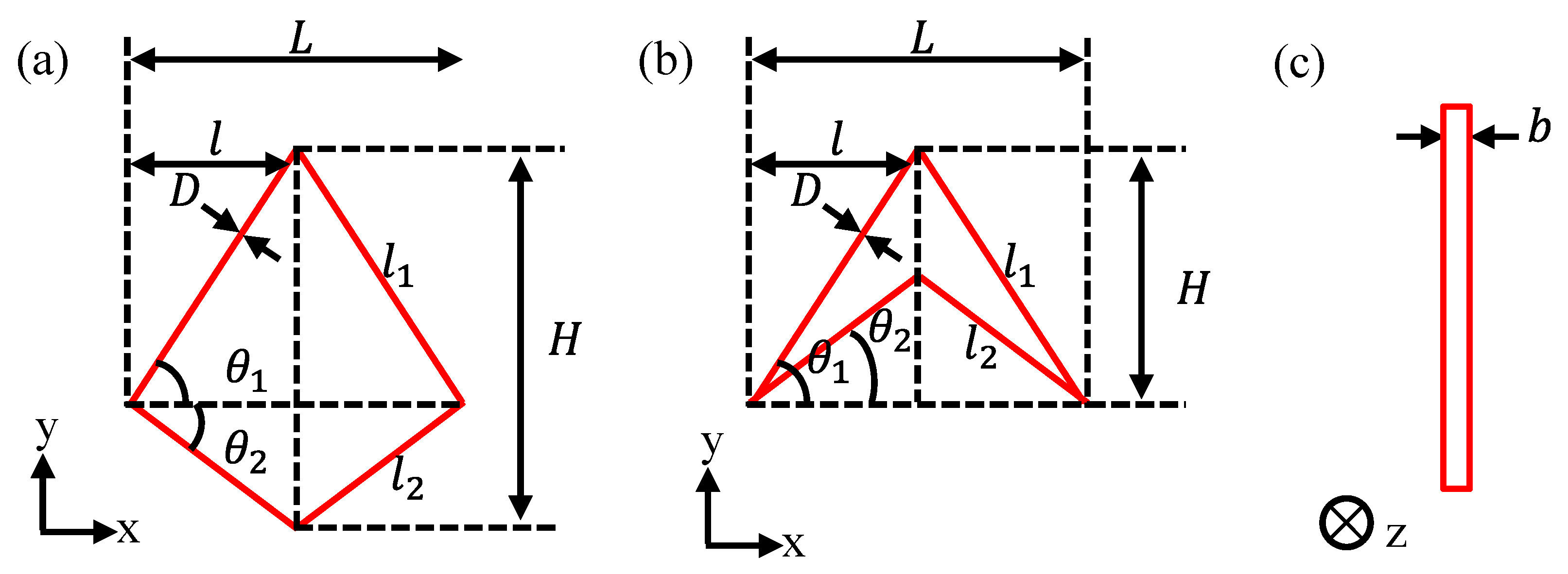
2. Theoretical Representation of Metallic Wire Mesh

The metallic wire mesh structure analyzed in this study exhibits strong plane or space distribution regularity. The representative elementary volumes (RVE) consist of two types, namely PPRC and NPRC, which are illustrated in Figure 1. Each simplified unit cell of the RVE is described by seven basic geometrical parameters: the length of the inclined member l1 (longer one) and l2 (shorter one), the x-axis projection length of the inclined members l, the cell thickness b, the angles between the inclined members and the horizontal line θ1 and θ2, and the cross-section diameter of the wire D.
Several assumptions are made regarding the theoretical model of the metallic wire mesh. Firstly, following homogenization theory, the simplified unit cell with effective Poisson’s ratio, under periodic boundary conditions, can represent the entire macroscopic structure without considering size and boundary effects. Secondly, the strains are low enough that obvious changes in geometry do not occur. Thirdly, the deformation in the thickness direction is not considered and the simplified unit cell is assumed to consist of uniformly slender beams. Finally, the axial and shear deformations are ignored as they are much lower than bending deformations.
A uniform remote stress (σ) is assumed to impose the PPRC, which corresponds to the vertical force 2PA = 2PC = 2lbσ applied at points A and C in Figure 2.
Because of its symmetry, only half of the PPRC structure (i.e., structure A-B-C) is considered and the horizontal displacement and rotation of A and C are constrained with the reaction force and moment being NA, MA, NC, and MC. Additionally, vertex B is entirely fixed. The vertices A and C have identical deformation in horizontal displacement but can move freely along vertical displacement. Therefore, considering the special geometric features and deformation compatibility conditions, the following equilibrium equations can be obtained:
δ P A N A P A + δ M A N A M A + δ N A N A N A = δ P C N C P C + δ M C N C M C + δ N C N C N C
δ P A M A P A + δ M A M A M A + δ N A M A N A = 0
δ P C M C P C + δ M C M C M C + δ N C M C N C = 0
where δij represents the j-th displacement component due to the force in i direction. The strain field in the x and y direction can be derived as:
ε y = u y A + u y B l ( tan θ 1 + tan θ 2 )
ε x = u x A l
Accordingly, the equivalent Poisson’s ratio of PPRC structure in the y can be expressed as:
v x y = ε x ε y = tan θ 1 tan θ 2
when the NPRC structure is stressed in the y direction, the vertical force applied at points A and C is 2P′A = 2P′C = 2lbσ. The loading diagram is shown in Figure 3. Similarly, the equivalent Poisson’s ratio of NPRC structure in the y can be expressed as:
v x y = ε x ε y = cot θ 1 cot θ 2
A detailed derivation is provided in Appendix A.

3. Materials and Methods

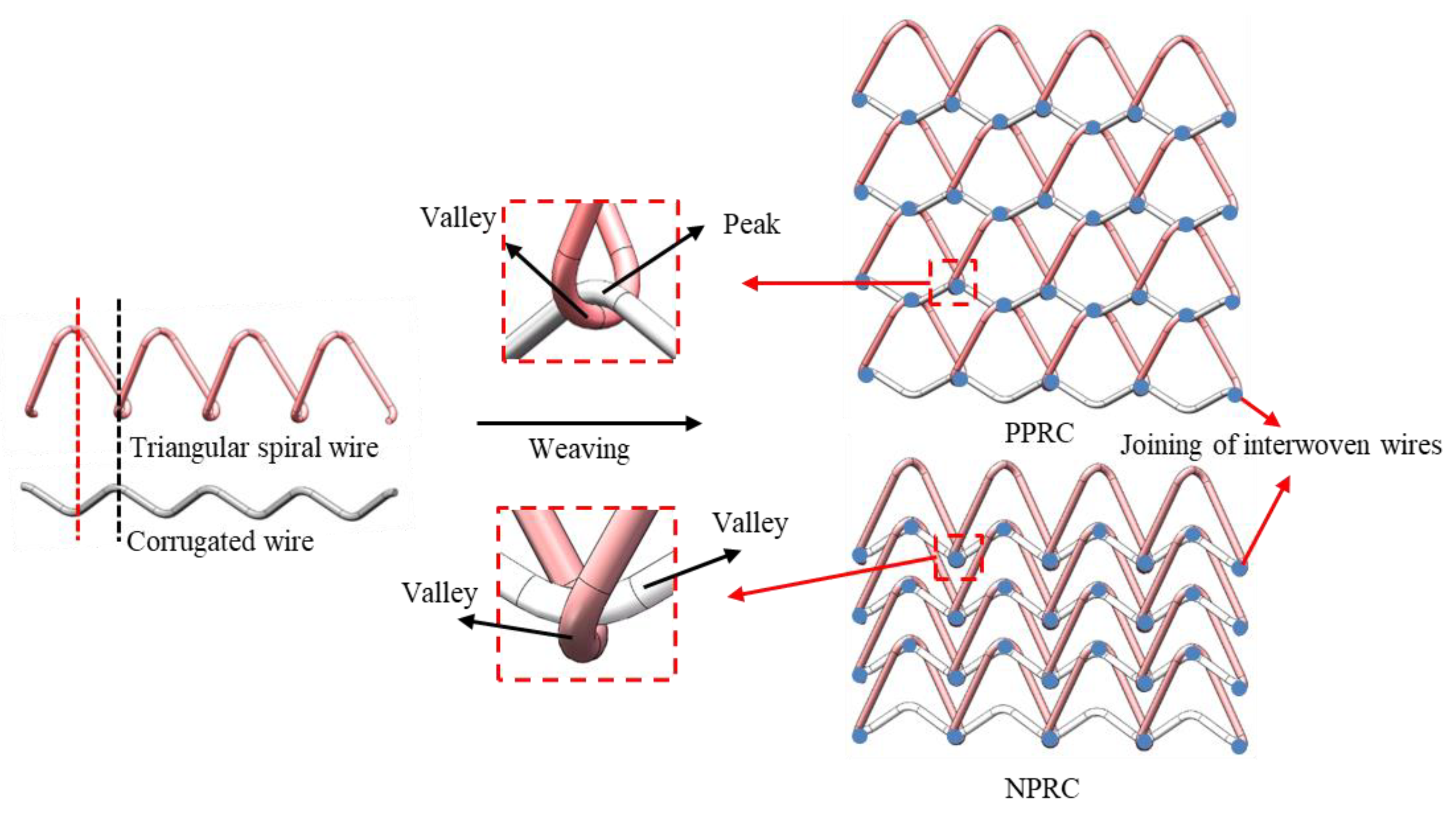
3.1. Structural Design of Asymmetric Crosslinked Metallic Wire Mesh

The asymmetric crosslinked metallic wire mesh structure consists of triangular spiral and corrugated wire, as shown in Figure 4. The peaks of the components are represented by black dotted lines, with one line corresponding to the valley of the triangular spiral wire and the other to the peak of the corrugated wire. The red dashed line corresponds to the opposite of the black dashed line, with one line representing the peak of the triangular spiral wire and the other the valley of the corrugated wire. The weaving of the PPRC metallic wire mesh structure joins the peak and valley with the structure being constructed strip by strip and layer by layer. The interwoven joints in the structure are fixed during the stacking process. Similarly, the weaving of NPRC metallic wire mesh structure joins the valley and valley.
In this study, four asymmetric crosslinked metallic wire mesh structures hybrid patterns based on arbitrary Poisson’s ratio are developed to investigate the relationship between the cell-dependent structure and macroscopic mechanical properties. These structures are hybrid in nature and comprise PPRC and NPRC, as shown in Figure 5. In Case 1, the middle region of the structure is of NPRC cells and the structure of the two sides are of PPR cells, while Case 2 has the opposite structure arrangement. The structural arrangement scheme of Case 3 and 4 was the alternating arrangement of PPR cells and NPR cells. In Case 3, PPR cells are arranged before NPR cells in the structure.

3.2. Experimental Procedures

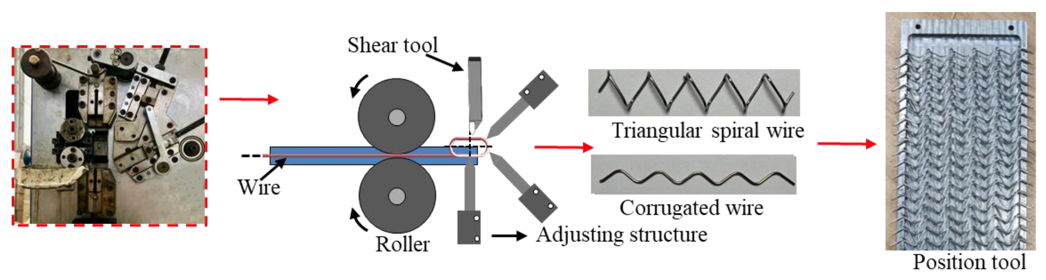
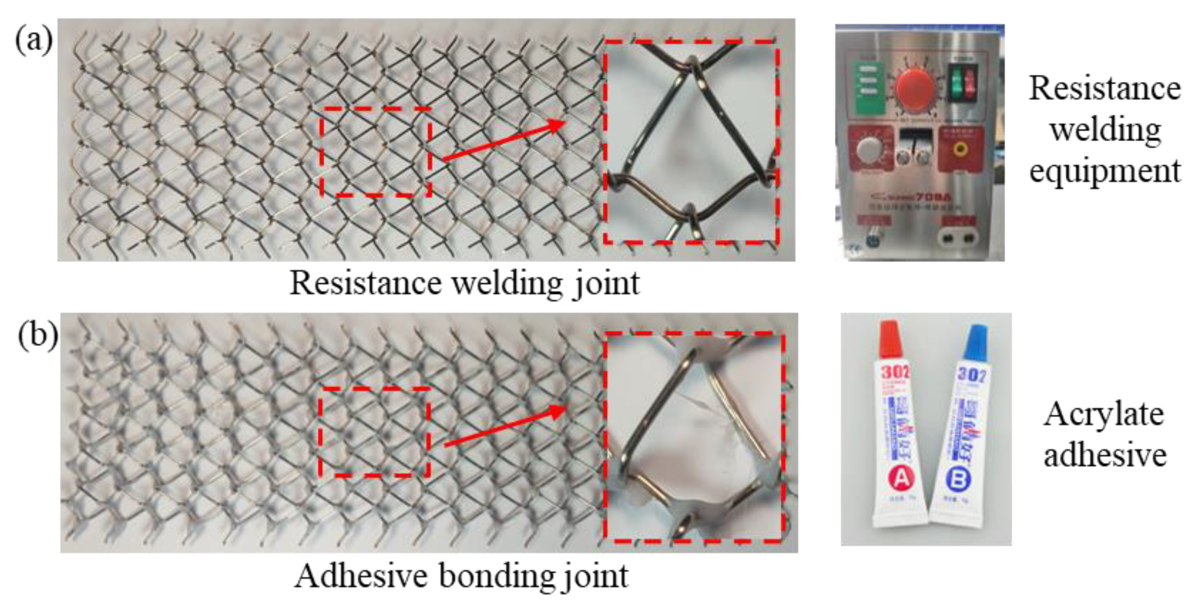
3.2.1. Fabrication of Asymmetric Crosslinked Metallic Wire Mesh

The fabrication of asymmetric crosslinked metallic wire mesh involves two primary processes. The first process entails weaving spiral wires according to the cell structures and the prescribed cell arrangements, which are usually dictated by the cell-dependent mechanical characteristics and engineering application requirements. Beginning with the weaving process in this work, the preparation of triangular spiral wire and corrugated wire should be performed under the following sequential steps, as shown in Figure 6. The first step involved straightening the received 304 stainless steel wire by turning it through a roller. The second step was to bend the wire into a pre-set shape using special tools. Finally, the bent wire was cut to the desired length using a shear tool. Once the basic metallic wires were prepared, suitable position tools (see Figure 6) were developed to fix the distributed wires, and a proper pre-load was applied to ensure that the interwoven joints were in full contact.
The other fabrication process involves joining the interwoven wires. In this work, there are two selected solutions, i.e., resistance spot welding and adhesive bonding. Figure 7a illustrates the resistance spot welding sample and its welding joint by using a SUNKKO 709A. The principle of resistance spot welding involves pressing the woven wire mesh sample between two electrodes, then applying an appropriate current at the contact surface of the sample, and finally stopping the current from welding the sample contact areas together. The main processing parameters for resistance spot welding include melting current (IM) and conduction time (TM). After several trial-and-error tests, an optimal process solution for resistance spot welding was achieved, with TM set at 200 ms and the IF set at 500 A. Another method to connect the interwoven joints is through glue adhesion, as shown in Figure 7b. After the mixing of the A glue and the B glue (graded 302 acrylic ester), a quantitative mixed glue can be applied to each joint using numerical control. Finally, a slight tensile preload should be performed for about one hour to ensure thorough drying of the glue and joint stability.

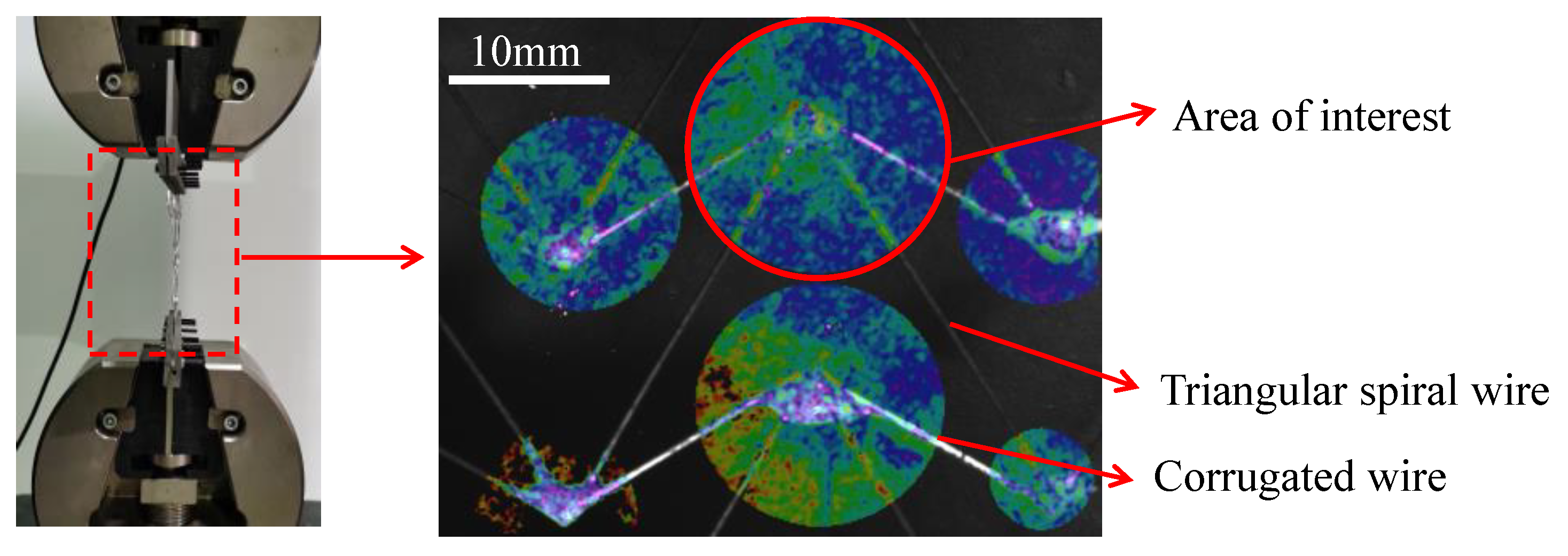
3.2.2. Uniaxial Tensile Test

Uniaxial tensile tests were performed using with a SHIMADZU testing machine with a maximum capacity of 50 kN. To determine the deformation field, a digital image correlation (DIC) system was employed, as depicted in Figure 8. To eliminate the region of inhomogeneous deformation gradient, an appropriate central area of interest (AOI) was selected, where the deformation was almost uniform. The tensile sample size was 170 mm × 100 mm, and the tests were conducted at room temperature with a nominal initial displacement rate of 5 mm/min. To ensure the reproducibility of the experimental results, three tests were conducted for each sample.

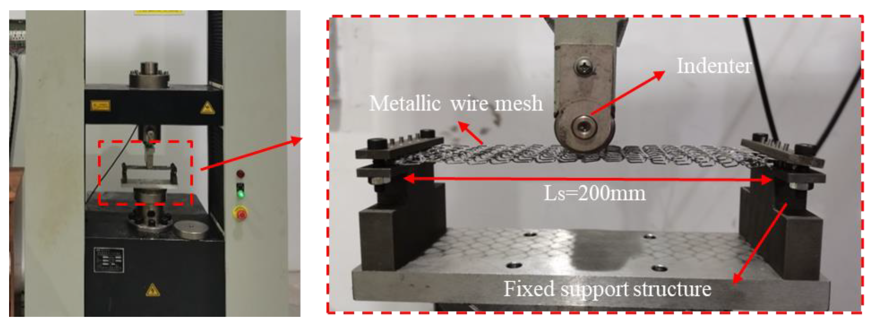
3.2.3. Three-Point Bending

Compared to the uniaxial tensile test, the three-point bending test is better suited for capturing elastic bending properties in three-dimensional problems, as it is associated with bending moment and deflection deformation. The effective deformation size of the bending specimen used in this study was 200 mm × 60 mm × 5.8 mm. The tools used for the three-point bending test are depicted in Figure 9, where load force is applied to the sample at the middle span by the displacement of the indenter at a deflection speed of 5.0 mm/min. The left and right sides of the sample are pressed by a fixed support structure.

3.3. Finite Element Analysis

3.3.1. Numerical Modeling

To capture the in-situ deformations of the wire mesh structure, a three-dimensional finite element analysis (FEA) was employed. First, the three-dimensional geometric models of the triangular spiral coil and corrugated wire were created using the commercial software SolidWorks. Then, these geometric models were imported into Hypermesh program for the meshing process. During the meshing process, the general C3D8R brick element in the simulation software Abaqus was adopted. The local mesh refinement in the small corner of wire was used to improve the convergence. The determination of mesh size in the FEM are associated with the mesh density, the mesh convergence, the outcome accuracy and the computing time. It is necessary to search for a balance between computing time and expected outcome accuracy. The trial-and-error method using several mesh sizes was employed to determine a suitable mesh configuration. As a result, the typical mesh size is about 0.2 mm × 0.2 mm × 0.4 mm. Each cross section of metallic wire can be divided into eight two dimensional elements, and then formed into three-dimensional elements by sweeping operation. The total number of the studied crosslinked metallic wire elements is up to 110,428. The basic wire material used in this study is the commonly used stainless steel grade 304, which exhibits excellent corrosion resistance, heat resistance, low-temperature strength, and outstanding mechanical properties. The basic material parameters of the as-received 304 stainless steel wire are listed in Table 1. The material constitutive model Swift law [30] was adopted to describe the isotropic hardening behavior.
During the numerical modeling of the three point bending of the asymmetric crosslinked metallic wire mesh, the contact between the deformation sample and the tool indenter is defined as a penalty friction formulation. The interface contact is set to a default frictional coefficient of 0.1, which belongs to the smooth boundary of wire contact. The deformation of the tri-angular spiral and corrugated wire interwoven joint was fixed by adhesive. Consequently, the interleaved joint was set as a tie constraint. This means that the elastic-plastic deformation of interwoven joints was ignored in the simulation. The indenter is hardly deformed compared to the asymmetric crosslinked metallic wire mesh structure; therefore, it can be set as an analytical rigid body. Finally, the default general contact was set in the interaction module of the numerical simulation to avoid metallic wire penetration.

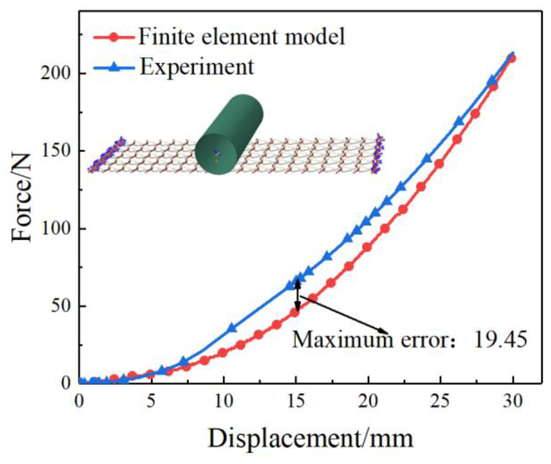
3.3.2. Preliminary Results of Numerical Simulation

The developed numerical model was validated experimentally using a selected case structure with cell parameters listed in Table 2. The case sample structure of asymmetric crosslinked metallic wire mesh consisted of five PPRC models in the longitudinal direction and eighteen PPRC models in the transverse direction. The two ends of the structure are completely fixed. The simulation was carried out by changing the displacement of the indenter, whose maximum deformation displacement was set to 30 mm in the gravity direction, with a diameter of 30 mm. Figure 10 presents a comparison of force-displacement loading curves between the numerical simulation and experimental results. The deviation between the predicted and measured curves is minor. Specifically, the maximum deviation of bending force is 19.45 N (less than 10% of maximum force) in the displacement of 30 mm. The mean error of static structure stiffness is 14%. Therefore, it can be acceptable for the effectivity of the developed numerical model.

4. Results and Discussion

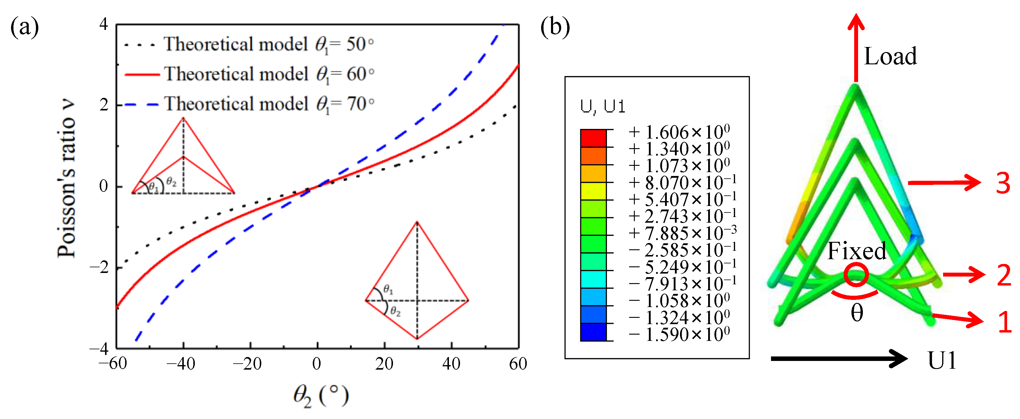
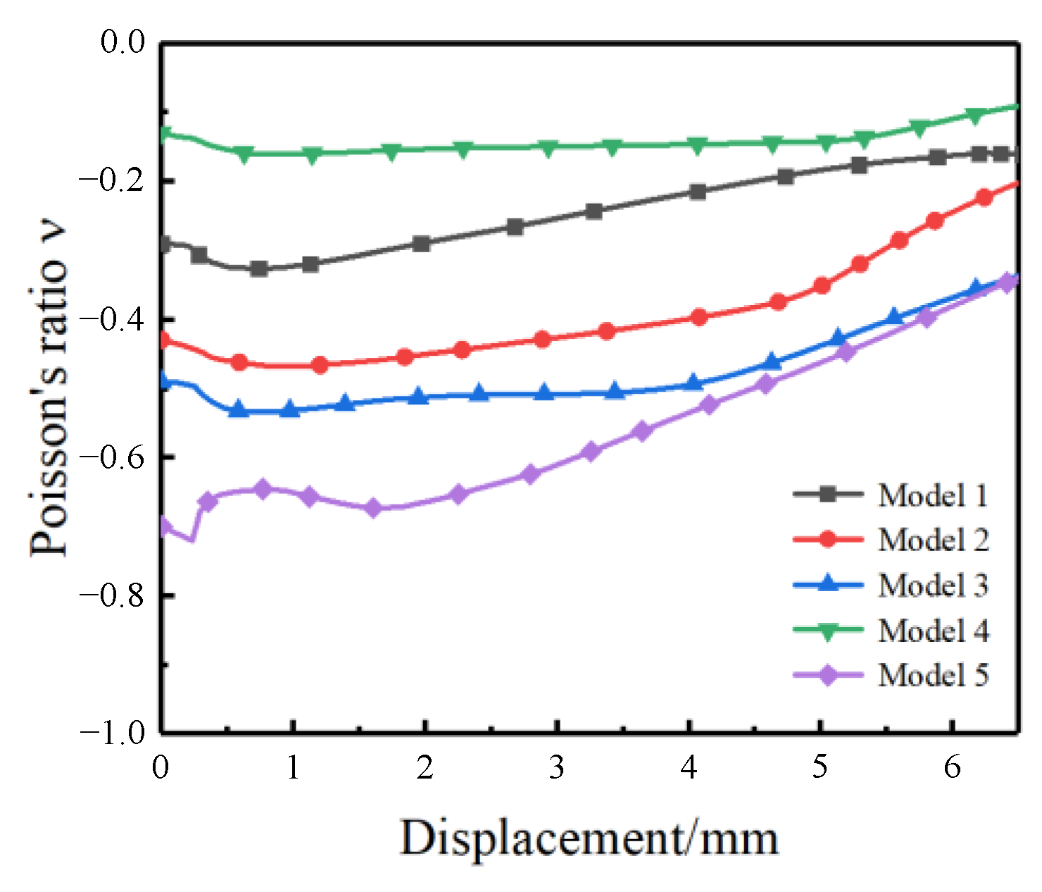
4.1. Influence of Cell Beam Angle on the Poisson’s Ratio

According to Equations (6) and (7), it can be found that the value of Poisson’s ratio is primarily determined by the beam angle of the cell. Regardless of the direction, the absolute magnitudes of NPRC and PPRC models can be considered identical. Figure 11a shows the theoretical evolution curves of Poisson’s ratio with θ2 when θ2 is a constant. It can be observed that when θ2 < 0, the cell is an NPRC model, and the value of v is negative. On the other hand, when θ2 > 0, the cell is a PPRC model, and the value of v is positive. As θ2 decreases, the negative Poisson’s ratio of the structure becomes more pronounced. Figure 11b shows a simulated deformation state of the NPRC model during the uniaxial tensile test. It can be observed that the NPRC model expands transversely from cell 1 to cell 2 under longitudinal stretch, and the negative Poisson’s ratio maintained until it reaches to cell 2. If the longitudinal stretch continues, the angle θ will change from a concave angle to a convex angle and cell 2 will turn into cell 3. It is noteworthy that the Poisson’s ratio of the entire structure changes from negative to positive during this transformation. Additionally, the corrugated wire undergoes a greater deformation, indicating that it bears the maximum force.
Table 3 lists the structural parameters of the selected five models for the verification of the theoretical model. The primary variable parameters are the cell beam angles θ1 and θ2. As demonstrated in Equations (6) and (7), the cell beam angle is the primary factor that affects Poisson’s ratio. Therefore, Poisson’s ratio is less correlated with l and b.
Figure 12 shows the evolution of Poisson’s ratio with displacement for models with different cell beam angles under uniaxial tensile loading. It is evident from the figure that the NPRC model displays strong auxetic characteristics during the initial stage of stretching. As the tensile displacement increases, the Poisson’s ratio value gradually increases as well. In addition, the angles θ1 and θ2 are positively correlated with the absolute Poisson’s ratio value. The numerical results presented above regarding the evolution of cell-dependent Poisson’s ratio are consistent with the theoretical analyses.

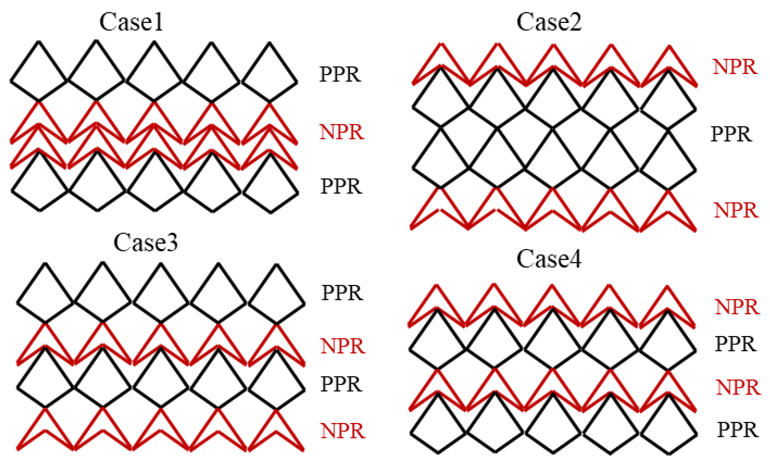
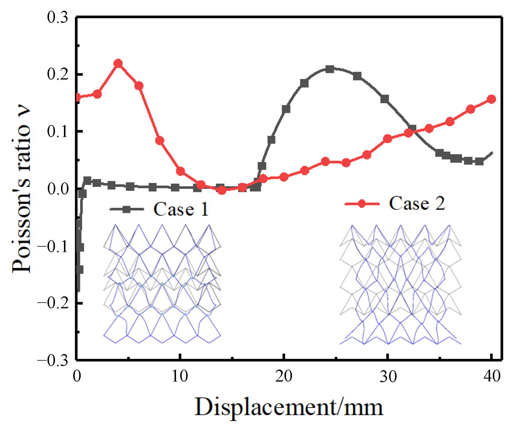
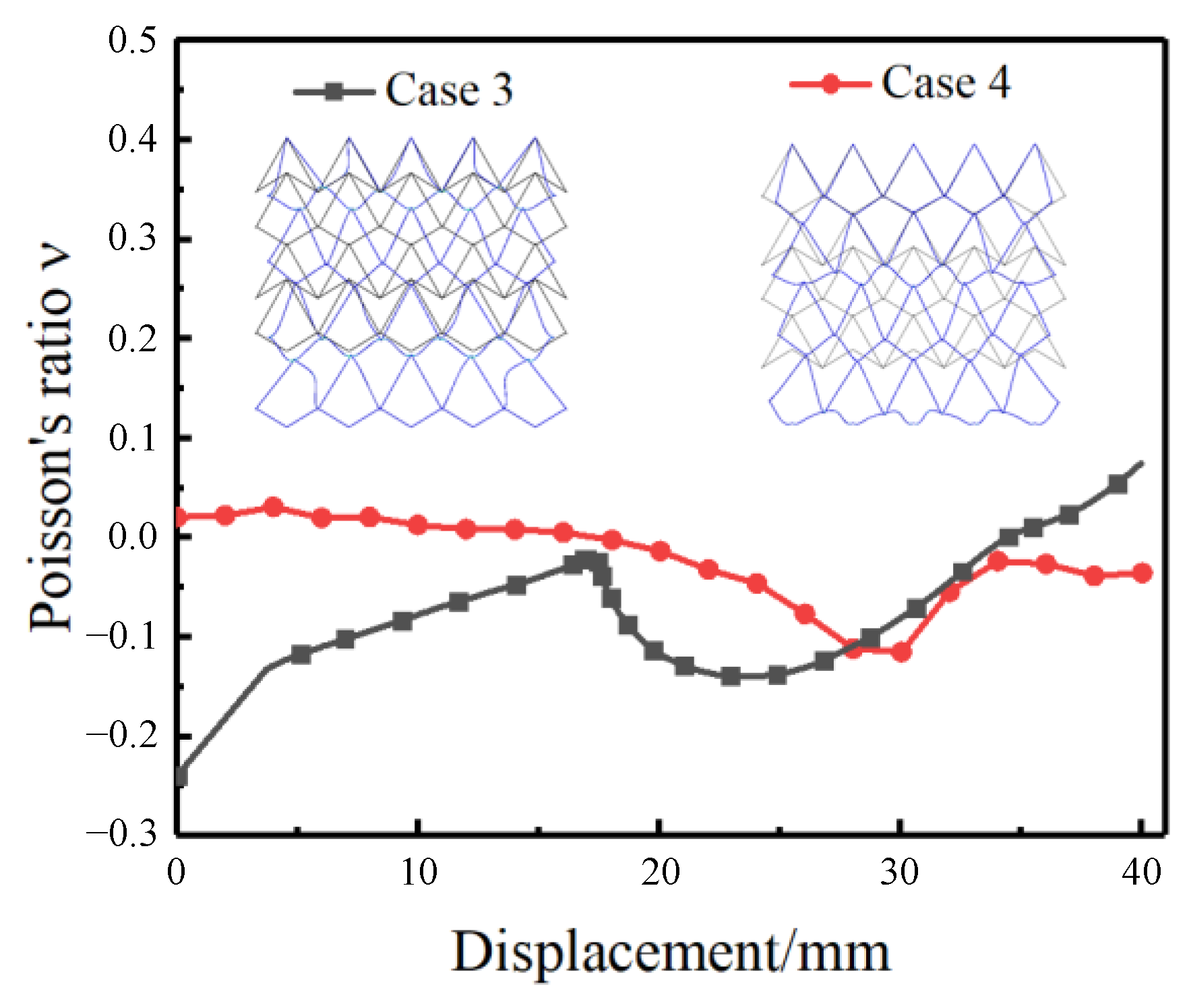
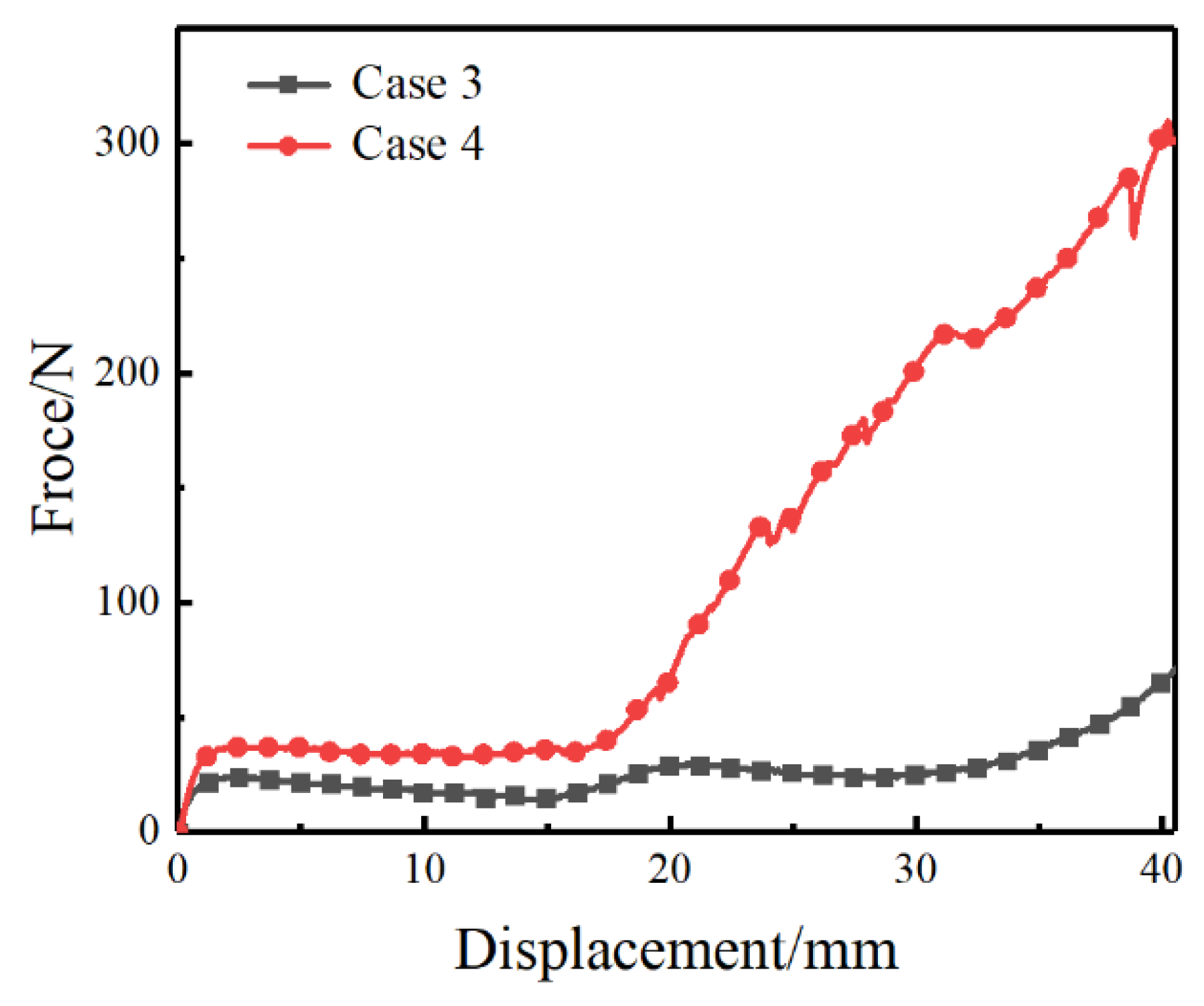
4.2. Effects of Hybrid Cell Pattern on Macroscopic Poisson’s Ratio

To investigate the impact of hybrid cell patterns on the macroscopic Poisson’s ratio of asymmetric crosslinked metallic wire mesh, the primary structural parameters of an angle cell geometry were applied, as listed in Table 4. This is attempted to avoid interference by internal cell geometrical elements. In this work, four cases with different cell patterns (see Figure 5) were adopted to analyze the effects of a hybrid cell pattern on macroscopic Poisson’s ratio by means of numerical and experimental methods.
Figure 13 illustrates the simulation results of the undeformed black wire mesh and the deformed blue wire mesh structure at the end of the loading path. It is evident from the figure that the macroscopic Poisson’s ratio value tends to be positive in the final stage of stretching. The blue schematic structure in the simulation results shows significant transverse shrinkage. In comparison to the model of Case 1, the middle area in the model of Case 2 mainly consists of the PPRC structure, leading to an apparent positive Poisson’s ratio phenomenon and significant transverse shrinkage. Notably, the macroscopic Poisson’s ratio of the Case 1 model approaches zero in the first half of the curves. The first layer area in the Case 1 model undergoes deformation under initial stretch, whereas the middle area experiences less deformation with a constant macroscopic Poisson’s ratio. This can be attributed to the layer-by-layer force transfer of the crosslinked metallic wire mesh model and the sensitivity of the NPRC structure to deformation under uniaxial stretching.
Due to the dispersed structure of the asymmetric crosslinked metallic wire mesh, the deformation distribution of the sample is transmitted layer by layer from the moving side of the grip to the fixed side. The PPRC structure, which is a valley-to-valley connection, exhibits higher stability compared to the NPRC structure. Figure 14 shows the force-displacement curves of Case 1 and Case 2 under uniaxial tensile loading. The results indicate that the deformable force of Case 2 is much larger than that of Case 1, which can be attributed to the PPRC structure carrying most of the load in Case 2. However, it should be noted that there are some fluctuations in the large displacement stage due to the failures of some interwoven joints.
Figure 15 shows the variation of macroscopic Poisson’s ratio for the models of Cases 3 and 4. Evidently, the Poisson’s ratio of Case 4 can be stabilized around zero Poisson’s ratio when the tensile displacement is within 20 mm. In Case 4, the first layer of the PPRC structure mainly absorbs the force with lateral shrinkage, while in the middle of the model area, the NPRC structure reduces the force transmission through large deformation. As a result, the lateral shrinkage phenomenon is reduced in the structural arrangement. Furthermore, it can be observed that the transverse shrinkage of Cases 3 and 4 is significantly smaller than that of the previous cases. Based on the above observations, it can be inferred that the alternate connection of PPRC and NPRC structures can effectively reduce the transverse shrinkage of the metallic wire mesh.
By observing the force-displacement curve in Figure 16, it can be seen that when the tensile displacement is greater than 20 mm, the bearing capacity of Case 4 increases sharply. In contrast, the force field of Case 3 is stable within a slight fluctuation. Case 3 is mainly due to the NPRC as the main load-bearing structure causing this phenomenon. It can be concluded that the cell pattern plays a considerable effect on the mechanical properties of asymmetric crosslinked metallic wire mesh.

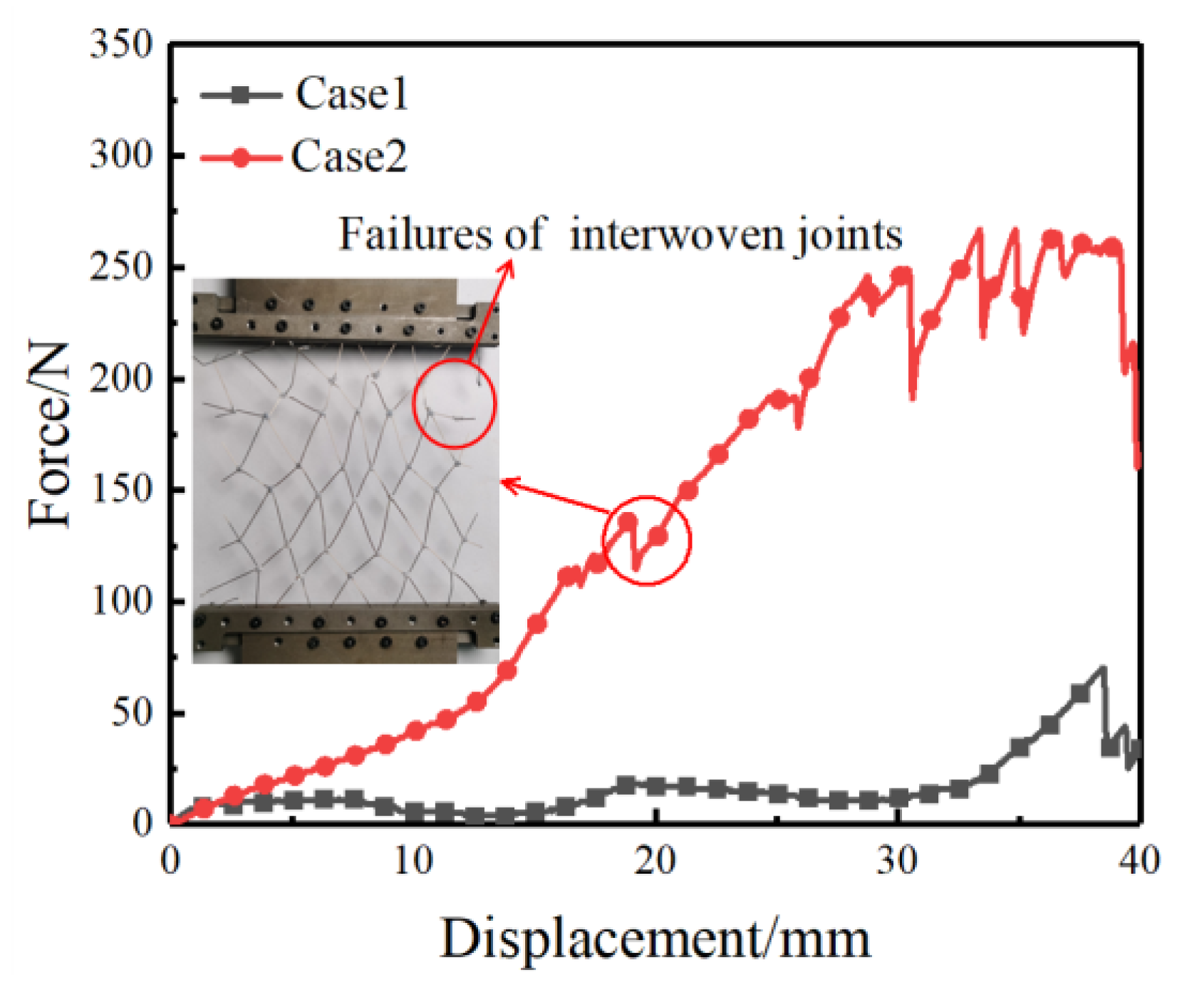
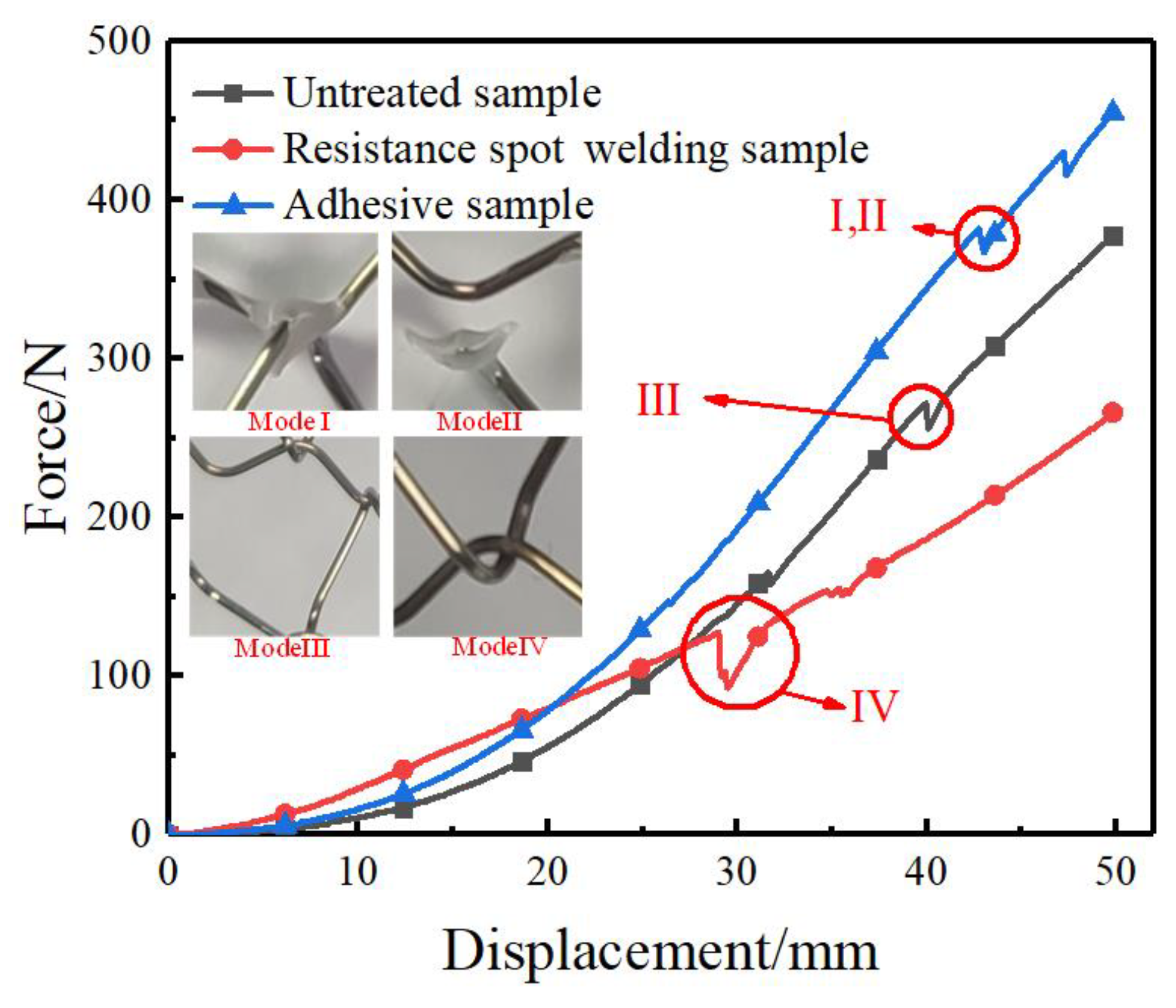
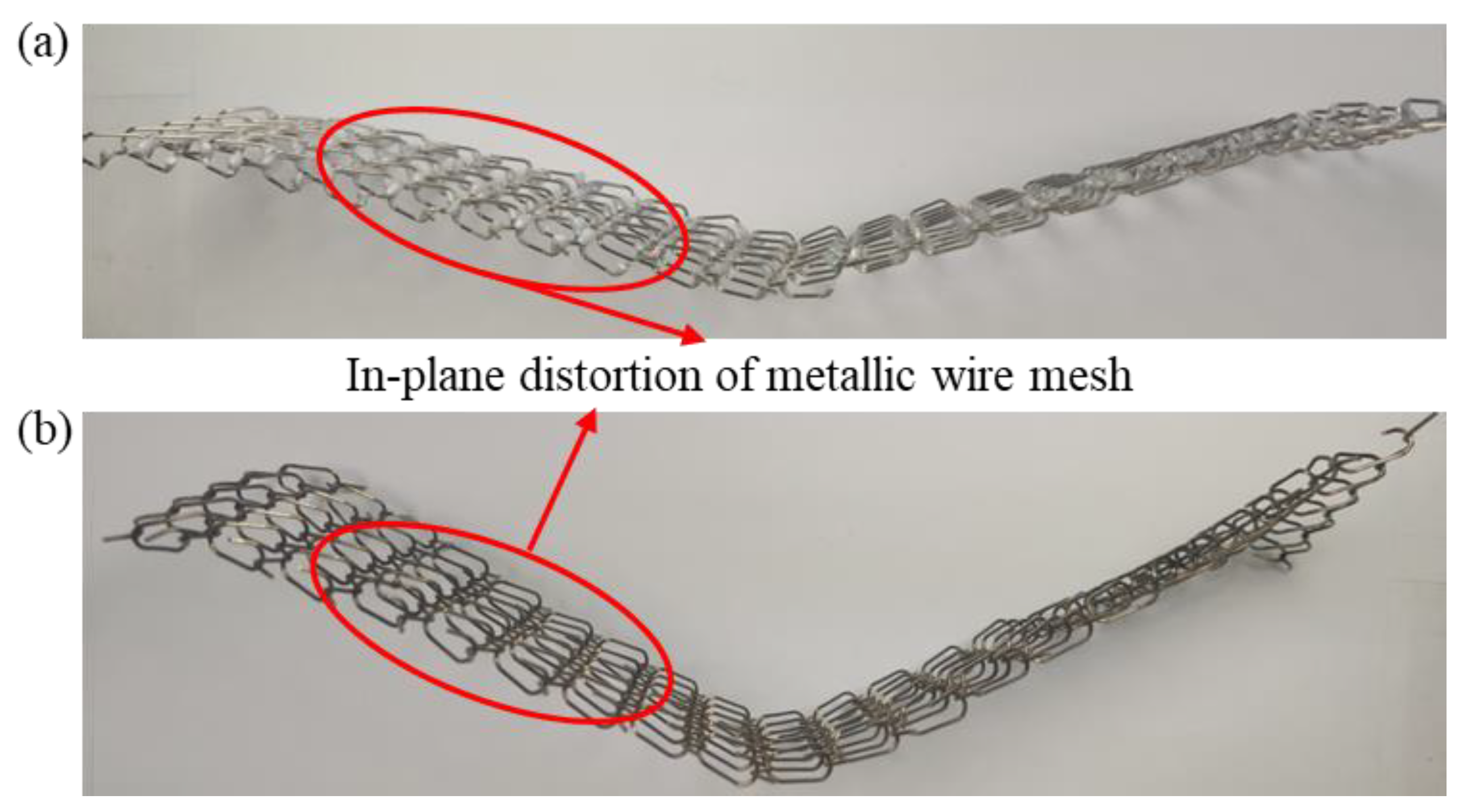
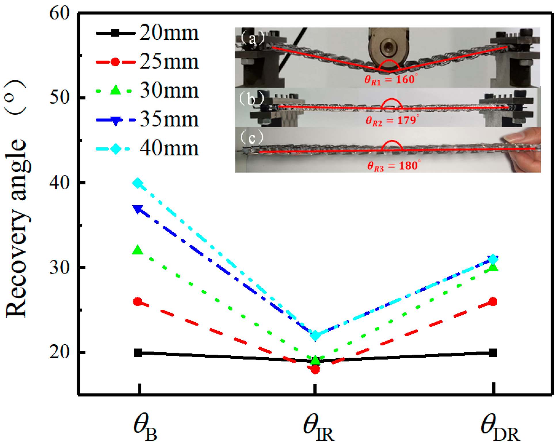
4.3. Influence of Interwoven Joint on Elastic Bending Property

To investigate the strength of interwoven joints and the buckling deformation of asymmetric crosslinked metallic wire mesh, three-point bending tests were conducted where the sample was clamped at both ends. Three different joint solutions, i.e., glue adhesion, resistance spot welding, and no interface connection, were tested. Figure 17 shows the typical force-displacement curves of asymmetric crosslinked metallic wire mesh with different joint solutions under three-point bending tests. Compared to the other two connection methods, the resistance spot welding sample exhibited a slower slope in its force–displacement curve. This could be due to the metallurgical process of resistance spot welding, which may have altered the mechanical properties of the braided joints. Furthermore, resistance spot welding with a better pressure resistance belongs to a rigid connection. The curves for glue adhesion and no interface connection exhibited similar trends, but the load-bearing performance of glue adhesion was superior. This is because the glued area absorbs a portion of the force before it is transferred to the woven joint.
The red circles in Figure 17 indicate the location of damage or failure modes for each sample during bending, with four main failure modes observed. Modes I and II are associated with the failure behavior of the adhesive joint, where uneven deformation leads to severe plastic deformation of some interwoven joints, resulting in the joint crack (Mode I) and joint section fracture (Mode II). For the untreated samples, the failure behavior, namely Mode III, is related to the unhook connection or no interfacial contact of crosslinked metallic wires. Mode IV is relevant to the failure behavior of resistance spot welded joint. It can be observed that it has the weakest mechanical resistance compared to the other joining technologies. Although it belongs to a metallurgical process with melting and heating solutions, there are no additional filter and few interfacial connections. This leads to the weak interwoven joint of resistance spot welding. If the proper filter of welding process or additive manufacturing can be adopted, the joint performance must be significantly enhanced. However, the corresponding advanced joining technologies are difficult for asymmetric crosslinked metallic wire mesh due to its intrinsic porous and complex structure. To address these issues, a joint solution combining resistance spot welding and glue adhesion was adopted with the former used for positioning the crosslinked metallic wires and the latter ensuring a suitable joint strength.
In this work, the effect of the interwoven joint on the elastic bending property is performed, particularly in elastic bending recovery. Two interesting bending-induced deformation phenomena were observed after unloading. One is the significant asymmetric in-plane distortion for the samples made by glue adhesion and resistance spot welding, as shown in Figure 18. The in-plane distortion may be caused by the unidirectional helical structure of the triangular spiral wire and by the asymmetric cell pattern of the asymmetric crosslinked metallic wire mesh structure. It may also be due to the plastic hinge of interwoven joint which can cause unevenly deformed paths of the whole sample. Therefore, controlling the fabrication process to obtain uniform or consistent samples is critical for a performance analysis.
The second interesting phenomenon is the large elastic bending recovery. The bending recovery angle variations of the asymmetric crosslinked metallic wire mesh at various time points with different deflections are displayed in Figure 19. Within one day, the bentness of asymmetric crosslinked metallic wire mesh structure can be completely recovered when the bending deflection amplitude is less than 25 mm. The sources of elastic bending recovery are the release of residual torsion stress field in interwoven joints and bent wires. As for the time-dependent phenomenon, it is related to the creep behaviors of adhesive materials. The in-plane distortion and elastic bending recovery under bending deformation will be further investigated in future work.

5. Conclusions

In this work, a novel asymmetric crosslinked metallic wire mesh was proposed. It has great potentials for practical applications such as rockfall protection, flexible aircraft skin with metallic skeleton and the reinforcement of steel cages. The fabrication process of asymmetric crosslinked metallic wire mesh is introduced in detail. By means of theoretical, numerical and experimental characterization methods, the mechanical properties (e.g., Poisson’s ratio and bending recovery phenomenon) of structure under different strain paths are investigated. The main research contents of this work can be drawn as follows:
(1) The Poisson’s ratio of the asymmetric crosslinked metallic wire mesh is determined based on the Euler beam theory, with the angle of the cell beams being the dominant factor rather than other geometric parameters. Analytical and numerical predictions of Poisson’s ratio are in good agreement and have sufficient accuracy for engineering application.
(2) The use of a hybrid cell pattern in the asymmetric crosslinked metallic wire mesh can effectively reduce transverse shrinkage and achieve arbitrary macroscopic Poisson’s ratio, including for zero Poisson’s ratio within a certain stretching range.
(3) Through the analysis of structure failure modes, the interwoven joining technology which combined resistance spot welding and glue adhesion can be a proper solution in the manufacturing process of asymmetric crosslinked metallic wire mesh.
(4) The in-plane distortion and elastic bending recovery of the asymmetric crosslinked metallic wire mesh structure are analyzed, along with their underlying causes. The interwoven joint characteristics play a dominant role in elastic-plastic deformation behaviors.

Author Contributions

F.W.; Conceptualization, formal analysis, original writing. Z.L.; methodology. C.L. formal analysis; S.G.; editing and reviewing. X.X.; investigation, supervision, revise and editing. All authors have read and agreed to the published version of the manuscript.

Funding

This work received highly appreciated financial support from the National Natural Science Foundation of China (No. 12272094), the Key Project of National Defence Innovation Zone of Science and Technology Commission of CMC (XXX-033-01) and the Natural Science Foundation of Fujian Province of China (No. 2022J01541).

Data Availability Statement

The data used to support the findings of this study are included within the article.

Acknowledgments

The authors would like to express many thanks to Senior Engineer Yunhua Deng of AVIC Manufacturing Technology Institute, China for his valuable comments and motivating discussions.

Conflicts of Interest

The author(s) declare no potential conflict of interest with respect to the research, authorship, and/or publication of this article.

Appendix A

Because of structure symmetry, only half of the PPRC structure (i.e., structure A-B-C) is considered, and the horizontal displacement and rotation of A and C are constrained with the reaction force and moment being NA, MA, NC and MC. Additionally, vertex B is entirely fixed. The vertices A and C have identical deformation in horizontal displacement but can move freely along vertical displacement. A uniform remote stress (σ) is assumed to impose the PPRC, which corresponds to vertical force 2PA = 2PC = 2lbσ applied at points A and C in Figure 2. Therefore, considering the special geometric features and the deformation compatibility conditions, the following equilibrium equations can be obtained:
δ P A N A P A + δ M A N A M A + δ N A N A N A = δ P C N C P C + δ M C N C M C + δ N C N C N C
δ P A M A P A + δ M A M A M A + δ N A M A N A = 0
δ P C M C P C + δ M C M C M C + δ N C M C N C = 0
where δij represents the j-th displacement component due to the force in i direction, as given by:
δ P A N A = l 1 3 sin θ 1 cos θ 1 3 E I
δ P C N C = l 2 3 sin θ 2 cos θ 2 3 E I
δ M A N A = δ N A M A = l 1 2 sin θ 1 2 E I
δ N A N A = l 1 3 sin 2 θ 1 3 E I
δ N C N C = l 2 3 sin 2 θ 2 3 E I
δ P A M A = δ M A P A = l 1 2 cos θ 1 2 E I
δ P C M C = δ M C P C = l 2 2 cos θ 2 2 E I
δ M A M A = l 1 E I
δ M C M C = l 2 E I
l = l 1 cos θ 1 = l 2 cos θ 2
where I is the second moment of inertia and E is the elastic modulus of the wire material. Accordingly, the expressions of NA, MA, NC and MC can be obtained from Equations (A1)–(A14) as follows:
N A = P A ( tan θ 1 cos θ 2 tan θ 2 cos θ 1 ) tan 2 θ 1 cos θ 2 + tan 2 θ 2 cos θ 1
N C = P C ( tan θ 1 cos θ 2 tan θ 2 cos θ 1 ) tan 2 θ 1 cos θ 2 + tan 2 θ 2 cos θ 1
M A = P A l tan θ 2 cos θ 1 ( tan θ 1 + tan θ 2 ) 2 ( tan 2 θ 1 cos θ 2 + tan 2 θ 2 cos θ 1 )
M C = P C l tan θ 1 cos θ 2 ( tan θ 1 + tan θ 2 ) 2 ( tan 2 θ 1 cos θ 2 + tan 2 θ 2 cos θ 1 )
The displacement of points A and C in the y direction can be expressed as follows:
u y A = δ P A P A P A + δ M A P A M A + δ P A N A N A
u y C = δ P C P C P C + δ M C P C M C + δ P C N C N C
where
δ P A P A = l 1 3 cos 2 θ 1 3 E I
δ P C P C = l 2 3 cos 2 θ 2 3 E I
Similarly, the displacement of point A and C in the direction of x can be expressed as:
u x A = u x C = δ P A N A P A + δ M A N A M A + δ N A N A N A
Combined with Equations (A19), (A20) and (A23), the strain field in the x and y direction can be derived.
ε y = u y A + u y B l ( tan θ 1 + tan θ 2 )
ε x = u x A l
The effective Poisson’s ratio vxy is defined as the ratio of strains in the transverse and longitudinal directions.
v x y = ε x ε y = tan θ 1 tan θ 2
Similarly, when the NPRC structure is compressed in the y direction as shown in Figure 3, which corresponds to the vertical force applied at points A and C, 2P′A = 2P′C = 2lbσ, the following equation of equilibrium is obtained:
δ P A N A P A + δ M A N A M A + δ N A N A N A = δ P C N C P C + δ M C N C M C + δ N C N C N C
δ P A M A P A + δ M A M A M A + δ N A M A N A = 0
δ P C M C P C + δ M C M C M C + δ N C M C N C = 0
Then, N A , N C , M A and M A can be obtained from Equations (A27)–(A29). The displacements of points A and C in x and y directions can be expressed as:
u y A = δ P A P A P A + δ M A P A M A + δ P A N A N A
u y C = δ P C P C P C + δ M C P C M C + δ P C N C N C
u x A = u x C = δ P A N A P A + δ M A N A M A + δ N A N A N A
According to the equation mentioned above, the normal strains in x and y directions can be derived as:
ε y = u y A + u y B l ( tan θ 1 tan θ 2 )
ε x = u y A l
The equivalent Poisson’s ratio of NPRC structures in the y can be expressed as:
v x y = ε x ε y = cot θ 1 cot θ 2

References

  1. Yang, G.; Xu, R.; Wang, Y.; Zhu, Y.; Ren, F.; Li, C.; Wu, J. Pore-scale numerical simulations of flow and convective heat transfer in a porous woven metal mesh. Chem. Eng. Sci. 2022, 256, 117696. [Google Scholar] [CrossRef]
  2. Joo, J.-H.; Kang, K.-J.; Kim, T.; Lu, T. Forced convective heat transfer in all metallic wire-woven bulk Kagome sandwich panels. Int. J. Heat Mass Transf. 2011, 54, 5658–5662. [Google Scholar] [CrossRef]
  3. Iwaniszyn, M.; Sindera, K.; Gancarczyk, A.; Korpys, M.; Jedrzejczyk, R.J.; Kolodziej, A.; Jodłowski, P.J. Experimental and CFD investigation of heat transfer and flow resistance in woven wire gauzes. Chem. Eng. Process. 2021, 163, 108364. [Google Scholar] [CrossRef]
  4. Wang, G.S.; Sun, Y.H.; Zhang, A.; Zheng, L.; Lv, Y.Z.; Wu, H.J.; Yang, Y. Study on the Impact Resistance of Metal Flexible Net to Rock fall. Shock Vib. 2020, 2020, 9612405. [Google Scholar] [CrossRef]
  5. Trad, A.; Limam, A. Load testing and simulation of asymmetric cable-net used for flexible rockfall protection barriers. Eur. J. Environ. Civ. Eng. 2021, 25, 7685–7702. [Google Scholar] [CrossRef]
  6. Escallon, J.P.; Boetticher, V.; Wendeler, C.; Chatzi, E.; Bartelt, P. Mechanics of chain-link wire nets with loose connections. Eng. Struct. 2015, 101, 68–87. [Google Scholar] [CrossRef]
  7. Santos, L.; Izzuddin, B.A.; Macorini, L. Gradient-based optimisation of rectangular honeycomb core sandwich panels. Struct. Multidiscip. Optim. 2022, 65, 242. [Google Scholar] [CrossRef]
  8. Shuang, L.; Yang, J.S.; Rudiger, S.; Wu, L.Z.; Schroder, K.U. Compression and hysteresis responses of multilayer gradient composite lattice sandwich panels. Mar. Struct. 2021, 75, 102845. [Google Scholar] [CrossRef]
  9. Borges, H.; Martínez, G.; Graciano, C. Impact response of expanded metal tubes: A numerical investigation. Thin-Walled Struct. 2016, 105, 71–80. [Google Scholar] [CrossRef]
  10. Nedoushan, R.J. Improvement of energy absorption of expanded metal tubular structures under compressive loads. Thin-Walled Struct. 2020, 157, 107058. [Google Scholar] [CrossRef]
  11. Zhang, C.P.; Khan, A.; Cai, J.X.; Liang, C.W.; Liu, Y.J.; Deng, J.H.; Huang, S.; Li, G.; Li, W.-D. Stretchable Transparent Electrodes with Solution-Processed Regular Metal Mesh for an Electroluminescent Light-Emitting Film. ACS Appl. Mater. Interfaces 2018, 10, 21009–21017. [Google Scholar] [CrossRef]
  12. Stolbchenko, M.; Makeieva, H.; Grydin, O.; Ya, F.; Schaper, M. Strain parameters at hot rolling of aluminum strips reinforced with steel netting. J. Sandw. Struct. Mater. 2020, 22, 2009–2029. [Google Scholar] [CrossRef]
  13. Yang, T.; Yang, P.; Zou, Z.Y.; Ma, P. Mechanical properties of warp-knitted metal mesh fabric under biaxial tension loading. Text. Res. J. 2021, 91, 1368–1379. [Google Scholar] [CrossRef]
  14. Kang, K.-J. Wire-woven cellular metals: The present and future. Prog. Mater. Sci. 2015, 69, 213–307. [Google Scholar] [CrossRef]
  15. Lee, K.W.; Park, J.-S.; Jeon, I.; Kang, K.-J. Equivalent material properties of a wire-woven cellular core. Mech. Mater. 2013, 57, 1–14. [Google Scholar] [CrossRef]
  16. Xue, X.; Wu, F.; Zheng, C.; Wei, Y.; Chen, X.; Bai, H. Research progress of flexible sandwich structure materials with metal-rubber damping core. Mater. Rep. 2022, 36, 22040029-11. [Google Scholar]
  17. Albrecht, V.B.; Axel, V. Numerical modeling of chain-link steel wire nets with discrete elements. Can. Geotech. J. 2019, 56, 398–419. [Google Scholar]
  18. Zhang, Q.; Jiang, W.C.; Zhang, Y.T.; Luo, Y.; Tu, S.-T. Effective elastic constants of wire mesh material studied by theoretical and finite element methods. Compos. Struct. 2017, 184, 474–483. [Google Scholar] [CrossRef]
  19. Li, T.J.; Jiang, J.; Shen, T.T.; Wang, Z.W. Analysis of mechanical properties of wire mesh for mesh reflectors by fractal mechanics. Int. J. Mech. Sci. 2015, 92, 90–97. [Google Scholar] [CrossRef]
  20. Yang, H.; Ma, L. Impact resistance of additively manufactured 3D double-U auxetic structures. Thin-Walled Struct. 2021, 169, 108373. [Google Scholar] [CrossRef]
  21. Xue, X.; Shen, G.J.; Wu, X.Q.; Xiong, Y.L.Z.; Liao, J.; Bai, H.B. Thermo-mechanical performances of elastic–porous materials with metallic wire mesh structures. Compos. Struct. 2022, 297, 115918. [Google Scholar] [CrossRef]
  22. Wu, F.; Xiao, X.; Yang, J.; Gao, X.D. Quasi-static axial crushing behaviour and energy absorption of novel metal rope crochet-sintered mesh tubes. Thin-Walled Struct. 2018, 127, 120–134. [Google Scholar] [CrossRef]
  23. Dong, J.H.; Wang, Y.J.; Jin, F.N.; Fan, H.L. Crushing behaviours of buckling-induced metallic meta-lattice structures. Def. Technol. 2022, 18, 1301–13010. [Google Scholar] [CrossRef]
  24. Formisano, A.; Durante, M.; Viscusi, A.; Garrino, L.G. Mechanical behaviour and collapse mechanisms of innovative aluminum foam-based sandwich panels under three-point bending. Int. J. Adv. Manuf. Technol. 2021, 112, 1301–1310. [Google Scholar] [CrossRef]
  25. Xue, X.; Lin, C.C.; Wu, F.; Li, Z.; Liao, J. Lattice structures with negative Poisson’s ratio: A review. Mater. Today Commun. 2023, 34, 105132. [Google Scholar] [CrossRef]
  26. Magalhaes, R.; Subramani, P.; Lisner, T.; Rana, S.; Ghiassi, B.; Fangueiro, R.; Oliveira, D.V.; Lourenco, P.B. Development, characterization and analysis of auxetic structures from braided composites and study the influence of material and structural parameters. Compos. Part A Appl. Sci. Manuf. 2016, 87, 86–87. [Google Scholar] [CrossRef]
  27. Paglioccaa, N.; Uddin, K.Z.; Anni, I.A.; Shen, C.; Youssef, G.; Koohbor, B. Flexible planar metamaterials with tunable Poisson’s ratios. Mater. Des. 2022, 215, 110446. [Google Scholar] [CrossRef]
  28. Yao, J.F.; Su, Y.F.; Scarpa, F.; Li, Y. An optimization approach to design deformation patterns in perforated mechanical metamaterials using distributions of Poisson’s ratio-based unit cells. Compos. Struct. 2022, 281, 115015. [Google Scholar] [CrossRef]
  29. Wang, M.Z.; Wu, H.Z.; Yang, L.; Chen, A.; Chen, P.; Wang, H.; Chen, Z.; Yan, C. Structure design of arc-shaped auxetic metamaterials with tunable Poisson’s ratio. Mech. Adv. Mater. Struct. 2022, 30, 1426–1436. [Google Scholar] [CrossRef]
  30. Desu, R.K.; Krishnamurthy, H.N.; Balu, A.; Gupta, A.K.; Singh, S.K. Mechanical properties of Austenitic Stainless Steel 304L and 316L at elevated temperatures. J. Mater. Res. Technol. 2016, 5, 13–20. [Google Scholar] [CrossRef]
Figure 1. Simplified unit cell structures of RVE and the corresponding geometrical parameters: (a) PPRC and (b) NPRC; (c) cell thickness b.
Symmetry 15 00941 g001
Figure 2. Loading-bearing diagram of PPRC.
Symmetry 15 00941 g002
Figure 3. Loading-bearing diagram of NPRC.
Symmetry 15 00941 g003
Figure 4. Illustration of asymmetric crosslinked metallic wire mesh with different cell structures.
Symmetry 15 00941 g004
Figure 5. Four different types of asymmetric crosslinked metallic wire mesh structures associated with hybrid patterns based on arbitrary Poisson’s ratio.
Symmetry 15 00941 g005
Figure 6. Weaving process of asymmetric crosslinked metallic wire mesh.
Symmetry 15 00941 g006
Figure 7. Interwoven joining technologies of asymmetric crosslinked metallic wire mesh: (a) resistance spot welding and (b) adhesive bonding.
Symmetry 15 00941 g007
Figure 8. Uniaxial tensile test platform and samples.
Symmetry 15 00941 g008
Figure 9. Experimental setup of three-point bending test.
Symmetry 15 00941 g009
Figure 10. Comparison of load–displacement curves obtained from the finite element analysis and the three-point bending experiment.
Symmetry 15 00941 g010
Figure 11. (a) Theoretical evolution curve of Poisson’s ratio with θ2 and (b) deformation process of single cell based on FEA.
Symmetry 15 00941 g011
Figure 12. Simulation results of macroscopic Poisson’s ratio variation curves with displacement by using different models.
Symmetry 15 00941 g012
Figure 13. Macroscopic Poisson’s ratio variation curves with displacement for Cases 1 and 2.
Symmetry 15 00941 g013
Figure 14. Force-displacement curves of Case1 and 2 under uniaxial tensile test.
Symmetry 15 00941 g014
Figure 15. Macroscopic Poisson’s ratio variation curves with displacement for Cases 3 and 4.
Symmetry 15 00941 g015
Figure 16. Force-displacement curves of uniaxial tensile test for Cases 3 and 4.
Symmetry 15 00941 g016
Figure 17. Force–displacement curves of metallic wire mesh with different joint solutions.
Symmetry 15 00941 g017
Figure 18. In-plane distortion of asymmetric crosslinked metallic wire mesh with different connection methods after the bending experiment: (a) glue adhesion (b) resistance spot welding.
Symmetry 15 00941 g018
Figure 19. Elastic bending recovery angles of metallic wire mesh with different deflection: (a) bending angle θB (θB = 180° − θR1); (b) instantaneous recovery angle θIR (θIR = 180° − θR2); (c) one-day recovery angle θDR (θDR = 180° − θ3).
Symmetry 15 00941 g019
Table 1. Material parameters of the used 304 stainless steel wire.
Elastic Modulus (MPa)Density (g/mm3)Poisson’s RatioStrain Hardening Exponent (n) Strength Coefficient (K)
1.9 × 1057.8 × 10−30.30.451400
Table 2. Geometric parameters the cell used to validate the numerical model.
Geometric
Parameters
l/mmb/mmθ1θ2
Value65.860°30°
Table 3. Structural parameters of selected models for the verification of the theoretical model.
Sample Numberl/mmb/mm|θ1||θ2|
Model 165.860°20°
Model 265.860°30°
Model 365.860°40°
Model 465.850°30°
Model 565.870°30°
Table 4. Main parameters of cell structure for Case 1–4.
l/mmb/mm|θ1||θ2|
121.560°30°
Disclaimer/Publisher’s Note: The statements, opinions and data contained in all publications are solely those of the individual author(s) and contributor(s) and not of MDPI and/or the editor(s). MDPI and/or the editor(s) disclaim responsibility for any injury to people or property resulting from any ideas, methods, instructions or products referred to in the content.

