1. Introduction
In recent years, manufacturing organizations have been driven to develop processes motivated by “smart manufacturing” or Industry 4.0. The term Industry 4.0 emerged during the second decade of this century in Germany as a very broad concept. However, it can be summarized as the digital transformation of industry which controls its processes in a comprehensive way, making use of new technologies.
This brings a series of challenges that can be understood either as managerial or technological, according to Rikalovic et al. and Bajic et al. [
1,
2]. In this sense, the work of Bakhtari et al. [
3] shows an interpretative structural modeling approach that identifies 12 different challenges associated with Industry 4.0 implementation, where challenges 2 and 3 refer to the lack of education and skill training programs and the lack of a skilled workforce, respectively. Their results suggest that challenge 2 has high driving power and low dependence power, meaning that it acts as one of the two main challenges of the total twelve and can thus be considered a key challenge. Meanwhile, challenge 3 has high driving power together with high dependence power, which means it is a linking and unstable challenge that will affect others.
Therefore, the arrival of Industry 4.0 has resulted in changes and requirements for new and improved professional skills that can adapt to new technologies [
4].
As Ninan et al. [
5] hold, in this era of the Industrial Revolution 4.0, employees should not only focus on acquiring the skillset needed to do a job, but with digitalization and automation, employees will have to equip themselves with the right skills to survive. In 2017, Blanco et al. [
6] analyzed how Industry 4.0 affects workplaces and the need for staff training. In addition, they comment on professions at risk of automation based on the work of Morron [
7] and Frey and Osborne [
8].
Blanco et al. [
6] also point out that companies will increasingly demand vocational training specialists to cover needs, among others, in 3D industrial design and, at the university graduate level, within the science, technology, engineering, and mathematics (STEM) fields linked to Industry 4.0, assuming that the technologies linked to 3D simulation will undergo important developments.
Then again, while Industry 4.0 has not yet been consolidated, the next step, Industry 5.0, is already being considered, which aims to transform the industrial sector through the use of artificial intelligence (AI), linking machines and humans [
6].
If Industry 4.0 aims to automate processes and decrease human involvement in production lines, this new and upcoming industrial revolution, Industry 5.0, aims to merge human ingenuity with cognitive computing [
9].
According to some authors, such as Østergaard [
10] or Demir et al. [
11], a collaboration between humans and machines must exist where the creative aspect of human beings should be the determinant.
The work of Carro and Sarmiento [
12] aims at establishing the functions and skills required by the human factor as an integral part of the transition from Industry 4.0 to Industry 5.0. Among the results found, they highlight the functions and skills that, in this digital era, will be required by humans and must be considered fundamental pillars within the process of innovation and sustainable development by the industrial sector. Under these terms, authors wonder “What are the functions and skills required by the human factor as part of its new role in the transition from Industry 4.0 to Industry 5.0?”
From the analysis of the transition process, they identified functions that require the strengthening and development of human skills. This includes the modeling of physical systems or products in virtual form that allow modifications to be made without the need to make a priori physical prototypes. This requires human capital with the knowledge of computer-aided design (CAD), computer-aided manufacturing (CAM), and computer-aided engineering (CAE).
Given the present and future needs of human capital linked to the world of design and simulation, it must be understood that the design of any product always starts from the imagination of its creator: an idea that generally adopts a three-dimensional form that needs to be transferred to paper or to a computer screen, that is, to a two-dimensional space, either to obtain a realistic perspective of the object or to obtain what is generally known as a manufacturing drawing. But for this to happen, it is necessary for an individual to have the capability and knowledge of how to capture these ideas on a 2D surface that best suits a given case.
Within the university and training context, not only the knowledge acquired in other subjects but also the knowledge and learning obtained in specific fields such as engineering or graphic architecture come into play. In these areas, lectures on metric geometry and descriptive geometry are traditionally taught in first-year courses, while later, in higher and more advanced courses, technical drawing is applied to real cases. All this learning is ultimately demanded by and rewarded during the development of industrial or architectural projects. Nevertheless, all this acquired knowledge cannot lead to satisfactory end results if the engineer or architect does not possess what are known as “spatial skills”.
The controversy of whether performance in intelligence depended on a single general aspect or, to the contrary, on various specific factors [
13] began with the work of Alfred Binet (1817–1911). Later, researchers such as the mechanical engineer and psychologist Louis Leon Thurstone (1887–1955) and his wife Dr. Thelma Gwinn Thurstone (1897–1993) made great advances in the study of mental abilities through their theory and subsequent studies on primary mental abilities. They concluded that intelligence is made up of various factors or primary abilities independent of each other that would explain intellectual functioning with greater accuracy than a general factor. Thus, according to Thurstone, of the seven primary mental aptitudes linked to cognitive capacities, that make up intelligence, five of them can be measured by means of the Primary Mental Aptitudes Test: verbal comprehension, verbal fluency, numerical comprehension, spatial comprehension, and general reasoning or induction. Among these is found what is known today as visualization, conception, or spatial comprehension which, in the scientific literature, is generally referred to as “spatial ability”. Spatial comprehension or conception refers to the ability to imagine and conceive objects in two or three dimensions based on the visualization of figures or shapes from different positions in space, on rotation tasks, or on spatial orientation.
In 1947, Guilford and Lacey [
14] proposed two sub-factors: “spatial visualization” and “spatial orientation”. Later, based on the work of Mcgee [
15], the authors Sorby [
16] and Tartre [
17] subdivided spatial skills into two distinct aspects: spatial visualization and spatial orientation. Also, spatial visualization can be composed of other concepts such as mental rotation and mental transformation. Meanwhile, other authors such as Maier [
18] proposed a classification according to five factors (spatial perception, spatial visualization, mental rotations, spatial rotations, and spatial orientation). Although the body of research on this subject is large, some of the concepts given by different researchers overlap or are confused with each other. At present, Tartre’s theory and concepts are the most commonly accepted.
Vázquez and Noriega [
19] point out that there is no unanimous agreement on the definition of spatial competence despite there have been different studies that focus on the need to define this concept. By mentioning the work of authors such as Linn and Petersen [
20], they say that spatial competence is the ability to represent, generate, remember, and transform non-linguistic information. This ability can be grouped into three categories: (1) spatial perception, which refers to the ability to situate oneself, orient oneself, and find a reference with respect to the horizontal line; (2) mental rotation, which refers to the ability to mentally rotate objects, whether 2D or 3D; and (3) visualization, which is characterized by generating a mental image, carrying out transformations on it, and having the capability to retain the changes produced. In other words, this skill is rooted in the ability to mentally control the changes that an individual can achieve in a mental image.
Moreover, Parrot [
21] had already detected that the use of mental images favored various aspects of engineering, design, and technology studies. Campos et al. [
22,
23] reinforce these studies by showing that the effects of images are clearer in specific study fields such as art, engineering, architecture, and mathematics. Furthermore, studies conducted by Campos et al. [
22] pivot on the significance that mental images have on academic performance, while Espíndola et al. [
24] note that those individuals who have good spatial understanding find certain tasks easier: building puzzles, giving creative answers, and being able to visualize objects in two or three dimensions through a mental model.
Therefore, numerous studies have been carried out in the fields of psychiatry, psychology, and pedagogy on spatial capabilities and skills. In order to conduct psychometric measurements, tests are carried out to evaluate orientation and 2D/3D visualization. Consequently, several tests have been created to measure spatial skills. Among them, according to Katsioloudis and Jovanovic [
25], the most commonly employed are the following:
- (a)
The Purdue Spatial Visualization Test: Rotations (PSVT:R).
- (b)
The Mental Rotation Test (MRT).
- (c)
The Differential Aptitude Test: Space Relations (DAT:SR).
- (d)
The Mental Cutting Test (MCT).
For instance, Tsutsumi [
26] conducted a study employing the Mental Cutting Test (hereafter MCT) to study drawing intersections by means of pencil and paper. He concluded that there were students who could not imagine 3D objects from 2D projections, possibly due to having little sense of depth.
Meanwhile, Sorby et al. [
27] led a study with non-engineering students, more specifically, with computer science and biology students, where they employed the Purdue Spatial Visualization Test: Rotations (PSVT:R) [
28] and Mental Cutting Test (MCT) [
29]. Later, Monahan et al. [
30] carried out work with a computerized version of the Revised Mental Rotation Test and compared the results with the paper-and-pencil version.
In 2008, Mohler [
31] synthesized the research developed on spatial ability and discussed that, although the studies on spatial ability are very extensive and transcendent, there is still much to be studied and analyzed in this field. This is one of the reasons why various researchers still apply these tests for their students. This is the case of Sanjuan et al. [
32,
33], who implemented the MRT [
34] and PSVT:R [
29] with students from different engineering specialties. Their conclusions highlight the important correlations found between individuals having good spatial skills and their academic and professional success in studies such as engineering or architecture. In 2017, Campos et al. [
35] also explored whether the ability to rotate images is influenced by the type of study, comparing architecture students and business administration students. For this, they employed the MRT [
34].
The work of Chomanski [
36] is also of interest since he deepens and analyzes the connection between perceived space and visualized space.
Research on spatial visualization is not only continuous over time, but some of these tests have also been applied in diverse areas such as chemistry, with the work of Bodner and Guay [
37] and Rahmawati [
38]; mathematics, with the works of Maturana and Curbeira [
39] and Atit et al. [
40]; and even medicine, with the works of Hegarty et al. [
41], Langlois et al. [
42], and Kalun et al. [
43].
The interest and concern about spatial skills in the various science, technology, engineering, and mathematics (STEM) fields continue to draw attention from different researchers all over the world. As mentioned before, the capacity to improve these abilities could bring advances and help in many different disciplines. Thus, this is still a research topic under the spotlight for many authors, since improving and training these abilities is considered essential, especially in the engineering and architecture field. To this end, several studies focus on the knowledge and use of descriptive geometry so that engineers- and architects-to-be achieve the right training required in the aforementioned Industry 4.0 and 5.0. Focusing on the field of design simulation and manufacturing, two main aspects are somehow hidden underneath new CAD technology knowledge itself. To attain a well-trained and skilled workforce for Industry 4.0, deep knowledge of DG and good spatial visualization abilities are demanded in order to successfully manage and control the new software or tools. As the four study cases will show, there is a direct connection between DG and the CAD skills required in this transition.
There is a continuous and significant concern regarding the abandonment or underestimation of descriptive geometry caused by the overwhelming, unstoppable, and growing universe of advances in technologies and tools, especially in the field of design. In order to understand this, some of the research that links the improvement of spatial abilities to descriptive geometry and CAD training is hereinafter mentioned without the intention to present an exhaustive review.
In 1998, the authors Gittler and Gluck [
44] from the University of Vienna and Klagenfurt analyzed the effects of descriptive geometry training on spatial test performance, demonstrating how descriptive geometry teaching can improve and develop the spatial ability of students.
Likewise, Leopold et al. [
45] guided an investigation on incoming students in different technical careers from three different universities (Germany, Poland, and the United States) by subjecting them to the Mental Rotation Test (MRT), Mental Cutting Test (MCT), and Differential Aptitude Test: Space Relations (DAT:SR). In their conclusions, they note that both descriptive geometry and graphics courses are highly beneficial to students at all universities.
Kenjiro Suzuki [
46] emphasizes that the Japan Society for Graphic Science (JSGS) in its 1967 constitution said that science graphics (SG) consisted of descriptive geometry (DG) and engineering and architectural drawings. He argues that DG can be considered as the mother of SG but that SG had to be redefined in the face of computer graphics. Thus, three aspects were fundamentally recognized in SG: the theoretical one with CG as its main basis, the technical aspect, and the cognitive aspect.
According to Suzuki, geometry is a branch of mathematics and graphic sciences since they have a multidisciplinary or transdisciplinary character. He claims that the research carried out in more than 30 Japanese universities to measure spatial ability using the Mental Cutting Test (MCT) showed that spatial ability assessed by the MCT is improved by DG courses. He also states that sketching with geometric content is important for improving spatial ability, thus ratifying the conclusions of Sorby and Gorska [
47] who theorized that courses that practice drawing and sketching tend to improve spatial skills more than courses that emphasize computer-aided design methods.
In the conference dedicated to Rudolf Bereis (1903–1966), Stachel [
48] made a plea in favor of descriptive geometry by placing it within mathematics and close to architecture, mechanical engineering, and engineering graphics, while he stated that the teaching of DG favors visual perception. In addition, he declared that drawings are the guide of geometry, but not its main objective.
However, in 2009, Bokan et al. [
49] were already noticing that the speed of development and implementation of CAD packages had made the classical methods of DG obsolete, with this being a very important discipline favoring spatial intuition, and therefore urging the creation of what they called “modern packaging with classical contents” so that the significant contents of the classical course could be preserved.
The Purdue Spatial Visualization Test (PSVT:R) and the Mental Cutting Test (MCT) were also employed on first-year engineering students by Fleisig et al. [
50] in 2011. They note in their study that often, one of the methods considered to improve spatial skills is descriptive geometry. They highlight in their findings that the combination of sketching and design with solid modeling had a strong positive impact.
A possible approach to renew the teaching and learning process was suggested by Di Paola et al. [
51]. They proposed a digital laboratory where digital and traditional teaching methods are integrated, making use of dynamic and interactive geometry software such as Cabri Geometry and Geogebra together with Rhinoceros and Grasshopper to generate algorithms. One of the conclusions they reached is that “teaching cannot overlook the smart integration between ICT and knowledge anymore”.
Other authors such as Moreno et al. [
52] raise the possibility of creating high-level CAD templates (HLCts) to manipulate geometries and the use of high-level templates (HLAtS) to evaluate concepts. Under these terms, they propose designing exercises through automatic processes by using parametric data.
Meanwhile, Kotarska [
53] applies the skills acquired from DG knowledge to 3D modeling since he states that many of the problems amenable to applying DG can be addressed just by clicking. He makes proposals where DG and CAD go together, e.g., from 2D views of a two-body intersection, their 3D reconstruction is asked for.
In their research, Ilić et al. [
54] examined the relationship between DG and spatial abilities in first-year students of architecture, civil engineering, and geodesy by testing spatial abilities before and after the end of the course. Among their conclusions, they indicate that DG develops spatial thinking further than spatial ability. They also point out the following: “Higher levels of spatial abilities, especially regarding the mental rotation factor, have a significant influence on mastering the descriptive geometry course, that is, on improving spatial abilities”.
The work of Prado et al. [
55] presents a Computer Extended Descriptive Geometry (CeDG) approach applied to two study cases: one applied to sheets and the other to a mechanism. They find that CeDG can be applied to calculate geometric design parameters in situations where CAD systems cannot. Hence, the main conclusion obtained is that the CeDG approach applying descriptive geometry can be a perfect complement to CAD technology. Later, in their work of 2021, these authors presented three study cases that were also treated using CeDG by implementing descriptive geometry techniques in dynamic geometry software, more specifically in Geogebra for CeDG and Solid Edge for CAD. They finally reached a similar conclusion to that previously obtained: design parameters can be accurately calculated by means of CeDG, while the CAD tool presented relevant shortcomings.
The influence of DG on the progress of spatial thinking and whether there is an improvement in spatial abilities before and after finishing a course was studied by Papaz et al. [
56] among architecture students. In their conclusions, they state that both groups (with and without taking the DG course) significantly increased their spatial thinking during the semester with no statistically proven impact of DG. However, it was found that the increased spatial thinking does not apply to the Mental Cutting task type.
This review of the state of the art related to spatial thinking and abilities and their relationship to descriptive geometry and Industry 4.0 and 5.0 intends to put into context the words of researchers such as Østergaard [
10] or Demir et al. [
11]: a collaboration between humans and machines must exist where the creative aspect of human beings should be the determinant. The functions and skills required by the human factor are considered essential in the context of innovation and sustainable development by the industrial sector. This includes the virtual modeling of physical systems that allow changes to be made in a virtual prototype without having to build the prototype, which leads to requiring human capital with CAD and CAE knowledge. However, knowing the tool does not always lead to a successful use of it, since prior to the tool, the idea or 3D image must exist in the mind of its creator, otherwise the user becomes the tool’s “slave” instead of the opposite. The work presented here offers some examples of this that have been observed over several years among industrial engineering students. More often than not, they fall into this risky mistake, showing once again the importance of certain skills and knowledge outside the software that may enable the mastering of CAD implementation nowadays.
2. Materials and Methods
This work presents, at first, a review of the importance of spatial skills and DG in the face of the unstoppable advances in CAD systems and the training needs of the human factor related to Industry 4.0 and 5.0. Secondly, it intends to show different cases where there is an urgent need to link, or if necessary to teach, clearly and reliably the contents of DG with the drawings and designs made using CAD software.
This work is based on previous studies such as the work performed by Stachel [
48] in 2005, where he manifested how DG became falsely obsolete due to advances in tools led by CAD software. He emphasizes how misguided this is since only those people with great knowledge of DG can achieve good use of CAD software: a good designer will never turn into a master as long as he/she only makes use of CAD tools. Likewise, Papaz [
56] clarifies that DG aims to provide knowledge that allows understanding the 3D space over a 2D space so that shapes can be transformed or new ones can arise.
Hence, the main goal of this work consists of showing four design cases that experienced lecturers have been observing and noting down. These cases have repeatedly and constantly taken place over the years, causing students to have doubts and make mistakes while working with CAD software. It is found that the main reason for this is the lack of spatial visualization or not having learned to apply geometry concepts.
The study group is composed, on the one hand, of students from the Industrial Organization Engineering degree and, on the other hand, of students from the Mechanical Engineering degree. The first group only completed 60 h of one Graphic Expression course during the first year, and the second group completed 120 h through the first and second years of study. At the time the observation of this study was performed, the first group was attending an optative course that takes 45 h and is taught in their fourth and last year (“Computer Aided Design”). The second group was sitting in on a 60 h course that is taught in their third year (Computer Aided Mechanical Design). In both cases, the drawing work was carried out both by the traditional method using drawing tools such as paper and pencil and by means of CAD tools as well.
Thus, this paper intends to expose and explain those deficiencies that have been detected and observed over the years either due to the lack of knowing how to apply the acquired knowledge in CAD systems or caused by the increase in CAD hours taught to the detriment of time devoted to acquiring geometric knowledge.
As a consequence of the qualitative character of this study, no numerical results shall be shown, other than the technical difficulties found by the students that will be accurately described, presented, and solved hereinafter through four study cases. These study cases are presented by means of different drawings, a brief explanation, and some equations where needed or for the sake of a better understanding.
The CAD software employed was SolidEdge 2020, from Siemens.
4. Discussion
The rapid and almost uncontrolled growth of computer design and simulation technologies and techniques is forcing the human factor involved in the industrial sector to learn and update its knowledge and capabilities in real time in order not to be left behind. This may lead to other basic and fundamental concepts and skills losing importance or remaining in a second position. Examples of these concepts and skills include descriptive geometry understanding and spatial visualization abilities, which should be, in any case, in the top position in order to achieve successful results when working with CAD, CAM, and CAE software and technologies. Evidence of this is exposed through four study cases, where the human factor fails to obtain good results and even misinterprets the error messages the software launches.
After many years of training engineering students on CAD software and contemplating the same mistakes being made by different users one course after another, we started asking ourselves questions about the cause of their misunderstandings and how to deal with them.
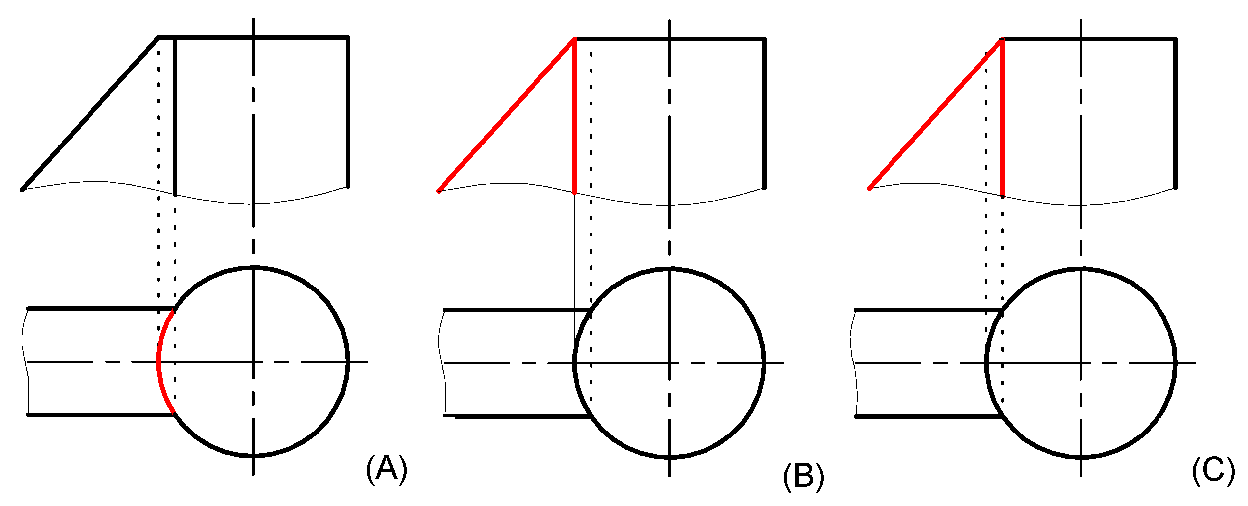
In study case 1, the answer comes back easily since when the students are told that some lines are missing in their front view drawing of the piece, it is not until they are shown a 3D perspective of the lines in question that they finally comprehend the matter. Therefore, the explanation is simple: these students usually have greater difficulties in these subjects due to a lack of spatial visualization abilities. However, after some time of practice, it is also true that some of them are able to develop this skill and procure better results at the end of the course.
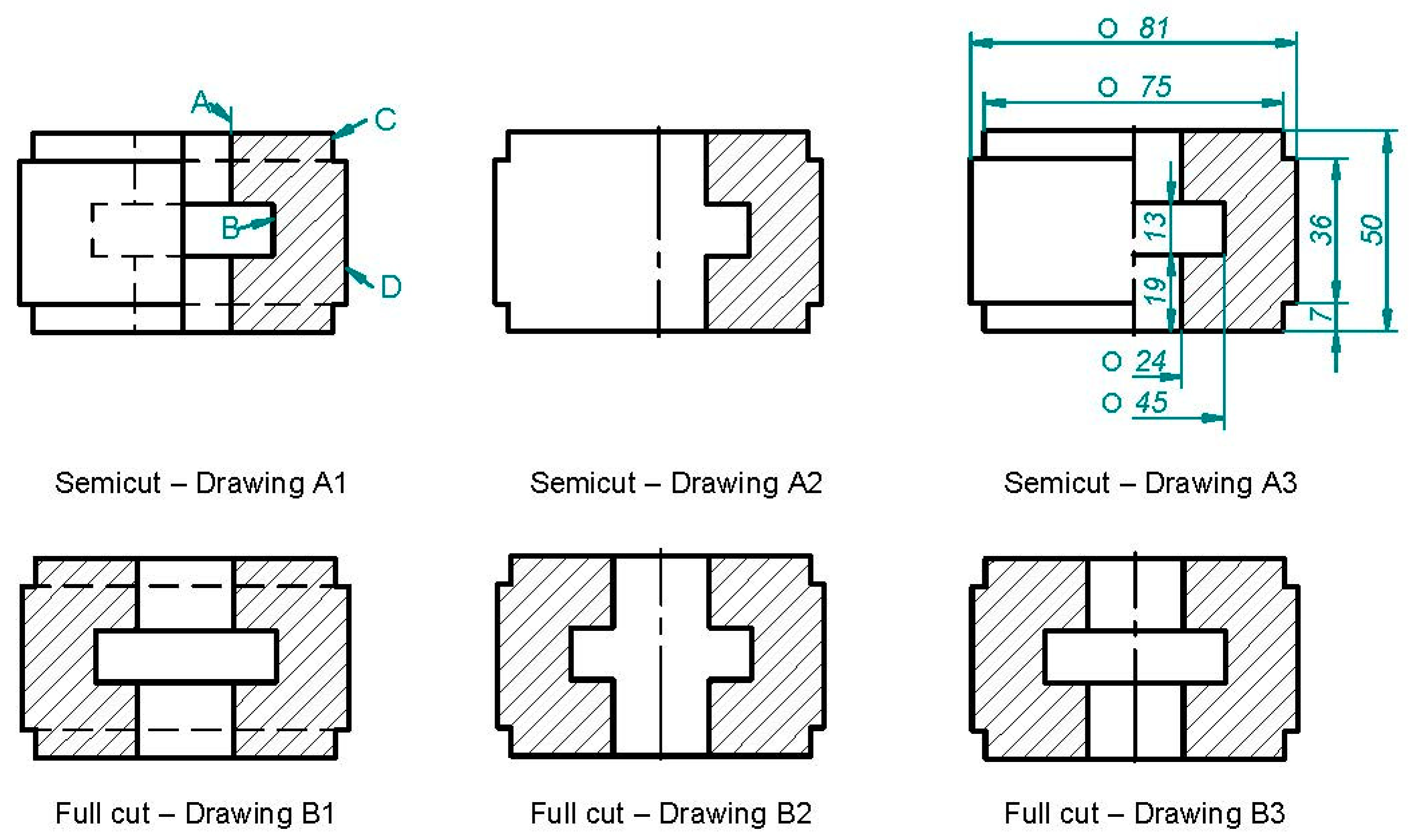
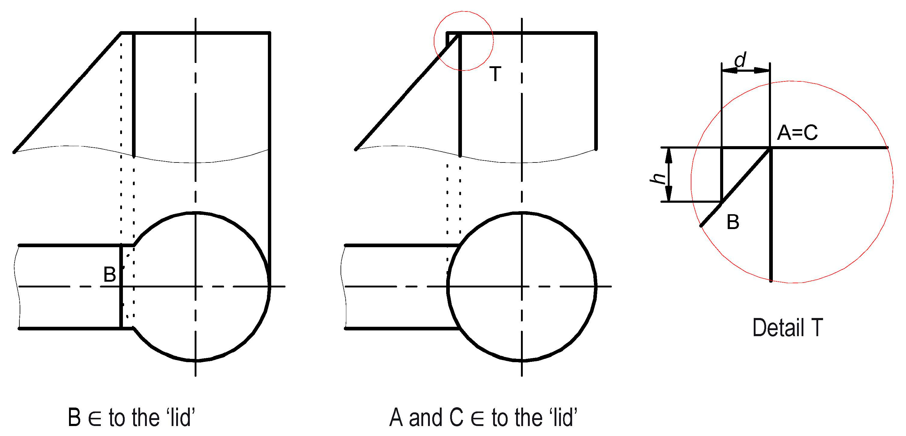
While only a few students fail to draw the front lines in study case 1, in study case 2, most students do not realize what is happening when they receive the error message from the CAD program. They do not stop for a second to think about how the resulting intersection lines will be before executing the standard and automated operation given by the software, which drives us to believe the problem lies in the scarce understanding of descriptive geometry. They take such an impossible intersection as feasible without questioning the practice statement; they simply believe that they are skipping a step in the operation and ask for help in these terms.
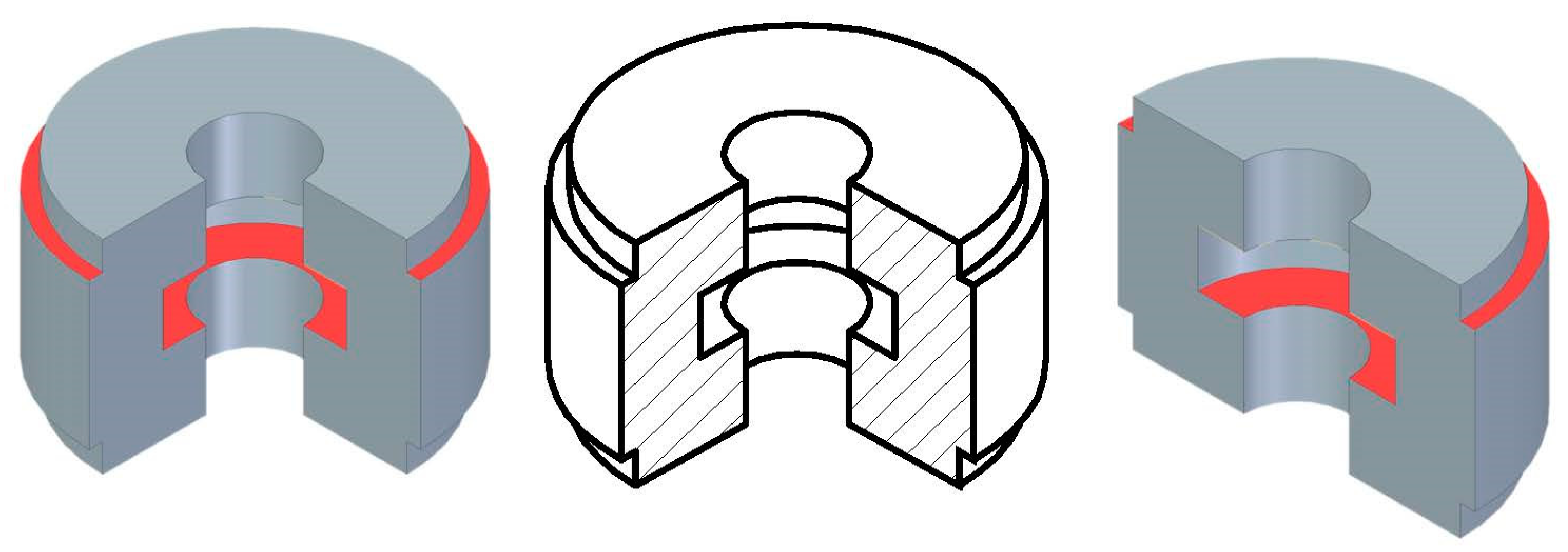
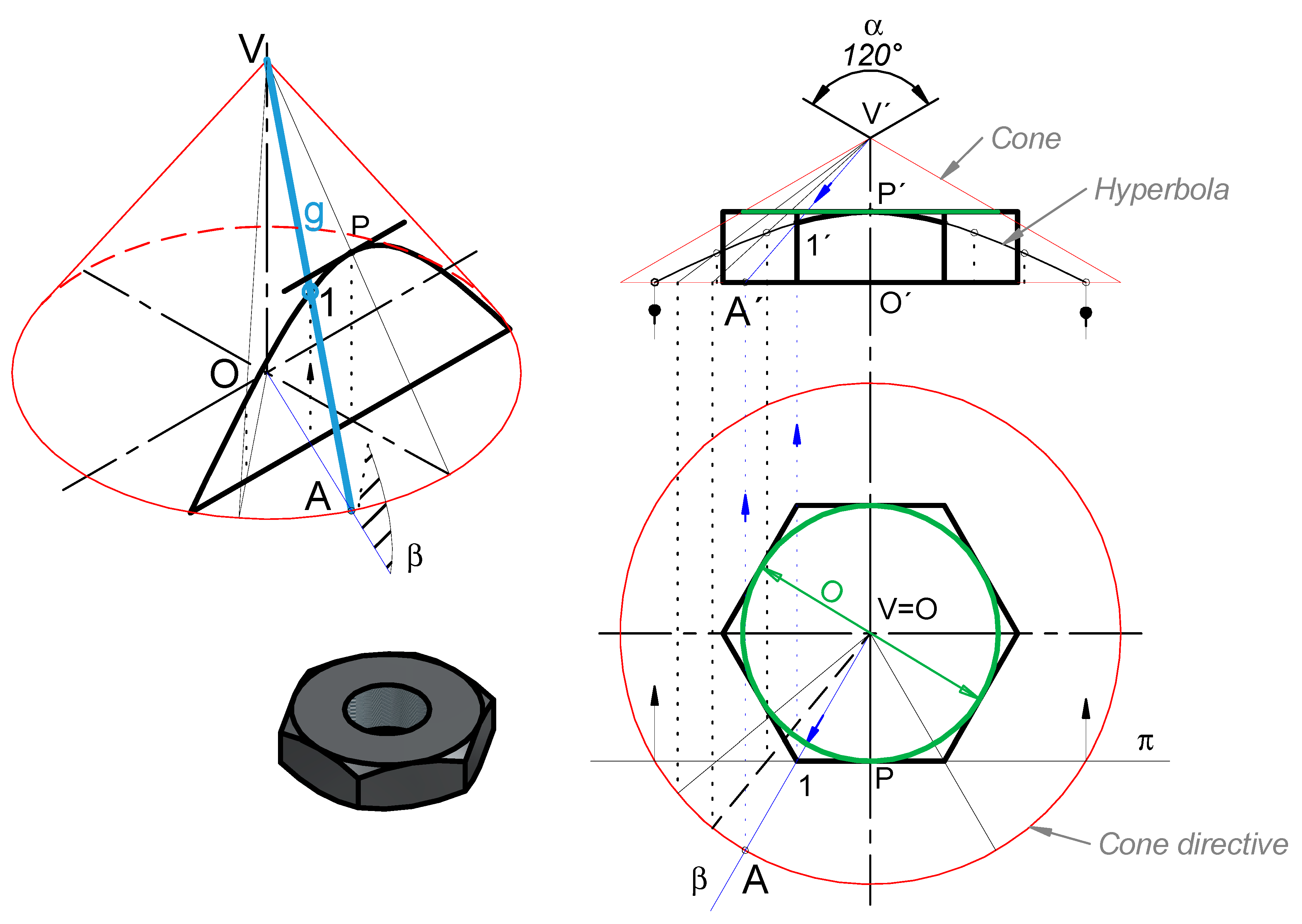
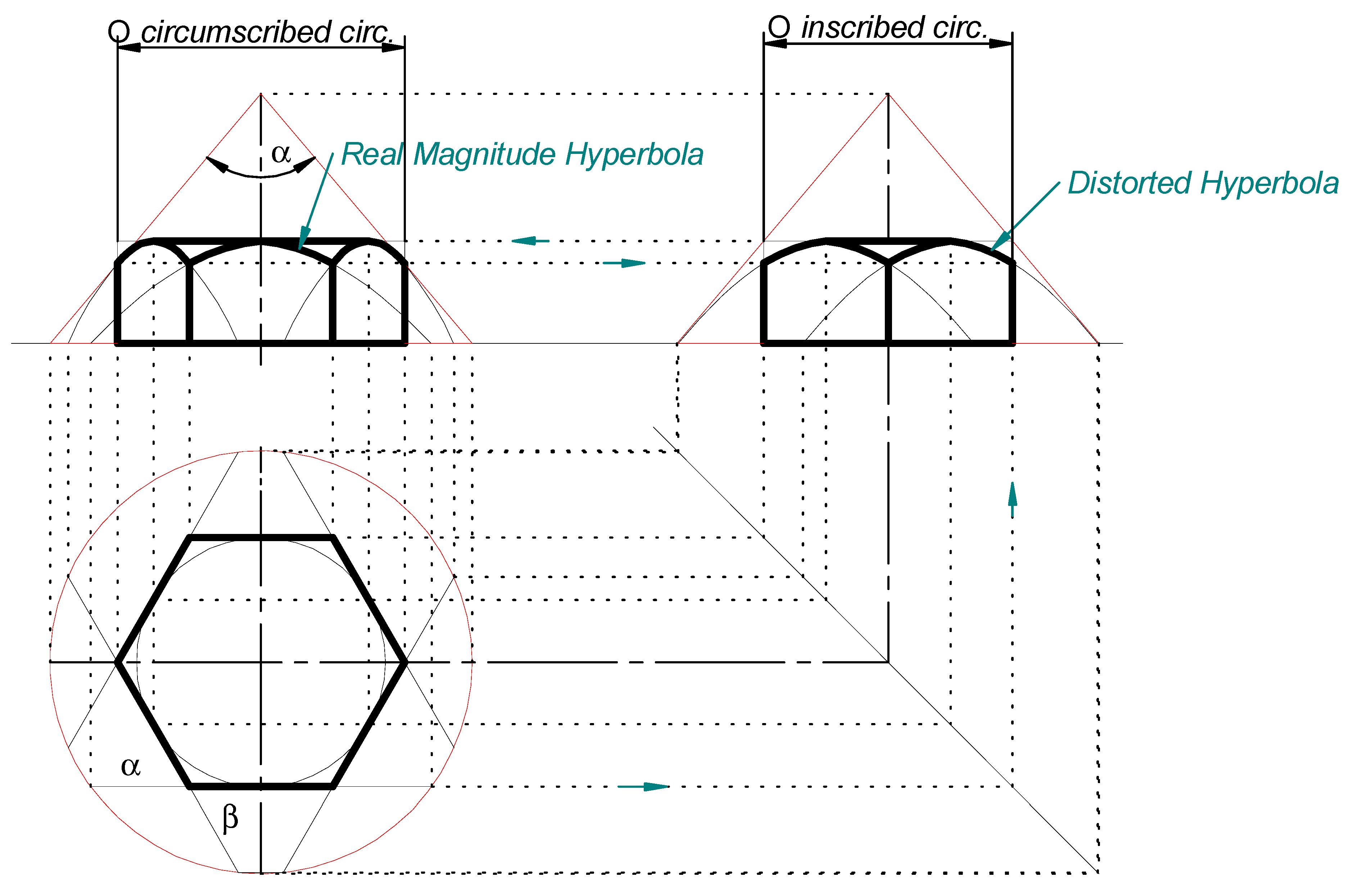
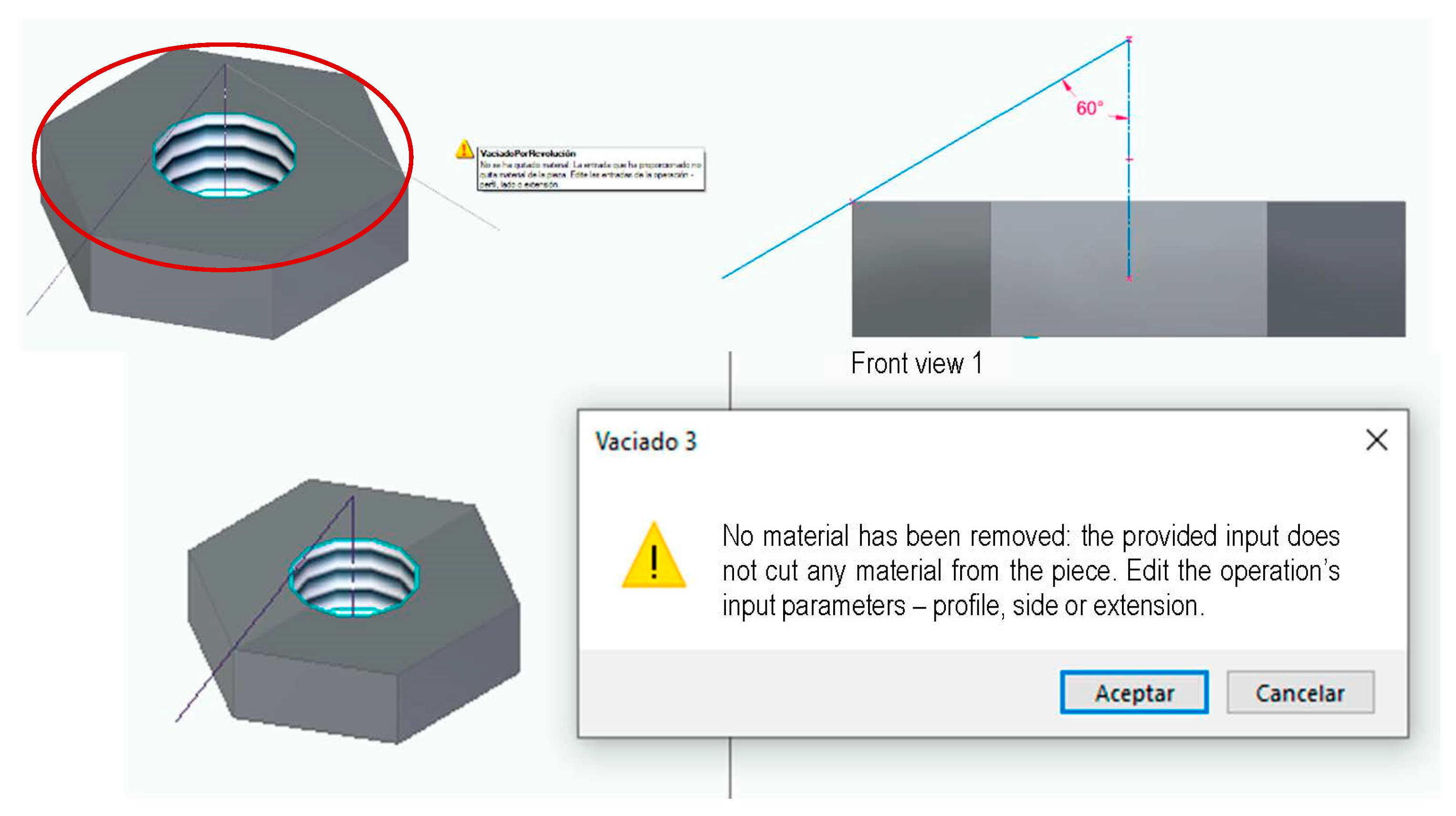
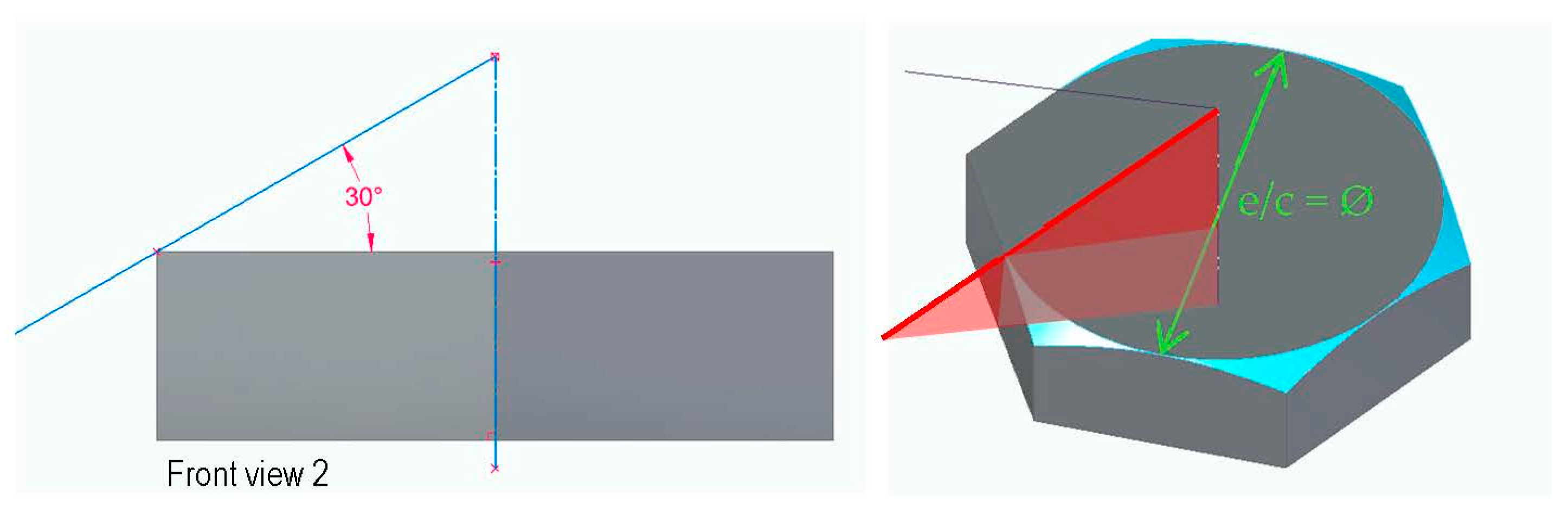
Despite having taken DG courses during their first year at university, students struggle to identify the problem in study case 3 when they locate the cone base circumscribed instead of inscribed in the hexagon upper face, that is to say, making the cone generatrices go through one or the other circumference. When the software displays “no material has been removed: the provided input does not cut material from the piece. Edit the operation’s input parameters—profile, side or extension.” they usually need an explanation from the lecturer to see that they have misplaced the cutting edge in the wrong side of the nut: the hexagon vertex instead of the edge middle point.
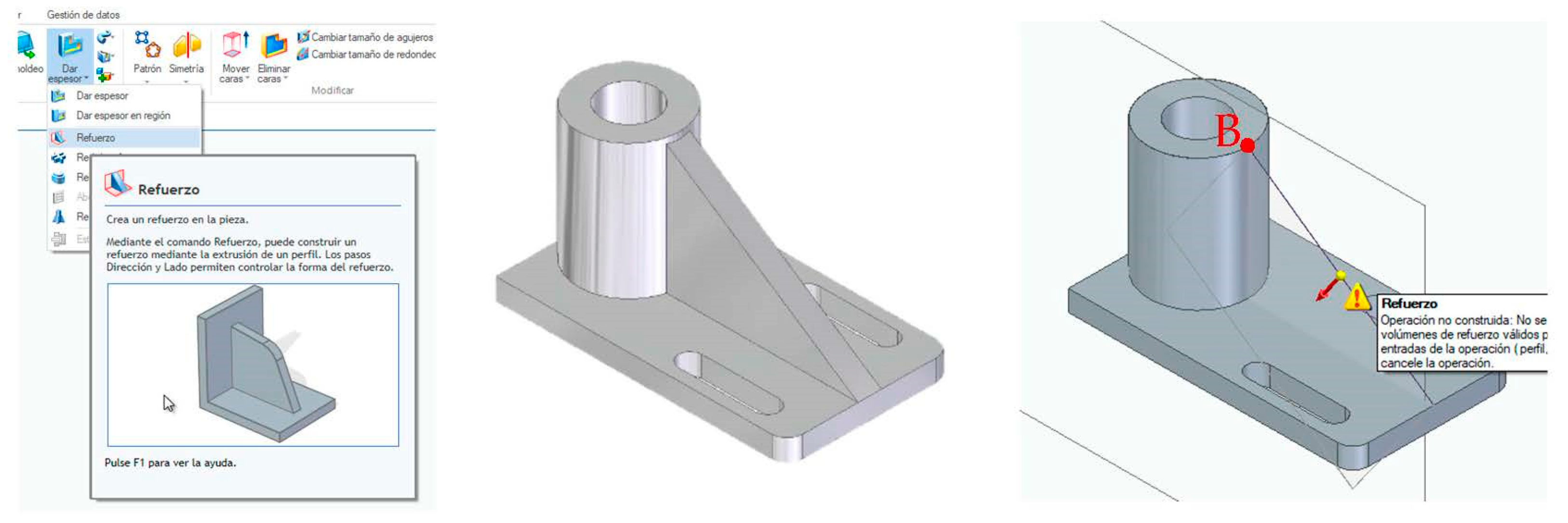
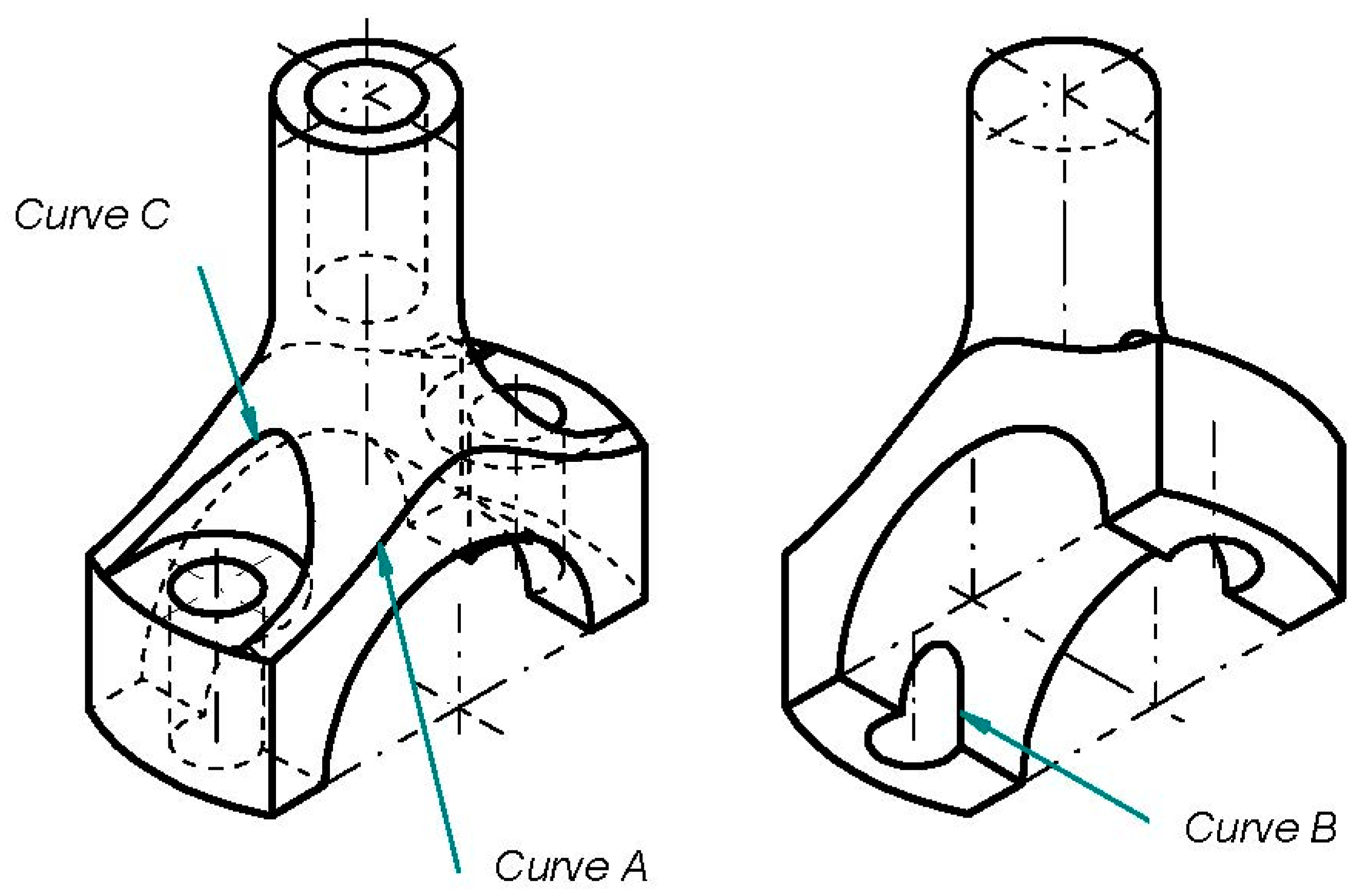
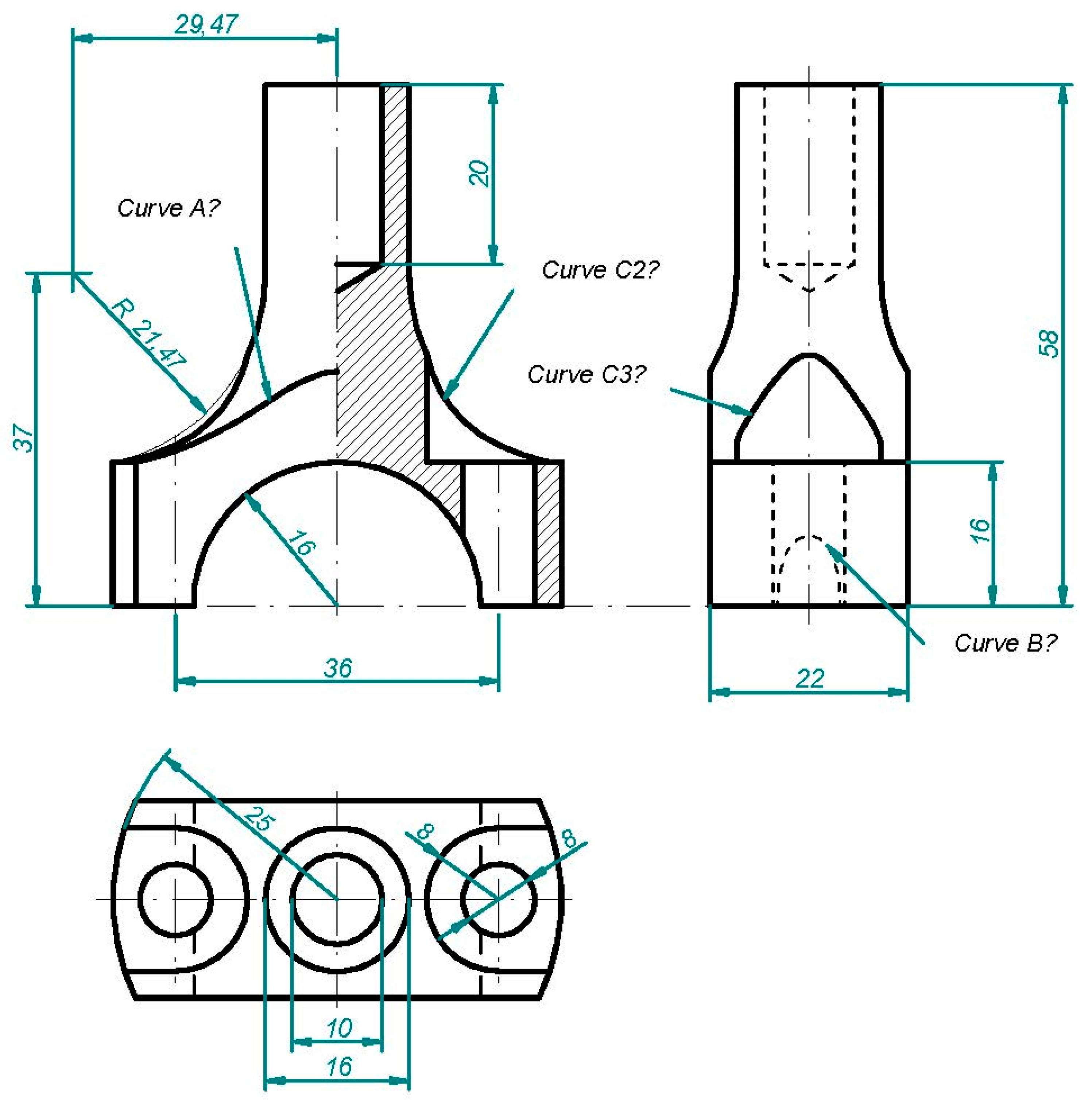
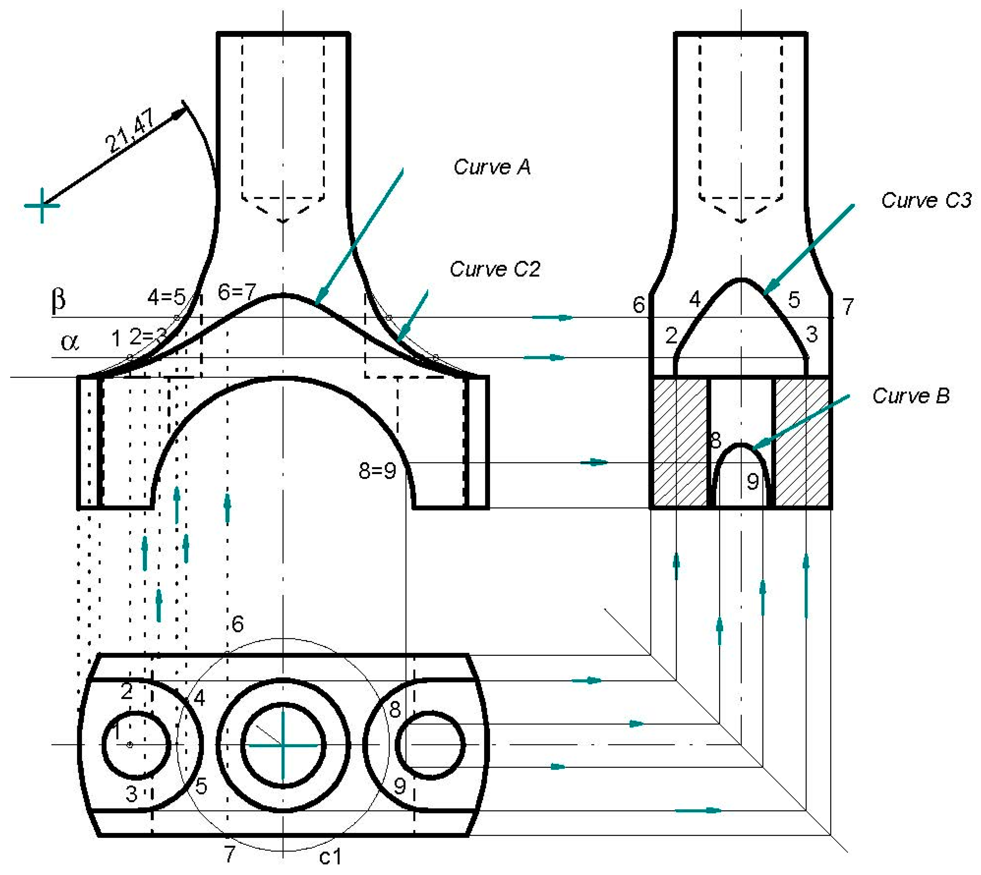
Consequently, if some of them encounter difficulties in modelling pieces from study cases 1–3, the struggle increases exponentially when they come up with parts such as the one presented in study case 4. They truly believe the given drawing lacks some information that would allow the element to be reproduced. The main problem found here is that students often have blind faith in the software employed and do not usually reflect on the error messages received, or what is even more serious, they do not question the solutions the software gives, without thinking about whether the data we have entered are correct, whether we have made a wrong step, or whether the given solution is not what should be expected.
At this point, the significance of attaining a strong grounding in DG together with promoting spatial visualization abilities should be a key factor in training industrial engineers, especially when it comes to CAD, CAM, and CAE processes involved in the ongoing Industry 4.0 and upcoming Industry 5.0.
In recent times, the disproportionate growth of CAD technologies that require almost real-time updating of the tool knowledge employed must not leave aside the capacity to criticize the result sought or obtained, for which it is essential that the engineer’s mind is capable of understanding what is spatially happening before developing it.
Therefore, through the study cases presented in this paper, DG knowledge is proven to be essential and must not be overlooked as old-fashioned or useless; instead, it should be the foundation that allows the tool to be mastered with full potential.
5. Conclusions
The work presented here deals with one of the greatest and most commonly found challenges in the adoption of Industry 4.0: the lack of skills and trained human resources. Among barriers and risks to digital transformation, this is often cited as one of the greatest of all barriers, together with the lack of knowledge of technology and how it can help the company. In these terms, employers often find training and re-skilling staff particularly difficult when adopting new technologies.
More precisely, regarding the CAD–CAM–CAE technology evolution, the introduction of new machines and software over the last few decades has significantly changed the way of operating and interacting with them. In this sense, one of the technologies involved in Industry 4.0 is the use of 3D printing by manufacturers, also called additive manufacturing, to forge parts. This may come together with the employment of digital twins in order to test changes to factory layouts and production lines in computerized models before implementing them. Since technologies linked to 3D simulation keep developing, trained human resources keep developing as well. Establishing the function and skills required by the human factor becomes an integral part of the transition.
One of the skills required in Industry 4.0 related to the world of design, simulation, and manufacturing consists of reaching deep knowledge of the tools to be used. However, two main aspects are somehow hidden underneath the tool knowledge itself. That is to say, in order to attain a well-trained and skilled workforce, deep knowledge of DG and good spatial visualization abilities are demanded so the new software or tools can be employed smoothly. The main discussion on the topic lies in the trend of declaring DG falsely obsolete based on advances in tools led by CAD–CAM–CAE software, while the potential use of new tools and technologies can be truncated and limited by poor knowledge of DG, as the four study cases intend to show in the manuscript.
By means of a descriptive and qualitative analysis of frequently found limitations among industrial engineering students when learning CAD tools, the presented work intends to prove the aforementioned trend about the obsolescence of DG in this field false.
The study cases are chosen for they show the connection between DG and new CAD tool knowledge in an easy, descriptive, and very visual manner, proving that a deep knowledge of the tool or software employed might and shall not be enough to accomplish some of the skills required by Industry 4.0 related to the 3D modeling of products. If the tool knowledge is not backed up by a true understanding of DG concepts, a smooth and controlled operation of the associated software cannot be ensured. These DG concepts might go from very basic knowledge such as recognizing rear elevation lines when going from 3D models to 2D blueprints (study case 1) to anticipating the intersection between two different surfaces or elements to set the right parameters on the tool and avoid error messages from the software due to aiming at impossible outcomes (physically speaking) and the consequent time loss (study cases 2 and 3), or comprehending the origin of certain lines when the input data arrive as 2D blueprints (study case 4). These problems, rooted in the lack of DG concepts, lead to the uncontrolled management of the tool and, therefore, deprived skills in connection with the world of product design, simulation, and manufacturing.
All in all, the paper reflects on the alleged obsolescence of DG and its implications and significance regarding the training and skills of CAD professionals within the field of product design, simulation, and manufacturing towards the Industry 4.0 transition, proving the co-dependence between the optimal performance of CAD tools and the DG knowledge that is needed to back it up.

 ,
, 


