Article

Effects of Large-Diameter Shield Tunneling on the Pile Foundations of High-Speed Railway Bridge and Soil Reinforcement Schemes

1
School of Civil Engineering, Central South University, Changsha 410075, China
2
China Railway Fifth Survey and Design Institute Group Co., Ltd., Beijing 102600, China
*
Author to whom correspondence should be addressed.
Symmetry 2022, 14(9), 1913; https://doi.org/10.3390/sym14091913
Submission received: 17 August 2022 / Revised: 7 September 2022 / Accepted: 9 September 2022 / Published: 13 September 2022

Abstract

:
In order to study the effects induced by large-diameter shield tunneling on the internal force and displacement of adjacent high-speed railway bridge pile foundations, symmetrical element analysis models for the whole process of large-diameter shield tunneling through the high-speed railway bridge were established. The protective effects of various soil reinforcement schemes such as isolation piles’ protection, Metro Jet System (MJS) reinforcement, and the addition of isolated piles’ crown beams were investigated. The numerical results show that the maximum bending moment and the maximum lateral displacement of the bridge piles appear at the piles’ body of the central elevation of the tunnel and the piles’ top, respectively. Without any soil reinforcement measures, the maximum lateral displacement and settlement of the piers top were 7.1 mm and −7.2 mm respectively, which could not meet the displacement control requirements of ±2 mm for the piers of the existing bridge under the condition of the normal operation of high-speed trains. The isolation piles’ protection effect was better than that of MJS reinforcement alone. Two or more soil reinforcement measures could be adopted simultaneously to further control the displacement of piers within ±1 mm. The validity of the numerical simulation results was verified by comparing them with the field monitoring results.

1. Introduction

By the end of 2021, China’s high-speed railway operating mileage has reached 40,000 km, ranking first in the world, of which bridges account for a relatively high proportion in China’s high-speed railway network. With the rapid development of the integrated transportation network of urban agglomeration, roads, subways, and municipal engineering projects are growing at a rate of more than 200,000 km per year. Soft soil is widely distributed in China, and China’s high-speed railway has the characteristics of too many lines, high traffic density, and high operation speed. The increasingly large-scale and networked roads, subways, and municipal engineering will inevitably encounter shield tunneling through high-speed railway bridges. The large-diameter shield construction will disturb the surrounding soil to a greater extent, causing the displacements of the adjacent high-speed railway bridge pile foundations. On the one hand, it will produce additional internal force and displacements of the bridge piles, on the other hand, the displacements of the bridge piers will aggravate the irregularity of the track on the bridge, which may affect the operation safety of high-speed trains. Therefore, it has become an important and urgent issue to research the effects of large-diameter shield tunneling on the pile foundations of adjacent high-speed railway bridges.
Many scholars have carried out a lot of research on the effects of shield construction on adjacent pile foundations. Chen [1] used a two-stage analysis method to analyze the lateral and vertical displacement of a single pile induced by tunneling. Jacobsz et al. [2,3] studied the effects of tunneling in dry sand on the displacement of the adjacent single pile by centrifugal tests. Ng et al. [4] further studied the effects of twin tunneling on pile groups by a series of three-dimensional centrifuge tests. Based on the two-stage analysis method, Basile [5] proposed a more effective analysis method to estimate the internal force and displacement of pile groups caused by tunneling. Yoo et al. [6,7] used a numerical analysis method to study the effects of shield tunneling on adjacent bridge pile foundations. Other scholars have verified their numerical calculation results in combination with centrifuge models test results [8,9,10,11] or field monitoring data [12,13,14,15]. In order to reduce the disturbance of the surrounding soil layer induced by tunneling and ensure the stability and safety of the existing structure, necessary protective measures should be taken for the existing pile foundation before tunneling. Wang [16] studied the control effect of soil grouting reinforcement on the additional deformation and internal force of existing pile foundations. Liu et al. [17,18,19] studied the protective effect of isolation piles on existing bridge pile foundations. Wu et al. [20,21,22] compared and analyzed the control effects of isolation piles’ protection and grouting reinforcement on pile foundation displacement. Li et al. [23,24,25] explored the protective effect of MJS reinforcement using finite element numerical analysis. It can be seen that the current research is mainly focused on small-diameter shield tunneling through railway bridges or highway bridges, and there are also some studies on large-diameter shield tunneling through highway bridges, but there are relatively few studies on large-diameter shield tunneling through high-speed railway bridges. To ensure the normal operation of high-speed trains during the construction of large-diameter shield tunneling through high-speed railway bridges, it is not only necessary to control the internal force of the pile foundation of the high-speed railway bridge, but also strictly limit the displacements of bridge piers. Generally, various soil reinforcement measures are adopted simultaneously: isolation piles’ protection, MJS reinforcement, and the addition of isolated piles’ crown beams, etc.
In this paper, on the basis of the practice of the Tongjing Road North Extension Project in Suzhou, finite element analysis models for the whole process of 13.76 m large-diameter shield tunneling through the high-speed railway bridge were established by using finite element software ANSYS. Firstly, the effects induced by large-diameter shield tunneling on the internal force and displacement of adjacent high-speed railway bridge pile foundations were analyzed. Secondly, the protective effects of isolation piles’ protection, MJS reinforcement, and adding isolated piles’ crown beams were studied. Finally, compared with the field test results, the numerical simulation results were verified. The current study can provide a reliable reference for the design and construction of similar shield tunneling projects, and also provide a basis for further research on the optimization design of existing reinforcement schemes.

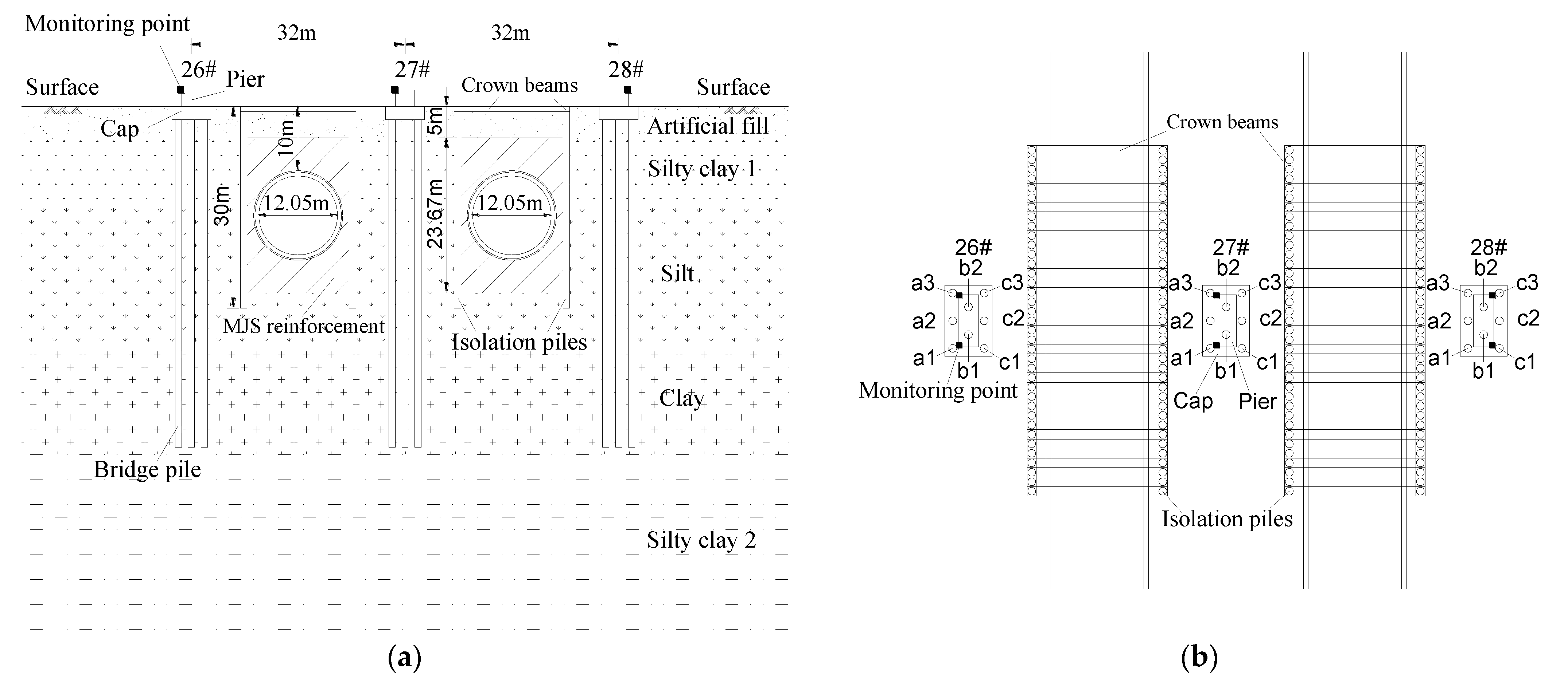
2. Overview of the Engineering

The north extension project of Suzhou Tongjing road starts from the South Bank of the Xitang River. To the south, the shield tunnel section passes through the Shantang River and the historical and cultural buildings on both sides, the Shanghai-Nanjing high-speed railway, the existing Beijing-Shanghai railway, and the North Ring Expressway, with a total length of 490 m. The section where the shield tunneling through the multi-span 32 m simply supported beam bridge of the Shanghai-Nanjing high-speed railway is the key control project. The 27# pier is located in the middle of the twin tunnels. The distance between the twin tunnels is 32.76 m, and the buried depth of the tunnels is about 10 m. The tunnels are excavated by a mud-water balance shield machine with a cutter head diameter of 13.67 m. The construction sequence is the left line first and then the right line. The tunnel segment is circular with an outer diameter of 13.25 m and an inner diameter of 12.05 m, and its concrete grade is C50. The section size of the bridge piers is 7 m × 3 m × 2.5 m, and the size of the pile caps is 9 m × 6 m × 2 m. The diameter of the bridge piles is 1 m, and the piles’ length is about 50 m. The concrete grade of the piers, piles, and caps is C35. In the section where the shield tunneling affects the existing railway bridge, the actual project adopts isolation piles’ protection and MJS reinforcement at the same time, and crown beams are added at the top of the isolation piles. The reinforcement area is left-right symmetrical and front-to-back symmetrical. The length of the reinforced area along the tunnel excavation direction is about 45 m, as shown in Figure 1. The isolation piles are arranged on both sides of the shield tunnel. The diameter of the isolation piles is 1 m, the distance between adjacent isolation piles is 1.2 m, and the length of the isolation piles is 30 m. The section size of the isolation piles’ crown beams is 1.2 m × 0.8 m. The concrete grade of isolation piles and crown beams is C30. The upper and lower boundaries of the MJS reinforcement area are 5 m away from the outer contour of the tunnel, and the left and right boundaries are 1 m away from the outer contour of the tunnel.

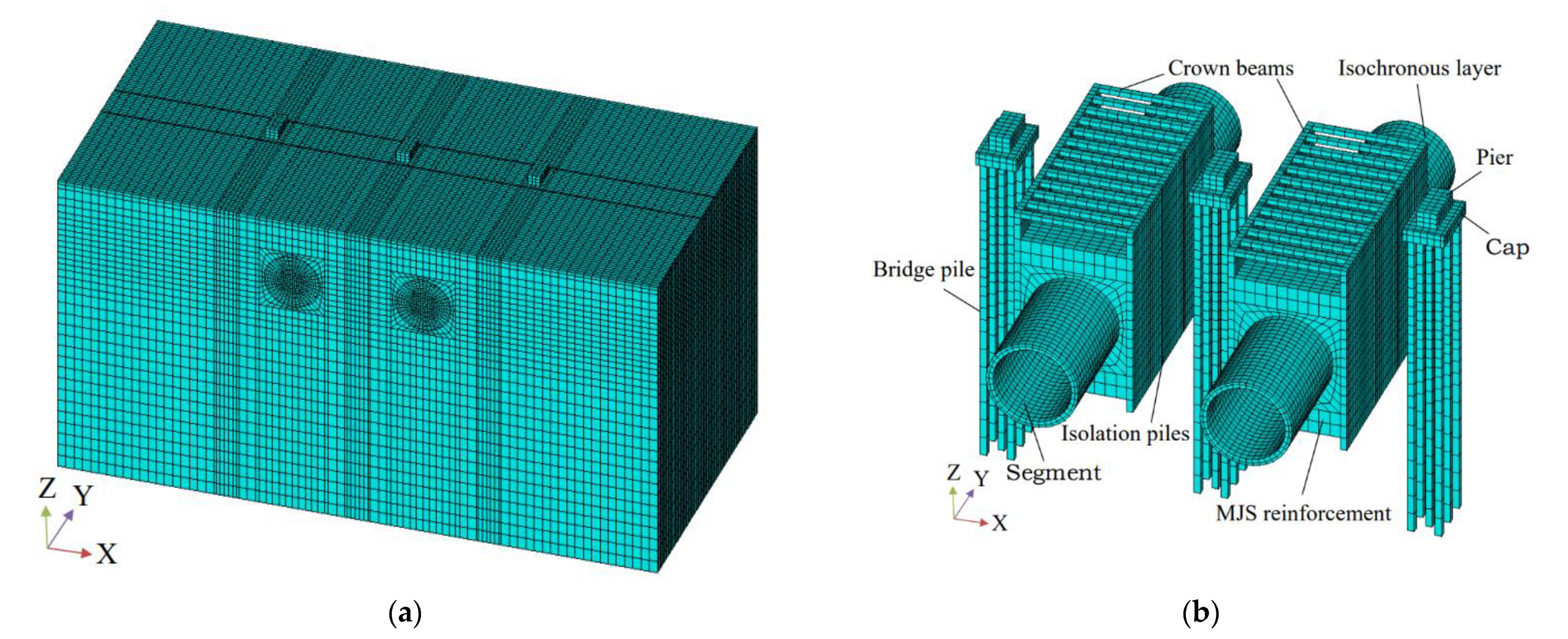
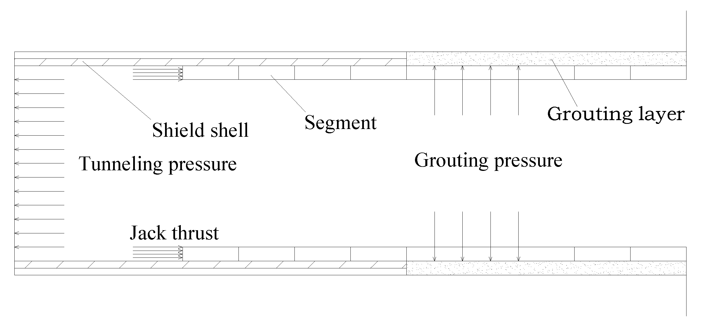
3. Symmetrical Finite Element Models

In order to study the effects induced by large-diameter shield tunneling on the internal force and displacement of adjacent high-speed railway bridge pile foundations, based on the practice of the Tongjing Road North Extension Project in Suzhou, the symmetrical finite element analysis models of the whole process of shield tunneling with a diameter of 13.67 m were established. The three-dimensional finite element model is shown in Figure 2. The soil layers, shield shell, segment, piers, pile foundations, isolation piles, isolated piles’ crown beams, and MJS reinforcement were simulated by SOLID45 element, the pile-soil interaction was simulated by contact elements TARGE170 and CONTA173 elements, and the friction coefficient was taken as 0.3. The shield tail gap and the slurry filling in the gap were simplified into a homogeneous and equal thickness isochronous layer, and the SOLID45 element was also used to simulate the slurry hardening process by setting the elastic modulus of the isochronous layer element to change with time [26,27].
The boundary conditions were set as follows: the top side is a free surface, the four side surfaces restrain its normal displacement, and the bottom surface restrains the displacement in three directions. In order to eliminate the influence of the boundary constraint effect, the boundary interface of the numerical model can be taken to 3–5 times the tunnel diameter. The size of the models is 150 m × 90 m × 80 m (X × Y × Z). The X-axis direction is the tunnel radial direction, the Y-axis direction is the tunnel excavation direction, and the Z-axis direction is the vertically downward direction. The dimension of the caps along the tunnel excavation direction is 9 m, which is recorded as b. The vertical plane of the bridge centerline is taken as y/b = 0. Therefore, the shield tunneling process is from section y/b = −5 to section y/b = −5. That is to say, the whole construction process of shield tunneling through the high-speed railway bridge from the cutter head to −45 m from the bridge centerline to +45 m across the bridge centerline was considered, in which the −22.5 m to +22.5 m section along the Y-axis direction is the range of soil reinforcement. To accurately simulate the whole process of shield construction, the loads that can be considered mainly included the dead weight of the structures, the tunneling pressure of 200 kPa (acting on the excavation face), the jack thrust of 65 MN (acting on the segment) and the grouting pressure of 200 kPa (acting on the segment and surrounding soil at the same time). A uniform surface pressure of 380 kPa (calculated according to the dead weight of the simply supported beams) was applied to the top surface of the bridge piers to simulate the dead weight of the bridge. The process of soil stress release and excavation was simulated by changing the material stiffness and the active state of finite elements (i.e., the life and death state of finite elements). The schematic diagram of the shield tunneling process is shown in Figure 3. The twin tunnels are excavated step by step from south to north, and the excavation length of each step is 1.5 m, with the left line first and then the right line. The whole construction process is divided into 120 excavation steps.
In ANSYS finite element software, the ideal elastic–plastic constitutive model is used to simulate the stress–strain relationship of soil materials, and its failure criterion is the Drucker–Prager failure criterion. The Drucker–Prager failure criterion is a three-dimensional pressure-dependent model to estimate the stress state at which the soil reaches its ultimate strength. The Drucker–Prager failure criterion was established as a generalization of the Mohr-Coulomb criterion for soils [28], which can be expressed as [29]:
J 2 = α J 1 + β
where α and β are material constants, J 2 is the second invariant of the stress deviator tensor and J 1 is the first invariant of the stress tensor, and are defined as follows:
α = 2 sin θ 3 3 sin θ
β = 6 c cos θ 3 3 sin θ
J 1 = σ 1 + σ 2 + σ 3
J 2 = 1 6 σ 1 σ 2 2 + σ 2 σ 3 2 + σ 3 σ 1 2
where c and θ are the cohesion intercept and internal friction angle of the soil; σ 1 , σ 2 and σ 3 are the principal effective stresses.
Due to the too small inclination of each soil layer, they can be approximately considered horizontal soil layers. At the same time, considering a large number of soil layers and the small difference between the properties and physical and mechanical parameters of adjacent soil layers, the adjacent soil layers are merged. The physical and mechanical parameters of the merged soil layers and MJS reinforcement are shown in Table 1. The compression modulus in the table is the ratio of stress to strain when the soil is compressed under confined conditions. The value was determined by a series of soil consolidation tests. The physical and mechanical parameters of the structures are shown in Table 2.

4. Effects of Shield Tunneling on Adjacent Pile Foundations

Under the condition of undisturbed soil layers, that is, without any reinforcement measures, the static calculation and analysis of adjacent bridge piles during the whole construction process of shield tunneling through high-speed railway bridges were carried out, and the effects of shield tunneling on the bending moment and displacement of adjacent bridge pile foundations were studied.

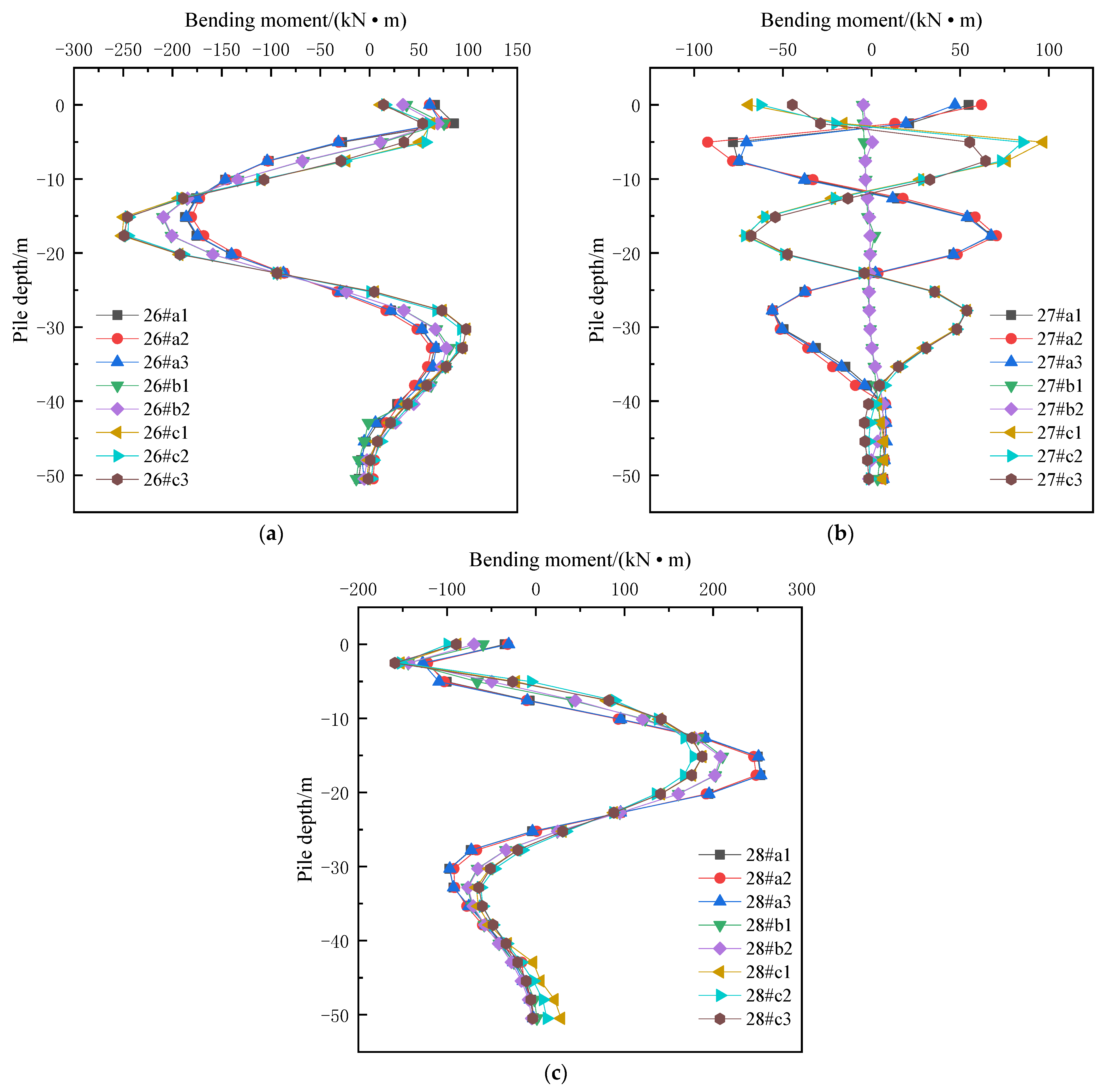
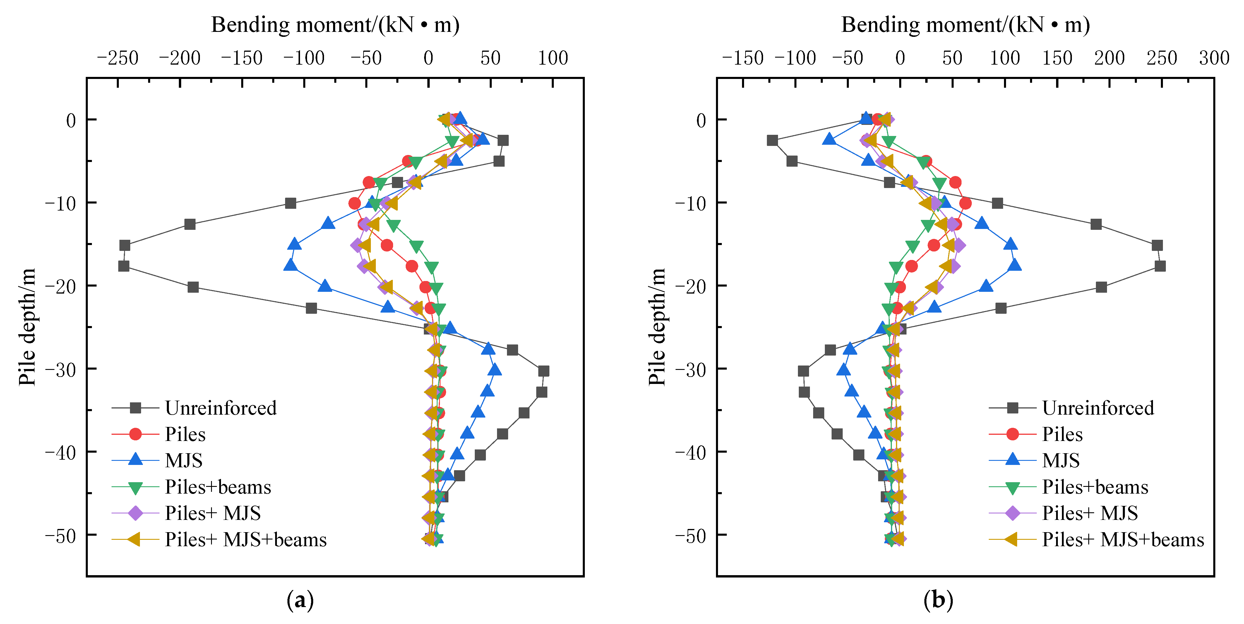
4.1. Effects of Shield Tunneling on Bending Moment of Adjacent Bridge Piles

Figure 4 shows the bending moment of the piles’ body that causes the bridge piles to bend along the bridge direction (i.e., X-axis direction) after the excavation of the twin tunnels is completed without soil reinforcement (i.e., undisturbed soil layer). The bending moment diagram is drawn on the tensile side of the piles’ body, that is, when the bending moment is positive, it indicates that the right side of the piles’ body is in tension, and when the bending moment is negative, it indicates that the left side of the piles’ body is in tension. It can be seen that the bending moment distribution law of all bridge piles under the 26#cap on the left side of the twin tunnels was similar along the piles’ bodies. That is, at the elevation above the tunnel crown or below the tunnel bottom, the bridge piles mainly produced a positive bending moment; at the elevation from the tunnel crown to the tunnel bottom, the bridge piles mainly produced a negative bending moment; and the maximum bending moment value was generated at the pile body at the same height as the center of the tunnels. The closer to the tunnel, the greater the maximum bending moment of the bridge piles. The bending moment distribution law of all bridge piles under the 28#cap on the right side of the twin tunnels was basically symmetrical with that of the 26#cap, indicating that the distribution law of the bending moment of the pile group under the caps located outside the twin tunnels was consistent along the piles’ body. The bending moment of the pile body in the middle row of piles (row b) under the 27#cap in the middle of the twin tunnels was almost zero, while the bending moment values of the other two rows of piles (row a and row c) alternated positively and negatively along the pile’s body. The bending moment distribution law of the row 27#a piles was basically symmetrical with that of the row 27#c piles. Comparing the bending moment values of all bridge piles, the bending moment of piles under the caps outside the twin tunnels was similar and greater than that under the cap between the twin tunnels. The maximum bending moment occurred on the piles (rows 26#c and 28#a) near the tunnels under the caps outside the twin tunnels. This is because the piles located on the same side of the twin tunnels were affected by the excavation of the twin tunnels in a similar manner, and will only be affected to different degrees by the distance, but the piles located between the twin tunnels were affected by the excavation of the twin tunnels to the opposite manner, resulting in positive and negative superposition effects.

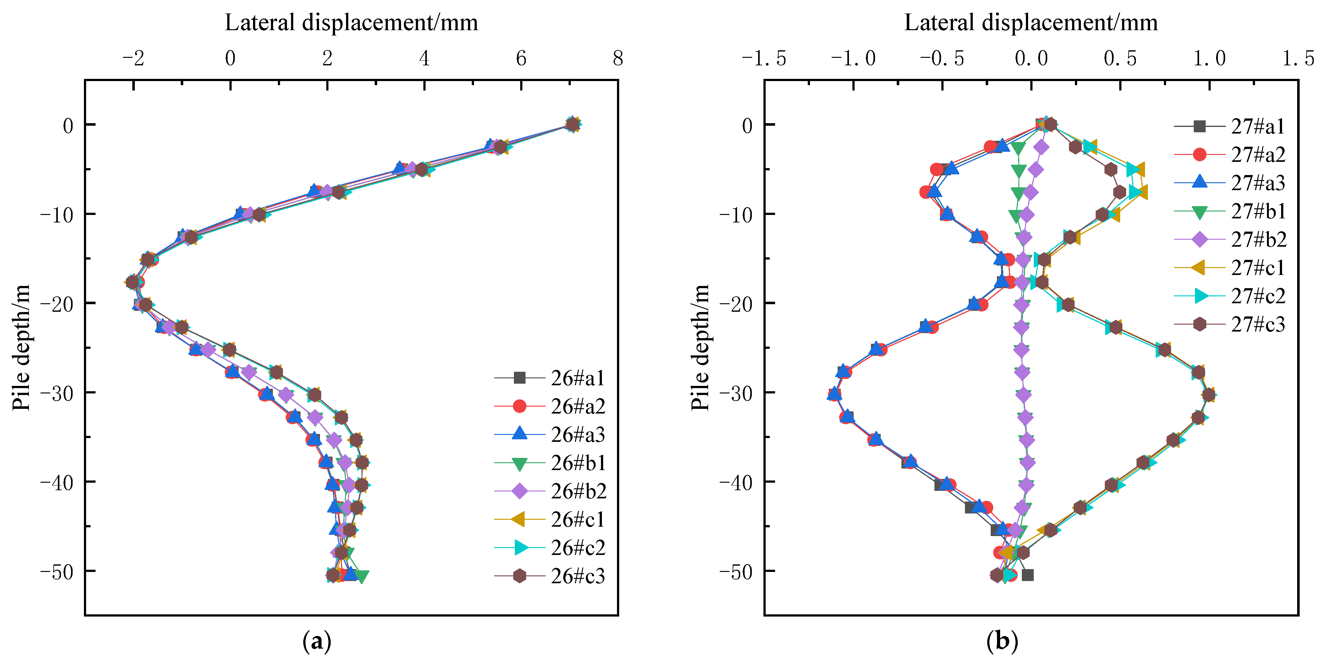
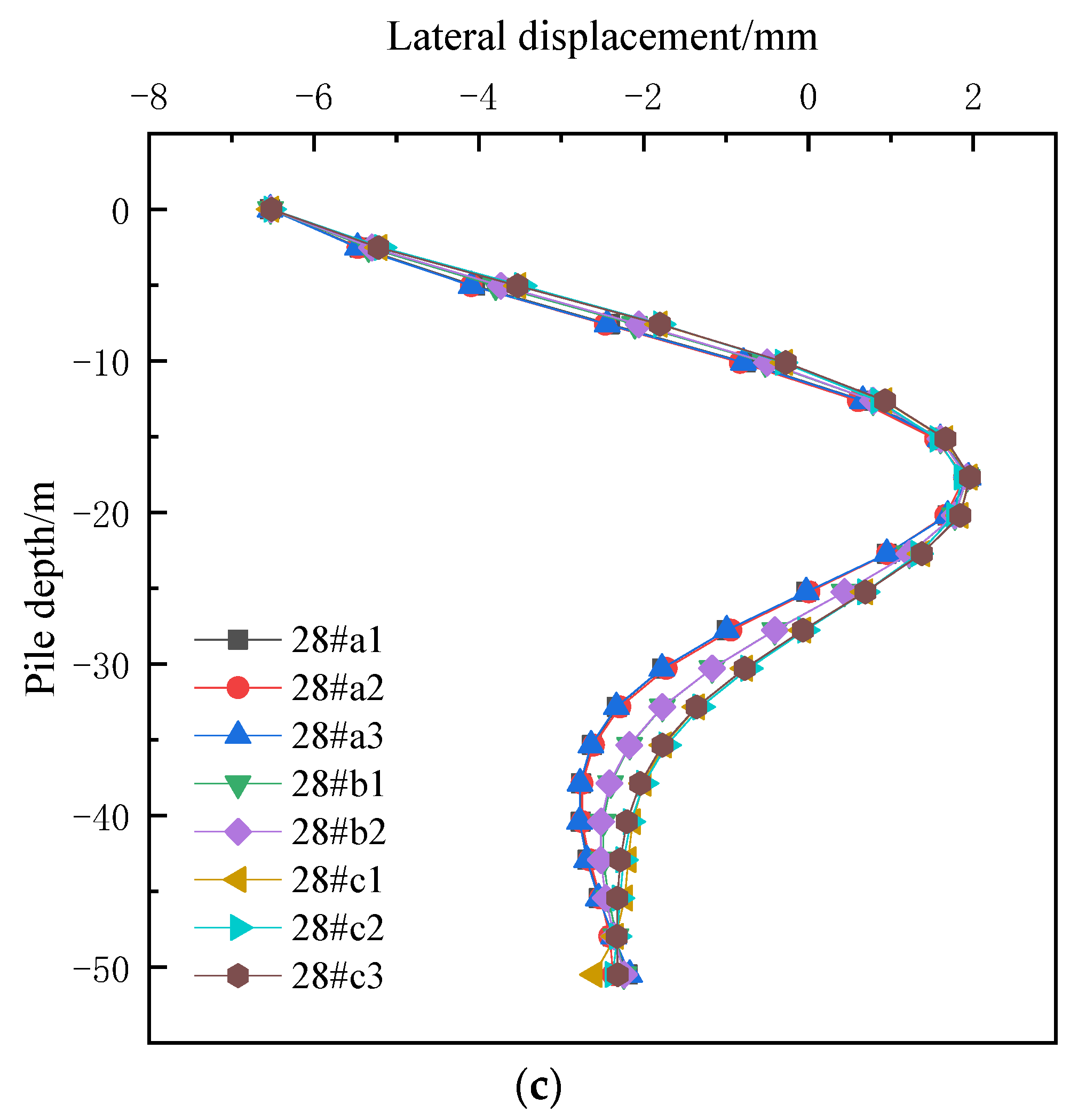
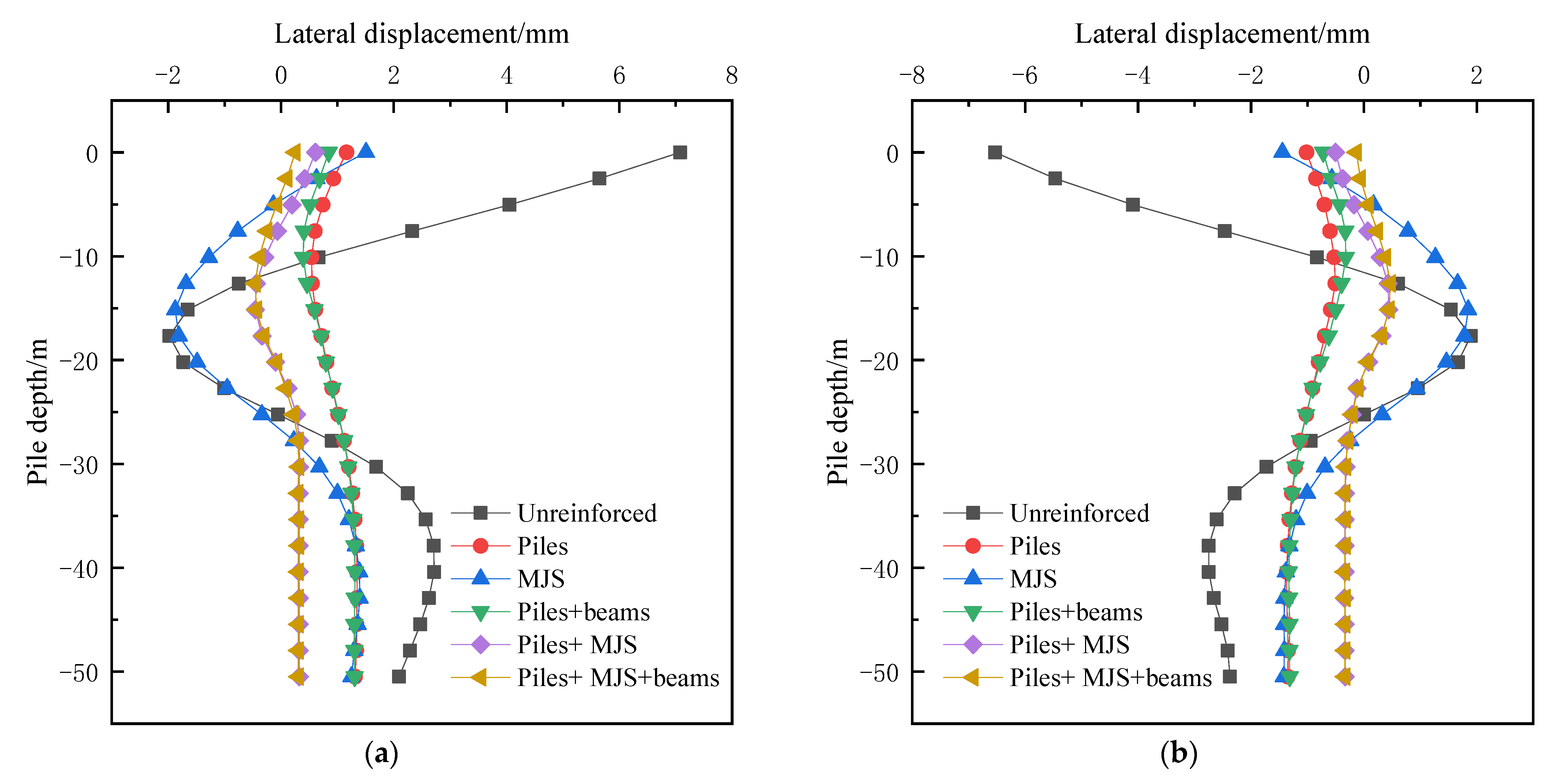
4.2. Effects of Shield Tunneling on the Displacement of Adjacent Pile Foundations

Figure 5 shows the lateral displacement of bridge piles under each cap after the excavation of the twin tunnels was completed without soil reinforcement (i.e., undisturbed soil layer), and the displacement was positive when it pointed to the right. The lateral displacement of the piles under the caps (i.e., 26 # and 28 #) on the outside of the twin tunnels was basically symmetrical along the piles’ bodies. At the elevation above the tunnel crown or below the tunnel bottom, the bridge piles outside the twin tunnels mainly produced lateral displacement with direction pointing to the tunnel. At the elevation from the tunnel crown to the tunnel bottom, the bridge piles outside the twin tunnel mainly produced lateral displacement with directions away from the tunnel. The similar deformation law of bridge piles is found in reference [17]. The reason for the horizontal displacement distribution law is: that the vertical pressure of soil is usually greater than the lateral pressure, so the supporting structure is “flattened”, the crown and bottom of the tunnels move inward, and the soil outside is relaxed, while the left and right sides of the tunnel move outward, and the soil outside is squeezed (as shown in Figure 6); coupled with the timely application of the supporting structure, the “free deformation” of the tunnels is small, then the final displacement direction of the left and right sides of the tunnels is outward compared with the initial position [30]. At the same elevation, the lateral displacement of the same row of piles under the caps outside the twin tunnels is almost the same, and there is only a slight difference in the lateral displacement of different rows of piles. The phenomenon is consistent with the conclusion of the literature [31]. The lateral displacement value at the piles’ top was the largest. The lateral displacement distribution law of all bridge piles under the 26#cap on the right side of the twin tunnels was basically symmetrical with that of the 28#cap. The lateral displacement of the middle bridge piles (i.e., row b) under the 27#cap located between the twin tunnels was almost zero, while the left bridge piles (i.e., row a) mainly produce displacement pointing to the left tunnel, and the right bridge piles (i.e., row c) mainly produced displacement pointing to the right tunnel. The lateral displacement distribution law of the row 27#a piles was basically symmetrical with that of the row 27#c piles. Due to the high stiffness of the cap itself, the bridge piles under the same cap generated the same lateral displacement at the top.
Figure 7 shows the cloud diagram of the settlement of the pile foundations after the excavation of the twin tunnel was completed without soil reinforcement (i.e., undisturbed soil layer), and a negative value means that the pile foundations sink downward. After the tunnel excavation was completed, the adjacent pile foundations sank, mainly because after the soil was excavated, the earth stress around the tunnel was released, and the soil above the tunnel sank, driving the nearby pile foundations to sink. The settlement of the same bridge pile along the pile body changes little, and the closer the bridge pile is to the tunnel, the greater the settlement. There are small differences in the settlement of different positions on the same pile cap and pier, and the settlement of the side closer to the tunnel was larger. The settlement value of pile foundations and piers in symmetrical positions were almost the same. The maximum settlement of the tops of the three piers was −4.7 mm, −7.2 mm, and −4.6 mm, respectively, which could not meet the settlement control requirements of ±2 mm for the piers of the existing high-speed railway under the condition of unlimited train speed [32]. To ensure the normal operation of high-speed railway trains during the shield tunneling construction, reinforcement measures must be taken for the surrounding soil layer of the tunnels before the shield enters the affected section of the railway.

5. Analysis of the Effects of Soil Reinforcement Schemes

In order to study the control effects of soil reinforcement schemes such as isolation piles’ protection, MJS reinforcement and the addition of isolated piles’ crown beams on existing adjacent pile foundations and piers displacements, when carrying out the static calculation of internal force and displacement of adjacent pile foundations during the shield tunneling through the high-speed railway bridge, in addition to considering the undisturbed soil layer (i.e., without soil reinforcement, abbreviated as Unreinforced), five soil reinforcement schemes including isolation piles’ protection (abbreviated as Piles), MJS reinforcement (abbreviated as MJS), isolation piles + crown beams (abbreviated as Piles + beams), isolation piles + MJS reinforcement (abbreviated as Piles + MJS), isolation piles + MJS reinforcement + crown beams (abbreviated as Piles + MJS + beams) are also considered. The numerical results of bending moment and displacement of adjacent bridge pile foundations during the whole process of shield tunneling under different soil reinforcement conditions were obtained. Since the internal force and displacement of the piles under the caps (i.e., 26 # and 28 #) on the outside of the twin tunnel were relatively large, the 26#c2 and 28#a2 piles closest to the tunnels and below the centerline of the bridge were selected as examples. The bending moment and displacement of the bridge piles after the completed excavation of the twin tunnels are shown in Figure 8 and Figure 9, respectively. The results of the maximum bending moment of the bridge piles and the maximum displacement of the bridge piers are listed in Table 3. As can be seen:
(1)
Without any soil reinforcement measures, the maximum bending moment of the bridge piles was 248 kN · m, the bending deformation of the bridge piles was large, the maximum lateral displacement of the top of the piers was 7.1 mm, and the maximum settlement of the middle pier top was −7.2 mm. Since they cannot meet the displacement control requirements of ±2 mm for the piers of the existing high-speed railway under the condition of unlimited train speed, reinforcement measures must be taken for the soil layers in the affected section in advance before the construction of large-diameter shield tunneling through the high-speed railway bridge.
(2)
After five soil reinforcement schemes including isolation piles’ protection, MJS reinforcement, isolation piles + crown beams, isolation piles + MJS reinforcement, and isolation piles + MJS reinforcement + crown beams were adopted respectively, the maximum bending moment of the bridge piles was −111 kN · m, the bending deformation of the bridge piles was greatly reduced, the maximum lateral displacement of piers top was 1.5 mm, and the maximum settlement of middle pier top was −1.8 mm. Therefore, these five soil reinforcement schemes had obvious protective effects on adjacent pile foundations, and could significantly reduce the maximum bending moment, lateral displacement, and settlement of pile foundations.
(3)
When isolated piles were adopted for protection alone, the maximum bending moment of bridge piles was 62 kN · m, the maximum lateral displacement of the top of the piers was 1.2 mm, and the maximum settlement of the middle pier top was −1.2 mm. The control effect was better than that of MJS reinforcement alone, so isolation pile protection should be preferred.
(4)
Compared with isolated piles’ protection alone, the bending moment and lateral displacement of bridge piles could be further reduced by using isolated pile + crown beams protection at the same time, but the effect on the maximum bending moment of the bridge piles was relatively small.
(5)
After five soil layer reinforcement schemes were adopted respectively, the lateral displacement and settlement of the top of the piers could be controlled within ± 2 mm, which could meet the structural deformation control requirements specified during the construction of shield tunneling through high-speed railway bridges. Considering the economy of the construction cost and the effects of soil reinforcement, isolation pile protection should be preferred. In order to ensure the absolute safety of high-speed train operation during shield tunneling, it is recommended to adopt the reinforcement scheme of isolation piles + MJS reinforcement + crown beams, which can further control the lateral displacement and settlement of piers top within ±1 mm.

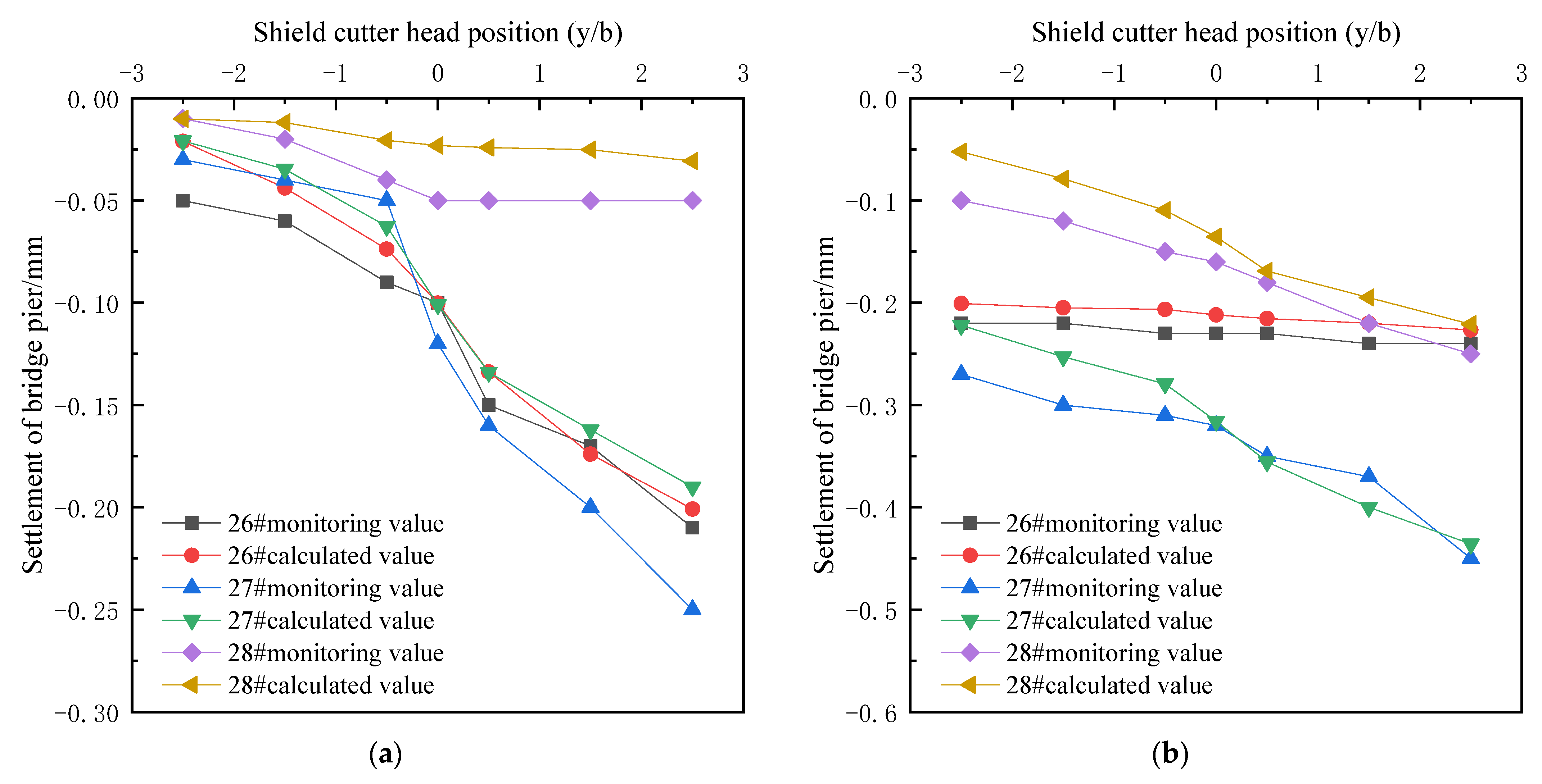
6. Verification of Numerical Simulation Results

The on-site monitoring of the entire construction process of the 13.67 m diameter shield tunneling through two 32 m simply supported box girders of the Shanghai-Nanjing high-speed railway was carried out in the north extension project of Tongjing Road in Suzhou. Two monitoring points were arranged on the top of each pier (as shown in Figure 1). In order to focus on the effects of shield tunneling near the pile foundations of the high-speed railway bridge on the displacements of pile foundations, the on-site monitoring data of piers displacements when the shield cutter head was just located at y/b = −2.5, −1.5, −0.5, 0, 0.5, 1.5 and 2.5 were selected, and the measured data of the first row of monitoring points were compared with the numerical simulation results (under the condition of isolation piles + MJS reinforcement + crown beams reinforcement), as shown in Figure 10. The numerical simulation results are basically consistent with the measured data, so the numerical simulation can better reflect the actual effects of shield tunneling on bridge pile foundations. During the whole construction process of shield tunneling, the settlement value of adjacent high-speed railway piers was controlled within ±1 mm, which meets the control requirements of ±2 mm settlement of piers of the existing high-speed railway under the condition of unlimited train speed. Therefore, the isolation piles + MJS reinforcement + crown beams reinforcement scheme actually adopted in the project has a good effect on the control of piers displacement, which can ensure the normal operation safety of high-speed rail trains during the shield tunneling construction.

7. Conclusions

In this paper, based on the actual project, the method of combining numerical simulation calculation and field measurement was used to explore the effects induced by large-diameter shield tunneling on the internal force and displacement of adjacent high-speed railway bridge pile foundations and the protective effect of different soil reinforcement schemes. The main research conclusions are as follows:
  • The completion of shield tunneling will cause additional bending moments of adjacent bridge piles. The bending moments’ distribution law of bridge piles in a symmetrical position is basically symmetrical. At the elevation above the tunnel crown or below the tunnel bottom, the bridge piles outside the twin tunnels mainly produce the bending moment which makes the side of the bridge piles away from the tunnel bear tension, and the maximum bending moment appears at the piles’ body at the same height as the center of the tunnels; the bending moment of bridge piles located between the twin tunnels is relatively small, which generally does not play a controlling role.
  • The completion of shield tunneling will cause additional lateral displacement of adjacent bridge piles. The lateral displacement distribution law of bridge piles in a symmetrical position is basically symmetrical. At the elevation above the tunnel crown or below the tunnel bottom, the bridge piles outside the twin tunnels mainly produce lateral displacement with direction pointing to the tunnel. At the elevation from the tunnel crown to the tunnel bottom, the bridge piles outside the twin tunnel mainly produce lateral displacement with direction away from the tunnel; the lateral displacement of bridge piles located between the twin tunnels is also relatively small, which generally does not play a control role.
  • The completion of shield tunneling will cause the settlement of adjacent pile foundations and piers. The settlement value of pile foundations and piers in symmetrical positions are almost the same. The settlement of the pier located between the twin tunnels is significantly higher than that of the piers outside the twin tunnels. Without any soil reinforcement measures, the final settlement of the pier located between the twin tunnels is −7.2 mm. Reinforcement measures must be adopted for the soil layer in the affected section in advance to meet the operation safety of high-speed railway trains during the construction of shield tunneling through the high-speed railway bridge.
  • The five soil layer reinforcement schemes can significantly reduce the bending moment and displacement of adjacent bridge pile foundations, and have better protection effects. The protection effect of isolated piles’ protection alone is better than that of MJS reinforcement alone, so isolated piles’ protection should be preferred. More than two kinds of soil reinforcement measures can be adopted at the same time to further control the lateral displacement and settlement of piers within ±1 mm, to ensure the absolute safety of high-speed rail trains’ operation during shield tunneling.
  • Under the condition of isolation piles + MJS reinforcement + crown beams reinforcement, the field monitoring of the displacements of adjacent piers during the construction of shield tunneling through the high-speed railway bridge was carried out. The numerical simulation results are basically consistent with the field monitoring data. Therefore, the numerical simulation can better reflect the actual effects of large-diameter shield tunneling on the pile foundation of adjacent high-speed railway bridges.

Author Contributions

Methodology, software, validation, and original draft preparation, Q.Y.; field monitoring data, funding acquisition, B.W.; conceptualization, supervision, review and editing, funding acquisition W.G. All authors have read and agreed to the published version of the manuscript.

Funding

This research was supported by Hunan Provincial Natural Science Foundation of China (Grant no. 2022JJ30720), Projects of China Railway Construction Corporation Limited (Grant no. 2021-C56), and China Railway Fifth Survey and Design Institute Group Corporation Limited (Grant no. T5Y2021-A03).

Institutional Review Board Statement

Not applicable.

Informed Consent Statement

Not applicable.

Data Availability Statement

Not applicable.

Conflicts of Interest

The authors declare no conflict of interest.

References

  1. Chen, L.; Poulos, H.G.; Loganathan, N.J.J.O.G. Pile responses caused by tunneling. J. Geotech. Geoenviron. Eng. 1999, 125, 207–215. [Google Scholar] [CrossRef]
  2. Jacobsz, S.W.; Standing, J.R.; Mair, R.J.; Hagiwara, T.; Sugiyama, T. Centrifuge modelling of tunnelling near driven piles. Soils Found. 2004, 44, 49–56. [Google Scholar] [CrossRef]
  3. Ng, C.W.W.; Lu, H.; Peng, S.Y. Three-dimensional centrifuge modelling of the effects of twin tunnelling on an existing pile. Tunn. Undergr. Space Technol. 2013, 35, 189–199. [Google Scholar] [CrossRef]
  4. Ng, C.W.W.; Soomro, M.A.; Hong, Y. Three-dimensional centrifuge modelling of pile group responses to side-by-side twin tunneling. Tunn. Undergr. Space Technol. 2014, 43, 350–361. [Google Scholar] [CrossRef]
  5. Basile, F. Effects of tunnelling on pile foundations. Soils Found. 2014, 54, 280–295. [Google Scholar] [CrossRef]
  6. Yoo, C. Interaction between tunneling and bridge foundation–A 3D numerical investigation. Comput. Geotech. 2013, 49, 70–78. [Google Scholar] [CrossRef]
  7. Li, Z.; Chen, Z.; Wang, L.; Zeng, Z.; Gu, D. Numerical simulation and analysis of the pile underpinning technology used in shield tunnel crossings on bridge pile foundations. Undergr. Space. 2021, 6, 396–408. [Google Scholar] [CrossRef]
  8. Yang, M.; Sun, Q.; Li, W.C.; Ma, K. Three-dimensional finite element analysis on effects of tunnel construction on nearby pile foundation. J. Cent. South Univ. 2011, 18, 909–916. [Google Scholar] [CrossRef]
  9. Ng, C.W.W.; Lu, H. Effects of the construction sequence of twin tunnels at different depths on an existing pile. Can. Geotech. J. 2014, 51, 173–183. [Google Scholar] [CrossRef]
  10. Soomro, M.A.; Ng, C.W.W.; Memon, N.A.; Bhanbhro, R. Lateral behaviour of a pile group due to side-by-side twin tunnelling in dry sand: 3D centrifuge tests and numerical modelling. Comput. Geotech. 2018, 101, 48–64. [Google Scholar] [CrossRef]
  11. He, S.; Lai, J.; Li, Y.; Wang, K.; Wang, L.; Zhang, W. Pile group response induced by adjacent shield tunnelling in clay: Scale model test and numerical simulation. Tunn. Undergr. Space Technol. 2022, 120, 104039. [Google Scholar] [CrossRef]
  12. Pang, C.H.; Yong, K.Y.; Chow, Y.K. Three-dimensional numerical simulation of tunnel advancement on adjacent pile foundation. Undergr. Space Use Anal. Past Lessons Future. 2005, 2, 1141–1148. [Google Scholar]
  13. Liu, C.; Zhang, Z.; Regueiro, R.A. Pile and pile group response to tunnelling using a large diameter slurry shield—Case study in Shanghai. Comput. Geotech. 2014, 59, 21–43. [Google Scholar] [CrossRef]
  14. Shen, J.W.; Liu, L. Numerical analysis and field monitoring for studying effects of shield tunnelling on nearby piles. Rock Soil Mech 2015, 36, 709–714. (In Chinese) [Google Scholar]
  15. Li, C.; Zhong, Z.; He, G.; Liu, X. Response of the ground and adjacent end-bearing piles due to side-by-side twin tunnelling in compound rock strata. Tunn. Undergr. Space Technol. 2019, 89, 91–108. [Google Scholar] [CrossRef]
  16. Wang, J.; Wen, Z. Analysis of Construction Impact of a Large Diameter Shield Tunneling Side-Crossing Viaduct Pile Foundations in Short Distance. Geotech. Geol. Eng. 2021, 39, 5587–5598. [Google Scholar] [CrossRef]
  17. Liu, Z.; He, P.; Zhang, A.Q. Analysis of Effects of Shield Tunnel Construction Process and Supporting Ways on Pile Groups of High-speed Railway Viaduct. Eng. Mech. 2016, 33, 219–226. (In Chinese) [Google Scholar]
  18. Tang, J.; Yan Liu, J.; Liu, Y. Study on the measures of tunnels side-crossing bridge based on sheltering effects of isolation piles. In Proceedings of the IOP Conference Series: Earth and Environmental Science, Zhuhai, China, 28’30 April 2017; Volume 81, p. 012156. [Google Scholar]
  19. Ma, W.; Liu, J.; Zhang, L. Analysis of the impact of large-diameter shield construction adjacent to the side of the pile foundation. In Proceedings of the IOP Conference Series: Earth and Environmental Science, Changsha, China, 18’20 September 2020; Volume 634, p. 012109. [Google Scholar]
  20. Wu, B.; Zhang, Z.; Huang, W. Comparison and selection of reinforcement schemes for shield tunnelling close crossing high-speed railway viaduct group. In Proceedings of the IOP Conference Series: Earth and Environmental Science, Guangzhou, China, 08’10 March 2019; Volume 267, p. 042119. [Google Scholar]
  21. Wang, K.; Li, Z.P.; Jiang, H.T. The Deformation Laws and Control Measures of the Bridge Affected by the Construction of Long-Distance Overlapping Tunnels. Chin. Civil. Eng. J. 2020, 53, 180–185. (In Chinese) [Google Scholar]
  22. Qiu, H.; Wang, Z.; Ayasrah, M.M.; Fu, C.; Gang, L. Numerical Study on the Reinforcement Measures of Tunneling on Adjacent Piles. Symmetry 2022, 14, 288. [Google Scholar] [CrossRef]
  23. Li, X.X.; Yang, Z.H. Influences of Construction of Side-crossing Shield Tunnel on Adjacent Pile Foundation and Reinforcement Effect of Protection Measures. Rock Soil Mech. 2015, 36, 537–541. (In Chinese) [Google Scholar]
  24. Li, Z.; Lv, J.; Xie, X.; Fu, H.; Huang, J.; Li, Z. Mechanical Characteristics of Structures and Ground Deformation Caused by Shield Tunneling Under-Passing Highways in Complex Geological Conditions Based on the MJS Method. Appl. Sci. 2021, 11, 9323. [Google Scholar] [CrossRef]
  25. Li, C.; Gong, B.; Tao, H.; Chen, Y. Numerical Investigation of Deformation Influence of Existing Viaduct Piles under MJS Construction Method. J. Eng. Sci. Tech. Rev. 2022, 15, 32–39. [Google Scholar] [CrossRef]
  26. Li, X.; Zhang, D.; Hou, Y.; Cao, L.; Li, Q. Analysis of Ground and Structure Deformation Characteristics During Shield Tunneling in Tianjin Subway. China Railw. Sci 2018, 39, 71–80. (In Chinese) [Google Scholar]
  27. Lou, P.; Li, Y.; Lu, S.; Xiao, H.; Zhang, Z. Deformation and Mechanical Characteristics of Existing Foundation Pit and Tunnel Itself Caused by Shield Tunnel Undercrossing. Symmetry 2022, 14, 263. [Google Scholar] [CrossRef]
  28. Drucker, D.C.; Prager, W. Soil mechanics, and plastic analysis or limit design. Q. Appl. Math. 1952, 10, 157–165. [Google Scholar] [CrossRef] [Green Version]
  29. Alejano, L.R.; Bobet, A. Drucker—prager criterion. In The ISRM Suggested Methods for Rock Characterization, Testing and Monitoring: 2007-2014. Springer: Cham, Switzerland, 2012; pp. 247–252. [Google Scholar]
  30. Zhou, S.; Wang, B.; Dong, X.; Sun, Y. Computational and Analytical Methods in Urban Rail Transit Underground Engineering, 1st ed.; China Communications Press: Beijing, China, 2014; pp. 109–110. [Google Scholar]
  31. Zhu, F.; Yang, P.; Ong, C.W. Numerical Analysis on Influence of Shield Tunnel Excavation to Neighboring Piles. Chin. J. Geotech. Eng. 2008, 2, 298–302. (In Chinese) [Google Scholar]
  32. TB 10182-2017; National Railway Administration of the People’s Republic of China. Technical Specification for Highway and Municipal Engineering under Crossing High Speed Railway. China Railway Publishing House: Beijing, China, 2017.
Figure 1. Schematic diagram of soil reinforcement range. (a) Front view; (b) vertical view.
Symmetry 14 01913 g001
Figure 2. Three-dimensional finite element model. (a) Overall perspective; (b) partial perspective.
Symmetry 14 01913 g002
Figure 3. The schematic diagram of the shield tunneling process.
Symmetry 14 01913 g003
Figure 4. Bending moment of bridge piles under each cap without soil reinforcement measures. (a) Under 26# cap; (b) under 27# cap; (c) under 28# cap.
Symmetry 14 01913 g004
Figure 5. Lateral displacement of bridge piles under each cap without soil reinforcement measures. (a) Under 26# cap; (b) under 27# cap; (c) under 28# cap.
Symmetry 14 01913 g005aSymmetry 14 01913 g005b
Figure 6. Displacement cloud diagram of the numerical model without soil reinforcement measures (unit: m). (a) Vertical; (b) lateral.
Symmetry 14 01913 g006
Figure 7. Cloud diagram of pile foundations settlement without soil reinforcement measures (unit: m).
Symmetry 14 01913 g007
Figure 8. Bending moment diagram of typical bridge piles under different conditions. (a) 26#c2 pile; (b) 28#a2 pile.
Symmetry 14 01913 g008
Figure 9. Lateral displacement diagram of typical bridge piles under different conditions. (a) 26#c2 pile; (b) 28#a2 pile.
Symmetry 14 01913 g009
Figure 10. Comparison of cumulative monitored settlement and numerical calculation values of piers monitoring points. (a) Shield tunneling of the left line; (b) shield tunneling of the right line.
Symmetry 14 01913 g010
Table 1. Physical and mechanical parameters of undisturbed soil and MJS reinforcement.
Soil LayersThick
(m)
Density
(kN·m−3)
Cohesion Force
(kPa)
Frictional
Angle (°)
Compression
Modulus (MPa)
Poisson’s Ratio
Artificial fill518.210154.50.3
Silty clay 11019181250.3
Silt2218.9222270.27
Clay1619.2351480.3
Silty clay 22719.430146.50.25
MJS reinforcement2140234000.23
Table 2. Physical and mechanical parameters of structures.
StructuresDensity (kN·m−3)Elastic Modulus (MPa)Poisson’s Ratio
Shield shell142210,0000.3
Segment2634,5000.2
Isochronous layer22.550 (early stage)0.25
500 (later stage)
Bridge piers2531,5000.2
Pile foundations2531,5000.2
Isolation piles2530,0000.2
Crown beams2530,0000.2
Table 3. Maximum bending moment of typical bridge piles and displacement of piers top under different conditions.
ConditionMaximum Bending Moment of Bridge Piles (kN•m)Lateral Displacement of
Piers Top (mm)
Settlement of Piers Top (mm)
26#c228#a226#c228#a226#27#28#
Unreinforced−2452487.1−6.5−4.7−7.2−4.6
Piles−59621.2−1.1−0.4−1.2−0.3
MJS−1111091.5−1.4−1.2−1.8−1.2
Piles + beams−43380.9−0.8−0.2−1.0−0.2
Piles + MJS−57560.6−0.6−0.4−0.6−0.4
Piles + MJS + beams−50480.3−0.2−0.2−0.4−0.2
Publisher’s Note: MDPI stays neutral with regard to jurisdictional claims in published maps and institutional affiliations.

