
Study on Transverse Deformation Characteristics of a Shield Tunnel under Earth Pressure by Refined Finite Element Analyses

Abstract
:1. Introduction
2. Numerical Model Construction and Validation
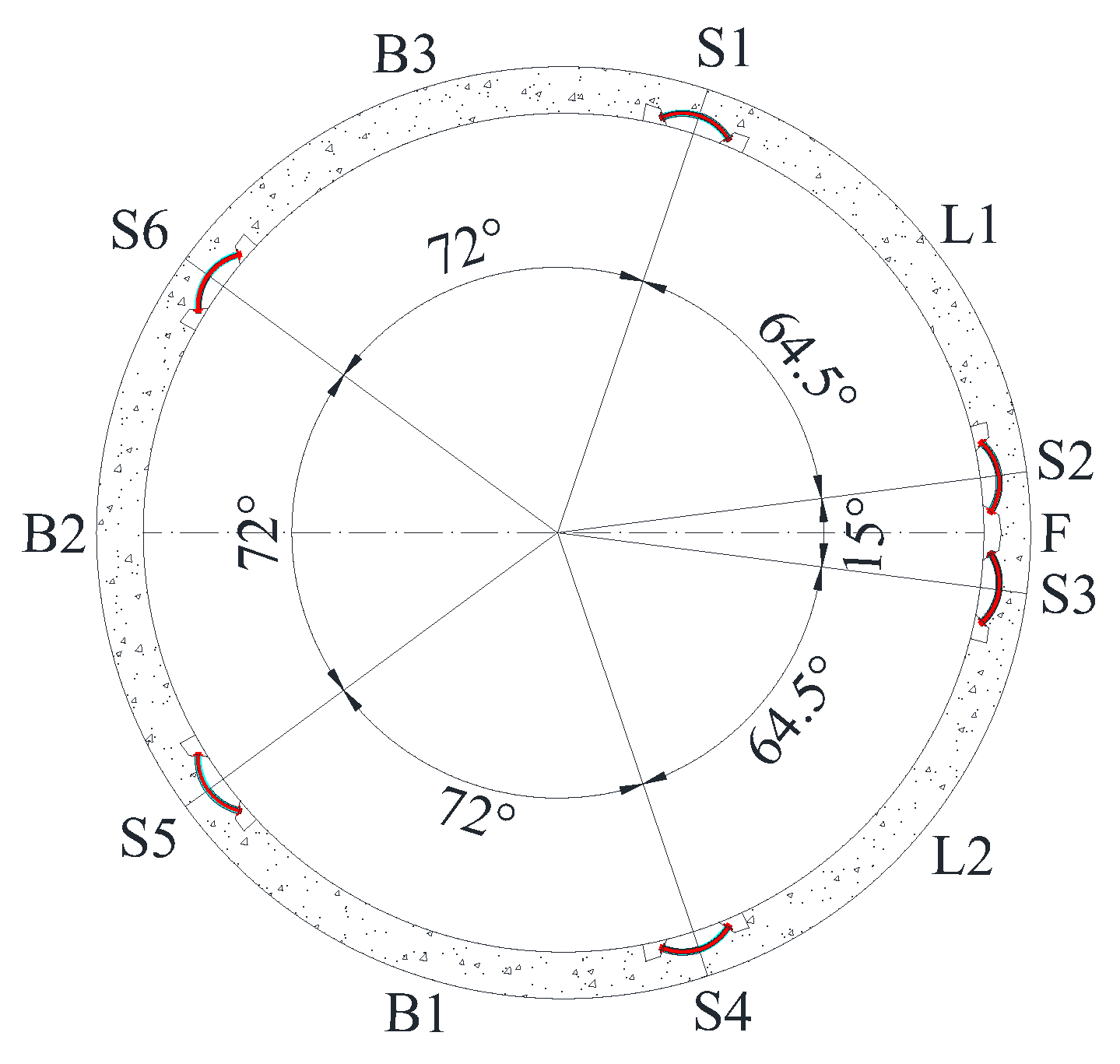
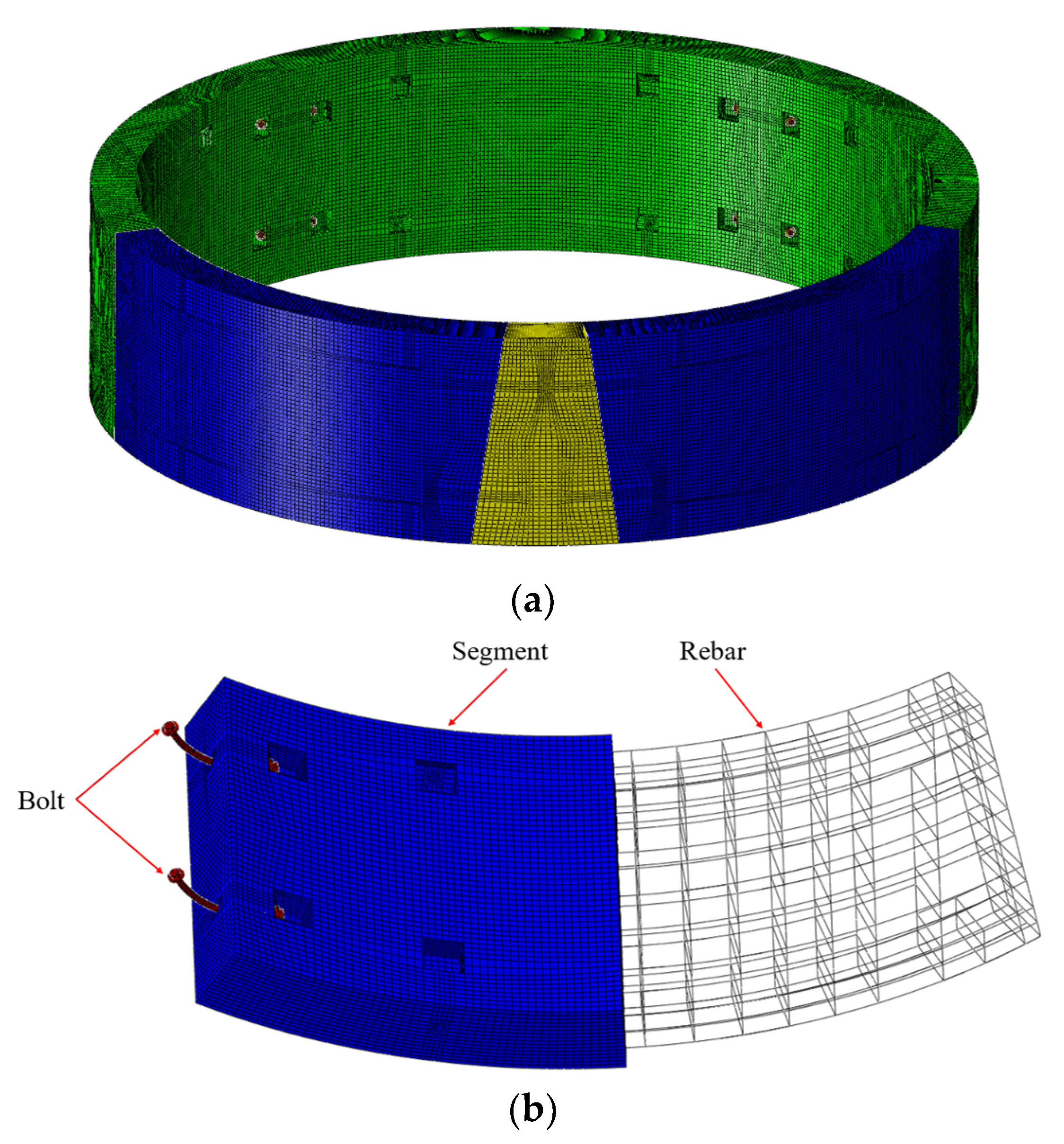
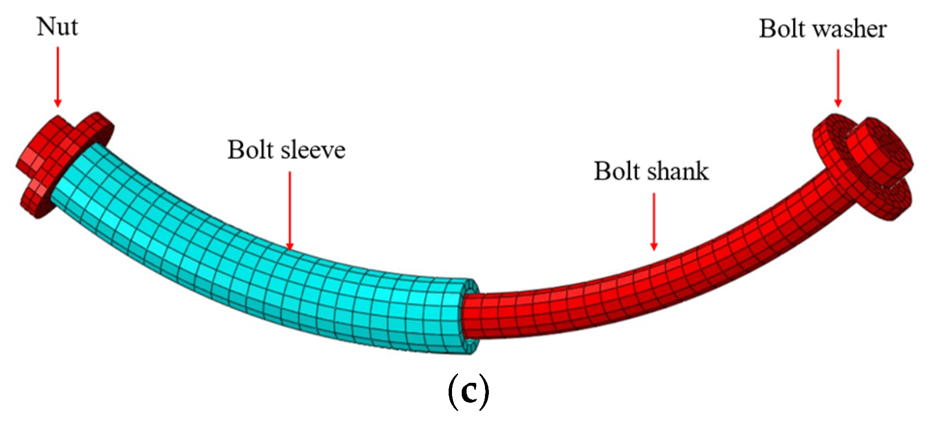
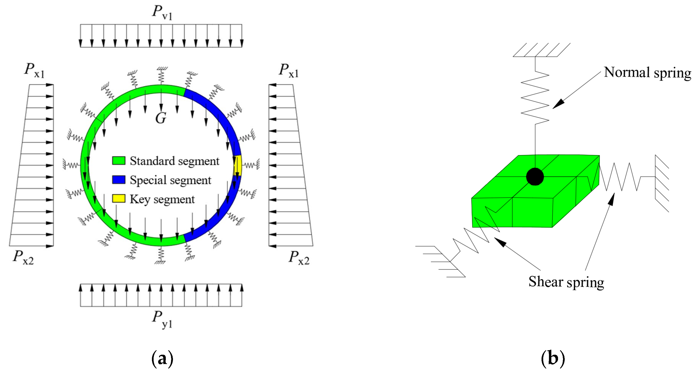
2.1. Finite Element Model
2.2. Constitutive Model and Parameters
2.3. Interactions
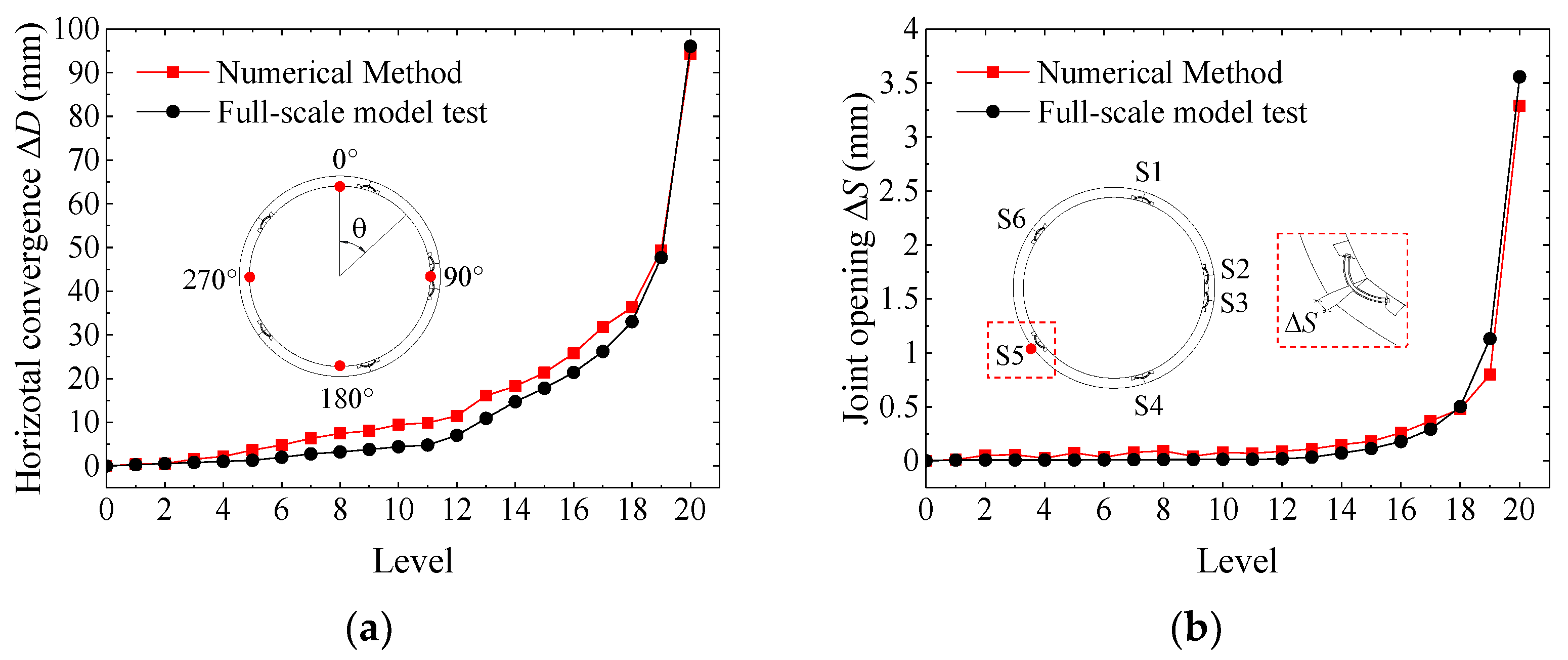
2.4. Validation
3. Loading Mode and Numerical Cases
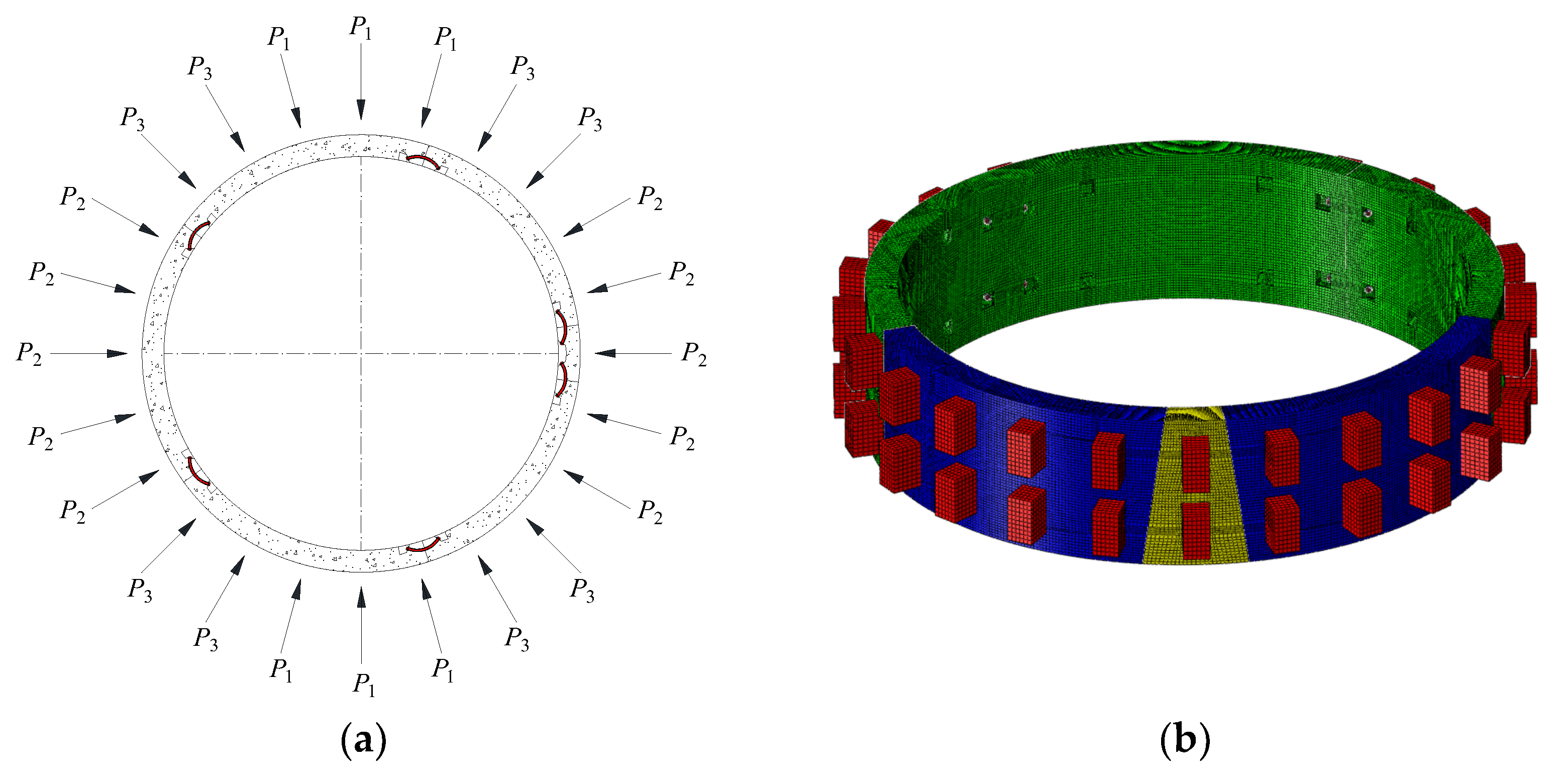
3.1. Loading Mode
3.2. Numerical Cases
4. Results and Analyses
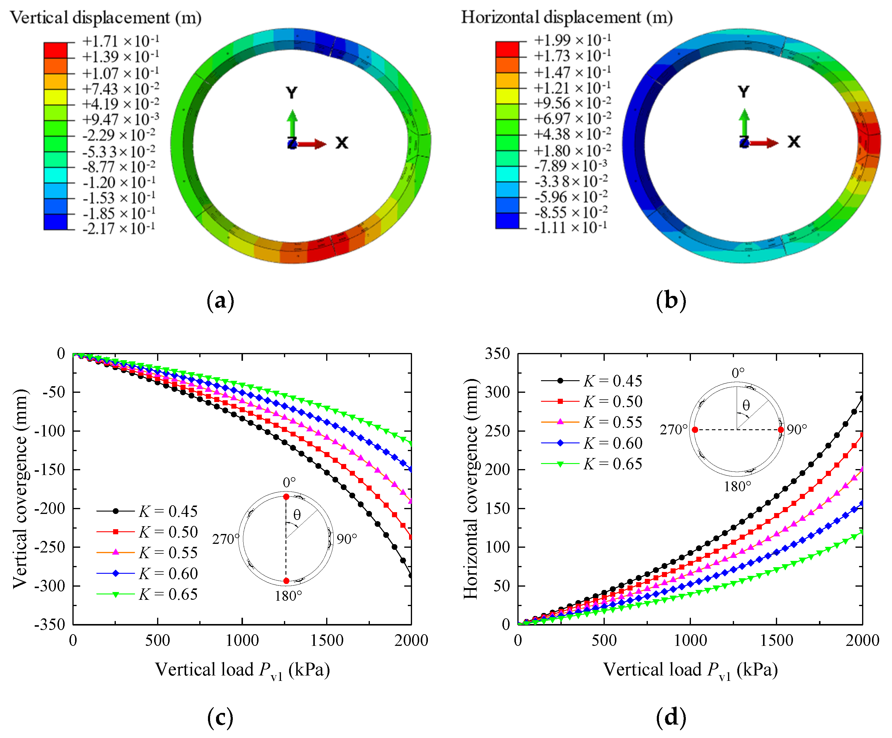
4.1. Convergence
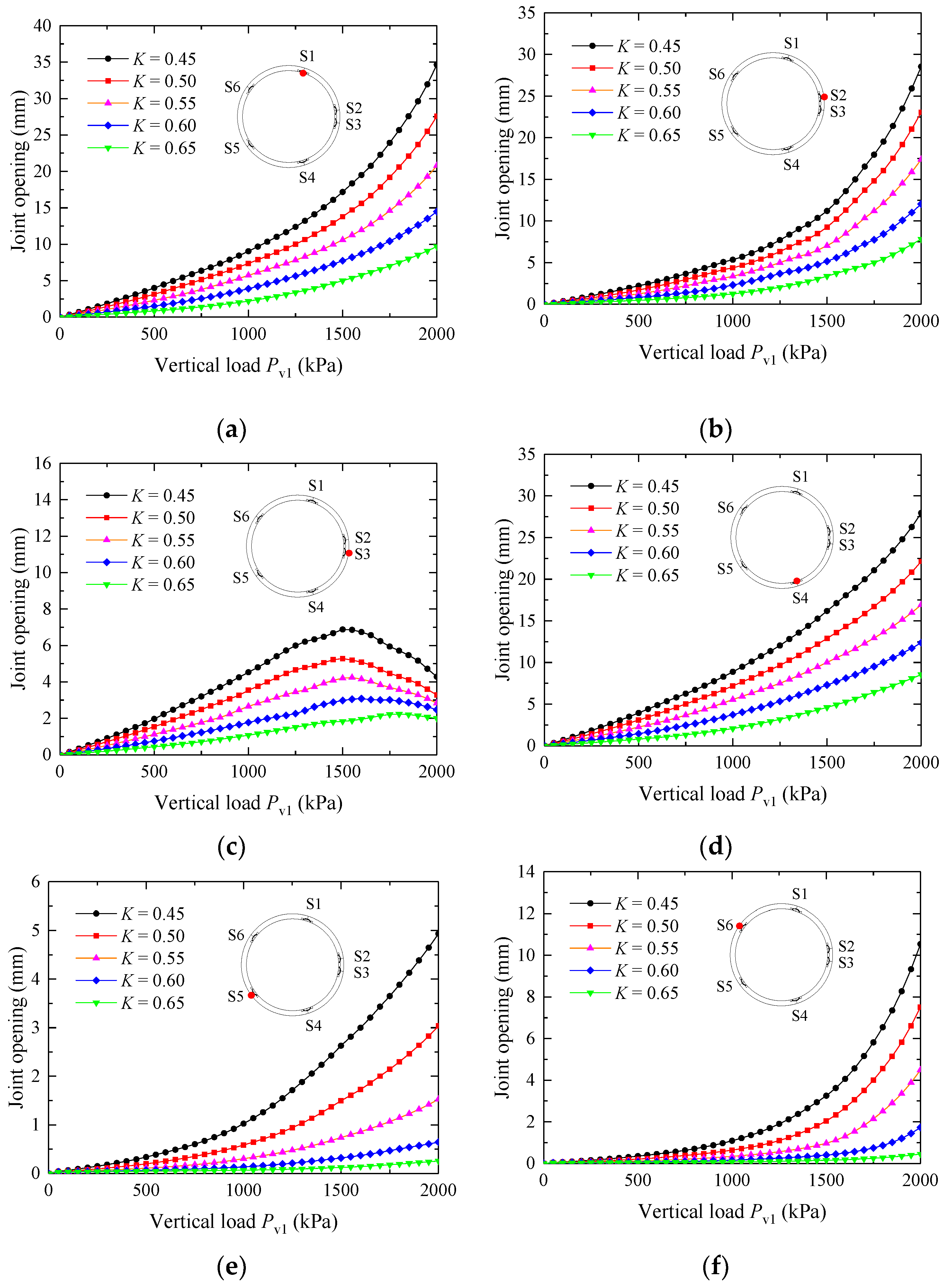
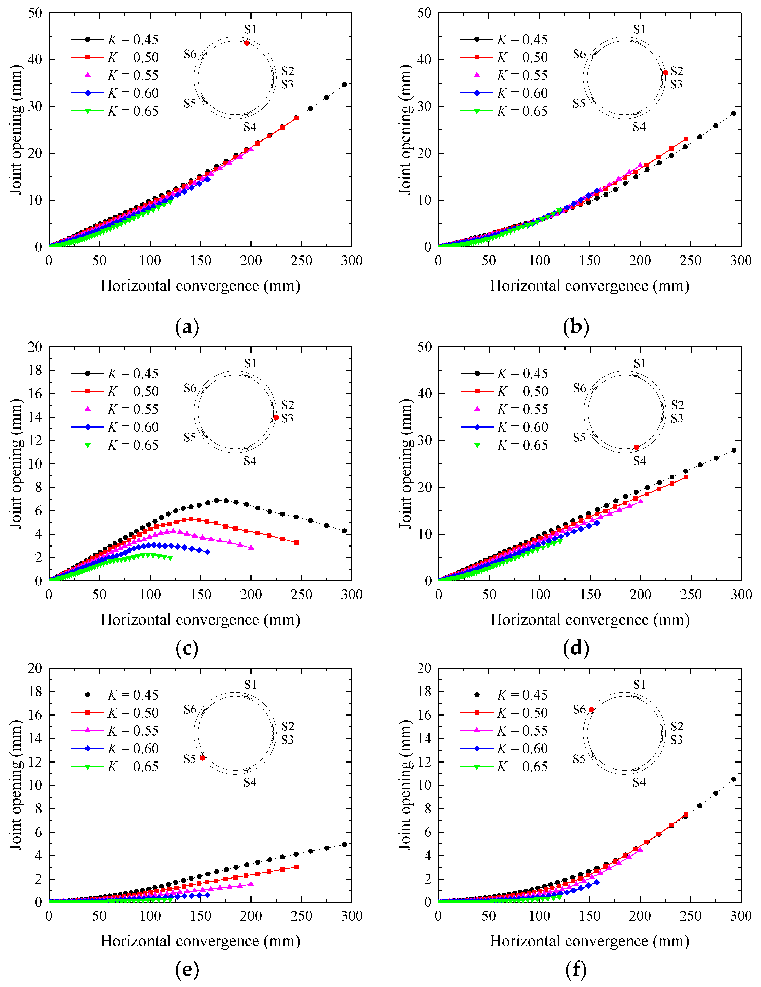
4.2. Joint Deformation
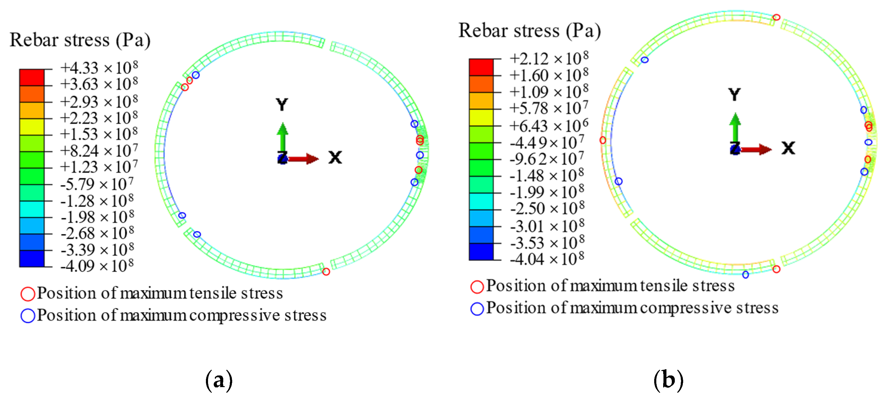
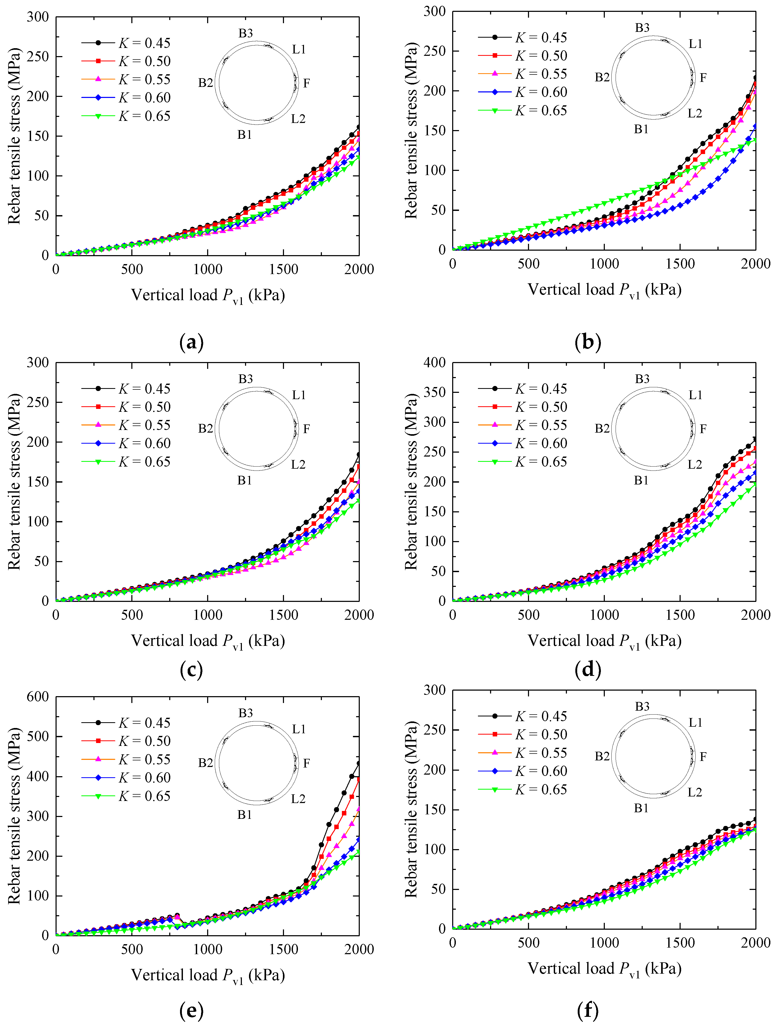
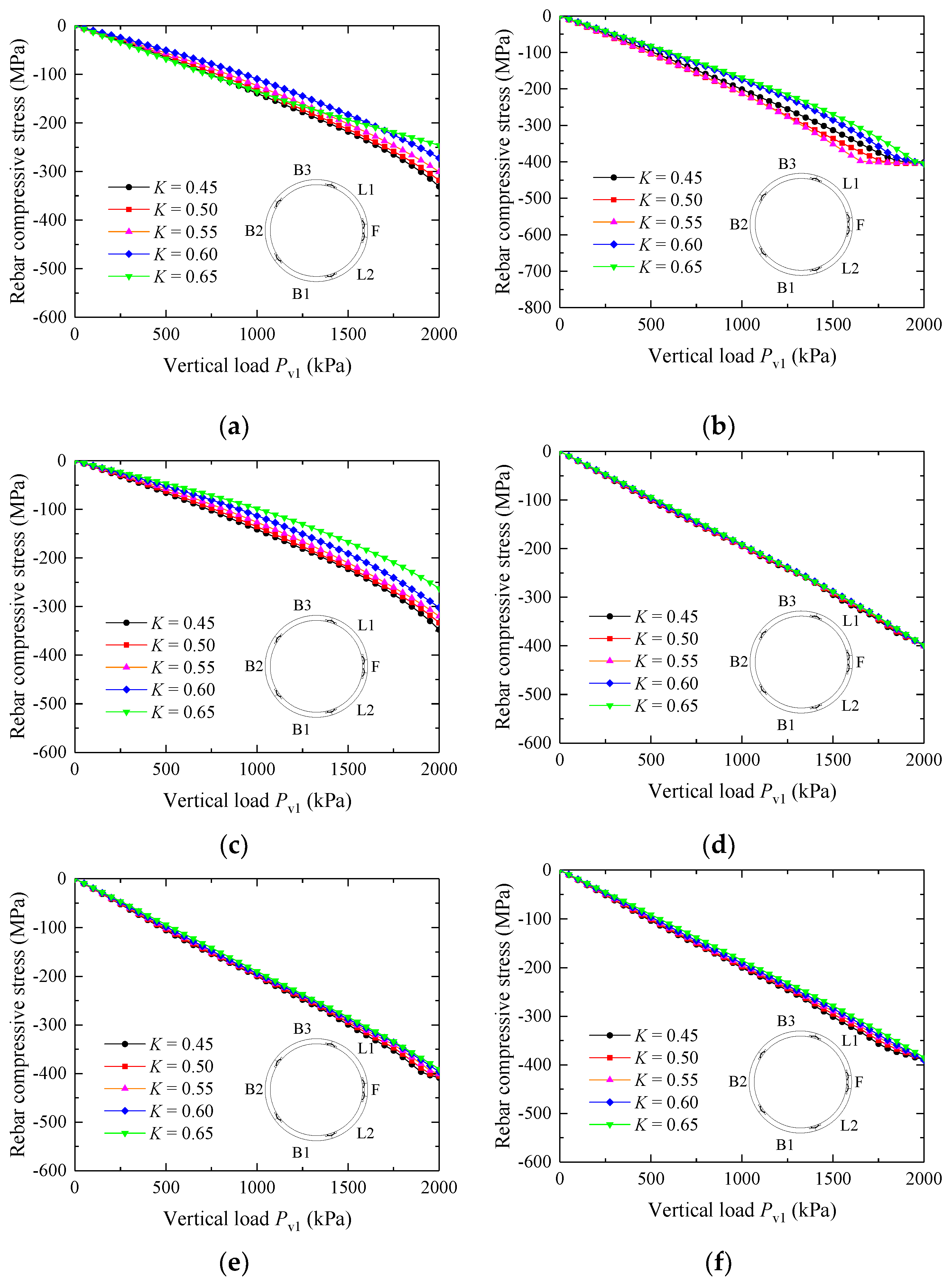
4.3. Rebar Stress
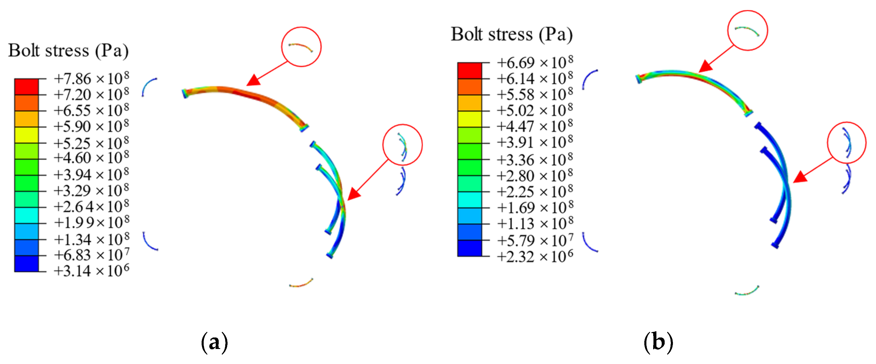
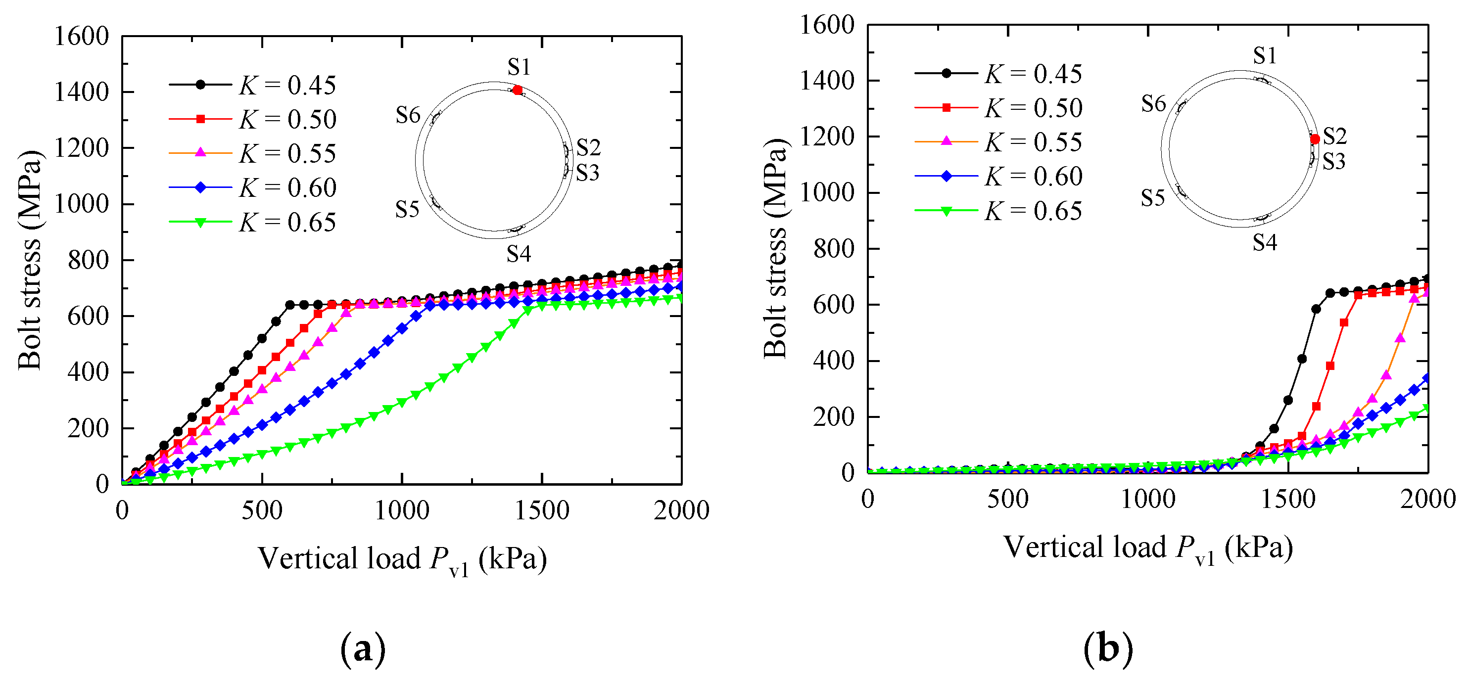
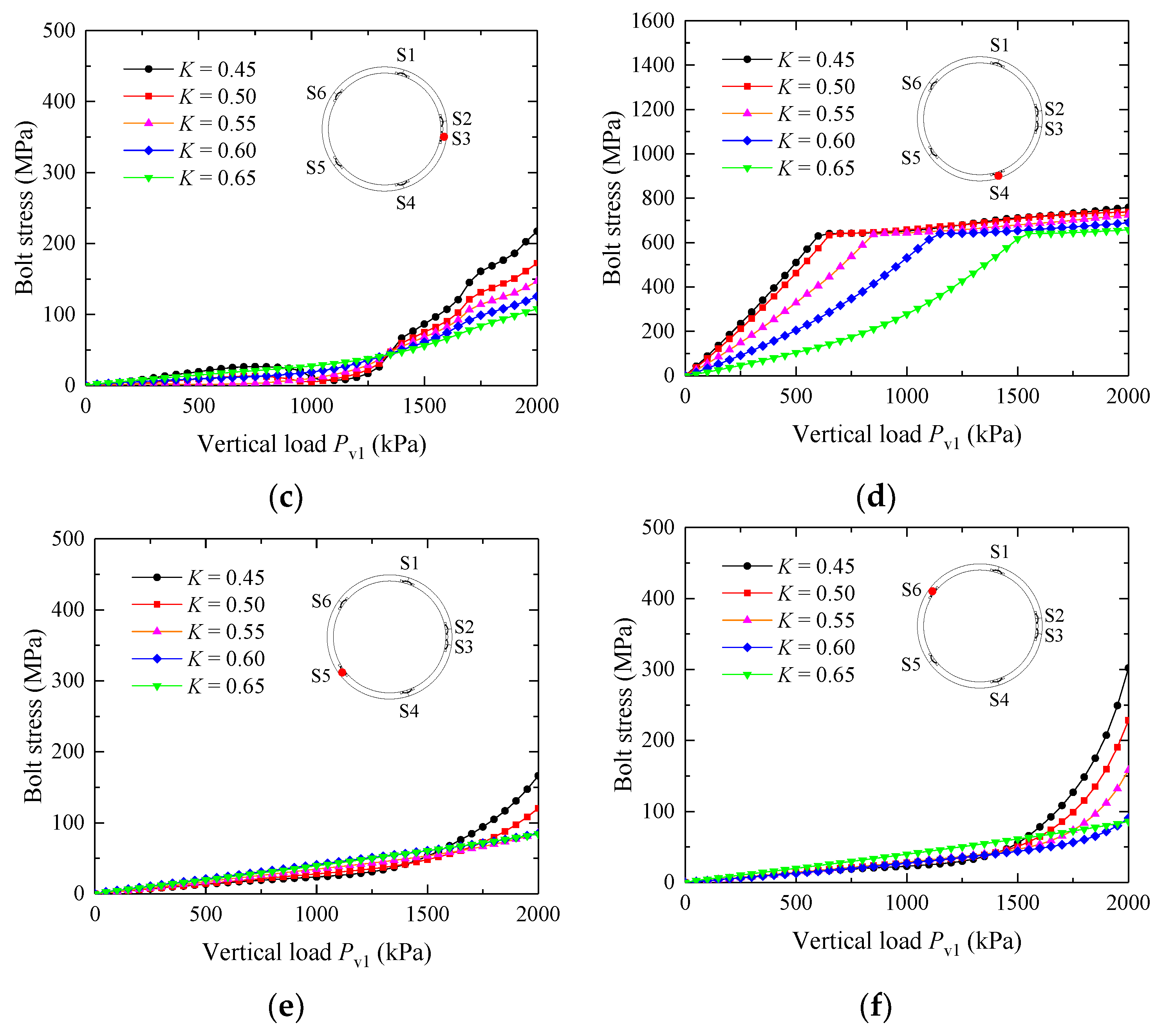
4.4. Bolt Stress
5. Discussions
5.1. Relationship between Convergence and Joint Opening
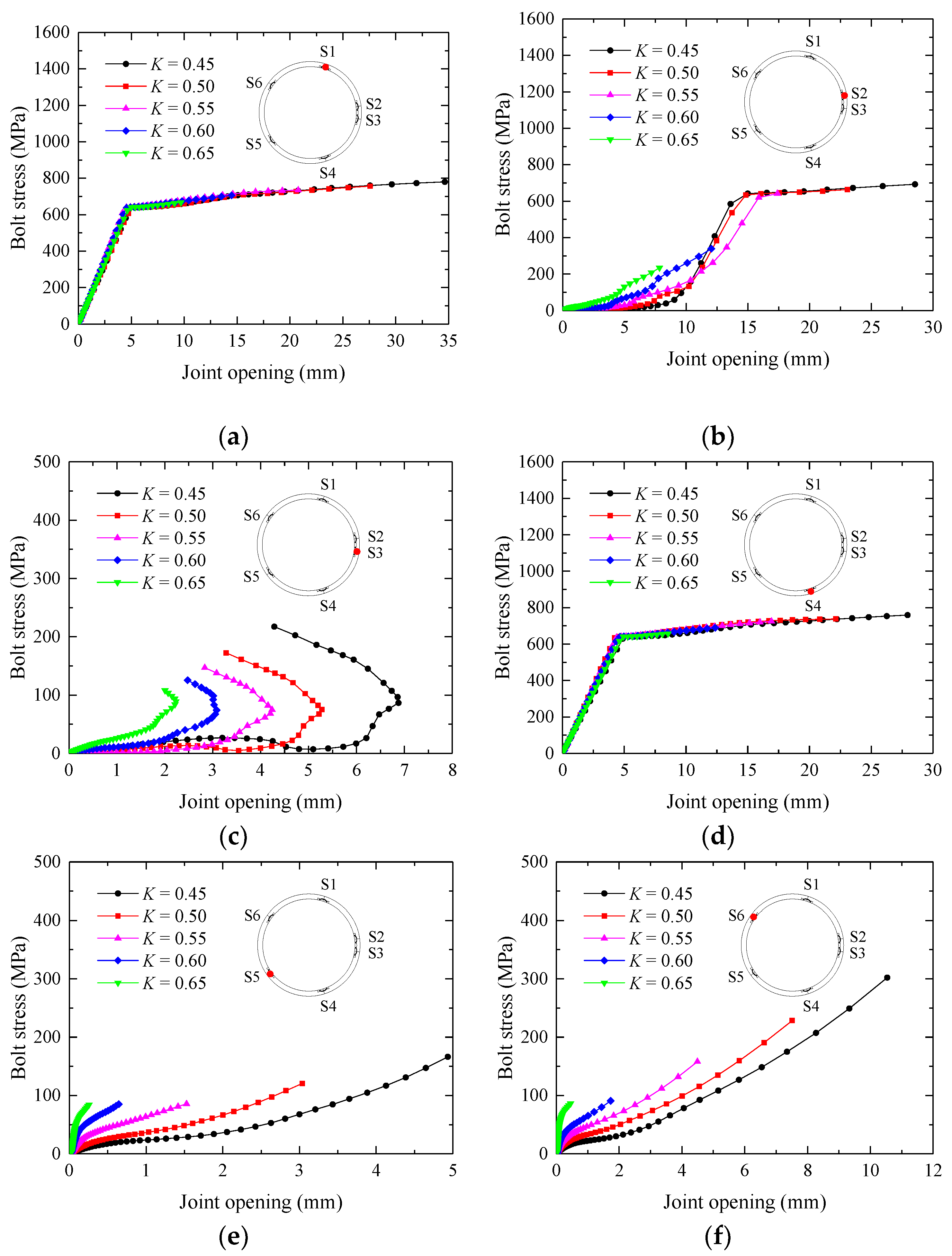
5.2. Relationship between Joint Opening and Bolt Stress
6. Conclusions
- (1)
- In this study, we have established a refined numerical model for the segmental lining of a shield tunnel using finite element software, which contains detailed models of the reinforcement and connecting bolts. The model parameters were validated using a full-scale model test result. The numerical calculation results highly agree with the full-scale test, which verifies the accuracy of the numerical model. We prove that the refined numerical simulation method reasonably reflects the deformation of the segmental lining and can be used in subsequent studies.
- (2)
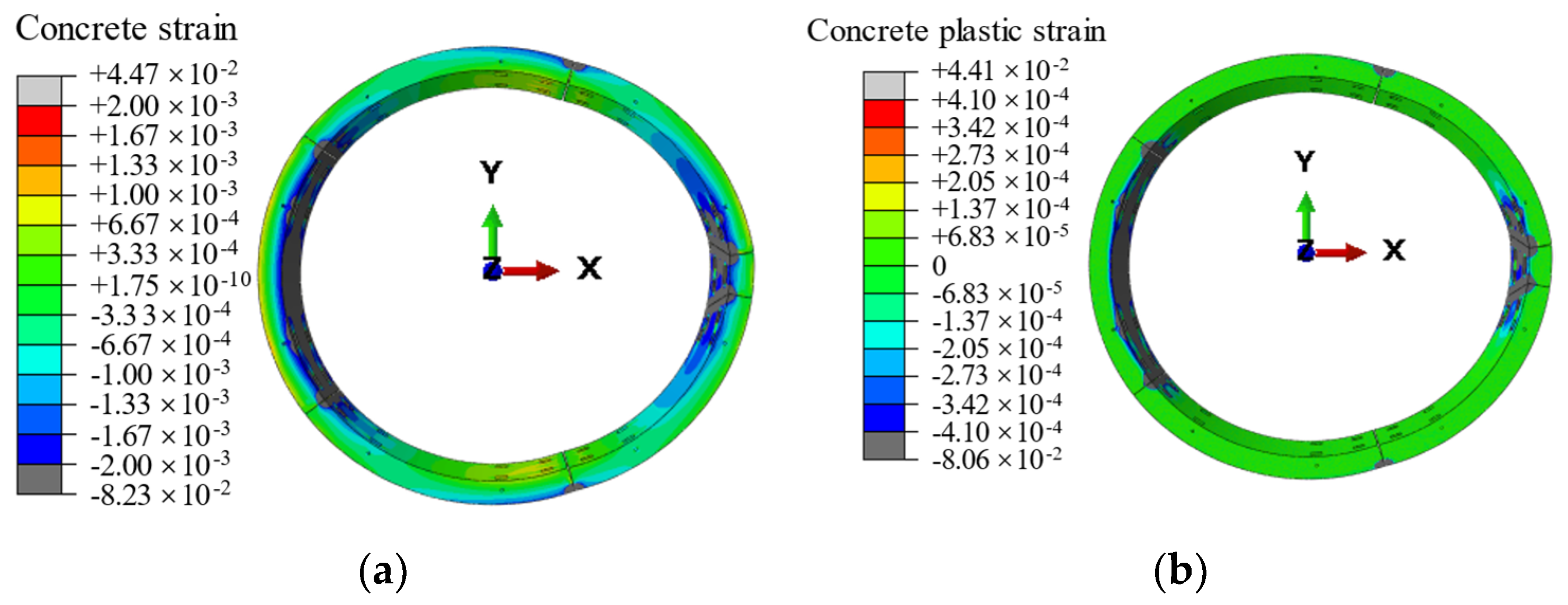
- When the lining is deformed by earth pressure, the concrete at the joints is squeezed to produce large strains, resulting in plastic hinges forming at the joints. When the lining is deformed by earth pressure, the segment rotates around the plastic hinge, causing the joints to open. The rotation of the segment is the main reason for segmental lining deformation under earth pressure.
- (3)
- Horizontal convergence is a single index reflecting the deformation of the tunnel ring, representing the overall deformation of the ring to a certain extent but not the deformation characteristics of the joint. When loading conditions differ, the relationship between joint opening and horizontal convergence is consistent for some joints and inconsistent for others.
- (4)
- When the joint is open in the outer arc, the relationship between joint opening and bolt stress is different under different loading conditions. However, the relationship between joint opening and bolt stress is consistent when opening in the inner arc; bolt stress reaches a yield of 640 MPa, with a joint opening range of 4.50–5.50 mm.
Author Contributions
Funding
Institutional Review Board Statement
Informed Consent Statement
Data Availability Statement
Conflicts of Interest
References
- Shen, S.L.; Cui, Q.L.; Ho, E.C.; Xu, Y.S. Ground response to multiple parallel Micro tunneling operations in cemented silty clay and sand. J. Geotech. Geoenviron. Eng. 2016, 142, 04016001. [Google Scholar] [CrossRef]
- Wu, H.N.; Shen, S.L.; Yang, J.; Zhou, A.N. Soil-tunnel interaction modeling for shield tunnels considering shearing dislocation in longitudinal joints. Tunn. Undergr. Space Technol. 2018, 78, 168–177. [Google Scholar] [CrossRef]
- Lei, M.F.; Peng, L.M.; Shi, C.H. An experimental study on durability of shield segments under load and chloride environment coupling effect. Tunn. Undergr. Space Technol. 2014, 42, 15–24. [Google Scholar] [CrossRef]
- Wood, A. The circular tunnel in elastic ground. Géotechnique 1975, 25, 115–127. [Google Scholar] [CrossRef]
- Lee, K.M.; Ge, X.W. The equivalence of a jointed shield-driven tunnel lining to a continuous ring structure. Can. Geotech. J. 2001, 38, 461–483. [Google Scholar] [CrossRef]
- Liao, S.M.; Peng, F.L.; Shen, S.L. Analysis of shearing effect on tunnel induced by load transfer along longitudinal direction. Tunn. Undergr. Space Technol. 2008, 23, 421–430. [Google Scholar] [CrossRef]
- Huang, X.; Huang, H.W.; Zhang, J. Flattening of jointed shield-driven tunnel induced by longitudinal differential settlements. Tunn. Undergr. Space Technol. 2012, 31, 20–32. [Google Scholar] [CrossRef]
- Koyama, Y. Present status and technology of shield tunneling method in Japan. Tunn. Undergr. Space Technol. 2003, 18, 145–149. [Google Scholar] [CrossRef]
- Huang, W.M.; Wang, J.C.; Yang, Z.X.; Xu, R.Q. Analytical model for segmental tunnel lining with nonlinear joints. Tunn. Undergr. Space Technol. 2021, 114, 103994. [Google Scholar] [CrossRef]
- Huang, Z.R.; Zhu, W.; Liang, J.H.; Lin, J.; Jia, R. Three-dimensional numerical modelling of shield tunnel lining. Tunn. Undergr. Space Technol. 2006, 21, 434. [Google Scholar] [CrossRef]
- Arnau, O.; Molins, C. Three dimensional structural response of segmental tunnel linings. Eng. Struct. 2012, 44, 210–221. [Google Scholar] [CrossRef]
- Blom, C.; Van, D.; Jovanovic, P.S. Three-dimensional structural analyses of the shield-driven “Green Heart” tunnel of the high-speed line South. Tunn. Undergr. Space Technol. 1999, 14, 217–224. [Google Scholar] [CrossRef]
- Schreyer, J.; Winselmann, D. Suitability tests for the lining of the 4th Elbe tunnel tube–results of large-scale tests. Tunnel 2000, 1, 34–44. [Google Scholar]
- Vervuurt, A.; Luttikholt, A. Failure behavior of segmented tunnel linings: Numerical modeling validated by full scale tests. In Proceedings of the Eccomas Thematic Conference on Computational Methods in Tunneling, Vienna, Austria, 27–29 August 2007; pp. 1–13. [Google Scholar]
- Liu, X.; Dong, Z.; Bai, Y.; Zhu, Y.H. Investigation of the structural effect induced by stagger joints in segmental tunnel linings: First results from full-scale ring tests. Tunn. Undergr. Space Technol. 2017, 66, 1–18. [Google Scholar] [CrossRef]
- Liu, X.; Ye, Y.; Liu, Z.; Liu, Z.; Huang, D.Z. Mechanical behavior of Quasi-rectangular segmental tunnel linings: First results from full-scale ring tests. Tunn. Undergr. Space Technol. 2018, 71, 440–453. [Google Scholar] [CrossRef]
- Molins, C.; & Arnau, O. Experimental and analytical study of the structural response of segmental tunnel linings based on an in situ loading test. Part 1: Test configuration and execution. Tunn. Undergr. Space Technol. 2011, 26, 764–777. [Google Scholar] [CrossRef]
- Lu, Y. Full-scale Model Test of Shield Tunnel Segment and Simulation Analysis of Circumferential Joint; China Academy of Railway Sciences: Beijing, China, 2019. (In Chinese) [Google Scholar]
- Yamamoto, K.; Lyamin, A.V.; Wilson, D.W.; Sloan, S.W.; Abbo, A.J. Stability of a circular tunnel in cohesive-frictional soil subjected to surcharge loading. Comput. Geotech. 2011, 38, 504–514. [Google Scholar] [CrossRef]
- Liu, J.W.; Shi, C.H.; Lei, M.F.; Wang, Z.X.; Cao, C.Y. A study on damage mechanism modelling of shield tunnel under unloading based on damage–plasticity model of concrete. Eng. Fail. Anal. 2021, 123, 105261. [Google Scholar] [CrossRef]
- Shi, C.H.; Cao, C.Y.; Lei, M.F.; Peng, L.M.; Ai, H.J. Effects of lateral unloading on the mechanical and deformation performance of shield tunnel segment joints. Tunn. Undergr. Space Technol. 2016, 51, 175–188. [Google Scholar] [CrossRef]
- Jiang, L.; Hao, S.Y. Resilience Evaluation of the Existing Shield Tunnel Lining Induced by the Symmetrical Excavation of Adjacent Foundation Pit Based on Numerical Simulations. Symmetry 2022, 14, 229. [Google Scholar] [CrossRef]
- Lou, P.; Li, Y.H.; Lu, S.D.; Xiao, H.B.; Zhang, Z.G. Deformation and Mechanical Characteristics of Existing Foundation Pit and Tunnel Itself Caused by Shield Tunnel Undercrossing. Symmetry 2022, 14, 263. [Google Scholar] [CrossRef]
- Chakeri, H.; Hasanpour, R.; Hindistan, M.A.; Ünver, B. Analysis of interaction between tunnels in soft ground by 3D numerical modeling. Bull. Eng. Geol. Environ. 2011, 70, 439–448. [Google Scholar] [CrossRef]
- GB50010; Code for Design of Concrete Structures. China Architecture and Building Press: Beijing, China, 2010. (In Chinese)
- ABAQUS. Abaqus User’s Manual, Version 2021; Hibbit, Karlsson & Sorenson, Inc.: Pawtucket, RI, USA, 2021. [Google Scholar]
- Mashimo, H.; Ishimura, T. Evaluation of the load on shield tunnel lining in gravel. Tunn. Undergr. Space Technol. 2003, 18, 233–241. [Google Scholar] [CrossRef]
- Wang, F.; Zhang, D.M.; Zhu, H.H.; Huang, H.W.; Yin, J.H. Impact of overhead excavation on an existing shield tunnel: Field monitoring and a full 3D finite element analysis. CMC—Comput. Mater. Con. 2013, 34, 63–81. [Google Scholar]


| Material | E (MPa) | ν | σ0 (MPa) | σu (MPa) |
|---|---|---|---|---|
| Segmental lining | 34,500 | 0.2 | 46 | 55 |
| Rebar | 200,000 | 0.3 | 400 | 500 |
| Bolt | 206,000 | 0.3 | 640 | 800 |
| Bolt washer | 206,000 | 0.3 | — | — |
| Bolt sleeve | 2000 | 0.35 | — | — |
| Level | P1 (kN) | P2 (kN) | P3 (kN) | Level | P1 (kN) | P2 (kN) | P3 (kN) |
|---|---|---|---|---|---|---|---|
| 0 | 0 | 0 | 0 | 11 | 278 | 210 | 205 |
| 1 | 31 | 26.4 | 26.2 | 12 | 309.2 | 228 | 231 |
| 2 | 62 | 52.8 | 52.4 | 13 | 340.4 | 246 | 257 |
| 3 | 93 | 79.2 | 78.6 | 14 | 356 | 255 | 270 |
| 4 | 124 | 105.6 | 104.8 | 15 | 381.4 | 272.2 | 287.6 |
| 5 | 155 | 132 | 131 | 16 | 406.8 | 289.4 | 305 |
| 6 | 187 | 152.4 | 149.4 | 17 | 432.2 | 306.6 | 322.6 |
| 7 | 219 | 172.8 | 167.8 | 18 | 457.6 | 323.8 | 340 |
| 8 | 235 | 183 | 177 | 19 | 483 | 341 | 357.6 |
| 9 | 252.2 | 193.8 | 188.2 | 20 | 508.4 | 358.2 | 375 |
| 10 | 269.4 | 204.6 | 199.4 | — | — | — | — |
| Case | Pv1 (kPa) | λ | k (kPa/m) |
|---|---|---|---|
| C1 | 0~2000 | 0.45 | 10,000 |
| C2 | 0~2000 | 0.50 | 10,000 |
| C3 | 0~2000 | 0.55 | 10,000 |
| C4 | 0~2000 | 0.60 | 10,000 |
| C5 | 0~2000 | 0.65 | 10,000 |
Publisher’s Note: MDPI stays neutral with regard to jurisdictional claims in published maps and institutional affiliations. |
© 2022 by the authors. Licensee MDPI, Basel, Switzerland. This article is an open access article distributed under the terms and conditions of the Creative Commons Attribution (CC BY) license (https://creativecommons.org/licenses/by/4.0/).
Share and Cite
Long, W.; Chen, W.; Huang, C.; Li, D.; Su, D. Study on Transverse Deformation Characteristics of a Shield Tunnel under Earth Pressure by Refined Finite Element Analyses. Symmetry 2022, 14, 2030. https://doi.org/10.3390/sym14102030
Long W, Chen W, Huang C, Li D, Su D. Study on Transverse Deformation Characteristics of a Shield Tunnel under Earth Pressure by Refined Finite Element Analyses. Symmetry. 2022; 14(10):2030. https://doi.org/10.3390/sym14102030
Chicago/Turabian StyleLong, Wen, Weijie Chen, Changfu Huang, Dongyang Li, and Dong Su. 2022. "Study on Transverse Deformation Characteristics of a Shield Tunnel under Earth Pressure by Refined Finite Element Analyses" Symmetry 14, no. 10: 2030. https://doi.org/10.3390/sym14102030