
Overview: State-of-the-Art in the Energy Harvesting Based on Piezoelectric Devices for Last Decade


I. I. Vorovich Mathematics, Mechanics and Computer Sciences Institute, Southern Federal University, 344090 Rostov-on-Don, Russia
*
Author to whom correspondence should be addressed.
Symmetry 2022, 14(4), 765; https://doi.org/10.3390/sym14040765
Submission received: 10 December 2021
/
Revised: 8 March 2022
/
Accepted: 16 March 2022
/
Published: 7 April 2022
(This article belongs to the Special Issue Advances in Energy Harvesting, Metamaterials, and Their Integrated Multifunctional Systems)
Abstract
:Technologies of energy harvesting have been developed intensively since the beginning of the twenty-first century, presenting themselves as alternatives to traditional energy sources (for instance, batteries) for small-dimensional and low-power electronics. Batteries have numerous shortcomings connected, for example, with restricted service life and the necessity of periodic recharging/replacement that create significant problems for portative and remote devices and for power equipment. Environmental energy covers solar, thermal, and oscillation energy. By this, the vibration energy exists continuously around us due to the operation of numerous artificial structures and mechanisms. Different materials (including piezoelectrics) and conversion mechanisms can transform oscillation energy into electrical energy for use in many devices of energy harvesting. Piezoelectric transducers possessing electric mechanical coupling and demonstrating a high density of power in comparison with electromagnetic and electrostatic sensors are broadly applied for the generation of energy from different oscillation energy sources. For the last decade, novel piezoelectric materials, transformation mechanisms, electrical circuits, and experimental and theoretical approaches with results of computer simulation have been developed for improving different piezoelectric devices of energy harvesting. This overview presents results, obtained in the area of piezoelectric energy harvesting for the last decade, including a wide spectrum of experimental, analytical, and computer simulation investigations.
1. Introduction
Over the last decade, many advanced approaches have been proposed to improve material characteristics, the architecture of transducers, electrical circuits, theoretical and computer models, and applications for piezoelectric energy harvesting. This overview presents novelties in the area of piezoelectric energy harvesting since 2010, including a wide spectrum of experimental, analytical, and computer simulation results. It should be noted that during this period of time, a huge number of works on piezoelectric energy harvesting were presented by many researchers, and this paper attempts to present a comprehensive overview of the most significant investigations in this area.
The research and design of small-dimensional, portative, and remote devices with low power has led to the development of non-conventional sources of power since the beginning of the XXI century. Conventional energy sources—batteries—have limitations associated with restricted service life and energy efficiency, as well as problems with energy harvesting, which requires frequent recharging.
The main area of research is the harvesting of environmental energy, as opposed to the necessity to use batteries or extend batteries’ service time. The solution to this problem extends the life service of electronics and develops specific devices for inaccessible electronics or systems/structures that require expensive maintenance, for example, implanted health trackers, biomedical devices [1,2,3,4], and large-scale sensor networks [5,6]. There are a lot of reviews in the field of energy harvesting, which focus on modern nanoscale materials and devices (“nanogenerators”) [7,8,9,10,11,12,13,14,15,16].
Energy harvesting (or energy scavenging) can be determined as the direct conversion of environmental energy (solar, wind, fluid flux, mechanical, thermal, and so on) into electricity by using certain materials, devices, and transformation mechanisms. Numerous materials have already been developed to harvest energy with help of unique mechanisms for its transformation [17,18,19]. In particular, materials for photovoltaics (solar panels) that transform solar energy into electrical ones [20,21,22,23], thermoelectrics (thermoelectric generators) operating at temperature differences [24,25], and electromechanical transformers (piezoelectric devices and electrostatic generators) that transform mechanical energy into electrical energy [1,12,26,27,28] should be noted.
Mechanical oscillations are common in many environments and can be fruitfully used to harvest energy. The oscillation energy is created by the environment (wind, fluid flow, etc.), as well as in the process of the technical operation of machines and mechanisms (for example, rotating systems). The existing multiple sources of energy harvesting based on oscillations and other mechanical impacts seem to be more advantageous than other methods, allowing one to separate the stochastic effects of the environment with the efficiency of energy harvesting systems [29,30].
The piezoelectric energy harvesting from the surrounding oscillatory processes, as a rule, is aimed at harvesting the energy for the power of low-power electronics, varying on a scale from several microwatts to milliwatts. Compared to harvesters powered by thermal and solar energy, generating hundreds of watts, piezomaterials often operate with energy scales several orders of magnitude lower. Certain advantages of piezoelectric transformation in comparison with the harvesting, caused by thermal and solar sources, relate to the fact that the ambient oscillations are usually continuous because of the operation conditions of the system, independent of unstable environmental conditions that vary in time and space. Moreover, there are a huge number of reasons why thermal and solar energy may not be available. Therefore, the development of piezoelectric materials with optimal and given characteristics is a very important area of scientific research, directly coupled with energy harvesting [17,31,32,33,34,35,36,37,38,39,40,41,42,43,44,45,46,47,48,49,50,51,52,53].
The last decade has demonstrated dramatic growth in the demand and application of piezoelectric systems [54]. Harvesting the piezoelectric oscillation energy is especially efficient at civil infrastructure objects, including buildings, roads, and bridges [55], in aerospace systems [56,57], during human and animal movements [58]. As a rule, the oscillation energy can be transformed into useful power using piezoelectric, electrostatic [59,60], electromagnetic [61,62], magnetic [63], and triboelectric converters [64,65]. The advantages of piezoelectric generators include their inherent transformation capability, maintaining efficiency at small scale levels, higher density of power, and the ability to operate in high frequency applications. For capturing the oscillation energy of the construction, a piezoelectric harvester must be fastened to the main object to efficiently transmit oscillations from one object to another. Such mechanical systems can be designed in different ways, but the optimal choice is found by the existing restrictions and general features of the system.
Since usually piezoelectric energy harvesting systems operate on a scale from several microwatts to milliwatts, the use of harvesters mainly covers the supply of energy from low-power electronics, in particular, embedded electronics, implanted biomedical sensors, wireless devices, and portative electronics. As a result, piezoelectric harvesters ensure a continuous autonomous energy source that does not require replacement or service and thus significantly reduces the costs associated with battery replacement. At the same time, independent power supplies allow for the embedding of electronic sensors in any construction designs and/or in their remote locations. The intensive development of wireless devices and microelectronics in the last decade has attracted the close attention of scientists to piezoelectric energy harvesting. The presentation of the latest achievements in certain areas of this broad topic is the purpose of this review.
This review is organized as follows. Section 2 presents piezoelectric materials and composites, used in energy-harvesting systems, as well as their characteristics, features, and optimization. Section 3 is devoted to energy-rotating harvesters, beginning with the state-of-the-art on this topic, with subsequent presentation of some solutions for rotating harvesters. Section 4 discusses the flexoelectric effect with respect to energy harvesting on the base of experimental and analytical approaches. Section 5 details the results obtained for cantilever-type and stack-type piezoelectric generators (PEGs); here, based on different experimental and theoretical approaches, finite element modeling and various designs, structures, and electric circuits are considered. Finally, Section 6 provides concluding remarks.
2. Piezoelectric Materials and Energy-Harvesting Systems
2.1. Common Background
Currently, the greatest attention is paid to the research and development of renewable energy sources, which use piezoceramic and thin-film piezoelectric elements (PEs) that convert environmental energy (vibrations, wind, solar energy, heat, radiation, etc.) into electrical energy, with subsequent accumulation and transmission to the receiver. An analysis of the requirements for energy sources (harvesters, actuators, and environmental energy converters) showed that they significantly depend on used types of devices. Nevertheless, most piezoelectric energy harvesting systems for low-power consumers of electricity, received from the environment, consist of functionally homogeneous components.
Energy harvesting continues to attract considerable interest as it ensures a way to create autonomous electronic devices with low-energy consumption (for example, wireless transducer networks). The ability to supply sustainable power to wireless systems by energy harvesting attracts particular attention since it reduces the cost of DC batteries, as well as the time and costs required for their replacement and maintenance. There are also environmental advantages connected with the restricted use of batteries and their subsequent disposal. Obviously, successful convergence of energy collection and storage with electronics will eventually lead to the design and creation of successful devices and systems for energy harvesting.
Thus, the general requirements for devices collecting vibration energy include the following: (i) there must be constant vibration (ideally fixed frequency and amplitude of oscillation), (ii) the need to replace wired power or batteries, and (iii) compensation for additional costs associated with energy production.
In the environment, vibration is present in all natural and artificial structures. The transformation of mechanical oscillations into electrical energy is an important problem. Energy harvesters convert mechanical energy into electrical energy on the basis of a direct piezoelectric effect, presenting the property of certain crystalline materials that are polarized when subjected to a mechanical strain, generating an electric potential difference. The problems that arise at the stages of development of energy harvesting devices (in particular piezoelectric generators) are presented in [57,66,67,68,69].
To date, the use of piezoelectric energy harvesters is relevant for several classes of devices, such as (i) small-sized wireless electronics devices with a long service life, (ii) low-power embedded and wireless communication devices (for instance, phones, and walkie-talkies), (iii) household electrical appliances and electronics (for example, electronic watches), (iv) sensors and tracking systems operating in certain climatic zones or places inaccessible to humans, and (v) various generators for lighting and alarm systems [5,70,71]. For example, the system of providing wireless sensors for health monitoring is developed in [72]. Power sources for unmanned aerial vehicles are presented in [73].
Piezoelectric materials are actively used in various applications related to energy harvesting: (i) to transform mechanical vibration energy into electrical energy due to a direct piezoelectric effect, (ii) to transform thermal vibrations into electrical energy using a pyroelectric effect, and (iii) to use an internal electric field in ferroelectrics or deformable piezoelectrics defining electron-hole recombination in solar cells. Ferroelectrics belong to the so-called active dielectrics and are able to change the direction of spontaneous polarization under the action of an external electric field, distinguishing it from other active materials. Moreover, some ferroelectrics demonstrate ferroelastic, relaxor, and semiconductor characteristics. Since the above-mentioned characteristics are often present in the same material, this presents the fascinating prospect of using these materials for energy harvesting from several sources (for example, thermal and mechanical vibrations, and light and sound waves). This simultaneous use of several physical and mechanical fields for energy harvesting is similar to possibilities presented by so-called “multi-stimuli responsive materials” [74,75,76]. Piezoelectric materials for energy harvesting provide a solid-state method for transformation of electrical and mechanical energy, and such materials can be manufactured in a small-scale configuration in order to be integrated into micro-scale devices and electronic circuits.
To create electrical energy, a piezoelectrics must generate an electric charge and a voltage. Many piezoelectrics developed for energy harvesting possess a specific polar axis, and the effectiveness of energy harvesting depends on the applied strain (or stress) direction in respect to this axis. In a poled ferroelectric ceramic (FC) or ferroelectric polymer, the polar axis is the polarization direction. At the same time, for non-ferroelectric crystalline materials such as aluminum nitride (AlN), gallium nitride (GaN), or zinc oxide (ZnO), it depends on the orientation of the crystallographic axes. In this case, the polar axis is called the 3-direction. Due to the symmetry, all directions in the perpendicular plane are the same and are called the 1-direction. Strain (or stress) can be applied either along the polar axis or perpendicular to it. For these two configurations, the terms 33-mode and 31-mode are usually used by describing piezoelectric generators. Other configurations are also possible (for example, shear 15-mode); in the case of the lower symmetry of materials, the situation is more complex. However, 33-mode [77,78,79,80] and 31-mode [81,82,83] are applicable to most piezoelectric energy harvesters. The problem of estimation of the effectiveness of piezoelectric material used and developed can be considered on the example of works [84,85]. These authors present methods for measuring the output characteristics (voltage and power) of devices, as well as the parameters of piezomaterials with promise electrophysical and mechanical properties.
The effectiveness of a material for energy harvesting is directly determined by its piezoelectric factors and electromechanical characteristics, but the applied load also contributes, determining the relationship between mechanical stress and piezoelectric properties. However, the restrictions imposed on the strength (fatigue) and elasticity (restoration of properties after repeated loading) of materials can become the dominant factors in energy harvesting. Moreover, for efficiency of a piezogenerator (for example, a cantilever type), it is required to move the piezoelectric layer away from the neutral axis. This is usually reached by attaching a piezoelectric material to a non-piezoelectric elastic layer (unimorph structure) or by coupling two piezoelectric layers, which are polarized in opposite directions (bimorph structure) [86].
Finally, the influence of the ferroelectric domain structure (regions with a uniform direction of spontaneous polarization) and domain walls between these regions on energy harvesting should be noted. The properties of domain walls differ from those of the single domain material, causing a significant effect on energy harvesting. The domain walls can be either neutral, with the polarization in adjacent domains parallel to the wall, or charged in all opposite cases, with the nonzero surface bound charge. In insulating ferroelectrics, charged domain walls demonstrate essential electric conductivity comparable with metals [87,88,89]. Such highly conductive components will lead to reorganization of the surface charges in the crystal and decrease the performance of the energy harvester.
2.2. Material Performance
Cantilever-type piezoelectric generators (harvesters) usually work in a frequency range close to resonance values. In this case, the oscillation amplitude of the proof mass located at the free end of the console is restricted by the losses of the mechanical system arising from energy harvesting, together with losses caused by internal electrical losses, friction, and air damping. As a result, the most efficient piezoelectric harvester may not use the material with the highest piezoelectric factors. Broadly used for these aims, poled PZT FC is suitable in various compositions from so-called hard ferroelectric materials that have low losses but low piezoelectric coupling, to so-called soft ferroelectric materials with far higher piezoelectric coupling but with great losses. Hard materials with lower piezoelectric factors can demonstrate a greater output power in comparison with soft materials [68]. However, the best FCs are not obvious, and their performance (effectiveness) is determined by the greater amount of harvested electricity in comparison with other sources of losses. Piezoelectric energy harvesters do not work under the same thermodynamic conditions as thermal converters, and the theoretical conversion efficiency can be 100% in the principle. However, in practice, losses largely determine the amount of transformed energy, and the typical effectiveness is about 20% [90].
An important advantage of piezoelectrics for energy harvesting is their scalability, which reaches the corresponding small dimensions of the device. The integration of a piezoelectric element with silicon electronics using microelectromechanical system (MEMS) manufacturing technology opens up possibilities for creating inexpensive electronic devices with autonomous power [91]. For piezoelectric materials (PZT type), this may be problematic from the viewpoint of process compatibility, but there is already significant progress in integrating complementary metal–oxide–semiconductor (CMOS) compatible materials such as AlN. Despite the fact that the piezoelectric factors dij for AlN are lower than those values of PZT (see Table 1), piezoelectric coupling is more advantageous due to its low dielectric constant and its high squared figure of merit related with the oscillation 33-mode (Q33)2 = d33g33 (where d33, g33 are the piezoelectric factors), creating a lead-free alternative to PZT FCs [92].
There is considerable research interest in the design and manufacture technology of nanostructured materials required to create new promising piezoelectric harvesters [6,16]. Rod-shaped ZnO nano-structures are piezoelectric materials that can be grown in a significant volume and ensure improved energy harvesting quality [14,93,94]. In particular, it has already been possible to reach a density of output power near 0.2 W·cm−3 for such structures [95] by measuring the peak short-circuit current and open circuit voltage for pulsed mechanical loading.
The possibility to manufacture functional material by using low-cost and energy-effective processes is important for the creation of promising energy harvesting systems. In comparison with a number of piezoelectrics (for instance, poled PZT FC), ZnO has clear environmental advantages. However, piezoelectric factors (d33, d31 and d15) of ZnO are relatively small in comparison with the corresponding factors of PZT (see Table 1). Computational investigations of dimensional effects in ZnO nanowires have shown that piezoelectric characteristics can be improved by reducing the diameter of the nanorods to about 1.5 nm [39]. At the same time, the modern methods of growing them allow for the obtainment of nanorods with a diameter in the range of 10–100 nm [96]. We also note the studies of nanoscale ferroelectrics in [97].
The improvement of energy transformation from various natural sources by using piezoelectrics is determined by the development of the piezoelectric potential caused by the material strain. Since ferroelectrics can be considered as semiconductors, which can sustain a crystal dipole, there are close relationships between the semiconductor material characteristics and the behavior of the device arising due to any strains. Many devices have already been created, which use these relationships for a number of piezoelectrics. There are a large number of applications in which the piezoelectric or ferroelectric nature of the device is used for generating energy in a controlled medium [98].
It has been practically proven that ferroelectrics such as BaTiO3, LiNbO3, and PZT are actual semiconductors. For example, undoped PZT FC is a semiconductor with a band gap from 2.6 eV to 3.5 eV [17]. PZT FC also has p-type electrical conductivity due to the presence of low-valence impurities, which replace Pb-ions with higher valence. The material behavior changes due to the non-centrosymmetric crystalline structure, and this can be used to improve the work of appropriate devices, in particular photovoltaic characteristics or photochemical output.
2.3. High-Temperature Application
There are a number of applications (energy, mineral exploration, and transport) where it is required to operate at high temperatures. For instance, temperatures up to 600 °C are broadly found in various types of engines and industrial processes. By using piezoelectrics for high-temperature applications, it is necessary to take into account that many ferroelectrics are characterized by a Curie temperature TC < 600 °C. For example, ferroelectric materials based on PZT have TC < 400 °C, and a gradual decreasing in output power at temperatures up to 150 °C was reported for soft PZT energy harvesters [99].
In addition to ferroelectrics, broadband semiconductors and piezoelectrics with wurtzite structures are of interest. GaN has semiconductor and piezoelectric characteristics, which is advantageous for the realization of high-temperature energy harvesting. While its piezoelectric factors dij are not as high compared to ferroelectrics (see Table 1), GaN nanowires have already shown high piezoelectric factors [100], and piezoelectric sensors based on GaN [101] have been designed. Table 1 presents the piezoelectric factors of GaN nanowires and volumetric SCs. Due to their wideband gap, they are expected to operate in the limits of a broad temperature range while retaining low electrical conductivity. Moreover, being semiconductors, they have the possibility to be integrated with the electronics of energy harvesters. From the viewpoint of electronics, the sufficiently narrow band gap of silicon causes a deterioration in the functionality of the device at temperatures in the region of about 350–400 °C due to the significance of the intrinsic densities of electrons and holes in comparison with doping densities. The use of materials with wideband gap, such as GaN or SIC, is one of the possible decisions for energy harvesting in aggressive media [102].
Another potential high-temperature material is AlN, which has a wurtzite crystal structure like GaN. Thin AlN films oriented along the c-axis were used in high-temperature piezoelectric converters [103]. Piezoelectric activity in AlN is observed at temperatures up to 1150 °C, while the material has low electrical conductivity due to the wide band gap. Ferroelectric LiNbO3 is another candidate for high-temperature operations and was used in applications such as ultrasonic drills, samplers, and rock abrasion tools [104]. In shear conditions, LiNbO3 SC demonstrates relatively high piezoelectric activity (see d15 in Table 1) and ECFs necessary for effective energy transformation, as well as very high TC = 1142–1210 °C [105]. However, this material is still little used for energy harvesting [106].
We note a good review of piezoelectric sensor materials for high-temperature applications [107]. While there are research results on piezoelectric materials for high-temperature converters, there are far fewer studies of energy harvesting and relative problems of working devices in extreme conditions.
2.4. Polymer Piezoelectrics
The inorganic piezoelectric materials described above (PZT, GaN, ZnO, and LiNbO3) are inherently hard, having high stiffness and brittleness, fracturing at sufficiently low-tension loads [108]. Therefore, polymer materials with piezoelectric characteristics are of independent interest to energy harvesting due to their flexibility, low density (and correspondingly low weight), strength, biocompatibility, and small cost. Wearable and implantable devices are the examples of such applications [109,110], in which the polymer material bends or stretches due to limb motion or lung expansion during respiration [10]. The most common piezoelectric polymer is polyvinylidene fluoride (PVDF), known as a favorite polymer from the family of fluoropolymers, whose piezoelectric behavior is determined by oriented molecular dipoles, formed as the result of joint mechanical strain and electrical polarization of the ferroelectric β-phase of PVDF [108]. It has excellent thermal stability and mechanical strength. This polymer demonstrates a fracture strain of 2% or higher [10] but has relatively low piezoelectric factors dij and ECFs kij in comparison with the parameters of inorganic piezoelectrics (see Table 1). Moreover, it has a good processability and demonstrates chemical resistance to various aggressive media such as different acids, bases, organic solvents, oil, and fat. Examples of PVDF application in energy harvesting are associated with respiration by using microbelts [111], wind, and rainfall [112]. The manufacture methods of PVDF at the nano-scale have been developed by employing electro-spinning by using a needle [10] or disc [108] in order to form nano-fiber webs.
Overview [63] presents progress in the application and modification of PVDF membranes, focusing on sensors and actuators, spin-valve devices, magnetoelectric materials, and energy harvesting applications. From an electronic viewpoint, ferroelectric polymers are highly-insulating, polar, and have a non-conjugated backbone. The insulating polymers are most attractive for the study of charge transportation and storage. Such polymers also create the best electrets for practical application because of their insulating properties and high concentration of deep trapping sites.
Other ferroelectric polymers have been investigated for vibration harvesting to a lesser extent. In this case, their piezoelectric characteristics are caused by internally charged voids [113]. Their potential advantages over PVDF are higher piezoelectric factors (d33 > 200 pC/N) and greater elasticity (s11 ≈ 1100 pPa−1) [114]. At the same time, they have low electromechanical coupling factors (k33 < 0.1) and demonstrate a deterioration in output voltage at lower temperatures in comparison with PVDF [113].
Other attempts to create flexible piezoelectric structures are related to the use of small-scale wavy PZT ribbons on flexible rubber substrates in order to provide bending and stretching modes for harvesting biomechanical energy [115,116]. This makes it possible to use the high piezoelectric activity of the PZT FCs. Such piezoelectric nano-ribbons were used to form a biocompatible interface with cells to operate as transducers, with the potential operation as a harvester of biomechanical sources [117]. Moreover, the bio-piezoelectric devices were also considered on the base of genetically modified bacterial viruses (M13 phages) with an aligned protein shell structure, to create the required electrical dipole [118].
While the fundamental principles of piezoelectric coupling of electrical and mechanical energy remain unchanged, there are many difficulties connected with their practical application for energy harvesting, which were solved only recently. With further research and development, new opportunities will arise for new materials, innovations, and technologies.
2.5. Optimization of Piezoelectric Materials and Energy Harvesters
Piezoceramic compositions, including lead zirconate titanate (PZT), lead magnoniobate (PMN), lead zinc niobate (PZN), lead methaniobate (PN) and lead titanate (PT), are widely used in piezoelectric converters for various applications [51,119]. There is a constant trend towards the development of new and more advanced piezoelectric converters, caused by rapidly increasing requirements for sensitivity (efficiency) and resolution (bandwidth). The materials currently used in the design of converters have significant limitations with respect to these requirements. High-resolution transducers have already been developed, manufactured using highly damped PZT piezoceramics, lead methaniobate piezoceramics, or piezoelectric polymers (PVDFs). However, these sensors have low sensitivity due to energy losses in the damper, low electromechanical efficiency, and mechanical quality of these materials. There are also converters with high sensitivity made using conventional piezoceramics of the PZT system. However, these converters have low resolution due to the design features and high mechanical quality of the piezoceramics of the PZT. Thus, the requirements of high resolution and high sensitivity for conventional converters are contradictory, which often leads to the need for compromise in the design of converters. One of the key requirements for solving this problem is the development and manufacture of new and more advanced piezoelectric materials [41,120].
Existing materials demonstrate either high piezoelectric properties (PZT, PMN, and PZN), high electromechanical anisotropy (PT), or low mechanical Q-factor and low acoustic impedance (PN). To improve the electrophysical properties of converters, R.E. Newnham, in 2004, developed a new type of piezoelectrics, the so-called ceramic/polymer piezocomposites, with connectivity 1–3 (ceramic rods in a polymer matrix) [121]. The advantage of these materials is that it is possible to change their parameters in a very wide range, which makes it possible to perfectly match the converter with different materials and increase its efficiency and signal quality [50,122]. The electromechanical coupling factor of composites 1–3 is significantly higher than that of dense PZT ceramics, whereas the mechanical Q-factor and acoustic impedance are much lower and can reach values characteristic of piezopolymers. At the same time, existing composite materials with connectivity 1–3, as well as composites of other types, have serious technical limitations associated with low operating temperature (~100 °C), low mechanical strength, and low stability of parameters [52,53].
The concept of microstructural design of piezoactive ceramic-matrix composite (CMC) ferroelectrics is based on statistically controlled substitution of individual crystallites or their groups by pores, crystallites of other composition and/or structure, crystal particles or amorphous substances with preliminary finite element modeling of the structure, and properties of CMC during the formation of the composite [123,124,125,126,127,128,129,130,131]. A distinctive feature of this concept is the transition to the microscopic level of individual crystallites and the use of a number of special technological techniques at the stages of synthesis and preparation of raw materials, granulation and molding of press billets, and sintering and subsequent heat treatment of the composite. One of the promising directions of using these composites is the development of piezoelectric devices for energy harvesting [17,132,133].
Examples of the implementation of the developed CMC concept with micro- and nanoporous piezoactive matrices are [50]: (i) ceramic/ceramic (PZT/BeO, PZT/PZT, and PZT/BaTiO3); (ii) ceramic/crystal (PZT/α-Al2O3, PZT/ZnO, PZT/LiNbO3, and (Na, Li)NbO3/LiNbO3); and (iii) ceramics/metal (PZT/W, PZT/Mo, PZT/Pt, and PZT/Ni). The use of CMC technology can significantly improve the mechanical properties of ceramic materials. However, the problem of compromise of properties, that is, deterioration of electromechanical properties with an increase in the content of the passive phase, remains unresolved [85,134]. An interesting solution, proposed in recent years to improve both electrophysical and mechanical properties, is the development of piezoceramic materials with metallized pore surfaces [135,136,137].
Optimization of the energy harvester design consists of a coupled system of three elements:
- (i)
- The dynamic response of the harvesting construction;
- (ii)
- Electrical circuit providing generated voltage and charge;
- (iii)
- The related electromechanics of the system, which represents a key step in energy harvesting and presents a complex multiphysical problem.
In some published studies, optimization of material properties has been considered, for example, optimization of the configuration of microscopic crystallites to maximize the improvement of electromechanical coupling in certain ferroelectrics [8]. However, most studies have applied an approach to structural optimization of piezoelectric energy collection systems at the device scale. The most common configurations for optimization studies are cantilever beams and plates. It is obvious that the location and configuration of the piezoelectric material are very important for the effectiveness of energy harvester [138,139,140]. In [139], a combination of the constrained pattern search algorithm and gradient search method was used to optimize the width of a bimorphic cantilever beam with a proof mass in order to maximize voltage generation over time. The first two modes of oscillations were used for structure optimization, and it was found that the optimal configuration included the beam tapered down from the clamp and then widened again near free end. In other studies, it has been found that higher and more uniform strain regions can be achieved by developing a trapezoidal tapered beam along the beam span [138] and through-thickness [141]. In the both cases, it led to an increase in the specific output power per unit volume.
The shape in the plan has little effect on the common effectiveness of the device, but it is very sensitive to loads that determine the permissible amplitude of oscillations. This confirms the result [142] that under static load, the plan-shaped structure has little effect on the effectiveness of electrical energy transformation, but the trapezoidal cross-section increases the output voltage. Studies of the shape of the energy harvester construction in most literature are restricted either to the fact that a simplified analytical model or a reduced model is built, and then analytical optimization is carried out or a small set of geometries is studied. The greatest understanding of the optimal efficiency of energy harvesting is associated with the specific location of the piezoelectric material. This usually refers to areas of high strain of the device, and in these cases the lowest bending mode is most advantageous. Since quadrangular and triangular geometries are usually considered in these cases, the design space is essentially restricted as the understanding of the optimal design of structure for energy harvesting. In [143], the design space was expanded by applying shape optimization to the beam in plan. Since the design space was restricted in their application domain, the maximum length of the cantilever beam was given and an arbitrary width change was allowed, to maximize the output power of energy harvester. The optimal shape of the beam made it possible to obtain an output power of 37%, higher than the power of a rectangular sample in plan of the same volume.
Obviously, it is important to optimize the electromechanical coupling of the harvester. The work on solving this complex multiphysical problem uses stochastic optimization, which does not require an analytical model or sensitivity to gradients. The genetic algorithm (GA), being a heuristic search algorithm based on natural selection to create a set of potential solutions, was combined with a reduced order model to maximize the power output of a piezoelectric-substrate beam construction [144]. This allowed one to optimize the thickness values of the piezoelectric and substrate, the coefficient of mechanical losses, and electrical resistance. In [145], GA for multiple objectives (MOGA-II) was used to maximize output power and voltage while minimizing the size of a bimorph piezoelectric beam when it was subjected to a single excitation frequency. In [146], an unimorphic cantilever beam was optimized that allowed one to maximize the transformation of mechanical energy into electrical energy for the first three oscillation modes of harvester using a genetic algorithm. Moreover, the optimal piezoelectric coating scheme for various substrate materials (brass, steel, and aluminum) was investigated. The study showed that for an optimal design, the choice of substrate materials is indifferent, and the optimal location of the piezoelectric material coincided with the areas of maximum strain for each oscillation mode. In [147], a Self-Organization Migrating Algorithm (SOMA) was used that imitated the behavior of groups of wild animals, in order to harvest the energy of electromagnetic oscillations. For the numerical studies carried out, the multi-purpose optimization of SOMA was assumed to be more perfect than GA, while both methods were able to find optimal solutions.
Well-known approaches, as a rule, take into account a small number of geometric variables of harvester and explore a relatively small design space, that is, they mainly study certain geometries, for example, rectangles and trapezoids. The complex multi-physics dynamics of energy harvesting are insufficiently studied, and the intuitive design may not be optimal. In order to expand the design space to include other cases, efforts were directed to optimizing the topology for linear energy harvesters. Topology optimization is a structural optimization that ensures the most creative solution, independent of the preconceived or initial design. Two types of such approaches have been developed. The conventional approach formulates the design problem as a material distribution problem, where each material element is considered as a design variable and can take the value either 1 (material) or 0 (void). The most popular methodology with this approach is termed the Solid Isotropic Material with Penalization (SIMP). The alternative approach is generally referred to the Level Set Method (LSM), which represents the structural boundaries as a set of implicit signed distance functions, and the boundaries are displaced to minimize the objective function, producing the topologically optimum solution [148].
In [149], the LSM was applied in order to optimize a cylindrical energy harvester by using two materials that operated in the 33-mode. In [150], two materials were optimized in a magnetoelectroelastic multilayer composite. To optimize the thickness of each material, a micromechanical model was used, taking into account the impact of static load. It was found that the interpolation model of SIMP-type materials does not converge to a solution with different phase states in this complex multiphysical problem. Note that the most common configurations considered in the literature on topology optimization remain cantilever beams and plates [151,152], with appropriate variations (for example, with or without substrates, with or without proof mass).
For energy harvesting devices, designed for quasi-static applications or at an excitation frequency much lower than the resonance frequency, optimization is usually aimed at maximizing the ECF kij [150,153], which characterizes the effectiveness of transformating mechanical and electrical energy in a piezoelectric medium. In the case of dynamic applications, the obtained power for a given vibration medium is maximized [153,154,155]. In [155], a stress constraint was added to optimization for control of the peak stress in a piezoelectric and substrate composite system using linear elasticity so that the device could withstand the applied load or be repeatedly subjected to recoverable strain. In [149], by optimizing the dynamic system, the average effectiveness of energy transformation in stationary mode, similar to ECF, was used. Most dynamic optimization studies considered a single frequency medium, and the structural layout was optimized to tune its resonance modes to the excitement frequency. In [154], a cantilever-type energy harvester was optimized for broadband random oscillations. A comparison of solutions for objective functions and for a broadband medium shows that their topological constructions are fundamentally various. Thus, additional research is required in the field of dynamics and, in particular, for broadband and random environmental vibration conditions.
3. Piezoelectric Rotary Harvesters
3.1. State-of-the-Art in Piezoelectric Harvesters
Piezoelectric harvesters were proposed and studied by many researchers because of their low cost, light construction, simple production process, and high energy density [156]. As mentioned in Section 2.1, different modes of piezoelectric material are usually used to collect energy from the piezoelectric material depending on the (d33), axial (d31), and shear (d15) modes. A compressive force is applied to the piezoelectric material in the d33 mode, while in the d31 mode the piezoelectric patch is fixed on the console, and vibrations are created in the beam in order to create a bending strain in the piezoelectric patch. In the shear mode, the corresponding force is applied along the y-axis in the yz-plane, while the polarization direction remains along the x-axis [157].
In [157], an PZT energy harvester operating in a shear mode was developed and manufactured to collect the energy of water flowing at varying pressure. The open circuit voltage of 72 mV and the power of 0.45 nW were obtained experimentally at a pressure amplitude of 20.8 kPa and a frequency of about 45 Hz. An analytical mathematical model of voltage generation by a unimorphic piezoelectric cantilever beam based on the classical beam theory was proposed in [158]. The obtained numerical results of the model are consistent with the experimental results. At the same time, about 24.5 μW of power was obtained in testing at a resonant frequency. It was shown in [159] that by changing the value and orientation of the magnetic force, the frequency response of a piezoelectric cantilever can be changed in such a way as to provide a useful method for collecting out-of-resonance vibrations.
In [160], the topology of the PZT energy harvester was presented, consisting of a wind turbine based on an elevator with a PZT beam without a contact vibration mechanism. It has been demonstrated that a power density of 2 mW/cm3 can be achieved at a voltage of 3.8 V at a wind speed of 0.9 m/s. In [161], a windmill was constructed having a wind turbine with a horizontal axis and 12 magnets of variable polarity along the periphery. At the same time, a bimorphic PZT element with a size of 60 × 20 × 0.7 mm3 had a magnet at its end. In this design, a peak electrical power of 450 µW can be achieved with a nominal wind speed of 4.2 miles per hour. In [162], a rotary harvester was proposed based on the vibration caused by the wind impact. A PVDF piezoelectric beam was used to maintain high deflection during impact. Analytical modeling was developed followed by the use of FE calculations. The maximum power of 2566.4 μW was achieved at a wind speed of 14 m/s.
In [163], a galloping cantilever beam was developed to collect energy. The beam had a D-shaped cross-section of a piezoelectric sheet bonded in the form of a bimorph. Continuous air supply to the D-shaped section led to abrupt oscillatory movements and, consequently, was converted into electrical energy through a piezoelectric sheet. Experimentally and analytically, a maximum power of 1.14 mW was obtained for the prototype at a wind speed of 4.69 m/s with galloping vibration. In [164], the PZT generator was modeled as a bending mode using the Euler–Bernoulli beam theory. With a load of 29 kΩ, the maximum power of 6.5 mW has been achieved. In [165], a cantilever harvester for crosswind was developed. The phenomenon of dropping the tops was used to create vibration of the cantilever beam. This allowed generating 2 W of output power at a resonant frequency.
The energy received from rotating magnets can be increased by expanding the broadband frequency range [166]. It was shown in [167] that by using the dynamic magnetic force method, the harvesting power of multi-cantilever beam harvesters can be increased to 55.6%. In [168], the strain of a prestressed piezoelectric beam caused by interaction with a magnet was used. This harvester was used in the tire pressure monitoring system. A hybrid energy harvester combining piezoelectric and electromagnetic generators has been developed for electronic devices and a wireless system. In [169], the piezoelectric and electromagnetic methods were combined to make a hybrid energy harvester appropriate for the power requirements of electronic devices, wireless sensors, and nodes. The oscillation of the bimorphic cantilever created an electric potential on piezoelectric surfaces as the relative motion of the magnet disposed on the cantilever end. It induced an electromotive force in the coils in addition to the magnet. About 10.7 mW of power was collected, which is 81.4% higher than that of one electromagnetic harvester. In [170], a cantilever-type piezoelectric harvester on a shear mode (d15) was present for collecting energy. The estimated power was approximately 16 mW with an external load of 3 MΩ.
In [166], rotating magnets were used to increase the broad band frequency range of the energy harvester and increase productivity. In [171], a vibration-based energy harvester was developed for applications with rotational motion. Beams with proof masses and piezoelectric pads fixed to the beams were installed on the cantilever of rotating hub. Vibration was induced in the beams due to rotation and gravitational influence of the proof masses. Both polyvinylidene fluoride (PVDF) and PZT were used to collect energy at optimal load resistance. The maximum power of 6.4 mW was achieved at a shaft rotation speed of 138 rad/s when using PZT material. In [172], a cantilever-type harvester was designed, excited by a flow created for heating, ventilation, and air conditioning. Blowing air by hitting the aerodynamic keel fixed at the end of the beam caused vibrations in the beam. As a result, a power of about 3 mW was generated at a flow rate of 5 m/s.
In [173], a piezoelectric harvester based on a scotch yoke mechanism was developed to convert rotational motion into linear vibrations of two piezoelectric levers through springs. The simulation results showed that for a piezoelectric wind turbine with a blade radius of 1 m at a wind velocity of 7.2 m/s and an estimated angular speed of 50 rad/s, a power of about 150 W can be obtained. In [174], an octogenerator was proposed for collecting wind energy by using a piezoelectric material. The analytical model made it possible to calculate the power of 5 kW for the device at a tide speed of 1.75 m/s in the ocean.
In [175], an annular piezoelectric harvester with internal and external concentric rings was developed. The inner ring rotated with some frequency, and the outer ring was stationary to create relative movements between these rings. Piezoelectric pads were installed inside the stationary ring, and each piezoelectric plate magnet was mounted on PZT pads; a magnetic sinusoidal repulsive force was created on the outer periphery of the inner ring during rotation. At an inner ring speed of 30 m/s, the maximum power of 5274.8 W was collected using this device with a radius of 0.5 m.
Thus, the above values of output power in practice may differ by several orders of magnitude. Obviously, full-scale energy-harvesting facilities (in particular, rotary devices) make it possible to significantly expand the output power range observed for low-power electronics, which usually varies from a few microwatts to milliwatts. It could be explained that such an expansion of the range occurred due to fundamentally new design features of macro objects, their complex design, and additional electromagnetic elements of considerable sizes manufactured on the basis of promising materials. The scale factor is characteristic not only for fracture mechanics but also for energy harvesting.
In [176], the shear mode (d15) of a cantilever-type piezoelectric bimorphic energy harvester was used to satisfy the Timoshenko beam theory. The developed analytical model gave results close to finite-element modeling. Open circuit peak voltage and power obtained at optimal electric load resistance and operating resonant frequency were observed. Based on the Timoshenko beam theory, an energy harvester, operating in a shear mode (d15), is presented in [2]. The cantilever PZT sandwich beam was excited by the vibration of the base, causing shear deformation. It was found that the energy obtained in the d15 mode was approximately 50% higher than the energy obtained in the d33 mode. The data [177] showed that the value of d15 is greater than the values of d31 and d33. Therefore, a shear excitation mode of piezoelectric material should be used to capture power during rotational motion with a simple design of the structure.
3.2. Some Solutions for Rotary Harvesters
In the last decade, some author’s solutions for rotating harvesters have been researched and developed.
3.2.1. Rotary Harvester with Parallel Coaxial Plates
In [178], it was proposed to extract energy from rotating objects using a piezoelectric energy harvester with parallel coaxial plates. The harvester consisted of rotor and stator plates, piezoelectric patches, and magnetic plates (see Figure 1). The stator plate had a number of piezoelectric rectangular plates disposed on the inner surface. The surface of the piezoelectric patches was covered with magnetic plates of the same size. The upper plate of the rotor was made of aluminum with an inner surface having number magnetic plates of the same size and shape. The relative angular motion between the stator and rotor created a periodic magnetic repulsion force between the magnet plates. This repulsive force caused compression of piezoelectric patches, which led to the generation of electric charges on the piezoelectric surfaces.
A mathematical relation was derived for the RMS power of a piezoelectric energy harvester. The influence of various parameters, such as the sizes of the magnetic and piezoelectric plates, magnetic induction, and rotation velocity, is analyzed. The results showed that the RMS power increased with increasing length and thickness of both the piezoelectric patch and the magnetic plate. The RMS power also increased with an increase in the rotation velocity of the rotor plate and the residual induction of the magnet. Reducing the gap between the stator and rotor plates led to an increase in the RMS power. In this case, the maximum power of 1.3572 W was obtained for a harvester with a radius of 11 mm.
3.2.2. Rotary Hub Energy Harvester
In [179], a piezoelectric energy harvester with a rotating hub was suggested. This harvester transformed the magnetic attraction force into an electric charge. The magnetic force was induced between the magnets disposed on the hub and the lever located directly below it. The magnetic force on the lever was amplified at the other end, where a piezoelectric rod was installed. Figure 2 shows the suggested rotary energy harvester with a hub with a vertical axis for energy extraction.
The main components of the harvester were a rotating hub, eight lever mechanisms with piezoelectric rods, and sixteen magnetic plates. Due to the rotation, the magnetic force on the piezoelectric rod was constantly changing and generating a charge due to the piezoelectric effect. A mathematical model was formulated to calculate the root mean square (RMS) of the power. The influence of various parameters, namely, the thickness of magnets, the thickness and length of the piezoelectric rod, the ratio of the moment arms, and the structural stiffness of the lever on the power and natural frequency of the system, was investigated. An experimental study has shown that the shift mode (d15) can generate power of a higher value than the modes d31 and d33. The maximum power of 113.6684 W was obtained in the harvester. The productivity of the harvester can be increased by increasing the radius of the hub and the number of levers in accordance with the power requirements.
3.2.3. Shear-Mode Piezoelectric Energy Harvester with Scissor Mechanism
To collect wind energy, it was proposed to excite a piezoelectric material with a shear (d15) mode [180]. The main parts of the suggested harvester included a windmill, a scotch-yoke mechanism, four piezoelectric pads with two scissor jacks, and two springs. A scissor mechanism with the scotch-yoke mechanism was used to transform the rotational motion of the wind turbine into linear oscillations of the piezoelectric pads. The force of the input spring was changed using a scissor mechanism. The principle of operation of the proposed generator is illustrated in Figure 3. The rotational motion of the input shaft was transformed into reciprocating motion by means of the scotch-yoke mechanism.
To calculate the average electrical power, an analytical model was formulated and modeled. To estimate the effectiveness of the harvester, the wind velocity varied from 5 to 9 m/s. The maximum output power of 242.4 W was calculated at a wind velocity of 9 m/s.
3.2.4. Shear-Mode Piezoelectric Energy Harvester for Rotational Motion
In [181], a shear-mode (d15) piezoelectric energy harvester was designed to collect energy from rotational motion. The assembly of the shear-mode (d15) rotary energy harvester is shown in Figure 4. The harvester consisted of a rotary hub, a stationary hub, and 2n PZT patches located on a fixed hub. The same number of magnets were located over the PZT patches, and n magnets of the same size were placed on a stationary hub so that the same poles of the magnets were in front of the face (see Figure 4). The relative angular motion between the stator and the rotor created a periodic magnetic repulsion force between the magnets and created a shear force on the PZT patches, which led to an electric charge on the surface of the PZT sections to collect energy.
Mathematical and finite element models were developed to estimate the induced voltage of the piezoelectric patch. The COMSOL Multiphysics 5.3 FEA software was used for the FE simulation, which allowed for the optimization of the various parameters of the harvester. The maximum output power of 358.44 W was calculated for a hub rotation velocity of approximately 600 rpm, with patch sizes of 200 mm × 200 mm × 50 mm and 158 piezoelectric patches.
4. Flexoelectric Effect
Flexoelectric effect, defined as the appearance of polarization under the influence of a deformation gradient, is widely used in various energy harvesting applications at different scales [107,182,183,184,185]. This effect is ubiquitous in all dielectrics and shows strong scaling with size. Using a simple beam-based design, it is possible to theoretically and computationally investigate the collection of flexoelectric energy under harmonic mechanical excitation. Flexoelectricity-based energy harvesting can be a viable alternative to piezoelectrics. In particular, the conversion efficiency of flexoelectric transformation at submicron thickness increases by two orders of magnitude with a decrease in thickness by an order of magnitude [182]. Flexoelectric energy harvester operates even for a single-layer beam with a symmetrical cross-section, which is impossible in the case of piezoelectric energy harvesting. Moreover, the flexoelectric effect opens the way for the study of high-temperature energy harvesting since, unlike piezoelectricity, flexoelectricity persists far beyond the Curie temperature of commonly used ferroelectrics with high electromechanical coupling factor.
The flexoelectric effect is closely related to the study of unipolarity, which occurs, for example, in nonpolar ferroelectric ceramics with the electrodes made of various metals on opposite surfaces. Unipolar switching can be obtained by using a pair of non-equivalent electrodes (material, method of application). Such unipolarity does not disappear under the prolonged effect of a strong AC field and when heated above the Curie point (TC).
As a rule, the presence of unipolarity is explained by the presence of a surface layer with a polarization state various from the main one. Many theoretical and experimental investigations have been devoted to proving and confirming the connection between the unipolar state and the spatial distribution of polarization in ferroelectrics [186,187,188,189]. Unipolarity can be caused by a stationary strain gradient near surfaces of non-polar ferroelectric ceramics. This gradient occurs as a result of superposition of metal electrodes with different values of the factor of linear thermal expansion αT on opposite surfaces.
Measurements of electrical responses to the bending at the resonant frequency of the PZT-19 ceramic plates with Ag- and Pt-electrodes on opposite sides, according to the three-point loading scheme by proof mass, have demonstrated that their amplitude could increase to two times when the plate experienced tensile stress on the side with the Pt-electrode (Figure 5).
The creation of a strain gradient makes it possible to polarize ferroelectric ceramics without applying an external electric field and without reheating and cooling the sample. Moreover, the use of the presented method allows one to increase the piezoelectric response values, as well as to increase sensitivity to the temperature gradient [190].
Axial-type PEGs can operate at significantly higher mechanical stresses compared to cantilever-type generators. This intermediate type of excitation between axial and cantilever PEGs allows one to investigate the output parameters of the PEG in the resonant mode of the harmonic voltage of the active element with a proof mass. Moreover, it is possible to study the effect of load application on both sides of the piezoelectric plate. The lateral impact of the proof mass in the plate center leads to its elastic deflection, which compresses the upper and stretches the lower layers of the electrodes and creates an oppositely directed strain gradients in these layers or alters the existing stationary ones. Figure 6 shows a test setup and its block scheme for study of flexoelectric effect by using three-point mechanical loading of the beam of unpolarized ceramic.
In most works devoted to modeling the flexoelectric effect in solids [191,192], the variational approach, proposed by R. D. Mindlin [193], has been used.
Based on a three-point type of excitation of the active PEG element with a proof mass in its center (see Figure 7), the mathematical model of the flexoelectric effect, using the variational approach, developed by Mindlin for an electroelastic body, was developed in [57,194,195].
The excitation of the beam oscillations with proof mass M, presented in Figure 7, took place through the displacement of two clamps in respect to a certain plane. Therefore, the absolute displacement of the beam along the x3-coordinate consisted of the movement of wc(t) and the relative displacement of the beam w (x1, t). In the result of analytical modeling, the equation of an electrical circuit with a flexoelectric coupling was obtained.
By using the Kantorovich method, the relative displacements of a beam were represented as a series expansion. After substituting these relative displacements into constitutive equations and equating the coefficients at the independent variation to zero, a system of two differential equations describing the forced oscillations of a flexoelectric beam, connected to a resistor, was obtained. The subsequent modeling allowed one to take into account the influence of proof mass M in this system.
5. Piezoelectric Generators
To date, the problem of creating piezoelectric generators (PEGs) for various purposes has not been solved in general due to the low energy effectiveness of PEGs and the low output power of the devices being developed. Among the various problems that arise during the development of PEGs, the most significant are related to: (i) the choice of energy-effective piezoelectric materials (PMs), (ii) the development of electrical circuits for the accumulation of electrical energy with a minimum charge loss, and (iii) the search for of geometric configurations and assembly technologies of the PEG sensing element that ensures maximum output power.
In relation to the first direction, analytical and computer simulation (including finite element) approaches have already experienced intensive development. In particular, analytical and FE-modeling of porous piezoelectric ceramics has been carried out in [196]; non-uniform polarization of multi-layered piezoelectric transducers has been studied in [197]; and structures, consisting of transversally polarized and longitudinally polarized parts, have been investigated in [197].
The research approaches, used in solving these problems, differ significantly depending on the field and specifics of PEG application. This section will discuss in detail the relevant experimental, analytical, and model solutions with corresponding results, related to above second and third research directions, which have been obtained over the past decade for cantilever-type and axial-type piezoelectric generators.
5.1. Cantilever-Type PEG: Experiment
The problem of estimating the energy efficiency of a cantilever-type PEG was considered before in [69,81,82]. It was shown that the output power of PEG depended not only on the electrical characteristics of piezoelectric materials of the PEG sensitive elements but also on the method of measuring their output parameters as well as on the characteristics of the electrical circuit [84].
Expansion of the bandwidth for operating frequencies is one of the ways to increase the energy effectiveness of PEG. Typically, a cantilever-type PEG operates only on the first vibration mode, that is, the output electrical characteristics of subsequent modes are small and are not of interest for energy collection. This, in turn, indicates a narrow band of operating frequencies of the cantilever-type PEG. Moreover, in actual working media, vibrations of arbitrary shape often occur, which are the result of the use of vibrations with various frequencies, rather than purely harmonic with one frequency, which are usually used in experiments. Nevertheless, attempts are being made to expand the working frequency band of the cantilever-type PEG by modifying the classical design and introducing different technical solutions into it. This, in turn, concerns not only the working frequencies but also the output electrical characteristics of the PEG.
For cantilever-type PEG, research is being conducted aimed at finding new materials and optimizing the cantilever. For example, the authors [69] produced a piezoelectric paint (nanocomposite) and obtained an output power of 0.2 μW with a paint layer thickness of 0.5 mm for a cantilever with a one-sided composite coating.
In [138], the shape of the unimorph cantilever (both the substrate and the piezoelectric transducer, located on it) was optimized on the basis of analytical, finite-element, and experimental methods. A comparison of the output power of rectangular and trapezoidal shapes showed that the specific power of 0.72 μW/mm3, obtained on the trapezoidal shape of the cantilever, exceeded the power of a rectangular shape of 0.6 μW/mm3.
In [140], only the shape of the piezoelectric element itself was optimized, and the shape of the substrate was left rectangular. It has been shown that the shape of the transducer defined both the capacitance of the piezoelectric material and its ECF; by changing these parameters, the output power was found in different ways.
In [198], a cantilever generator operating on two modes of oscillations was studied. In this case, instead of the usual proof mass, an oscillator was used (a mass with two springs connected in parallel) that was attached to a piezoelectric console with a brass base. Theoretically and experimentally, it has been shown that the output power of such a cantilever exceeded the output power of a similar cantilever but with a conventional proof mass.
In [199,200], to expand the operating frequency band of a cantilever PEG with a proof mass, a so-called embedded cantilever with two degrees of freedom and two working oscillation modes was suggested. Such a cantilever consisted of one main cantilever beam and an internal embedded cantilever beam, on each of which piezoelectric transducers were located. A 1.5 mW power was obtained for the main beam, and a 0.8 mW power was received for the inner (embedded) beam.
In [201], a PEG with multi-cantilever piezoceramic elements operating in low frequencies was developed. The device included six piezoelectric consoles of various lengths and weights at their free tips. It has been experimentally shown that this PEG can work in some low resonant frequencies. A 2.5 μW maximum power was received on this generator; it can be increased by increasing the number of consoles.
In [202,203], a cruciform piezoelectric generator was developed and investigated. Its elements were a thin centrally symmetrical elastic substrate with cruci form and four rectangular piezoelements attached to the upper surface of four blades of the substrate. The oscillation load excited a force applied to the substrate center. Aluminum, copper, brass, and SUS304 stainless steel were used as the substrate materials. Of all the materials, PEG with a steel substrate (SUS304) demonstrated the highest output voltage (4.42 V) and current (7.83 µA).
In [204], the effect of an asymmetrically located proof mass on a bimorphic cantilever was investigated. It allowed the using of oscillation energy in two directions. Moreover, the mass had the ability to regulate the center of mass, which made it possible to more accurately adjust the excitation level. The achieved output electrical voltage and power were 38.5 V and 7.5 mW.
In [200], a study of nonlinear non-resonant cantilevers was carried out. The nonlinearity was ensured by adding permanent magnets to the design. A magnet was mounted on the free tip of the cantilever and other magnet was also located at some distance from it.
In [205], a cantilever-type PEG was investigated in which mechanical vibrations were excited by an air flow. Based on the nonlinear theory of Euler–Bernoulli beams and linear constitutive equations, in combination with Hamilton’s principle and the theory of electrical circuits, equations describing the dynamics of PEG were obtained. Subsequently, using the Galerkin method, the dimension of the model was reduced, and it was also shown that models with a reduced dimension, taking into account one mode of oscillations of an infinite-dimensional system, are sufficient to predict the PEG behavior. Moreover, an approximate analytical solution of the simplified model was obtained near the stability boundary, and a normal form as a result of bifurcation was studied. The conducted experiment showed the reliability of the developed model. The output power of the studied PEG was in a range of 0.1–0.8 mW at an air flow velocity of 7.5–12.5 m/s.
In [206], the possibility of using vibrations arising in objects such as a flexible flag, placed in an axisymmetric fluid flow for energy harvesting purposes, was considered. With this aim, the authors of the study considered the dynamics of a coupled system, consisting of a classical liquid medium, a flexible plate in an axisymmetric flow, and a simple resistive circuit, connected to piezoelectric elements, attached to the plate surface, and converting plate bending deformations into electric current. Analytical analysis, in which the plate was completely covered with infinitesimal piezoelectric elements, showed that the energy conversion efficiency was determined as a function of the various system parameters, namely, the inertia coefficient, the dimensionless flow velocity, the coupling coefficient, and the adjustment coefficient. As a further development of the idea of excitation of the mechanical vibrations in a piezoelectric material by an air flow, an integrated vibratory and aeroelastic energy harvester was designed [207], structurally combined with a wing that can simultaneously use energy from surrounding vibrations and wind.
It has been demonstrated both theoretically and experimentally that when using a single piezoelectric generator under conditions of combined aerodynamic load and environmental vibration, it is possible to significantly improve the output electrical characteristics. In [208], the issues of designing and improving the performance of aeroelastic PEGs at low wind velocities were considered. The generator consisted of a rigid wing supported by linear and nonlinear bending and torsion springs with piezoelectric elements, located on bending springs. To maximize the output power, application of the normal form of Hopf bifurcation was proposed. The maximum power received without loss of stability of the wing was 8 mW.
In addition to modification of the mechanical part of PEG, there is another way to increase the output power, which consists in optimizing the electrical circuit that processes the output signal from the PEG. An overview of corresponding results is widely presented in [209]. Increasing the output power and optimizing the design of the generator to the conditions of the intended working environment are quite interesting research tasks, but besides them there is also the question of using PEG as energy sources. For example, the paper [210] considered the problem of direct use of the energy, generated by PEG, to power a wireless sensor. A trapezoidal cantilever PEG was used as a power source, which was designed to operate at a given excitation frequency. The obtained maximum output power of a trapezoidal bimorphic PEG was 35 μW.
5.2. Some Solutions for Test Study of Cantilever-Type PEG with Proof Mass
In [82,211], an experimental approach was developed to estimate the output parameters of a cantilever piezoelectric power generator in the form of a bimorph with active structure elements. The electrical and structural schemes of such a PEG are shown in Figure 9.
Studies of harmonic oscillations of PEG were carried out on a vibration setup (see Figure 10) with measurement of displacements by sensors optoNSDT and RF603 [82].
Figure 11 schematically shows a measuring system for studying the output parameters of PEG at vibrational excitation [211]. The research was carried out by using Russian certificate software [212,213], which allowed one to generate a signal by scanning and recording it on a computer.
In experiment, peak values of output voltage and electric power were measured in the dependence on different values of proof mass and electric load resistance. These measurements were conducted for three initial constant transverse displacements of free tip of the cantilever plate for three values of the displacement amplitude (δi = 1, 2, and 3 mm). The characteristic dependences of output electric power on load resistance for a proof mass of 20.6 g are present in Figure 12, defining a preferable result in a case of δ3 = 3 mm.
Experimental set-up for double-cantilever PEG is present in Figure 13.
Investigations of output characteristics of this double-cantilever PEG were conducted by using the experimental method developed in [211]. At the oscillations in resonance frequency of 350 Hz, the transverse displacements of free tips of the PEG cantilever plate were equal to 0.7 mm. In this working regime, it was reahed effective output electric power equal to 90 mW at the load electric resistance Rl = 10 kΩ was reached. The calculation showed that specific output electric power of this PEG model was equal to Wout = 69.2 mW/cm3, which was three orders of magnitude higher in comparison with the cantilever PEG studied in [82].
5.3. Cantilever-Type PEG: Modeling
Modeling PEG includes, in general, the following approaches: (i) mathematical modeling with lumped parameters [80], (ii) mathematical modeling with distributed parameters [78,79], and (iii) FE modeling [77,83]. In this section, the cantilever-type PEG modeling has been performed for some structures with different physical conditions of operating the PEG and its various geometries.
5.3.1. Cantilever-Type PEG with Symmetrical and Asymmetrical Location of Proof Mass
The experimental and theoretical approaches to the study of PEGs have been presented in works [9,83,214,215,216,217,218,219]. The effectiveness of these approaches was shown by close results of comparison with experimental ones.
In [83], for modeling the cantilever-type PEG with symmetrical and asymmetrical location of proof mass, the linear theory of elasticity and electrodynamics was used with account of the dissipation of energy and the motion equations in an acoustic approximation. The built FE model was numerically realized in the ANSYS software.
The full-scale finite-element model of PEG presents itself as a cantilever structure with a bimorph of thin symmetric piezoelectric layers, polarized in thickness and glued to an elastic plate. The structural and electric schemes of the cantilever-type PEG are similar those presented in Figure 9. Figure 14 presents symmetrical and asymmetrical cases of the arrangement of proof mass relatively of the cantilever axis.
At the first stage, the problem of the comparison of the output parameters of the PEG in symmetric and asymmetric attachment of the proof mass at different electric resistive loads for each of the piezo-plates was solved. For two cases of the length of proof mass Lm = 65 mm and 103.5 mm, Figure 15 presents dependencies of output voltage and output power on active load for these proof masses. The values of output voltage and output power, obtained in symmetric case, differed weakly on values of asymmetric case.
Then, the results of a modal analysis were obtained (see Figure 16) for the eigen-forms of vibration. Transverse modes of oscillation in the vertical plane Oxy are the first, second, fifth, and sixth oscillation modes. A transverse vibration mode in a horizontal plane Oxz is the third oscillation mode. A torsion vibration mode with respect to the axis Ox is the fourth mode.
Then, two PEG models with various conditions of the attachment of proof mass and mechanical excitation were considered. The first model performed small vibrations in the moved coordinate system, connected with the surface, disposed at the base of the plate. The vertical oscillation of the moved system was determined as [83]:
where y0 is the vibrations amplitude and f is the forced oscillations frequency.
In the second model of PEG, its base could move freely only in the vertical direction but horizontal direction was fixed. The vibrations were excited by the external force [83]:
where F0 is the force amplitude.
The dependencies of voltage amplitude, calculated on the free electrode, on the material properties and on the length l of substrate, and vibrations, excited at a non-resonance frequency of 10 Hz, are shown in Figure 17 for both models for the proof mass equal to 5 g. These results demonstrate a preference of the fiberglass substrate for both of the models.
5.3.2. Cantilever-Type PEG, Based on Porous Piezoceramic, with Proof Mass
A combination of the method of effective moduli with the FE solution of homogenization problems at modeling representative volumes allows one complete account of the internal structure of the piezocomposite, its connectivity, and the shapes and sizes of inclusions/pores [220,221].
In [222], FE modeling of the vibrations of a cantilever-type PEG with active clamping, having piezoelements with effective properties of piezoelectric ceramics with a certain porosity, was performed. The linear equations of the theory of elasticity and electroelasticity, taking into account the energy dissipation adopted in the finite-element ANSYS software [223], were used together with the motion equations of liquid and gaseous media in the acoustic approximation. The FEM in the classical Lagrangian formulation was used to solve dynamic problems of acoustoelectroelasticity. A coordinated discretization of geometric regions was performed in the transition from the continuous formulation to the FE model, namely, a partitioning into FEs (triangulation) with a certain set of geometric points being nodes. An approximation of the FEM for generalized statements of dynamic problems, including boundary conditions, was reduced to a system of ordinary differential equations with respect to the nodal unknowns.
The properties of piezoceramic material, used for modeling, are presented in [133,224]. An active load and FE-scheme of PEG are shown in Figure 18a,b, respectively. Figure 19a,b show the results for the output voltage U in dependence on the frequency of harmonic excitation of the structure. They correspond to the values on the bimorph plates, disposed on the PEG cantilever substrate, and on the PEG piezoelectric cylinders, respectively.
The results of the modal and harmonic analysis of calculations for six vibration modes showed that the most effective modes were 1 and 3, which were modes of bending vibrations in the plane of least rigidity. The analysis showed that when comparing the output characteristics of ceramics with a porosity of 0% and 80%, the output voltage of the structure decreased by a factor of 31. At the same time, the output power at a load of 1000 Ω decreased by more than 950 times. Cylindrical piezoelectric elements at PEG clamping were more effective in comparison. Comparing the output characteristics of these ceramic constructions, in structures with 0% and 80% porosity, the output voltage decreased by 6.8 times, while the output power decreased by a factor of 47.
5.3.3. Numerical Optimization of Cantilever-Type PEG with Incomplete Covering Substrate by Piezoelectric Elements
Based on the Euler–Bernoulli hypotheses for the beam, analytical solutions were obtained in [225] for various configurations of cantilever-type PEGs. Explicit relations for the output voltage across the resistor for harmonic oscillations of the cantilever-type beam were also given. In addition, the behavior of PEG with short-circuited, open-circuited electrical circuits, and the effect of the electromechanical coupling factor, was investigated in detail.
A finite element (FE) modeling the cantilever-type PEGs of various configurations was present in [226,227]. The case in which the piezoelements incompletely cover the substrate is also easily solved by the FEM. At the same time, obtaining a numerical-analytical solution for the case of incomplete coverage of the substrate by a piezoelectric element is of interest in itself. The free end of the cantilever is subjected to only a small voltage, so the concentration of piezoelectric material in the direction of clamping ensures the most efficient use of the material. It has been shown that for a rectangular cantilever, a piezoelectric coating of 2/3 of the beam area provides maximum output power [228]. The location of the piezoelectric material in the clamping area can also lead to significant losses.
A numerical analytical model for the case of complete coverage of the substrate by a piezoelectric element was developed based on the Kantorovich method [78], validated by FE simulations and a series of numerical experiments [57]. This model was used to analyze the problem of forced vibrations of a cantilever bimorph PEG. The simplest bimorphic design of a cantilever-type PEG is shown in Figure 20a. This piezoelectric generator included two piezoelectric elements (Figure 20a, points 1 and 3), glued to the substrate (Figure 20a, point 2), which was clamped at one tip. The electrodes were applied to the large sides perpendicular to the x3-axis. The electrical voltage v(t) was measured across resistor R. Finite-element analysis of an improved cantilever PEG model was carried out [9].
In [218], the adequacy of using the direct normal hypothesis in applied theory for calculating a cantilever-type PEG with an incomplete piezoelectric coating of the substrate (see Figure 20b) was stated based on the procedure for numerical optimization of the piezoelectric generator, accounting for critical destructive stresses. The modulus of elasticity of the substrate (inner layer) was 3.8 times less than the modulus of elasticity of the piezoelectric elements (outer layers). It may be assumed that this fact can cause a violation of the surface normal when the beam is bent. This, in turn, can lead to inaccurate results when using a theory based on the Euler–Bernoulli hypotheses when studying this structure. Using the FE calculation, the deformations in the cross-section of the beam (see Figure 20b) were analyzed and compared with the theory.
Comparison of the numerical results of the stress-strain state of the cantilever converter based on the applied theory and corresponding finite-element model in the framework of the deflected mode with the open circuit condition at a frequency in the vicinity of the first resonance showed a good qualitative match of the characteristics (see Figure 21 and Figure 22). At a difference in relative deflections of 9%, the relative difference in the maximum stresses at the free boundaries of the PE in their middle part along the length did not exceed 10%. Moreover, a comparison was made with the well-known FE model constructed in the ANSYS software. In this case, the relative error in determining the resonant frequencies and the output voltage was 6%.
Thus, the applied theory developed in [218], on the basis of the only normal hypothesis, satisfactorily described the deflected regime in the interior of piezoelectric elements. An exception to this rule was the observed small error in a narrow vicinity of the ends of the piezoelectric layers. However, the influence of this feature on the integral characteristics of the piezoelectric was insignificant.
The optimization of the cantilever type PEG was performed considering the critical mechanical stresses for the PEG materials. The optimization results showed that there is a frequency range in which the first resonant frequencies of the PEG with and without the proof mass coincide, but the PEG model in the absence of the proof mass could not operate in this range due to the excess of the critical stress threshold.
5.3.4. Modeling Double-Console PEG
In [9], the linear theory of elasticity and electrodynamics based on energy dissipation were applied together with the motion equations of liquids and gases in the acoustic approximation to model a double-cantilever rod with proof masses having an axisymmetric design. The biaxial model of the PEG with symmetrically disposed proof masses and the electrical circuit of the PEG under active load are shown in Figure 23a. Positions 1a, 1b present a fiberglass substrate; 2a, 2b—proof masses; 3a, 3b—piezoelectric elements; and 4—PEG substrate. The wiring diagram for connecting the PEG to a resistive load is shown in Figure 23b.
Modal eigen-frequency analysis of PEG was carried out using the ANSYS software. The investigation of the first 10 modes of oscillation showed that 1–4, 9, and 10 modes corresponded to bending vibrations of the construction about the vertical axis y (the vertical axis is shown in Figure 24). For modes 1 and 2, one of the plates was in the region of maximum oscillation amplitudes, while the second plate was in the region of conditional rest. Mode 3 was antisymmetric about the y-axis, and mode 4 was axisymmetric about the y-axis. Modes 5 and 6 were vibration modes in the horizontal Oxz plane, that is, in the plane of the substrate and the PEG piezoelectric plates. Mode 5 was axisymmetric, but mode 6 was an antisymmetric oscillation mode. Modes 7 and 8 were torsional vibration modes of the left and right plates, respectively.
So, it has been demonstrated that it is necessary to use the first four oscillation modes. They had a bending nature of oscillations about the vertical y-axis. For this generator model, the resonances were close to circular frequencies: ω = 45.616–45.636 Hz for the 1st and 2nd vibration modes and ω = 119.09–119.1 Hz for the 3rd and 4th vibration modes. Taking into account these parameters, a harmonic analysis of PEG vibrations was carried out under active load and accounting of damping for the first 4 oscillation modes. The analysis showed that for oscillation modes 1 and 2, the maximum output power of 669 μW and 720 μW was achieved with a load resistance of 50 kΩ.
5.3.5. Bistable and Tristable Energy Harvesting in Cardiology
One of the restrictions of energy harvesting devices operating on the basis of resonance is that the output power decreases rapidly away from the resonant frequency. Thus, these devices are effective only when there is a large component of the oscillation amplitude at or near the resonance frequency. In many cases, the vibration source generates multiple or time-varying frequencies. To overcome this restriction, a number of strategies have been developed to increase the effectiveness of energy harvesters [229,230], including the use of tunable resonators, multi-frequency arrays, and nonlinear generators. Nonlinearity is often introduced by creating two stable states in the device (bistability) [225].
When a certain amplitude is exceeded, the system switches between the two states in a non-linear, non-resonant, and chaotic manner. This lack of a well-defined resonance frequency leads to the fact that the device becomes effective in a wider frequency range. The use of such a nonlinear energy harvester to power a pacemaker [231] has shown its effectiveness in the range from 7 to 700 beats per minute. At the same time, harvester pacemaker used opposite permanent magnets to create bistability. The performed reviews of bistable energy harvesting [1,4] classified potential methods for creating bistability, such as using magnetic attraction/repulsion on cantilever structures and giving mechanical bistability to piezoelectric structures, for example, by engineering asymmetric composite laminates supporting the piezoelectric [90].
In [90], a non-linear bistable piezo-composite energy harvester was optimized using sequential quadratic programming. The design space was highly nonlinear and multimodal, but it was possible to consistently determine all local and global optima using several random initial solutions. The dimensional parameters of the rectangular plate were optimized to maximize the output energy, characterized by maximum strain. Due to the nonlinear nature of the bistable structure, the strain is large and the output power can be as much as an order of magnitude greater than a linear harvester, with an additional benefit of harvesting significant energy over a broad spectrum of excitation frequencies [17].
The test object in [232] was a nonlinear PEG, based on a bistable composite plate with piezoelectric transducers, glued to it, using piezoelectric material PZT-5A. Bistability, in this case, was provided by the properties of the plate to retain its shape, and not by magnets. The obtained maximum output power was equal to 34 mW with pulsed excitation with a frequency of 9.8 Hz.
In [233], a PEG with a nonlinear magnetic oscillator was investigated. Instead of a fixed magnet, located opposite the magnet at the tip of the cantilever beam, another cantilever beam with a magnet at the free end was located in parallel. Both beams were located on a common movable base. The resulting maximum output power was 2.5 mW at an excitation scale of 2 m/s2.
In [234], the process of energy accumulation with the introduction of nonlinearity induced by a magnetic field (tristable PEG) with three potential wells was investigated. Tristability was achieved by introducing a third magnet into the design. In their study, the authors presented a theoretical model and experimental studies of this PEG. A coupled electromechanical model with a nonlinear magnetic restoring force was used to define the dynamic parameters of a tristable nonlinear PEG. The characteristics of the corresponding linear energy harvesting system without the presence of magnetic force were obtained using genetic algorithms by searching for the minimum error between numerical modeling and experimental results. The main conclusion, reached by the authors, was that, compared with the bistable PEG configuration, which has deeper potential wells, the tristable configuration is more easily excited and more easily overcomes potential wells, which allows one to achieve higher output power in a broad frequency range.
5.3.6. Wind Energy Harvesting from Artificial Grass
Finally, in this section, we consider a modeling artificial grass (a cantilever structure), developed to transform wind energy into electrical one [235].
Numerous studies have been carried out in the last decade to improve the effectiveness of specific piezoelectric energy harvesters. Several materials, various structures, and different analyses have been proposed to ensure the best alternative solutions [58,236,237,238,239,240,241]. The most common structure of this technique was the piezoelectric cantilever-type beam; nevertheless, different new designs were also developed for improving the effectiveness of the cantilever [178,242,243,244,245].
The novel idea of power generation by artificial grass is shown in Figure 25. Each energy harvester consisted of passive cantilever beams, active microfiber composite (MFC) patches, and electronic circuits. The artificial grass with proof masses was implanted in 1 feet2 area. The wind striked with these cantilevers, deforming them, and energy of wind was transformed into electrical energy.
Modal analysis was carried out for three cases: (i) without proof mass, (ii) with steel proof mass, and (iii) with duralumin proof mass with defining eigen-frequencies. Results obtained showed that the eigen-frequency of the cantilever energy harvester with the proof mass of duralumin was equal to 29.88 Hz. The peak voltage of 44.99 V took place at 1 Pa pressure of wind. The one artificial grass harvested energy of about 0.0123 W and total output power was equal to 12.95 W.
5.4. Stack-Type PEG: Experiment
There are two main types of axial transducers: monolithic and stack. Monolithic transducer is a solid piece of piezoceramic material of a certain shape with electrodes applied to it. A stack-type transducer consists of several monolithic transducers, connected structurally into a single whole, as well as connected in parallel to a single electrical circuit (see Figure 26). PEG, using longitudinal modes of oscillations in the direction parallel to the polarization vector, is commonly called axial.
In [246], a transducer is proposed, made of two annular piezoelectric stacks, one pair of arc-shaped elastic plates, and one shaft that pre-compresses the previous parts. The maximum output power reached for this configuration was equal to 14.6 mW.
In [247], the harmonic and stochastic excitation of PEG stack configuration was studied theoretically and experimentally. The analytical and numerical solutions agree fairly well with experimental measurements for a multilayer piezoceramic transducer based on PZT-5H ceramic for various values of electric load resistance and levels of mechanical excitation of PEG. The maximum specific output power was 25 μW/cm3.
Different experimental approaches have been developed to evaluate the output parameters of a stack-type transducer [81,211]. The set-up ensured a low-frequency mechanical loading of PEG under harmonic vibration excitation by using program and manual control of the amplitude and frequency components of the impact, operating along the PEG axis, with registration of input and output characteristics of the mechanical loading.
Figure 27 presents the set-up for definition of the characteristics of stack-type PEG [194]. Work of the loading module is caused by the kinematic scheme, shown in Figure 27b.
The mechanical load on the tested PEG sample is carried out by the loading module of the set-up. The set-up ensures a pulsed mechanical cyclic action on the object under study. Figure 28 presents a loading module of the set-up for determination of characteristics of the stack-type PEG [194].
The reliability of the results of measuring the PEG output voltage and the associated compression force was evaluated [81]. The mode of non-distortional translation of the piezoelectric pulse to the input resistor Rl for the PEG sensitive element with an equivalent circuit that includes in parallel the electrical capacitance Cx of the sensitive element and the active resistance Rx was determined by the criterion: RlCx ≥ τi, where τi is the duration of the compression force pulse.
Figure 29 shows transition from the regime of distorted translation of piezoelectric signal to the regime of non-distorted translation. This figure demonstrates that at the given electric load resistance, very great part of the mechanical energy, applied to the sensitive element of the PEG, converts into electric energy with minimal loss, satisfying above condition.
The dependences of output voltage and output power on impact frequency of the PEG were constructed using the received values of output voltage at axial pulse mechanical load with an amplitude σc = 17.2 MPa and various values of electric load resistance Rl (see Figure 30). Peak values of output power in dependence on the quasistatic loading velocity of PEGs at various stack heights and PEG electric capacitances are present in Figure 31. Then, based on the measurement results, dependence of output voltage in dependence on electric load resistance and loading frequency (see Figure 32) was obtained. Moreover, output power for the PEG was also calculated, normalized by amplitude of mechanical load in dependence on electric load resistance and loading frequency (see Figure 33).
5.5. Stack-Type PEG: Modeling
There are rare studies of high-power harvesters based on piezoelectric stacks. In [79], a dynamic analytical model was developed; its solution for piezoelectric composite stack under external harmonic mechanical impact was determined by using the linear theory of piezoelectricity. The model correctly described the stack behavior in a broad frequency range but is cumbersome and inconvenient for analysis.
Comprehensive modeling and optimization of the stack-type PEG were performed on the basis of constitutive equations in the strain-charge form [77]. All piezoelectric layers were joined in parallel (see Figure 34) and loaded with electrical resistance. The problem was formulated as axisymmetric. At each time step, the electric current through the load was calculated by integrating the current density over each piezoelectric layer. Electric voltage, generated by PZT stack, was found using Ohm’s law.
In numerical simulations, the PZT stack was slowly prestressed by a compressive force and excited by homogeneously distributed forces at various frequencies. This FE simulation was carried out with different number of layers N, load resistance R, and excitation frequency f, which were then used to reconstruct the operating parameters of the PEG stack and to define their dependences on R and f. These dependences (see Figure 35) are necessary to correct the lumped model of the piezoelectric stack.
With a random nature of mechanical excitation, a stacked PEG cannot be a stable source of electrical energy, so the generated electricity cannot be used efficiently. Under these operating conditions, the use of an electric battery as an absorber of the generated electricity is a very promising technical solution. However, the difficulty of using a battery lies in the fact that its resistance changes during charging and discharging. Therefore, the piezoelectric power source must operate efficiently under various electrical load conditions. An additional complexity in the analysis of such a load is due to charge/discharge phenomena accompanied by hysteresis phenomena. In lithium-ion batteries, such phenomena are minimal. For modeling lithium-ion battery dynamics, the discharge model developed for the Li-ion batteries was used [77].
Optimization results were obtained for the charging current and the speed of charging the battery in the dependence on the number of PZT layers for the randomly excited piezoelectric stack-type PEGs. The ability of all studied PZT stacks to charge the battery for 10–16 h was demonstrated. Such duration corresponds to the intensive motion of cars, when this motion can generate mechanical excitation of the highway substrate, and consequently acts on the PZT stack harvesters.
5.6. Comparative Optimization of Cantilever-Type and Stack-Type PEGs
There are three various approaches to the PEG optimization problem. While the former is based on matching the impedance of the converter and the impedance of the electrical load [77,248,249], the latter, which includes automatic switching, aims to eliminate capacitor discharge and energy recovery phenomena [68,250,251]. In contrast to these two approaches, the third one designs the generator space filled with a set of geometric parameters [214]. Since the operating conditions of the piezoelectric power stack are very different from the conditions for low power harvesters (low frequency range, random excitation with high load), the latter approach is more useful to optimize the performance of the piezoelectric stack.
Pareto-based numerical optimization of cantilever-type and stack-type PEGs was considered in [214] for given excitation force parameters in order to obtain a set of generator design variables that achieve the best possible output parameters.
Cantilever PEG optimization consisted of tuning the first resonant frequency of the generator design to a given operating frequency so that maximum output power was attained. For this purpose, the parameters of the proof mass (the position of the proof mass, its linear dimensions and weight) were used in the analysis.
The task of optimizing the stack-type PEG for a given load shape consisted of in determining the parameters (cross-sectional size, stack height, height of one layer, and number of layers) of the generator, at which the output voltage and power should be maximum. Both optimization problems were solved using a combination of two software packages: COMSOL Multiphysics and MATLAB.
In [214], the process of obtaining Pareto sets was based on an iterative call to the finite element solver. For both PEG types, finite element models, based on the linear theory of electroelasticity, were constructed. The mechanical and electrical properties of the piezoelectric layers of the stack corresponded to the piezomaterial PZT-5H.
A multi-objective Pareto-based optimization method made it possible to construct two-dimensional cross-sections of the four-dimensional optimization space for the cantilever-type PEG and to determine the areas corresponding to the minimum of the objective function, that is, the maximum output power. Using the obtained ranges for the mass parameters (starting point, length, and thickness) and the values of the expected electrical resistance of the external circuit, it is possible to develop a cantilever PEG with a proof mass, working in a fixed frequency and having the highest possible output power.
Similar two-dimensional cross-sections of four-dimensional optimization space were built also for stack-type PEG. The areas corresponding to the minimum of the objective function, that is, the maximum output power, were determined too.
Thus, the design of both types of PEGs was optimized. For a cantilever-type generator, the solution of the problem was aimed at optimizing the design in order to obtain the maximum output power for a given mechanical excitation. The task of optimizing the stack type for a given form of mechanical load was to find the geometric parameters of the generator, at which the output voltage and power should be maximum. As a result of solving both problems, sets of geometric design parameters of piezoelectric generators were obtained, on the basis of which effective converters for specific operating conditions can be developed.
6. Concluding Remarks
Piezoelectric energy harvesting has become an extremely vast area of study since the early 21st century. Obviously, it is very difficult to summarize all the achievements in this area of scientific and technical research. Nevertheless, this overview presents designs that have arisen in the field of piezoelectric energy harvesting over the last decade.
We hope this paper has successfully reflected the recent growth in piezoelectric energy harvesting and provided adequate research coverage for the many research groups working in this promising area of research. We hope this paper will be a useful resource for numerous researchers and engineers working in piezoelectric energy harvesting.
The continuous research and development of new piezoelectric materials with improved electromechanical, thermal, and biocompatible properties has caused manufacture of different new piezoceramic materials, piezoelectric composites, and films, including flexoelectric materials, functional gradient materials, porous ceramics, and lead-free and high-temperature piezoelectrics. The use of these materials has significantly improved the frequency and energy characteristics of piezoelectric devices developed on their base. These advanced materials and transducers are widely applied for the development of devices that use the energy harvesting from infrastructure objects and vehicles, wind and liquid flows, and the movement of human body and animals. Multifunctional energy harvesting technologies have been introduced by using rotary harvesters and cantilever-type and stack-type piezoelectric generators. Piezoelectric energy harvesting finds its significant application in medicine.
Many of the listed topics remain at the research stage, and a large significant amount of ongoing research is underway aimed at developing promising piezoelectric materials, energy harvesting devices, experimental and theoretical methods, and computer modeling of materials and process developed for energy harvesting. Finally, there was a significant shift in the development of computer software for multiprocessor technology, which made it possible to raise the computer modeling of new complex devices, structures, and systems for energy harvesting to a new level.
Author Contributions
I.A.P.—original draft preparation, validation of research methods; A.V.C.—conceptualization, review and editing. All authors have read and agreed to the published version of the manuscript.
Funding
The work was supported by the grant No. 21-19-00423 of the Russian Science Foundation in the Southern Federal University (SFedU).
Data Availability Statement
Data is contained within the article.
Acknowledgments
The authors thank reviewers for their excellent work, which significantly improved this paper. The equipment of SFedU was used. The work was supported by the grant No. 21-19-00423 of the Russian Science Foundation in the Southern Federal University (SFedU).
Conflicts of Interest
The authors declare no conflict of interest.
References
- Harne, R.L.; Wang, K.W. A review of the recent research on vibration energy harvesting via bistable systems. Smart Mater. Struct. 2013, 22, 023001. [Google Scholar] [CrossRef]
- Malakooti, M.H.; Sodano, H.A. Piezoelectric energy harvesting through shear mode operation. Smart Mater. Struct. 2015, 24, 055005. [Google Scholar] [CrossRef]
- Paulo, J.; Gaspar, P. Review and future trend of energy harvesting methods for portable medical devices. In Proceedings of the World Congress on Engineering 2010 (WCE 2010), London, UK, 30 June–2 July 2010; 2010; Volume II. Available online: http://www.iaeng.org/publication/WCE2010/WCE2010_pp909-914.pdf (accessed on 2 December 2021).
- Pellegrini, S.P.; Tolou, N.; Schenk, M.; Herder, J.L. Bistable vibration energy harvesters: A review. J. Intell. Mater. Syst. Struct. 2013, 24, 1303–1312. [Google Scholar] [CrossRef]
- Shaikh, F.K.; Zeadally, S. Energy harvesting in wireless sensor networks: A comprehensive review. Renew. Sustain. Rev. 2016, 55, 1041–1054. [Google Scholar] [CrossRef]
- Wang, Z.L.; Zhu, G.; Yang, Y.; Wang, S.; Pan, C. Progress in nanogenerators for portable electronics. Mater. Today 2012, 15, 532–543. [Google Scholar] [CrossRef]
- Guo, X.; Liu, L.; Zhang, Z.; Gao, S.; He, T.; Shi, Q.; Lee, C. Technology evolution from micro-scale energy harvesters to nanogenerators. J. Micromechanics Microengineering 2021, 31, 093002. [Google Scholar] [CrossRef]
- Nechibvute, A.; Chawanda, A.; Luhanga, P. Piezoelectric energy harvesting devices: An alternative energy. Smart Mater. Res. 2012, 2012, 853481. [Google Scholar] [CrossRef] [Green Version]
- Soloviev, A.N.; Parinov, I.A.; Cherpakov, A.V.; Chebanenko, V.A.; Rozhkov, E.V. Analysing the Output Characteristics of a Double-console PEG Based on Numerical Simulation. Mater. Phys. Mech. 2018, 37, 168–175. [Google Scholar] [CrossRef]
- Qi, Y.; McAlpine, M.C. Nanotechnology-enabled flexible and biocompatible energy harvesting. Energy Environ. Sci. 2010, 3, 1275–1285. [Google Scholar] [CrossRef]
- Radousky, H.B.; Liang, H. Energy harvesting: An integrated view of materials, devices and applications. Nanotechnology 2012, 23, 502001. [Google Scholar] [CrossRef]
- Wang, H.; Jasim, A.; Chen, X. Energy harvesting technologies in roadway and bridge for different applications–A comprehensive review. Appl. Energy 2018, 212, 1083–1094. [Google Scholar] [CrossRef]
- Wang, X. Piezoelectric nanogenerators−Harvesting ambient mechanical energy at the nanometer scale. Nano Energy 2012, 1, 13–24. [Google Scholar] [CrossRef]
- Wang, Z.L. From nanogenerators to piezotronics—A decade long study of ZnO nanostrucutres. MRS Bull. 2012, 37, 814–827. [Google Scholar] [CrossRef] [Green Version]
- Wang, Z.L. Progress in piezotronics and piezo-phototronics. Adv. Mater. 2012, 24, 4632–4646. [Google Scholar] [CrossRef] [PubMed]
- Wang, Z.L.; Wu, W. Nanotechnology enabled energy harvesting for self-powered micro/nanosystems. Angew. Chem. 2012, 51, 11700–11721. [Google Scholar] [CrossRef] [PubMed]
- Bowen, C.R.; Topolov, V.Y.; Kim, H.A. (Eds.) Modern Piezoelectric Energy-Harvesting Materials. Springer Series in Materials Science; Springer: Cham, Switzerland, 2016; Volume 238. [Google Scholar] [CrossRef]
- Li, L.; Xu, J.; Liu, J.; Gao, F. Recent progress on piezoelectric energy harvesting: Structures and materials. Adv. Compos. Hybrid Mater. 2018, 1, 478–505. [Google Scholar] [CrossRef]
- Maurya, D.; Yan, Y.; Priy, S. Piezoelectric Materials for Energy Harvesting. In Advanced Materials for Clean Energy; Xu, Q., Jo, K., Kobayashi, T., Eds.; CRC Press: Boca Raton, FA, USA, 2015; pp. 143–178. [Google Scholar] [CrossRef]
- Husain, A.A.F.; Hasan, W.Z.W.; Shafie, S.; Hamidon, M.N.; Pandey, S.S. A review of transparent solar photovoltaic technologies. Renew. Sustain. Energy Rev. 2018, 94, 779–791. [Google Scholar] [CrossRef]
- Ng, C.H.; Lim, H.N.; Hayase, S.; Zainal, Z.; Huang, N.M. Photovoltaic performances of mono-and mixed-halide structures for perovskite solar cell: A review. Renew. Sustain. Energy Rev. 2018, 90, 248–274. [Google Scholar] [CrossRef]
- Tiwari, G.N.; Mishra, R.K.; Solanki, S.C. Photovoltaic modules and their applications: A review on thermal modelling. Appl. Energy 2011, 88, 2287–2304. [Google Scholar] [CrossRef]
- Wang, Z.L.; Yang, R.; Zhou, J.; Qin, Y.; Xu, C.; Hu, Y.; Xu, S. Lateral nanowire/nanobelt based nanogenerators, piezotronics and piezo-phototronics. Mater. Sci. Eng. R. Rep. 2010, 70, 320–329. [Google Scholar] [CrossRef]
- Hunter, S.R.; Lavrik, N.V.; Mostafa, S.; Rajic, S.; Datskos, P.G. Review of pyroelectric thermal energy harvesting and new MEMs-based resonant energy conversion techniques. SPIE Def. Secur. Sens. 2012, 8377, 83770D. [Google Scholar] [CrossRef]
- Junior, O.H.A.; Maran, A.L.O.; Henao, N.C. A review of the development and applications of thermoelectric microgenerators for energy harvesting. Renew. Sustain. Energy Rev. 2018, 91, 376–393. [Google Scholar] [CrossRef]
- Khan, F.U.; Qadir, M.U. State-of-the-art in vibration-based electrostatic energy harvesting. J. Micromechanics Microengineering 2016, 26, 103001. [Google Scholar] [CrossRef]
- Narita, F.; Fox, M. A review on piezoelectric, magnetostrictive, and magnetoelectric materials and device technologies for energy harvesting applications. Adv. Eng. Mater. 2018, 20, 1700743. [Google Scholar] [CrossRef] [Green Version]
- Saadon, S.; Sidek, O. A review of vibration-based MEMS piezoelectric energy harvesters. Energy Convers. Manag. 2011, 52, 500–504. [Google Scholar] [CrossRef]
- Ahmed, R.; Mir, F.; Banerjee, S. A review on energy harvesting approaches for renewable energies from ambient vibrations and acoustic waves using piezoelectricity. Smart Mater. Struct. 2017, 26, 085031. Available online: https://iopscience.iop.org/article/10.1088/1361-665X/aa7bfb (accessed on 2 April 2022). [CrossRef]
- Kim, H.S.; Kim, J.H.; Kim, J. A review of piezoelectric energy harvesting based on vibration. Int. J. Precis. Eng. Manuf. 2011, 12, 1129–1141. [Google Scholar] [CrossRef]
- Parinov., I.; Chang, S.H.; Topolov, V. (Eds.) Advanced Materials. Manufacturing, Physics, Mechanics and Applications. Springer Proceedings in Physics; Springer: Cham, Switzerland, 2016; Volume 175, p. 707. [Google Scholar] [CrossRef]
- Advanced Materials. PHENMA 2017. Springer Proceedings in Physics; Parinov, I.; Chang, S.H.; Gupta, V. (Eds.) Springer: Cham, Switzerland, 2018; Volume 207, p. 640. [Google Scholar] [CrossRef]
- Parinov, I.; Chang, S.H.; Gupta, V. (Eds.) Advanced Materials. PHENMA 2018. Springer Proceedings in Physics; Springer: Cham, Switzerland, 2019; Volume 224, p. 666. [Google Scholar] [CrossRef]
- Parinov, I.; Chang, S.H.; Gupta, V. (Eds.) Advanced Materials. PHENMA 2019. Springer Proceedings in Materials; Springer: Cham, Switzerland, 2020; Volume 6, p. 621. [Google Scholar] [CrossRef]
- Chang, S.-H.; Parinov, I.A.; Topolov, V.Y. (Eds.) Advanced Materials. Physics, Mechanics and Applications. Springer Proceedings in Physics; Springer: Cham, Switzerland, 2014; Volume 152, p. 380. [Google Scholar] [CrossRef]
- Parinov, I.A.; Chang, S.H.; Theerakulpisut, S. (Eds.) Advanced Materials. Studies and Applications; Nova Science Publishers: Hauppauge, NY, USA, 2015; p. 527. Available online: https://novapublishers.com/shop/advanced-materials-studies-and-applications (accessed on 2 April 2022).
- Parinov, I.A.; Chang, S.H.; Jani, M. (Eds.) Advanced Materials. Techniques, Physics, Mechanics and Applications. Springer Proceedings in Physics; Springer: Cham, Switzerland, 2017; Volume 193, p. 637. [Google Scholar] [CrossRef]
- Parinov, I.A. (Ed.) Advanced Nano- and Piezoelectric Materials and Their Applications; Nova Science Publishers: Hauppauge, NY, USA, 2014; p. 250. Available online: https://novapublishers.com/shop/advanced-nano-and-piezoelectric-materials-and-their-applications/ (accessed on 2 April 2022).
- Akopyan, V.A.; Soloviev, A.N.; Parinov, I.A.; Shevtsov, S.N. Definition of Constants for Piezoceramic Materials; Nova Science Publishers: Hauppauge, NY, USA, 2010; Available online: http://www.novapublishers.org/catalog/product_info.php?products_id=11404 (accessed on 2 April 2022).
- Parinov, I.A. (Ed.) Ferroelectrics and Superconductors: Properties and Applications; Nova Science Publishers: Hauppauge, NY, USA, 2012; 287p, Available online: http://www.novapublishers.org/catalog/product_info.php?products_id=24233 (accessed on 2 April 2022).
- Khanbareh, H.; Topolov, V.Y.; Bowen, C.R. Piezo-Particulate Composites. Manufacturing, Properties, Applications, Springer Series in Materials Science; Springer: Cham, Switzerland, 2019; Volume 283. [Google Scholar] [CrossRef]
- Parinov, I.A. (Ed.) Nano- and Piezoelectric Technologies, Materials and Devices; Nova Science Publishers: Hauppauge, NY, USA, 2013; p. 261. Available online: https://novapublishers.com/shop/nano-and-piezoelectric-technologies-materials-and-devices/ (accessed on 2 April 2022).
- Parinov, I.A. Microstructure and Properties of High-Temperature Superconductors, 2nd ed.; Springer: Heidelberg, Germany, 2013; 779p. [Google Scholar] [CrossRef] [Green Version]
- Parinov, I.; Chang, S.H. (Eds.) Physics and Mechanics of New Materials and Their Applications; Nova Science Publishers: Hauppauge, NY, USA, 2013; 444p, Available online: https://novapublishers.com/shop/physics-and-mechanics-of-new-materials-and-their-applications/ (accessed on 2 April 2022).
- Parinov, I.A.; Chang, S.H.; Kim, Y.H.; Noda, N.A. (Eds.) Physics and Mechanics of New Materials and Their Applications. PHENMA 2020. Springer Proceedings in Materials. Springer: Cham, Switzerland, 2021; Volume 10, 601p. [Google Scholar] [CrossRef]
- Parinov, I.A. (Ed.) Piezoceramic Materials and Devices; Nova Science Publishers: Hauppauge, NY, USA, 2010; p. 335. Available online: http://www.novapublishers.org/catalog/product_info.php?products_id=11605 (accessed on 2 April 2022).
- Parinov, I.A. (Ed.) Piezoelectric Materials and Devices; Nova Science Publishers: Hauppauge, NY, USA, 2012; p. 328. Available online: www.novapublishers.org/catalog/product_info.php?products_id=20009 (accessed on 2 April 2022).
- Parinov, I.A. (Ed.) Piezoelectrics and Nanomaterials: Fundamentals, Developments and Applications; Nova Science Publishers: Hauppauge, NY, USA, 2015; p. 283. Available online: https://novapublishers.com/shop/piezoelectrics-and-nanomaterials-fundamentals-developments-and-applications/ (accessed on 2 April 2022).
- Parinov, I.A. (Ed.) Piezoelectrics and Related Materials: Investigations and Applications; Nova Science Publishers: Hauppauge, NY, USA, 2012; p. 306. Available online: http://www.novapublishers.org/catalog/product_info.php?products_id=30669 (accessed on 2 April 2022).
- Rybyanets, A.N. Microstructural Features, Electrophysical Properties and Wave Processes in Spatially Inhomogeneous Ferroactive and Dissipative Media. Ph.D. Thesis, Southern Federal University, Rostov-on-Don, Russia, 2018. (In Russian). [Google Scholar]
- Topolov, V.Y. Heterogeneous Ferroelectric Solid Solutions. Phases and Domain States. Springer Series in Materials Science, 2nd ed.; Springer: Cham, Switzerland, 2018; Volume 151. [Google Scholar] [CrossRef]
- Topolov, V.Y.; Bisegna, P.; Bowen, C.R. Piezoactive Composites. Orientation Effects and Anisotropy Factors. Springer Series in Materials Science; Springer: Cham, Switzerland, 2014; Volume 185. [Google Scholar] [CrossRef]
- Topolov, V.Y.; Bowen, C.R.; Bisegna, P. Piezo-Active Composites. Microgeometry–Sensitivity Relations. Springer: Cham, Switzerland, 2018; Volume 271. [Google Scholar] [CrossRef]
- Uchino, K. Piezoelectric energy harvesting systems—Essentials to successful developments. Energy Technol. 2018, 6, 829–848. [Google Scholar] [CrossRef]
- Erturk, A. Piezoelectric energy harvesting for civil infrastructure system applications: Moving loads and surface strain fluctuations. J. Intell. Mater. Syst. Struct. 2011, 22, 1959–1973. [Google Scholar] [CrossRef]
- Le, M.Q.; Capsal, J.-F.; Lallart, M.; Hebrard, Y.; Van Der Ham, A.; Reffe, N.; Geynet, L.; Cottinet, P.-J. Review on energy harvesting for structural health monitoring in aeronautical applications Prog. Aerosp. Sci. 2015, 79, 147–157. [Google Scholar] [CrossRef]
- Shevtsov, S.N.; Soloviev, A.N.; Parinov, I.A.; Cherpakov, A.V.; Chebanenko, V.A. Piezoelectric Actuators and Generators for Energy Harvesting. Innovation and Discovery in Russian Science and Engineering; Springer: Cham, Switzerland, 2018. [Google Scholar] [CrossRef]
- Safaei, M.; Sodano, H.A.; Anton, S.R. A review of energy harvesting using piezoelectric materials: State-of-the-art a decade later (2008–2018). Smart Mater. Struct. 2019, 28, 113001. [Google Scholar] [CrossRef]
- Zhang, Y.; Wang, T.; Luo, A.; Hu, Y.; Li, X.; Wang, F. Micro electrostatic energy harvester with both broad bandwidth and high normalized power density. Appl. Energy 2018, 212, 362–371. [Google Scholar] [CrossRef]
- Zhang, Y.; Wang, T.; Zhang, A.; Peng, Z.; Luo, D.; Chen, R.; Wang, F. Electrostatic energy harvesting device with dual resonant structure for wideband random vibration sources at low frequency. Rev. Sci. Instrum. 2016, 87, 125001. [Google Scholar] [CrossRef] [PubMed]
- Banerji, S.; Bagchi, A.; Khazaeli, S. Energy harvesting methods for structural health monitoring using wireless sensors: A review. Resilient Infrastruct. Lond. 2016, 2016, 1–10. [Google Scholar]
- Tan, Y.; Dong, Y.; Wang, X. Review of MEMS electromagnetic vibration energy harvester. J. Microelectromechanical Syst. 2017, 26, 1–16. [Google Scholar] [CrossRef]
- Saxena, P.; Shukla, P. A comprehensive review on fundamental properties and applications of poly(vinylidene fluoride) (PVDF). Adv. Compos. Hybrid Mater. 2021, 4, 8–26. [Google Scholar] [CrossRef]
- Wang, Z.L. Triboelectric nanogenerators as new energy technology and self-powered sensors—Principles, problems and perspectives. Faraday Discuss. 2015, 176, 447–458. [Google Scholar] [CrossRef]
- Xu, L.; Jiang, T.; Lin, P.; Shao, J.J.; He, C.; Zhong, W.; Chen, X.Y.; Wang, Z.L. Coupled triboelectric nanogenerator networks for efficient water wave energy harvesting. ACS Nano 2018, 12, 1849–1858. [Google Scholar] [CrossRef]
- Anton, S.R. Multifunctional Piezoelectric Energy Harvesting Concepts. Ph.D. Thesis, Virginia Polytechnic Institute and State University, Blackburn, VA, USA, 2011. [Google Scholar]
- Chebanenko, V.A.; Akopyan, V.A.; Parinov, I.A. Piezoelectric Generators and Energy Harvesters: Modern State of the Art. In Piezoelectrics and Nanomaterials: Fundamentals, Developments and Applications; Parinov, I.A., Ed.; Nova Science Publishers: Hauppauge, NY, USA, 2015; pp. 243–277. Available online: https://novapublishers.com/shop/piezoelectrics-and-nanomaterials-fundamentals-developments-and-applications/ (accessed on 2 April 2022).
- Erturk, A.; Inman, D.J. Piezoelectric Energy Harvesting; John Wiley & Sons: Hoboken, NJ, USA, 2011. [Google Scholar]
- Guyomar, D.; Lallart, M. Recent Progress in Piezoelectric Conversion and Energy Harvesting Using Nonlinear Electronic Interfaces and Issues in Small Scale Implementation. Micromachines 2011, 2, 274–294. [Google Scholar] [CrossRef] [Green Version]
- Grudén, M.; Hinnemo, M.; Dancila, D.; Zherdev, F.; Edvinsson, N.; Brunberg, K.; Andersson, L.; Byström, R.; Rydberg, A. Field operational testing for safety improvement of freight trains using wireless monitoring by sensor network. IET Wirel. Sens. Syst. 2014, 4, 54–60. [Google Scholar] [CrossRef]
- Tianchen, Y.; Jian, Y.; Ruigang, S.; Xiaowei, L. Vibration energy harvesting system for railroad safety based on running vehicles. Smart Mater. Struct. 2014, 23, 125046. [Google Scholar] [CrossRef]
- Zhu, M.; Edkins, S. Analytical modelling results of piezoelectric energy harvesting devices for self-power sensors/sensor networks in structural health monitoring. Procedia Eng. 2011, 25, 195–198. [Google Scholar] [CrossRef] [Green Version]
- Abdelkefi, A.; Ghommem, M. Piezoelectric energy harvesting from morphing wing motions for micro air vehicles. Theor. Appl. Mech. Lett. 2013, 3, 052004. [Google Scholar] [CrossRef] [Green Version]
- Fu, X.; Hosta-Rigau, L.; Chandrawati, R.; Cui, J. Multi-Stimuli-Responsive Polymer Particles, Films, and Hydrogels for Drug Delivery. Chem 2018, 4, 2084–2107. [Google Scholar] [CrossRef] [Green Version]
- Hatai, J.; Hirschhäuser, C.; Niemeyer, J.; Schmuck, C. Multi-Stimuli-Responsive Supramolecular Polymers Based on Noncovalent and Dynamic Covalent Bonds. ACS Appl. Mater. Interfaces 2020, 12, 2107–2115. [Google Scholar] [CrossRef]
- Schattling, P.; Jochum, F.D.; Theato, P. Multi-stimuli responsive polymers—the all-in-one talents. Polym. Chem. 2014, 5, 25–36. [Google Scholar] [CrossRef]
- Shevtsov, S.; Akopyan, V.; Rozhkov, E.; Chebanenko, V.; Yang, C.-C.; Lee, C.-Y.J.; Kuo, C.-X. Optimization of the Electric Power Harvesting System Based on the Piezoelectric Stack Transducer. In Advanced Materials. Springer Proceedings in Physics; Parinov., I., Chang, S.H., Topolov, V., Eds.; Springer: Cham, Switzerland, 2016; Volume 175, pp. 639–650. [Google Scholar] [CrossRef]
- Soloviev, A.N.; Chebanenko, V.A.; Parinov, I.A. Mathematical Modelling of Piezoelectric Generators on the Base of the Kantorovich Method. In Analysis and Modelling of Advanced Structures and Smart Systems. Advanced Structured Materials; Altenbach, H., Carrera, E., Kulikov., G., Eds.; Springer: Singapore, 2018; Volume 81, pp. 227–258. [Google Scholar] [CrossRef]
- Wang, J.; Shi, Z.; Han, Z. Analytical solution of piezoelectric. composite stack transducers. J. Intell. Mater. Syst. Struct. 2013, 24, 1626–1636. [Google Scholar] [CrossRef]
- Zhao, S.; Erturk, A. Deterministic and band-limited stochastic energy harvesting from uniaxial excitation of a multilayer piezoelectric stack. Sens. Actuators A: Phys. 2014, 214, 58–65. [Google Scholar] [CrossRef]
- Akopyan, V.A.; Parinov, I.A.; Zakharov, Y.N.; Chebanenko, V.A.; Rozhkov, E.V. Advanced Investigations of Energy Efficiency of Piezoelectric Generators. In Advanced Materials. Studies and Applications; Parinov, I.A., Chang, S.H., Theerakulpisut, S., Eds.; Nova Science Publishers: Hauppauge, NY, USA, 2015; pp. 417–436. Available online: https://novapublishers.com/shop/advanced-materials-studies-and-applications/ (accessed on 2 April 2022).
- Akopyan, V.A.; Zakharov, Y.N.; Parinov, I.A.; Rozhkov, E.V.; Shevtsov, S.N.; Chebanenko, V.A. Optimization of output characteristics of the bimorph power harvesters. In Nano- and Piezoelectric Technologies, Materials and Devices; Parinov, I.A., Ed.; Nova Science Publishers: Hauppauge, NY, USA, 2013; pp. 111–131. Available online: https://novapublishers.com/shop/nano-and-piezoelectric-technologies-materials-and-devices/ (accessed on 2 April 2022).
- Soloviev, A.N.; Parinov, I.A.; Cherpakov, A.V.; Chebanenko, V.A.; Rozhkov, E.V.; Duong, L.V. Analysis of the performance of the cantilever type piezoelectric generator based on finite element modeling. In Advances in Structural Integrity; Prakash, R., Jayaram, V., Saxena, A., Eds.; Springer: Singapore, 2018; pp. 291–301. [Google Scholar] [CrossRef]
- Gusev, A.A.; Avvakumov, E.G.; Isupov, V.P.; Reznichenko, L.A.; Verbenko, I.A.; Miller, A.I.; Cherpakov, A.V. Mechanochemical Synthesis of Piezoelectrics on the Base of Lead Zirconate Titanate. In Piezoelectric Materials and Devices; Parinov, I.A., Ed.; Nova Science Publishers: Hauppauge, NY, USA, 2012; pp. 189–234. Available online: www.novapublishers.org/catalog/product_info.php?products_id=20009 (accessed on 2 April 2022).
- Khasbulatov, S.; Cherpakov, A.; Parinov, I.; Andryushin, K.; Shlkina, L.; Aleshin, V.; Andryushina, I.; Mardaliev, B.; Gordienko, D.; Verbenko, I.; et al. Destruction phenomena in ferroactive materials. J. Adv. Dielectr. 2020, 10, 2050012. [Google Scholar] [CrossRef]
- Bowen, C.R.; Kim, H.A.; Weaver, P.M.; Dunn, S. Piezoelectric and ferroelectric materials and structures for energy harvesting applications. Energy Environ. Sci. 2014, 7, 25–44. [Google Scholar] [CrossRef] [Green Version]
- Eliseev, E.A.; Morozovska, A.N.; Svechnikov, G.S.; Gopalan, V.; Shur, V.Y. Static conductivity of charged domain walls in uniaxial ferroelectric semiconductors. Phys. Rev. B 2011, 83, 235313. [Google Scholar] [CrossRef] [Green Version]
- Ghara, S.; Geirhos, K.; Kuerten, L.; Lunkenheimer, P.; Tsurkan, V.; Fiebig, M.; Kézsmárki, I. Giant conductivity of mobile non-oxide domain walls, Nat. Commun. 2021, 12, 3975. [Google Scholar] [CrossRef]
- Werner, C.S.; Herr, S.J.; Buse, K.; Sturman, B.; Soergel, E.; Razzaghi, C.; Breunig, I. Large and accessible conductivity of charged domain walls in lithium niobate. Sci. Rep. 2017, 7, 9862. [Google Scholar] [CrossRef] [PubMed]
- Betts, D.N.; Kim, H.A.; Bowen, C.R.; Inman, D.J. Optimal configurations of bistable piezo-composites for energy harvesting. Appl. Phys. Lett. 2012, 100, 114104. [Google Scholar] [CrossRef] [Green Version]
- Kim, S.; Priya, S.; Kanno, I. Piezoelectric MEMS for energy harvesting. MRS Bull. 2012, 37, 1039–1050. [Google Scholar] [CrossRef] [Green Version]
- Andosca, R.; McDonald, T.G.; Genova, V.; Rosenberg, S.; Keating, J.; Benedixen, C.; Wu, J. Experimental and theoretical studies on MEMS piezoelectric vibrational energy harvesters with mass loading. Sens. Actuators A Phys. 2012, 178, 76–87. [Google Scholar] [CrossRef]
- Briscoe, J.; Bilotti, E.; Dunn, S. Measured efficiency of a ZnO nanostructured diode piezoelectric energy harvesting device. Appl. Phys. Lett. 2012, 101, 093902. [Google Scholar] [CrossRef]
- Zhilin, D.A.; Karapetyan, G.Y.; Kutepov, M.E.; Minasyan, T.A.; Yatsenko, V.I.; Kaidashev, E.M. Growth and Study of Zinc Oxide Nanorods Arrays on Piezoelectric Substrates. In Advanced Materials. PHENMA 2017. Springer Proceedings in Physics; Parinov, I., Chang, S.H., Gupta, V., Eds.; Springer: Cham, Switzerland, 2018; Volume 207, pp. 25–31. [Google Scholar] [CrossRef]
- Hu, Y.; Lin, L.; Zhang, Y.; Wang, Z. Replacing a battery by a nanogenerator with 20 V output. Adv. Mater. 2012, 24, 110–114. [Google Scholar] [CrossRef]
- Espinosa, H.D.; Bernal, R.A.; Minary-Jolandan, M. A review of mechanical and electromechanical properties of piezoelectric nanowires. Adv. Mater. 2012, 24, 4656–4675. [Google Scholar] [CrossRef]
- Varghese, J.; Whatmore, R.W.; Holmes, J.D. Ferroelectric nanoparticles, wires and tubes: Synthesis, characterisation and applications. J. Mater. Chem. C 2013, 1, 2618–2638. [Google Scholar] [CrossRef] [Green Version]
- Briscoe, J.; Jalali, N.; Woolliams, P.; Stewart, M.; Weaver, P.M.; Cain, M.; Dunn, S. Measurement techniques for piezoelectric nanogenerators. Energy Environ. Sci. 2013, 6, 3035–3045. [Google Scholar] [CrossRef]
- Kim, S.; Park, J.; Ahn, H.; Liu, D.; Kim, D. Temperature effects on output power of piezoelectric vibration energy harvesters. Microelectron. J. 2011, 42, 988–991. [Google Scholar] [CrossRef]
- Minary-Jolandan, M.; Bernal, R.A.; Kuljanishvili, I.; Parpoil, V.; Espinosa, H.D. Individual GaN nanowires exhibit strong piezoelectricity in 3D. Nano Lett. 2012, 12, 970–976. [Google Scholar] [CrossRef]
- Le Boulbar, E.D.; Edwards, M.J.; Vittoz, S.; Vanko, G.; Brinkfeldt, K.; Rufer, L.; Johander, P.; Lalinský, T.; Bowen, C.R.; Allsopp, D.W.E. Effect of bias conditions on pressure sensors based on AlGaN/GaN high electron mobility transistor. Sens. Actuators A Phys. 2013, 194, 247–251. [Google Scholar] [CrossRef]
- Kudimi, J.M.R.; Mohd-Yasin, F.; Dimitrijev, S. SiC-based piezoelectric energy harvester for extreme environment. Procedia Eng. 2012, 47, 1165–1172. [Google Scholar] [CrossRef] [Green Version]
- Hou, R.; Hutson, D.; Kirk, K.J.; Fu, Y.Q. AlN thin film transducers for high temperature non-destructive testing. J. Appl. Phys. 2012, 111, 074510. [Google Scholar] [CrossRef]
- Bao, X.; Bar-Cohen, Y.; Scott, J.; Sherrit, S.; Widholm, S.; Badescu, M.; Shrout, T.; Jones, B. Ultrasonic/sonic drill for high temperature application. Proc. SPIE Sens. Smart Struct. Technol. Civ. Mech. Aerosp. Syst. 2010, 7647, 764739. [Google Scholar] [CrossRef]
- Baba, A.; Searfass, C.T.; Tittmann, B.R. High temperature ultrasonic transducer up to 1000 °C using lithium niobate single crystal. Appl. Phys. Lett. 2010, 97, 232901. [Google Scholar] [CrossRef]
- Lewis, R.W.C.; Allsopp, D.W.F.; Shields, P.; Šatka, A.; Yu, S.; Topolov, V.Y.; Bowen, C.R. Nano-imprinting of highly ordered mano-pillars of lithium niobate (LiNbO3). Ferroelectrics 2012, 429, 62–68. [Google Scholar] [CrossRef] [Green Version]
- Zhang, S.; Yu, F. Piezoelectric materials for high temperature sensors. J. Am. Ceram. Soc. 2011, 94, 3153–3170. [Google Scholar] [CrossRef]
- Fang, J.; Niu, H.; Wang, H.; Wang, X.; Lin, T. Enhanced mechanical energy harvesting using needleless electrospun poly(vinylidene fluoride) nanofibre webs. Energy Environ. Sci. 2013, 6, 2196–2202. [Google Scholar] [CrossRef]
- Chang, J.; Dommer, M.; Chang, C.; Lin, L. Piezoelectric nanofibres for energy scavenging applications. Nano Energy 2012, 1, 356–371. [Google Scholar] [CrossRef]
- Lugovaya, M.A.; Naumenko, A.A.; Rybyanets, A.N.; Shcherbinin, S.A. Complex material properties of porous piezoelectric ceramics. Ferroelectrics 2015, 484, 87–94. [Google Scholar] [CrossRef]
- Sun, C.; Shi, J.; Bayerl, D.J.; Wang, X. PVDF microbelts for harvesting energy from respiration. Energy Environ. Sci. 2011, 4, 4508–4512. [Google Scholar] [CrossRef]
- Vatansever, D.; Hadimani, R.L.; Shah, T.; Siores, E. An investigation of energy harvesting from renewable source with PVDF and PZT. Smart Mater. Struct. 2011, 20, 055019. [Google Scholar] [CrossRef]
- Patel, I.; Siores, E.; Shah, T. Utilisation of smart polymers and ceramic based piezoelectric materials for scavenging waste energy. Sens. Actuators A: Phys. 2010, 159, 213–218. [Google Scholar] [CrossRef]
- Anton, S.R.; Farinholt, K.M. An evaluation on low-level vibration energy harvesting using piezoelectret foam. Proc. SPIE. Act. Passiv. Smart Struct. Integr. Syst. 2012, 8341, 83410G. [Google Scholar] [CrossRef]
- Qi, Y.; Jafferis, N.T.; Lyons, K., Jr.; Lee, C.M.; Ahmad, H.; McAlpine, M.C. Piezoelectric ribbons printed onto rubber for flexible energy conversion. Nano Lett. 2010, 10, 524–525. [Google Scholar] [CrossRef] [Green Version]
- Qi, Y.; Nguyen, T.D.; Lisko, B.; Purohit, P.K.; McAlpine, C.M. Enhanced piezoelectricity and stretchability in energy harvesting devices fabricated from buckled PZT ribbons. Nano Lett. 2011, 11, 1331–1336. [Google Scholar] [CrossRef]
- Nguyen, T.D.; Deshmukh, N.; Nagarah, J.M.; Kramer, T.; Purohit, P.K.; Berry, M.J.; McAlpine, M.C. Piezoelectric nanoribbons for monitoring cellular deformations. Nat. Nanotechnol. 2012, 7, 587–593. [Google Scholar] [CrossRef]
- Lee, B.Y.; Zhang, J.; Zueger, C.; Chung, W.-J.; Yoo, S.Y.; Wang, E.; Meyer, J.; Ramesh, R.; Lee, S.-W. Virus-based piezoelectric energy generation. Nat. Nanotechnol. 2012, 7, 351–356. [Google Scholar] [CrossRef] [PubMed]
- Rybyanets, A.N. Advanced functional materials: Modeling, technology, characterization, and applications. In Advanced Materials. Manufacturing, Physics, Mechanics and Applications. Springer Proceedings in Physics; Parinov, I., Chang, S.H., Topolov, V., Eds.; Springer: Cham, Switzerland, 2016; Volume 175, pp. 211–228. [Google Scholar] [CrossRef]
- Shvetsova, N.A.; Lugovaya, M.A.; Shvetsov, I.A.; Makariev, D.I.; Rybyanets, A.N. Dielectric, piezoelectric and elastic properties of PZT/PZT ceramic piezocomposites. In Physics, Mechanics of New Materials and Their Applications; Parinov, I.A., Chang, S.H., Topolov, V.Y., Eds.; Nova Science Publishers: Hauppauge, NY, USA, 2016; pp. 407–414. Available online: https://novapublishers.com/shop/proceedings-of-the-2015-international-conference-on-physics-mechanics-of-new-materials-and-their-applications-devoted-to-the-100th-anniversary-of-the-southern-federal-university/ (accessed on 2 April 2022).
- Newnham, R.E. Fifty years of ferroelectrics. In Proceedings of the 14th IEEE International Symposium on Applications of Ferroelectrics (ISAF-04), Montréal, QC, Canada, 23–27 August 2004; pp. 1–6. [Google Scholar]
- Rybyanets, A.N. Ceramic piezocomposites: Modeling, technology, and characterization. In Piezoceramic Materials and Devices; Parinov, I.A., Ed.; Nova Science Publishers: Hauppauge, NY, USA, 2010; pp. 113–174. Available online: http://www.novapublishers.org/catalog/product_info.php?products_id=11605 (accessed on 2 April 2022).
- Nasedkin, A.V. Computer design of porous active materials at different dimensional scales. AIP Conf. Proc. 2017, 1909, 020145. [Google Scholar] [CrossRef]
- Nasedkin, A.V.; Shevtsova, M.S. Improved finite element approaches for modeling of porous piezocomposite materials with different connectivity. In Ferroelectrics and Superconductors: Properties and Applications; Parinov, I.A., Ed.; Nova Science Publishers: Hauppauge, NY, USA, 2012; pp. 231–254. Available online: http://www.novapublishers.org/catalog/product_info.php?products_id=24233 (accessed on 2 April 2022).
- Nasedkin, A.V.; Shevtsova, M.S. Multiscale computer simulation of piezoelectric devices with elements from porous piezoceramics. In Physics and Mechanics of New Materials and Their Applications; Parinov, I., Chang, S.H., Eds.; Nova Science Publishers: Hauppauge, NY, USA, 2013; pp. 185–202. Available online: https://novapublishers.com/shop/physics-and-mechanics-of-new-materials-and-their-applications/.
- Naumenko, A.A.; Lugovaya, M.A.; Shcherbinin, S.A.; Rybyanets, A.N. Elastic losses and dispersion in ceramic matrix composites. Ferroelectrics 2015, 484, 69–77. [Google Scholar] [CrossRef]
- Rybyanets, A.N. Porous piezoelectric ceramics?A historical overview. Ferroelectrics 2011, 419, 90–96. [Google Scholar] [CrossRef]
- Rybyanets, A.N. Porous piezoceramics: Theory, technology, and properties. IEEE Trans. Ultrason. Ferroelectr. Freq. Control 2011, 58, 1492–1507. [Google Scholar] [CrossRef]
- Rybyanets, A.; Naumenko, A. Nanoparticles transport in ceramic matrixes: A novel approach for ceramic matrix composites fabrication. J. Mod. Phys. 2013, 4, 1041–1049. [Google Scholar] [CrossRef] [Green Version]
- Rybyanets, A.N.; Naumenko, A.A. Elastic losses and spatial dispersion in porous piezoceramics and ceramic matrix composites. In Advanced Materials—Studies and Applications; Parinov, I.A., Chang, S.H., Theerakulpisut, S., Eds.; Nova Science Publishers: Hauppauge, NY, USA, 2015; pp. 125–146. Available online: https://novapublishers.com/shop/advanced-materials-studies-and-applications/ (accessed on 2 December 2021).
- Rybyanets, A.; Rybyanets, A. Ceramic piezocomposites: Modeling, technology, and characterization. IEEE Trans. Ultrason. Ferroelectr. Freq. Control 2011, 58, 1757–1773. [Google Scholar] [CrossRef]
- Rybyanets, A.N.; Naumenko, A.A.; Lugovaya, M.A.; Shvetsova, N.A. Electric power generations from PZT composite and porous ceramics for energy harvesting devices. Ferroelectrics 2015, 484, 95–100. [Google Scholar] [CrossRef]
- Rybyanets, A.N.; Zaharov, Y.N.; Raevskii, I.P.; Akopjan, V.A.; Rozhkov, E.V.; Parinov, I.A. Development of new piezoelectric materials and transducer designs for energy harvesting devices. In Physics and Mechanics of New Materials and Their Applications; Parinov, I., Chang, S.H., Eds.; Nova Science Publishers: Hauppauge, NY, USA, 2013; pp. 275–308. Available online: https://novapublishers.com/shop/physics-and-mechanics-of-new-materials-and-their-applications/ (accessed on 2 April 2022).
- Andryushin, K.P.; Andryushina, I.N.; Cherpakov, A.V.; Popov, A.V.; Verbenko, I.A.; Reznichenko, L.A. Features of the electrophysical and mechanical properties of n-component ferroactive solid solutions of composition PZT–PZN–PMN. J. Adv. Dielectr. 2021, 11, 2160001. [Google Scholar] [CrossRef]
- Nasedkin, A.; Nasedkina, A.; Rybyanets, A. Finite element simulation of effective properties of microporous piezoceramic material with metallized pore surfaces. Ferroelectrics 2017, 508, 100–107. [Google Scholar] [CrossRef]
- Nasedkin, A.; Nassar, M.E. Effective properties of a porous inhomogeneously polarized by direction piezoceramic material with full metalized pore boundaries: Finite element analysis. J. Adv. Dielectr. 2020, 10, 2050018. [Google Scholar] [CrossRef]
- Nasedkin, A.; Nassar, M.E. Numerical investigation of the effects of partial metallization at the pore surface on the effective properties of a porous piezoceramic composite. J. Adv. Dielectr. 2021, 11, 2160009. [Google Scholar] [CrossRef]
- Benasciutti, D.; Moro, L.; Zelenika, S.; Brusa, E. Vibration energy scavenging via piezoelectric bimorphs of optimized shapes, Microsyst. Technol. 2010, 16, 657–668. [Google Scholar] [CrossRef]
- Dietl, J.M.; Garcia, E. Beam shape optimization for power harvesting. J. Intell. Mater. Syst. Struct. 2010, 21, 633–646. [Google Scholar] [CrossRef]
- Friswell, M.I.; Adhikari, S. Sensor shape design for piezoelectric cantilever beams to harvest vibration energy. J. Appl. Phys. 2010, 108, 014901. [Google Scholar] [CrossRef] [Green Version]
- Paquin, S.; St-Amant, Y. Improving the performance of a piezoelectric energy harvester using a variable thickness beam. Smart Mater. Struct. 2010, 19, 105020. [Google Scholar] [CrossRef]
- Wang, L. Design, Fabrication and Experimental Analysis of Piezoelectric Energy Harvesters with Non-Traditional Geometries. Ph.D. Thesis, Rutgers University, New Brunswick, NJ, USA, 2011. [Google Scholar]
- Park, J.; Lee, S.; Kwak, B.M. Design optimization of piezoelectric energy harvester subject to tip excitation. J. Mech. Sci. Technol. 2012, 26, 137–143. [Google Scholar] [CrossRef]
- Gonsalez, C.G.; Shiki, S.B.; Brennan, M.J.; Da Silva, D.; Juni, V.L. Piezoelectric energy harvesting system optimization. In Proceedings of the 2nd International Conference on Engineering Optimization, Lisbon, Portugal, 6–9 September 2010; pp. 1–8. [Google Scholar]
- Benkhelifa, E.; Moniri, M.; Tiwari, A.; De Rueda, A.G. Evolutionary multi-objective design optimisation of energy harvesting MEMS: The case of a piezoelectric. In Proceedings of the 2011 IEEE Congress of evolutionary computation (CEC 2011), New Orleans, LA, USA, 5–8 June 2011; pp. 1856–1863. [Google Scholar] [CrossRef]
- Bourisli, R.I.; Al-Ajmi, M.A. Optimization of smart beams for maximum modal electromechanical coupling using genetic algorithms. J. Intell. Mater. Syst. Struct. 2010, 21, 907–914. [Google Scholar] [CrossRef]
- Hadas, Z.; Kurfurst, J.; Ondrusek, C.; Singule, V. Artificial intelligence based optimization for vibration energy harvesting applications. Microsyst. Technol. 2012, 18, 1003–1014. [Google Scholar] [CrossRef]
- Dunning, P.D.; Kim, H.A. A new method for creating holes in level-set function based topology optimisation. Int. J. Numer. Methods Eng. 2013, 93, 118–134. [Google Scholar] [CrossRef] [Green Version]
- Chen, S.; Gonella, S.; Chen, W.; Liu, W.K. A level set approach for optimal design of smart energy harvesters. Comput. Methods Appl. Mech. Eng. 2010, 199, 2532–2543. [Google Scholar] [CrossRef]
- Sun, K.H.; Kim, Y.Y. Layout design optimization for magneto-electro-elastic laminate composites for maximized energy conversion under mechanical loading. Smart Mater. Struct. 2010, 19, 055008. [Google Scholar] [CrossRef]
- Kim, J.E.; Kim, D.S.; Kim, Y.Y. Multi-physics interpolation for the topology optimization of piezoelectric systems. Computer Methods in Appl. Mech. Eng. 2010, 199, 3153–3168. [Google Scholar] [CrossRef]
- Noh, J.Y.; Yoon, G.H. Topology optimization of piezoelectric energy harvesting devices considering static and harmonic dynamic loads. Adv. Eng. Softw. 2012, 53, 45–60. [Google Scholar] [CrossRef]
- Vatanabe, S.L.; Paulino, G.H.; Silva, E.C.N. Influence of pattern gradation on the design of piezocomposite energy harvesting devices using topology optimization. Compos. Pt B 2012, 43, 2646–2654. [Google Scholar] [CrossRef]
- Lin, Z.Q.; Gea, H.C.; Liu, S.T. Design of piezoelectric energy harvesting devices subjected to broadband random vibrations by applying topology optimization. Acta Mech. Sin. 2011, 27, 730–737. [Google Scholar] [CrossRef]
- Wein, F.; Kaltenbacher, M.; Stingl, M. Topology optimization of a cantilevered piezoelectric energy harvester using stress norm constraints. Struct. Multidiscip. Optim. 2013, 48, 173–185. [Google Scholar] [CrossRef]
- Hehn, T.; Manoli, Y. Efficient Power Extraction, Interface Modeling and Loss Analysis, Springer Series in Advanced Microelectronics; Springer: Cham, Switzerland, 2015; Volume 38. [Google Scholar] [CrossRef]
- Wang, D.-A.; Liu, N.-Z. A shear mode piezoelectric energy harvester based on a pressurized water flow. Sens. Actuators A Phys. 2011, 2011 167, 449–458. [Google Scholar] [CrossRef]
- Nechibvute, A.; Akande, A.R.; Luhanga, P.V.C. Modelling of a PZT Beam for Voltage Generation. Pertanika J. Sci. Technol. 2011, 19, 259–271. Available online: http://www.pertanika.upm.edu.my/pjst/browse/regular-issue?article=JST-0163-2009.
- Lin, J.-T.; Lee, B.; Alphenaar, B. The magnetic coupling of a piezoelectric cantilever for enhanced energy harvesting efficiency. Smart Mater. Struct. 2010, 19, 045012. [Google Scholar] [CrossRef]
- Rezaei-Hosseinabadi, N.; Tabesh, A.; Dehghani, R.; Aghili, A. An efficient piezoelectric windmill topology for energy harvesting from low-speed air flows. IEEE Trans. Ind. Electron. 2015, 62, 3576–3583. [Google Scholar] [CrossRef]
- Kishore, R.A.; Vučković, D.; Priya, S. Ultra-low wind speed piezoelectric windmill. Ferroelectrics 2014, 460, 98–107. [Google Scholar] [CrossRef]
- Zhang, J.; Fang, Z.; Shu, C.; Zhang, J.; Zhang, Q.; Li, C. A rotational piezoelectric energy harvester for efficient wind energy harvesting. Sens. Actuators A: Phys. 2017, 262, 123–129. [Google Scholar] [CrossRef]
- Sirohi, J.; Mahadik, R. Harvesting Wind Energy Using a Galloping Piezoelectric Beam. J. Vib. Acoust. 2012, 134, 011009. [Google Scholar] [CrossRef]
- Mineto, A.T.; Souza Braun, M.P.; Navarro, H.A.; Varoto, P.S. Modeling and simulation of a piezoelectric cantilever beam for power harvesting generation. In Proceedings of the 9th Brazilian Conference on Dynamics Control and their Applications (Dincon’10), São Paulo, Brazil, 7–11 June 2010; pp. 599–605. Available online: http://arquivo.sbmac.org.br/dincon/trabalhos/PDF/acoustics/67775.pdf (accessed on 2 December 2021).
- Wu, N.; Wang, Q.; Xie, X. Wind energy harvesting with a piezoelectric harvester. Smart Mater. Struct. 2013, 22, 095023. [Google Scholar] [CrossRef]
- Zhou, S.; Cao, J.; Erturk, A.; Lin, J.; Zhou, S.; Cao, J.; Erturk, A.; Lin, J. Enhanced broadband piezoelectric energy harvesting using rotatable magnets. Appl. Phys. Lett. 2013, 102, 173901. [Google Scholar] [CrossRef] [Green Version]
- Yang, J.; Wen, Y.; Li, P.; Bai, X.; Li, M. Improved piezoelectric multifrequency energy harvesting by magnetic coupling. Proc. IEEE Sens. 2011, 2011, 28–31. [Google Scholar] [CrossRef]
- Manla, G.; White, N.M.; Tudor, M.J. Numerical Model of a Non-Contact Piezoelectric Energy Harvester for Rotating Objects, IEEE Sens. J. 2012, 12, 1785–1793. [Google Scholar] [CrossRef]
- Sang, Y.; Huang, X.; Liu, H.; Jin, P. A vibration-based hybrid energy harvester for wireless sensor systems. IEEE Trans. Magn. 2012, 48, 4495–4498. [Google Scholar] [CrossRef]
- Zhou, L.; Sun, J.; Zheng, X.J.; Deng, S.F.; Zhao, J.H.; Peng, S.T.; Zhang, Y.; Wang, X.Y.; Cheng, H.B. A model for the energy harvesting performance of shear mode piezoelectric cantilever. Sens. Actuators A Phys. 2012, 179, 185–192. [Google Scholar] [CrossRef]
- Khameneifar, F.; Arzanpour, S.; Moallem, M. A piezoelectric energy harvester for rotary motion applications: Design and experiments. J. Mechatron. IEEE/ASME Trans. 2013, 18, 1527–1534. [Google Scholar] [CrossRef]
- Weinstein, L.A.; Cacan, M.R.; So, P.M.; Wright, P.K. Vortex shedding induced energy harvesting from piezoelectric materials in heating, ventilation and air conditioning flows. Smart Mater. Struct. 2012, 21, 045003. [Google Scholar] [CrossRef]
- Tao, J.X.; Viet, N.V.; Carpinteri, A.; Wang, Q. Energy harvesting from wind by a piezoelectric harvester. Eng. Struct. 2017, 133, 74–80. [Google Scholar] [CrossRef]
- Viet, N.V.; Al-Qutayri, M.; Liew, K.M.; Wang, Q. An octo-generator for energy harvesting based on the piezoelectric effect. Appl. Ocean Res. 2017, 64, 128–134. [Google Scholar] [CrossRef]
- Xie, X.D.; Wang, Q.; Wu, N. A ring piezoelectric energy harvester excited by magnetic forces. Int. J. Eng. Sci. 2014, 77, 71–78. [Google Scholar] [CrossRef]
- Zheng, X.; Zhang, Z.; Zhu, Y.; Mei, J.; Peng, S.; Li, L.; Yu, Y. Analysis of Energy Harvesting Performance for Mode Piezoelectric Bimorph in Series Connection Based on Timoshenko Beam Model. IEEE/ASME Trans. Mechatron. 2015, 20, 728–739. [Google Scholar] [CrossRef]
- Rödig, T.; Schönecker, A.; Gerlach, G. A Survey on Piezoelectric Ceramics for Generator Application. J. Am. Ceram. Soc. 2010, 93, 901–912. [Google Scholar] [CrossRef]
- Narolia, T.; Gupta, V.K.; Parinov, I.A. On Extraction of Energy from Rotating Objects. In Advanced Materials. Springer Proceedings in Materials; Parinov, I., Chang, S.H., Long, B., Eds.; Springer: Cham, Switzerland, 2020; Volume 6, pp. 503–511. [Google Scholar] [CrossRef]
- Narolia, T.; Gupta, V.K.; Parinov, I.A. A. A Novel Design for Piezoelectric Based Harvester for Rotating Objects. In Advanced Materials. Springer Proceedings in Physics; Parinov, I., Chang, S.H., Kim, Y.H., Eds.; Springer: Cham, Switzerland, 2019; Volume 224, pp. 603–614. [Google Scholar] [CrossRef]
- Narolia, T.; Gupta, V.K.; Parinov, I.A. A. A Scissor Mechanism Shear Mode Piezoelectric Energy Harvester for Windmill. In Physics and Mechanics of New Materials and Their Applications. PHENMA 2021. Springer Proceedings in Materials; Parinov, I.A., Chang, S.H., Kim, Y.H., Noda, N.A., Eds.; Springer: Cham, Switzerland, 2021; Volume 10, pp. 495–509. [Google Scholar] [CrossRef]
- Narolia, T.; Gupta, V.K.; Parinov, I.A. Design and analysis of a shear mode piezoelectric energy harvester for rotational motion system. J. Adv. Dielectr. 2020, 10, 2050008. [Google Scholar] [CrossRef]
- Deng, Q.; Kammoun, M.; Erturk, A.; Sharma, P. Nanoscale flexoelectric energy harvesting. Int. J. Solids Struct. 2014, 51, 3218–3225. [Google Scholar] [CrossRef] [Green Version]
- Li, A.; Zhao, W.; Zhou, S.; Wang, L.; Zhang, L. Enhanced energy harvesting of cantilevered flexoelectric micro-beam by proof mass. AIP Adv. 2019, 9, 115305. [Google Scholar] [CrossRef]
- Li, Z.; Deng, Q.; Shen, S. Flexoelectric Energy Harvesting Using Circular Thin Membranes. J. Appl. Mech. 2020, 87, 091004. [Google Scholar] [CrossRef]
- Liang, X.; Zhang, R.; Hu, S.; Shen, S. Flexoelectric energy harvesters based on Timoshenko laminated beam theory. J. Intell. Mater. Syst. Struct. 2017, 28, 2064–2073. [Google Scholar] [CrossRef]
- Lutokhin, A.G.; Bikyashev, E.A.; Zakharov, Y.N.; Reshetnikova, E.A.; Raevskii, I.P.; Korchagin, N.A. A comprehensive investigation of phase transformations in the Pb0.9975[Zr0.495Sn0.4Ti0.1Nb0.005]O3 ceramics. Phys. Solid State 2012, 54, 1021–1025. [Google Scholar] [CrossRef]
- Sakhnenko, V.P.; Zakharov, Y.N.; Lutokhin, A.G.; Parinov, I.; Filatova, N.S.; Raevski, I.; Chebanenko, V.A.; Rozhkov, E.; Pavlenko, A.V.; Bunin, M.A.; et al. Studies of the unipolarity arising in the non-poled ferroelectric ceramics with electrodes from different metals on the opposite sides. Ferroelectrics 2018, 525, 187–191. [Google Scholar] [CrossRef]
- Sakhnenko, V.P.; Zakharov, Y.N.; Parinov, I.A.; Lutokhin, A.G.; Rozhkov, E.V.; Filatova, N.S.; Raevski, I.P.; Chebanenko, V.A.; Pavlenko, A.V.; Kiseleva, L.I.; et al. Electric response to bending vibrations and pyroelectric effect in unpolarized ferroelectric ceramic plates with electrodes, differing in the magnitude of the coefficient of thermal expansion on opposite surfaces. In Advanced Materials. PHENMA 2017. Springer Proceedings in Physics; Parinov, I., Chang, S.H., Gupta, V., Eds.; Springer: Cham, Switzerland, 2018; Volume 207, pp. 161–169. [Google Scholar] [CrossRef]
- Zakharov, Y.N.; Sakhnenko, V.P.; Parinov, I.A.; Raevsky, I.P.; Bunin, M.A.; Chebanenko, V.A.; Zaerko, M.A.; Sitalo, E.I.; Pavelko, A.A.; Kiseleva, L.I. Possibilities of the practical use of a stationary strain gradient in the interelectrode volume of unpolarized ferroceramic plates. J. Adv. Dielectr. 2020, 10, 2060010. [Google Scholar] [CrossRef]
- Zakharov, Y.N.; Sakhnenko, V.P.; Raevsky, I.P.; Parinov, I.A.; Bunin, M.A.; Raevskaya, S.I.; Chebanenko, V.A.; Filatova, N.S.; Aleshin., V.A.; Sitalo, E.I. Method for Polarization of Ferroelectric Ceramic. Russian Patent for Invention RU 2717164 C1, 18 March 2020. Application No. 2019132704 dated 16.10.2019. Available online: https://elibrary.ru/item.asp?id=42588001 (accessed on 2 December 2021). (In Russian).
- Abdollahi, A.; Peco, C.; Millán, D.; Arroyo, M.; Arias, I. Computational evaluation of the flexoelectric effect in dielectric solids. J. Appl. Phys. 2014, 116, 093502. [Google Scholar] [CrossRef]
- Hu, S.L.; Shen, S.P. Variational principles and governing equations in nano-dielectrics with the flexoelectric effect. Sci. China Phys. Mech. Astron. 2010, 53, 1497–1504. [Google Scholar] [CrossRef]
- Mindlin, R.D. On the Equations of Motion of Piezoelectric Crystals. In Problems of Continuum Mechanics; Muskilishivili, N.I., Ed.; 70th Birthday Volume; SIAM: Philadelphia, PA, USA, 1961; pp. 282–290. [Google Scholar]
- Chebanenko, V.A. Investigation of Oscillations of Piezoelectric Structures in the Composition of Energy Harvesting Devices. Ph.D. Thesis, Southern Federal University, Rostov-on-Don, Russia, 2018. (In Russian). [Google Scholar]
- Soloviev, A.N.; Chebanenko, V.A.; Zakharov, Y.N.; Rozhkov, E.V.; Parinov, I.A.; Gupta, V.K. Study of the Output Characteristics of Ferroelectric Ceramic Beam Made from Non-polarized Ceramics PZT-19: Experiment and Modeling. In Advanced Materials. Springer Proceedings in Physics; Parinov, I.A., Chang, S.H., Jani, M., Eds.; Springer: Cham, Switzerland, 2017; Volume 193, pp. 485–499. [Google Scholar] [CrossRef]
- Soloviev, A.N.; Vernigora, G.D. Identification of effective properties of the piezocomposites on the base of FEM modeling with ACELAN. In Piezoceramic Materials and Devices; Parinov, I., Ed.; Nova Science Publishers: Hauppauge, NY, USA, 2010; pp. 219–242. Available online: http://www.novapublishers.org/catalog/product_info.php?products_id=11605 (accessed on 2 April 2022).
- Soloviev, A.N.; Chebanenko, V.A.; Parinov, I.A.; Oganesyan, P.A. Applied theory of bending vibrations of a piezoelectric bimorph with a quadratic electric potential distribution. Mater. Phys. Mech. 2019, 42, 65–73. [Google Scholar] [CrossRef]
- Liu, H.; Huang, Z.; Xu, T.; Chen, D. Enhancing output power of a piezoelectric cantilever energy harvester using an oscillator. Smart Mater. Struct. 2012, 21, 065004. [Google Scholar] [CrossRef]
- Hao, W.; Lihua, T.; Yaowen, Y.; Chee, K.S. Development of a broadband nonlinear two-degree-of-freedom piezoelectric energy harvester. J. Intell. Mater. Syst. Struct. 2014, 25, 1875–1889. [Google Scholar] [CrossRef]
- Wu, H.; Tang, L.; Yang, Y.; Soh, C.K. A novel two-degrees-of-freedom piezoelectric energy harvester. J. Intell. Mater. Syst. Struct. 2013, 24, 357–368. [Google Scholar] [CrossRef]
- Rguiti, M.; Hajjaji, A.; D’Astorg, S.; Courtois, C.; Leriche, A. Elaboration and characterization of a low frequency and wideband piezoceramic generator for energy harvesting. Opt. Mater. 2013, 36, 8. [Google Scholar] [CrossRef]
- Lim, J.-H.; Jeong, S.-S.; Kim, N.-R.; Cheon, S.-K.; Kim, M.-H.; Park, T.-G. Design and fabrication of a cross-shaped piezoelectric generator for energy harvesting. Ceram. Int. 2013, 39, S641–S645. [Google Scholar] [CrossRef]
- Lim, J.-H.; Park, C.-H.; Kim, J.-W.; Jeong, S.-S.; Kim, M.-H.; Park, T.-G. Generating characteristics of a cross-shaped piezoelectric generator depending on elastic body material and leg length. J. Electroceramics 2013, 30, 108–112. [Google Scholar] [CrossRef]
- Park, J.C.; Park, J.Y. Asymmetric PZT bimorph cantilever for multi-dimensional ambient vibration harvesting. Ceram. Int. 2013, 39, S653–S657. [Google Scholar] [CrossRef]
- Bibo, A.; Li, G.; Daqaq, M.F. Electromechanical modeling and normal form analysis of an aeroelastic micro-power generator. J. Intell. Mater. Syst. Struct. 2011, 22, 577–592. [Google Scholar] [CrossRef]
- Michelin, S.; Doaré, D. Energy harvesting efficiency of piezoelectric flags in axial flows. J. Fluid Mech. 2013, 714, 489–504. [Google Scholar] [CrossRef] [Green Version]
- Bibo, A.; Daqaq, M.F. Investigation of concurrent energy harvesting from ambient vibrations and wind using a single piezoelectric generator. Applied Physics Letters 2013, 102, 243904. [Google Scholar] [CrossRef] [Green Version]
- Abdelkefi, A.; Nayfeh, A.H.; Hajj, M.R. Design of piezoaeroelastic energy harvesters. Nonlinear Dyn. 2012, 68, 519–530. [Google Scholar] [CrossRef]
- Nechibvute, A.; Chawanda, A.; Luhanga, P.; Akande, A. Piezoelectric Energy Harvesting Using Synchronized Switching Techniques. Int. J. Eng. Technol. 2012, 2, 936–945. [Google Scholar]
- Reilly, E.K.; Burghardt, F.; Fain, R.; Wright, P. Powering a wireless sensor node with a vibration-driven piezoelectric energy harvester. Smart Mater. Struct. 2011, 20, 125006. [Google Scholar] [CrossRef]
- Akopyan, V.A.; Zakharov, Y.N.; Parinov, I.A.; Rozhkov, E.V.; Shevtsov, S.N.; Wu, P.C.; Wu, J.K. Theoretical and Experimental Investigations of Piezoelectric Generators of Various Types. In Physics and Mechanics of New Materials and Their Applications; Parinov, I., Chang, S.H., Eds.; Nova Science Publishers: Hauppauge, NY, USA, 2013; pp. 309–334. Available online: https://novapublishers.com/shop/physics-and-mechanics-of-new-materials-and-their-applications/ (accessed on 2 April 2022).
- Parinov, I.A.; Cherpakov, A.V.; Rozhkov, E.V.; Soloviev, A.N.; Chebanenko, V.A. Program-signal generator “Sgenerator” RU 2018610408, 10 January 2018. Application No. 2017661586 dated 11/13/2017. Available online: https://elibrary.ru/item.asp?id=39279218 (accessed on 2 December 2021). (In Russian).
- Parinov, I.A.; Soloviev, A.N.; Cherpakov, A.V. The program “Vibrograf” for registration, visualization and processing of vibrations of structures RU 2016612309, 24 February 2016. Application No. 2015663157 dated 12/30/2015. Available online: https://elibrary.ru/item.asp?id=39344305 (accessed on 2 December 2021). (In Russian).
- Chebanenko, V.A.; Zhilyaev, I.V.; Soloviev, A.N.; Cherpakov, A.V.; Parinov, I.A. Numerical optimization of the piezoelectric generators. J. Adv. Dielectr. 2020, 10, 2060016. [Google Scholar] [CrossRef]
- Cherpakov, A.V.; Kokareva, Y.A. Modal analysis of the cantilever type piezo-electric generator characteristics with active based on numerical simulation. IOP Conf. Ser. Mater. Sci. Eng. 2019, 698, 066020. [Google Scholar] [CrossRef]
- Cherpakov, A.V.; Parinov, I.A.; Soloviev, A.N.; Rozhkov, E.V. Experimental Studies of Cantilever Type PEG with Proof Mass and Active Clamping. In Advanced Materials. Springer Proceedings in Physics; Parinov, I., Chang, S.H., Kim, Y.H., Eds.; Springer: Cham, Switzerland, 2019; Volume 224, pp. 593–601. [Google Scholar] [CrossRef]
- Polyakova, T.V.; Cherpakov, A.V.; Parinov, I.A.; Grigoryan, M.N. Estimation of the output parameters of a numerical model of a cantilever-type piezoelectric generator with attached mass and active termination upon pulsed excitation. IOP Conf. Ser. Mater. Sci. Eng. 2020, 913, 022014. [Google Scholar] [CrossRef]
- Soloviev, A.N.; Chebanenko, V.A.; Zhilyaev, I.V.; Cherpakov, A.V.; Parinov, I.A. Numerical optimization of the cantilever piezoelectric generator. Mater. Phys. Mech. 2020, 44, 94–102. [Google Scholar] [CrossRef]
- Soloviev, A.N.; Parinov, I.A.; Cherpakov, A.V.; Chayka, Y.A.; Rozhkov, E.V. Analysis of Oscillation Forms at Defect Identification in Node of Truss Based on Finite Element Modeling. Mater. Phys. Mech. 2018, 37, 192–197. [Google Scholar] [CrossRef]
- Iovane, G.; Nasedkin, A.V. Finite element modelling of ceramomatrix piezocomposites by using effective moduli method with different variants of boundary conditions. Materials. Physics. Mech. 2019, 42, 1–13. [Google Scholar]
- Iyer, S.; Venkatesh, T.A. Electromechanical response of (3-0, 3-1) particulate, fibrous, and porous piezoelectric composites with anisotropic constituents: A model based on the homogenization method. Int. J. Solids Struct. 2014, 51, 1221–1234. [Google Scholar] [CrossRef] [Green Version]
- Soloviev, A.N.; Parinov, I.A.; Cherpakov, A.V. Modeling the Cantilever Type PEG with Proof Mass and Active Pinching by Using the Porous Piezoceramics with Effective Properties. In Physics and Mechanics of New Materials and Their Applications. PHENMA 2020. Springer Proceedings in Materials; Parinov, I.A., Chang, S.H., Kim, Y.H., Noda, N.A., Eds.; Springer: Cham, Switzerland, 2021; Volume 10, pp. 481–493. [Google Scholar] [CrossRef]
- Nasedkin, A.V. Finite-Element Modeling of Piezoelectric Generators from Highly Porous Piezoceramics; Institute of Hydromechanics, National Academy of Science: Kiev, Ukraine, 2011. [Google Scholar]
- Nasedkin, A.V. Finite Element Design of Piezoelectric and Magnetoelectric Composites with Use of Symmetric Quasidefinite Matrices. In Advanced Materials—Studies and Applications; Parinov, I.A., Chang, S.H., Theerakulpisut, S., Eds.; Nova Science Publishers: Hauppauge, NY, USA, 2015; pp. 109–124. Available online: https://novapublishers.com/shop/advanced-materials-studies-and-applications/ (accessed on 2 April 2022).
- Stanton, S.C.; McGehee, C.C.; Mann, B.P. Nonlinear dynamics for broadband energy harvesting: Investigation of a bistable piezoelectric inertial generator. Physica D: Nonlinear Phenom. 2010, 239, 640–653. [Google Scholar] [CrossRef]
- Nechibvute, A.; Chawanda, A.; Luhanga, P. Finite Element Modeling of a Piezoelectric Composite Beam and Comparative Performance Study of Piezoelectric Materials for Voltage Generation. ISRN Mater. Sci. 2012, 921361. [Google Scholar] [CrossRef] [Green Version]
- Solovyev, A.N.; Duong, L.V. Optimization for the Harvesting Structure of the Piezoelectric Bimorph Energy Harvesters Circular Plate by Reduced Order Finite Element Analysis. Int. J. Appl. Mech. 2016, 8, 1650029. [Google Scholar] [CrossRef]
- Stewart, M.; Weaver, P.M.; Cain, M. Charge redistribution in piezoelectric energy harvesters. Appl. Phys. Lett. 2012, 100, 073901. [Google Scholar] [CrossRef]
- Tang, L.; Yang, Y.; Soh, C.K. Broadband vibration energy harvesting techniques. In Advances in Energy Harvesting Methods; Elvin, N., Erturk, A., Eds.; Springer: Berlin/Heidelberg, Germany, 2013; pp. 17–61. [Google Scholar] [CrossRef]
- Zhu, D.; Tudor, M.J.; Beeby, S.P. Strategies for increasing the operating frequency range of vibration energy harvesters: A review. Meas. Sci. Technol. 2010, 21, 022001. [Google Scholar] [CrossRef]
- Karami, M.A.; Inman, D.J. Powering pacemakers from heartbeat vibrations using linear and nonlinear energy harvesters. Appl. Phys. Lett. 2012, 100, 042901. [Google Scholar] [CrossRef]
- Arrieta, A.F.; Hagedorn, P.; Erturk, A.; Inman, D.J. A piezoelectric bistable plate for nonlinear broadband energy harvesting. Appl. Phys. Lett. 2010, 97, 104102. [Google Scholar] [CrossRef] [Green Version]
- Tang, L.; Yang, Y.; Zhao, L. Magnetic Coupled Cantilever Piezoelectric Energy Harvester. Smart Mater. Adapt. Struct. Intell. Syst. 2012, 2, 811–818. [Google Scholar] [CrossRef]
- Zhou, S.; Cao, J.; Inman, D.J.; Lin, J.; Liu, S.; Wang, Z. Broadband tristable energy harvester: Modeling and experiment verification. Appl. Energy 2014, 133, 33–39. [Google Scholar] [CrossRef]
- Haldkar, R.K.; Parinov, I.A. Wind Energy Harvesting from Artificial Grass by using Micro Fibre Composite. In Physics and Mechanics of New Materials and Their Applications PHENMA 2021. Springer Proceedings in Materials; Parinov, I.A., Chang, S.H., Kim, Y.H., Noda, N.A., Eds.; Springer: Cham, Switzerland, 2021; Volume 10, pp. 511–518. [Google Scholar] [CrossRef]
- Gao, F.; Liu, G.; Chung, B.L.H.; Chan, H.H.T.; Liao, W.H. Macro fiber composite-based energy harvester for human knee. Appl. Phys. Lett. 2019, 115, 033901. [Google Scholar] [CrossRef]
- Ju, S.; Chae, S.H.; Choi, Y.; Ji, C. Macro fiber composite-based low frequency vibration. energy harvester. Sens. Actuators A Phys. 2015, 226, 126–136. [Google Scholar] [CrossRef]
- Khalatkar, A.; Gupta, V.K.; Haldkar, R. Modeling and simulation of cantilever beam for optimal placement of piezoelectric actuators for maximum energy harvesting. Proc. SPIE 8204 Smart Nano-Micro Mater. Devices 2011, 8204, 82042G. [Google Scholar] [CrossRef]
- Khalatkar, A.M.; Haldkar, R.H.; Gupta, V.K. Finite Element Analysis of Cantilever Beam for Optimal Placement of Piezoelectric Actuator. In Proceedings of the 2nd International Conference on Mechanical, Material Engineering (ICMME 2014), Shiyan, China, 22–23 November 2014; Volume 110–116, pp. 4212–4220. [Google Scholar] [CrossRef]
- Khalatkar, A.M.; Kumar, R.; Haldkar, R.; Jhodkar, D. Arduino-Based Tuned Electromagnetic Shaker Using Relay for MEMS Cantilever Beam; Springer: Singapore, 2019. [Google Scholar]
- Orrego, S.; Shoele, K.; Ruas, A.; Doran, K.; Caggiano, B.; Mittal, R.; Kang, S.H. Harvesting ambient wind energy with an inverted piezoelectric flag. Appl. Energy 2017, 194, 212–222. [Google Scholar] [CrossRef]
- Lai, Z.; Wang, S.; Zhu, L.; Zhang, G.; Wang, J.; Yang, K.; Yurchenko, D. A hybrid piezo-dielectric wind energy harvester for high-performance vortex-induced vibration energy. Mech. Syst. Signal Processing 2021, 150, 107212. [Google Scholar] [CrossRef]
- Liu, J.; Chen, X.; Chen, Y.; Zuo, H.; Li, Q. Experimental Research on Wind-Induced Flag-Swing Piezoelectric Energy Harvesters. Shock Vib. 2021, 2021, 8496441. [Google Scholar] [CrossRef]
- Muñoz, C.Q.G.; Alcalde, G.Z.; Márquez, F.P.G. Analysis and Comparison of Macro Fiber Composites and Lead Zirconate Titanate (PZT) Discs for an Energy Harvesting Floor. Appl. Sci. 2020, 10, 5951. [Google Scholar] [CrossRef]
- Wang, J.D.; Yurchenko, D.; Hu, G.; Zhao, L.; Tang, L.; Yang, Y. Perspectives in flow-induced vibration energy harvesting. Appl. Phys. Lett. 2021, 119, 100502. [Google Scholar] [CrossRef]
- Li, X.; Guo, M.; Dong, S.A. flex-compressive-mode piezoelectric transducer for mechanical vibration/strain energy harvesting. IEEE Trans. Ultrason. Ferroelectr. Freq. Control 2011, 58, 698–703. [Google Scholar] [CrossRef]
- Zhao, S.; Erturk, A. Energy harvesting from harmonic and noise excitation of multilayer piezoelectric stacks: Modeling and experiment. Act. Passiv. Smart Struct. Integr. Syst. 2013, 8688, 86881Q. [Google Scholar] [CrossRef]
- Rupp, C.J.; Dunn, M.L.; Maute, K. Analysis of piezoelectric energy harvesting systems with non-linear circuits using the harmonic balance method. J. Intell. Mater. Syst. Struct. 2010, 21, 1383–1396. [Google Scholar] [CrossRef]
- Shevtsov, S.; Flek, M.; Acopyan, V.; Samochenko, I.; Axenov, V. On the active vibration control and stability of the tubular structures by piezoelectric patch-like actuators. Math. Eng. Sci. Aerosp. 2011, 2, 145–157. Available online: https://www.researchgate.net/publication/267666291_On_the_active_vibration_control_and_stability_of_the_tubular_structures_by_piezoelectric_patch-like_actuators (accessed on 2 April 2022).
- Wang, Y.; Inman, D.J. A survey of control strategies for simultaneous vibration suppression and energy harvesting via piezoceramics, J. Intell. Mater. Syst. Struct. 2012, 23, 2021–2037. [Google Scholar] [CrossRef]
- Wickenheiser, A.M.; Garcia, E. Power optimization of vibration energy harvesters utilizing passive and active circuits, J. Intell. Mater. Syst. Struct. 2010, 21, 1343–1361. [Google Scholar] [CrossRef]
Figure 1.
Configuration of piezoelectric energy harvester with parallel coaxial plates (from Narolia et al. [178], reproduced by permission of Springer Nature © 2022).
Figure 1.
Configuration of piezoelectric energy harvester with parallel coaxial plates (from Narolia et al. [178], reproduced by permission of Springer Nature © 2022).

Figure 2.
Configuration of energy harvester with rotating hub (from Narolia et al. [179], reproduced by permission of Springer Nature © 2022).
Figure 2.
Configuration of energy harvester with rotating hub (from Narolia et al. [179], reproduced by permission of Springer Nature © 2022).

Figure 3.
(a) Configuration of wind turbine and (b) energy harvester with scissor mechanism (from Narolia et al. [180], reproduced by permission of Springer Nature © 2022).
Figure 3.
(a) Configuration of wind turbine and (b) energy harvester with scissor mechanism (from Narolia et al. [180], reproduced by permission of Springer Nature © 2022).

Figure 4.
Configuration of energy harvester (from Narolia et al. [181], reproduced by permission of Journal of Advanced Dielectrics, Vol. 10, No. 03, @ 2020 and World Scientific Publishing Co. Pte. Ltd.).
Figure 4.
Configuration of energy harvester (from Narolia et al. [181], reproduced by permission of Journal of Advanced Dielectrics, Vol. 10, No. 03, @ 2020 and World Scientific Publishing Co. Pte. Ltd.).

Figure 5.
Electrical responses of samples with applied Ag- and Pt-electrodes to the bending at the resonant frequency.
Figure 5.
Electrical responses of samples with applied Ag- and Pt-electrodes to the bending at the resonant frequency.

Figure 6.
General view of the test set-up (a) and its block diagram (b): 1—piezoceramic beam, 2—proof mass, 3—1st fixing point, 4—base, 5—worktable of the electromagnetic shaker, 6—shaker, 7—optical linear displacement sensor, 8—optical sensor’s controller, 9—ADXL-103 acceleration sensor (located at 2nd fixing point), 10—acceleration sensor’s controller, 11—ADC/DAC E14–440D external unit, 12—power amplifier, 13—signal generator, and 14—computer; is the electric load resistance (from Shevtsov et al. [57], reproduced by permission of Springer Nature © 2022).

Figure 7.
Kinematic scheme of loading of flexoelectric beam with proof mass M.

Figure 8.
Frequency response of the voltage across the resistor with various values of the load resistance, obtained from the numerical experiment (from Shevtsov et al. [57], reproduced by permission of Springer Nature © 2022).
Figure 8.
Frequency response of the voltage across the resistor with various values of the load resistance, obtained from the numerical experiment (from Shevtsov et al. [57], reproduced by permission of Springer Nature © 2022).

Figure 9.
(a) Electrical scheme of PEG at vibration loading and (b) structural scheme of PEG with proof mass: 1—plate piezoelectric elements (PEs); 2—substrate; 3—proof mass; 4—PEG fixation point (with movable base b); and 5—cylindrical PE.
Figure 9.
(a) Electrical scheme of PEG at vibration loading and (b) structural scheme of PEG with proof mass: 1—plate piezoelectric elements (PEs); 2—substrate; 3—proof mass; 4—PEG fixation point (with movable base b); and 5—cylindrical PE.

Figure 10.
Vibration setup with PEG: 1—vibrating table; 2—PEG; 3—laser sensor optoNSDT of displacement; 4—support of laser sensor 3; 5—electric path of PEG; 6—triangulation laser sensor of displacements RF603; 7—sensor support stand (6); 8—cylindrical PEs, located at the base of the PEG; and 9—PE plates.

Figure 11.
Measuring set-up: 1—PEG; 2—vibration exciter; 3—optical sensor of linear displacements optoNSDT; 4—controller of optical sensor 3; 5—optical sensor of linear displacements RF603; 6—controller of optical sensor 5; 7—external ADC/DAC module L-Card 14-440; 8—matching device of acceleration sensor; 9—power amplifier; 10—AFG3022 signal generator set or sound card; and 11—computer.

Figure 12.
Dependence of output electric power on load resistance for various values of displacement amplitude of free tip of the cantilever at a proof mass of 20.6 g.
Figure 12.
Dependence of output electric power on load resistance for various values of displacement amplitude of free tip of the cantilever at a proof mass of 20.6 g.

Figure 13.
Experimental set-up for research of double-cantilever PEG: the numbers point out displacement measurer (1), accelerometer (2), shaker (3), and proof mass (4).
Figure 13.
Experimental set-up for research of double-cantilever PEG: the numbers point out displacement measurer (1), accelerometer (2), shaker (3), and proof mass (4).

Figure 14.
(a) Symmetrical and (b) asymmetrical arrangement of proof mass.

Figure 15.
Output power (a) and output voltage (b) vs. active load for two locations of proof mass: Lm = 65 and 103.5 mm.
Figure 15.
Output power (a) and output voltage (b) vs. active load for two locations of proof mass: Lm = 65 and 103.5 mm.

Figure 16.
First six modes of vibration eigen-forms for asymmetrical disposition of proof mass.

Figure 17.
Dependencies of voltage amplitude: (a) for the first model; (a) for the second model: 1—fiberglass; 2—duralumin; and 3—steel.
Figure 17.
Dependencies of voltage amplitude: (a) for the first model; (a) for the second model: 1—fiberglass; 2—duralumin; and 3—steel.

Figure 18.
(a) Location of electrical load on model; and (b) FE-scheme of PEG with proof mass.

Figure 19.
Output voltage on the (a) bimorph plates, located on the PEG cantilever substrate; (b) PEG piezoelectric cylinders vs. the frequency range of harmonic excitation from 0 to 600 Hz.
Figure 19.
Output voltage on the (a) bimorph plates, located on the PEG cantilever substrate; (b) PEG piezoelectric cylinders vs. the frequency range of harmonic excitation from 0 to 600 Hz.

Figure 20.
(a) Bimorph cantilever PEG: 1 and 3—piezoelements, 2—substrate; (b) cantilever-type PEG with incomplete piezoelectric coating of the substrate.
Figure 20.
(a) Bimorph cantilever PEG: 1 and 3—piezoelements, 2—substrate; (b) cantilever-type PEG with incomplete piezoelectric coating of the substrate.

Figure 21.
Stress distribution in cantilever PEG along its length on the upper surfaces of layers.

Figure 22.
Stress distribution in cantilever PEG over thickness in the middle part of piezoelement.

Figure 23.
(a) Biaxial PEG model with symmetrically-located proof masses; (b) electric scheme of PEG under active load.
Figure 23.
(a) Biaxial PEG model with symmetrically-located proof masses; (b) electric scheme of PEG under active load.

Figure 24.
First ten modes of the eigen-forms of PEG with symmetric fixing of load oscillations.

Figure 25.
Energy harvesters from artificial grass (from Haldkar et al. [235], reproduced by permission of Springer Nature © 2022).
Figure 25.
Energy harvesters from artificial grass (from Haldkar et al. [235], reproduced by permission of Springer Nature © 2022).

Figure 26.
Stack-type converter.

Figure 27.
(a) Laboratory set-up for definition of stack-type PEG characteristics: 1—screw, intended for disposition of PEG on thickness and for initial its preload, 2—immobile cross-arm, 3—test PEG sample, 4—strain-gauge dynamometer, 5—force columns, 6—directing cylinder with mobile cross-arm, 7—frequency transducer (giving frequency of the engine rotation from 10 to 1400 rpm), 8—tension amplifier, 9—transducer ADT/DAT, 10—support-bracket, 11—base, 12—eccentric disc with connecting-rod 13, 14—reduction gear, and 15—engine; (b) kinematic scheme of the loading module: 1—engine, reduction gear and eccentric disc, 2—crank mechanism, 3—preloaded screw, 4—cross-arm, 5—PEG, and 6—strain-gauge dynamometer (reprinted from Chebanenko [194]).

Figure 28.
(a) Loading module of the laboratory set-up for definition of characteristics of stack-type PEG: 1—frequency transducer, giving frequency of the engine rotation from 10 to 1400 rpm; 2—engine with reduction gear and eccentric disc, and connecting-rod; 3—lever multiplier of changing compression force with transformation factor equal to 50; 4—test PEG sample; 5—strain-gauge dynamometer; and 6—support-bracket of holder; (b) kinematic scheme of loading module: 1—engine, reduction gear and eccentric disc, 2—lever, 3—transforming mechanism, 4—strain-gauge dynamometer, 5—PEG, and 6—loaded screw (reprinted from Chebanenko [194]).

Figure 29.
Shapes of piezoelectric output voltage (1–3) and pulses of compression force (4) in dependence on electric load resistance.
Figure 29.
Shapes of piezoelectric output voltage (1–3) and pulses of compression force (4) in dependence on electric load resistance.

Figure 30.
Output voltage (continuous curve) and output power (dotted curve) in dependence on impact frequency at various values of load resistance for the ring-type PEG with a thickness of 38 mm at a pulse mechanical load of 17.2 MPa.
Figure 30.
Output voltage (continuous curve) and output power (dotted curve) in dependence on impact frequency at various values of load resistance for the ring-type PEG with a thickness of 38 mm at a pulse mechanical load of 17.2 MPa.

Figure 31.
Peak output power vs. PEG quasi-static loading velocity at various stack heights and electrical capacitance.
Figure 31.
Peak output power vs. PEG quasi-static loading velocity at various stack heights and electrical capacitance.

Figure 32.
Output voltage in dependence on electric load resistance under harmonic excitation to frequency of 4 Hz at mechanical loading with value of 8.8 MPa.
Figure 32.
Output voltage in dependence on electric load resistance under harmonic excitation to frequency of 4 Hz at mechanical loading with value of 8.8 MPa.

Figure 33.
Normalized output power in dependence on electric load resistance under harmonic excitation at various frequencies from 0.27 to 4 Hz.
Figure 33.
Normalized output power in dependence on electric load resistance under harmonic excitation at various frequencies from 0.27 to 4 Hz.

Figure 34.
FE model of stack-type PEG under homogeneously distributed mechanical load: (a) common scheme, (b) an example of modeled stack geometry, and (c) FE partition of axisymmetric model (from Shevtsov et al. [77], reproduced by permission of Springer Nature © 2022).
Figure 34.
FE model of stack-type PEG under homogeneously distributed mechanical load: (a) common scheme, (b) an example of modeled stack geometry, and (c) FE partition of axisymmetric model (from Shevtsov et al. [77], reproduced by permission of Springer Nature © 2022).

Figure 35.
Dependencies of the output voltage (a), current (b), and generated output power (c) on the excitation frequency f and electric load resistance R (from Shevtsov et al. [77] reproduced by permission of Springer Nature © 2022).
Figure 35.
Dependencies of the output voltage (a), current (b), and generated output power (c) on the excitation frequency f and electric load resistance R (from Shevtsov et al. [77] reproduced by permission of Springer Nature © 2022).


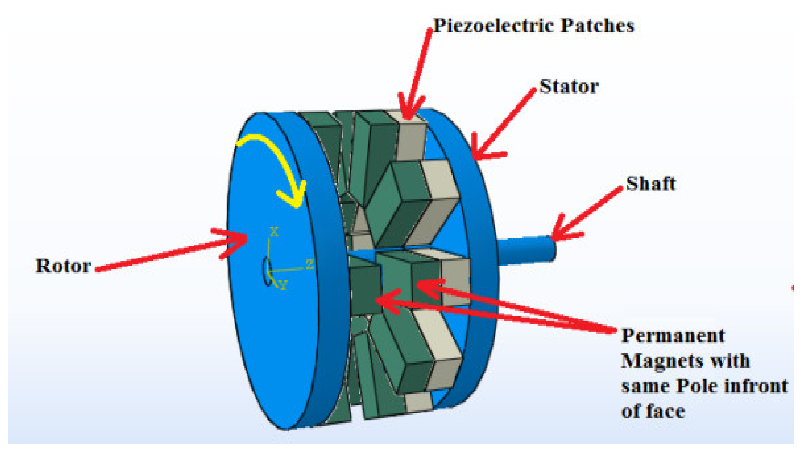
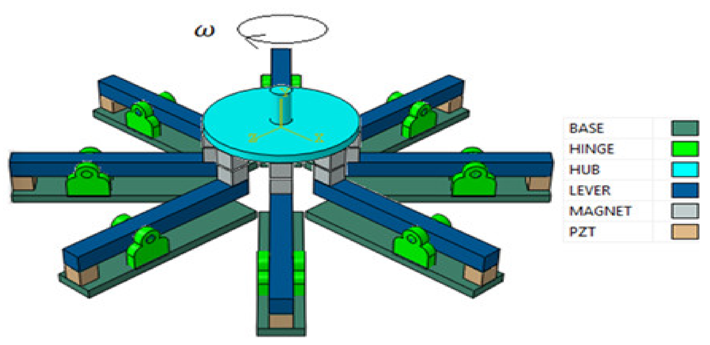
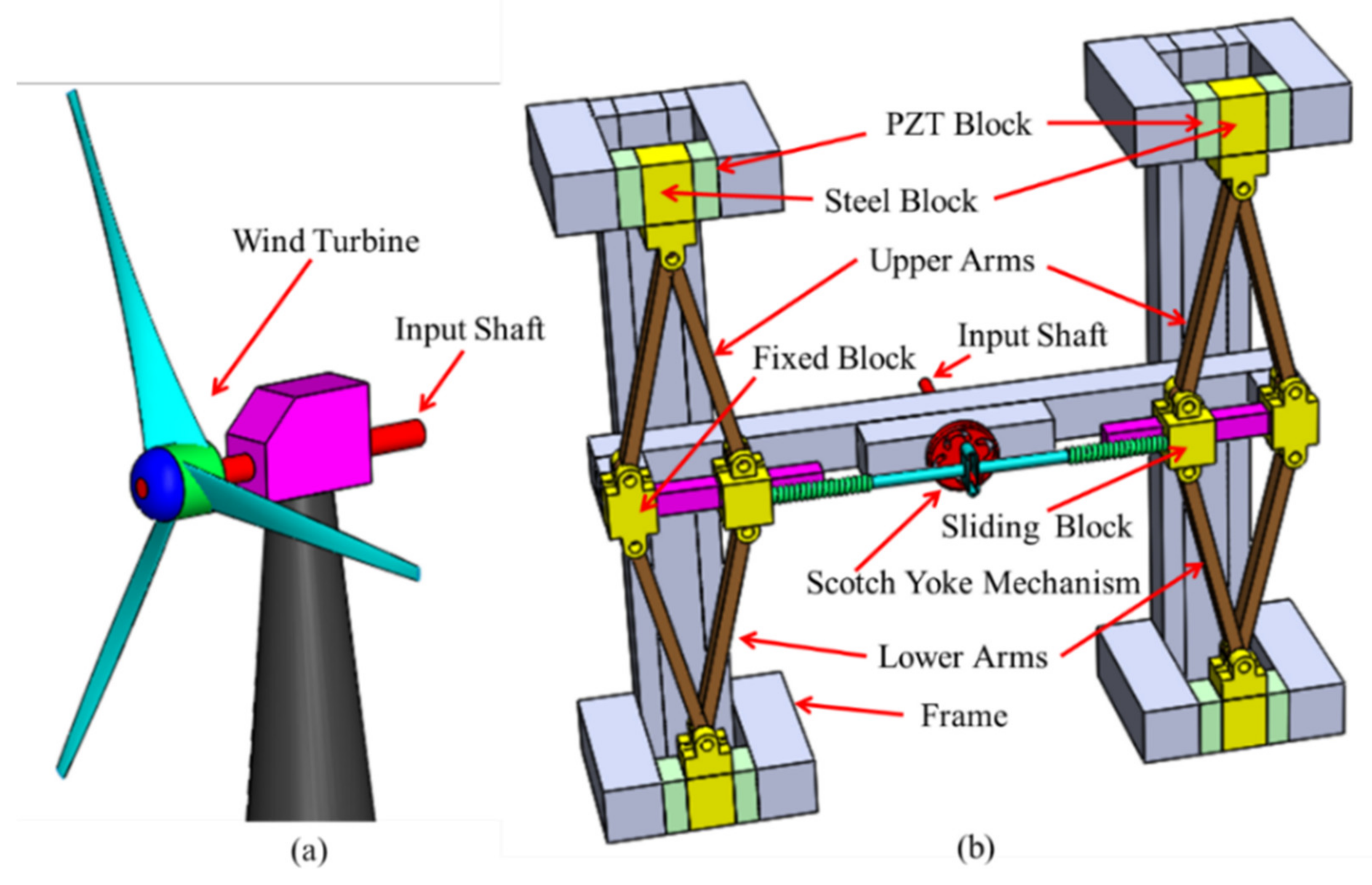
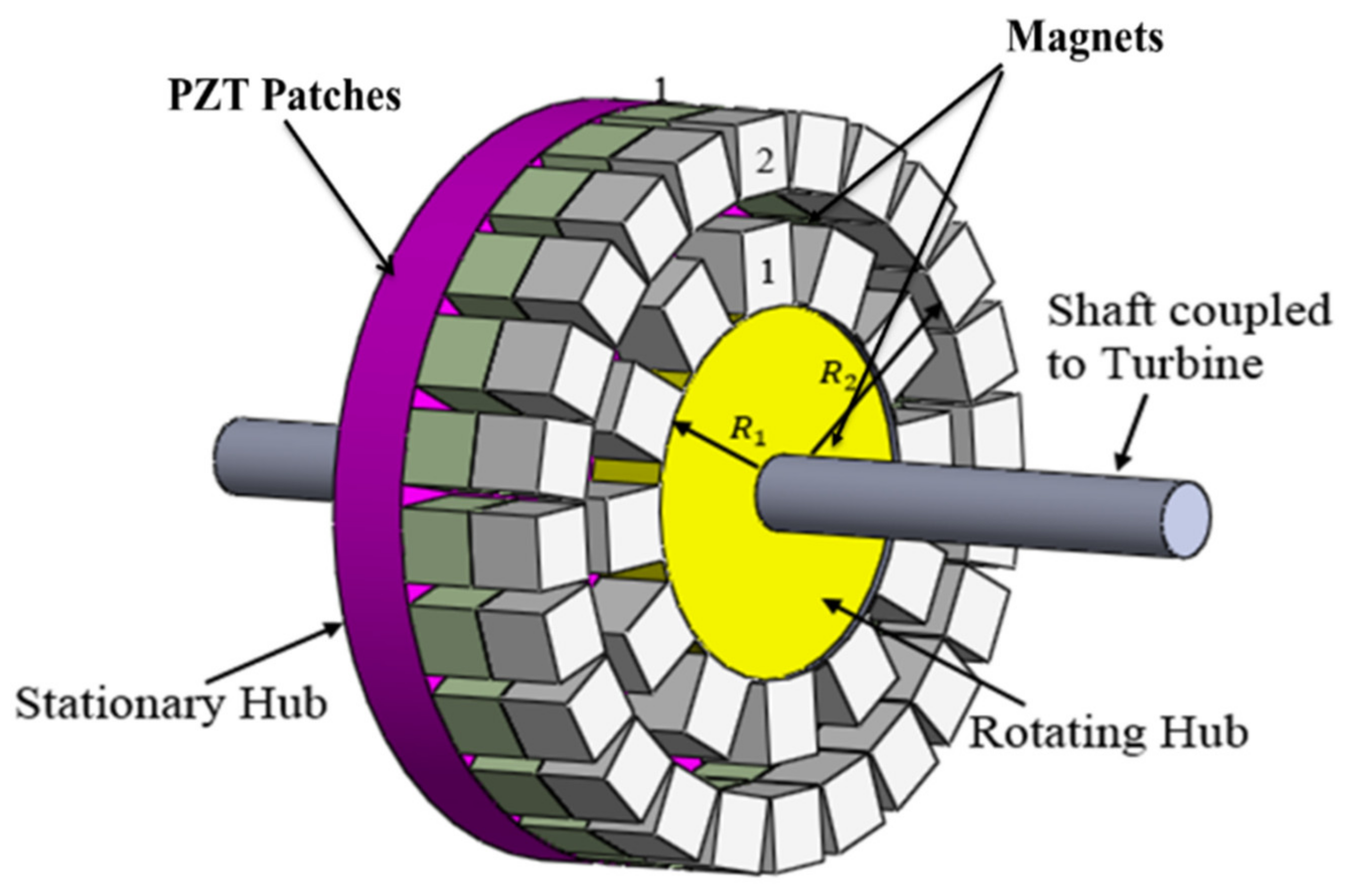
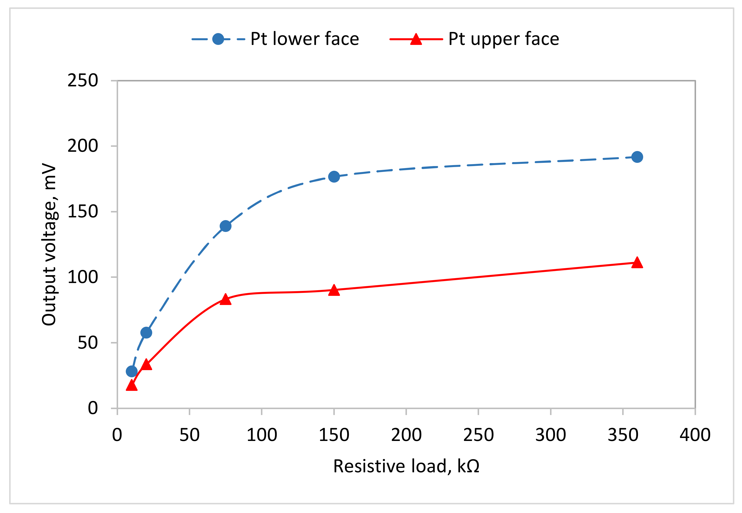
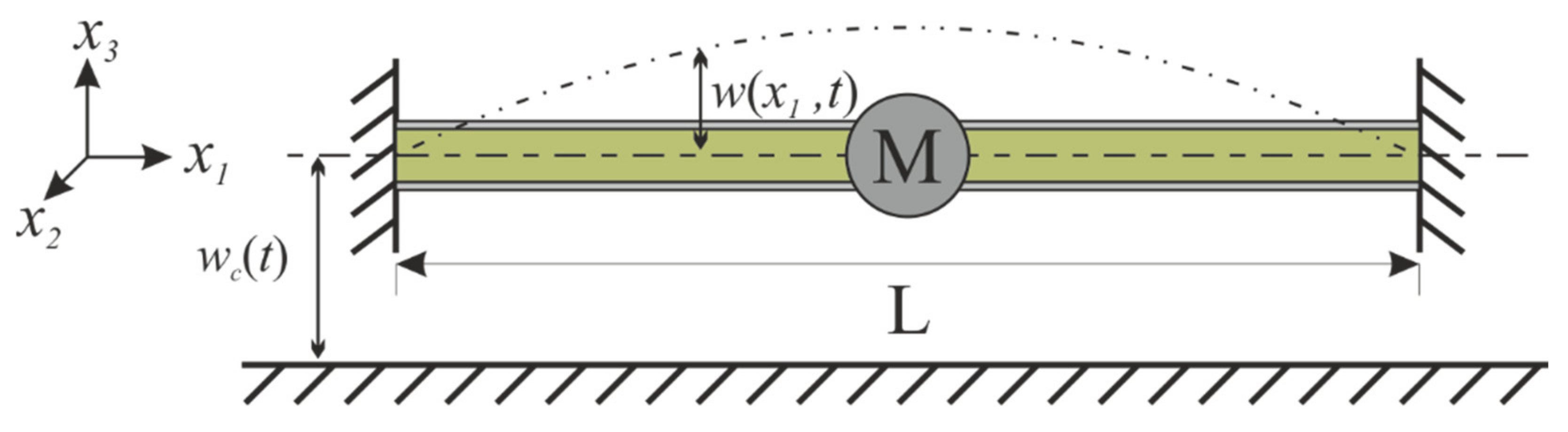
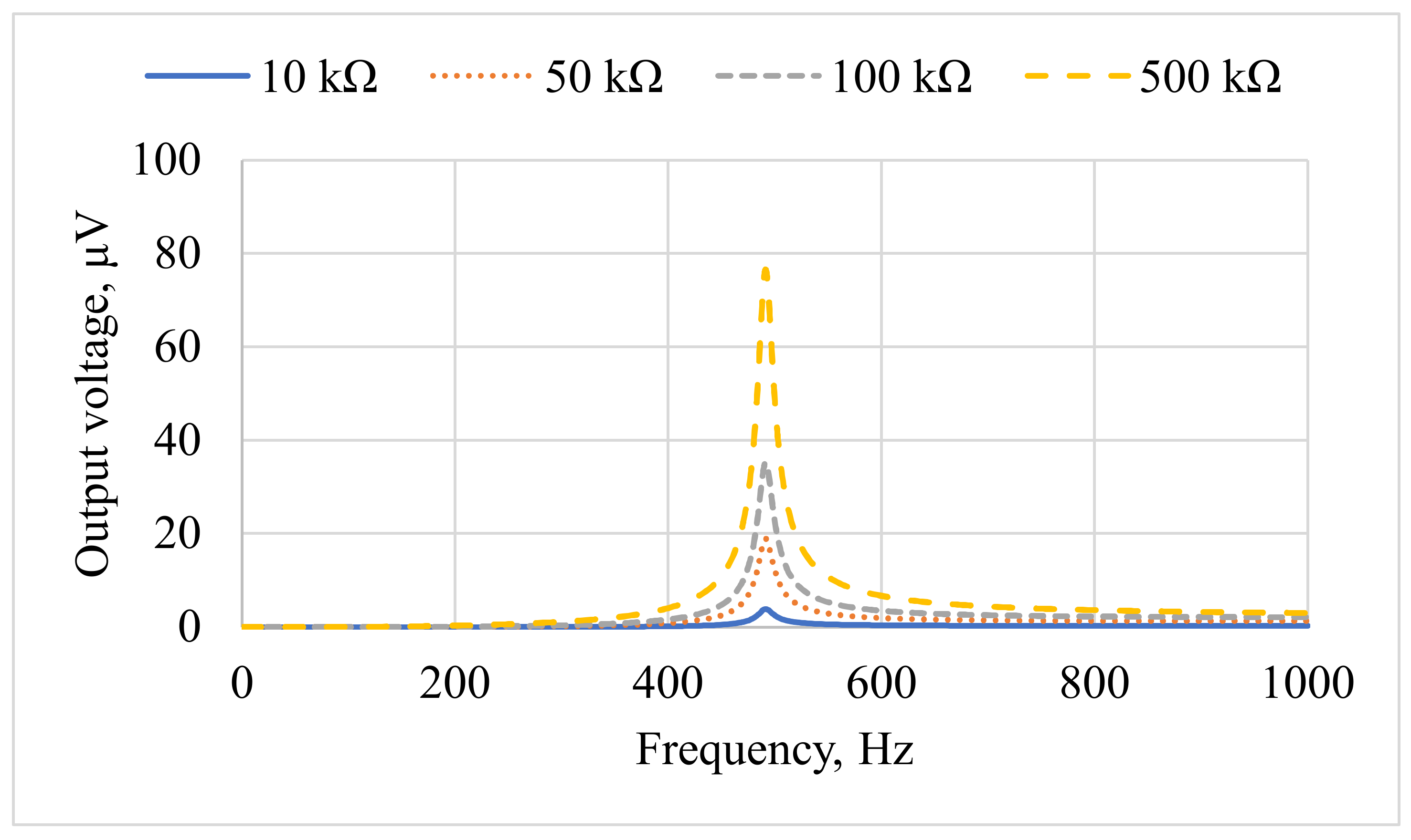
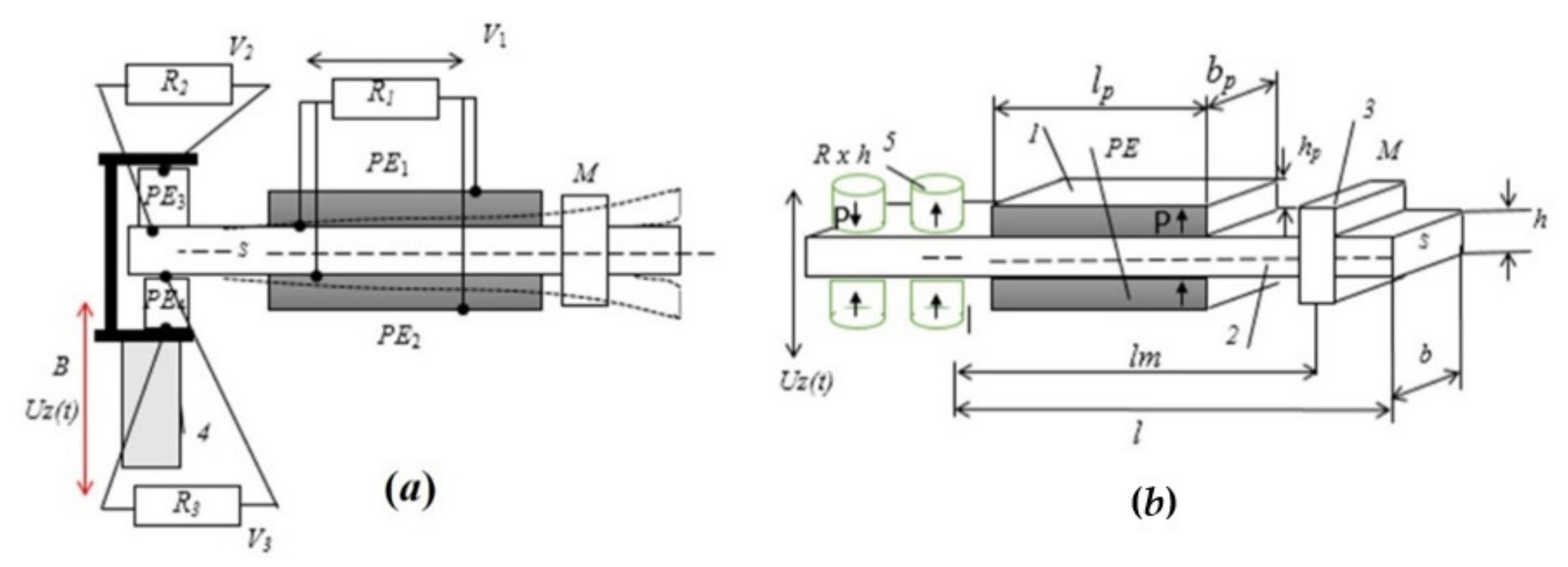
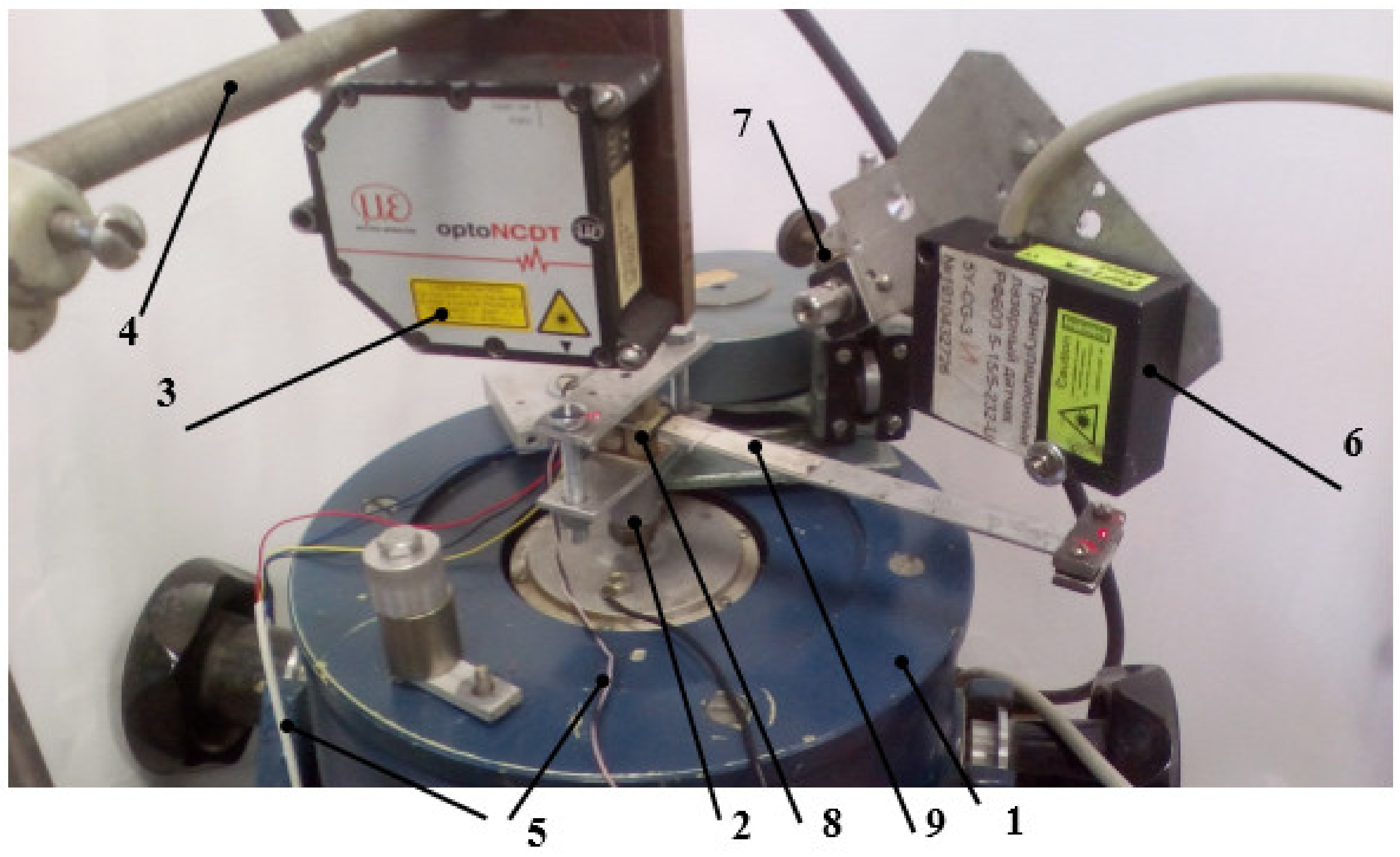
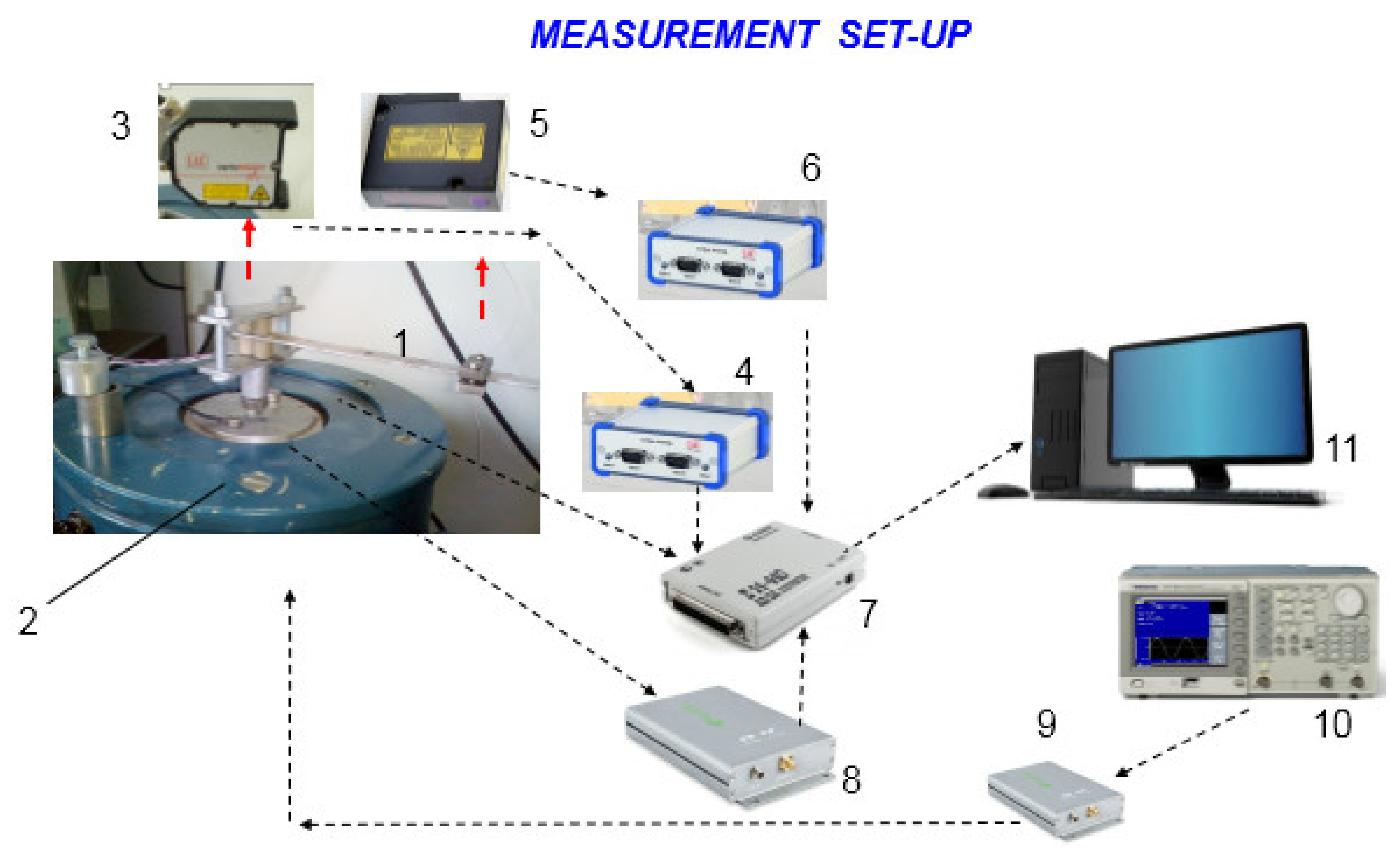
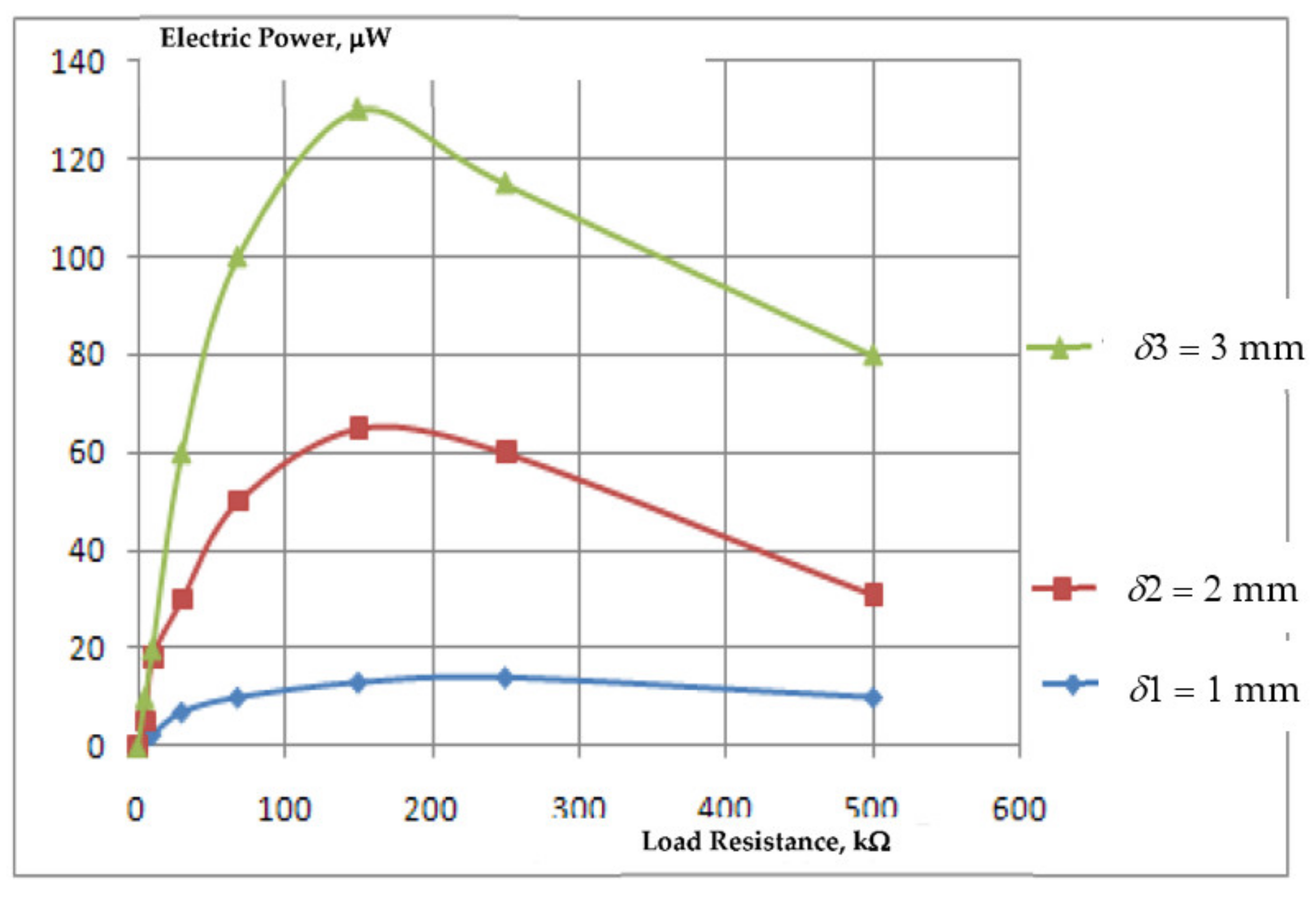
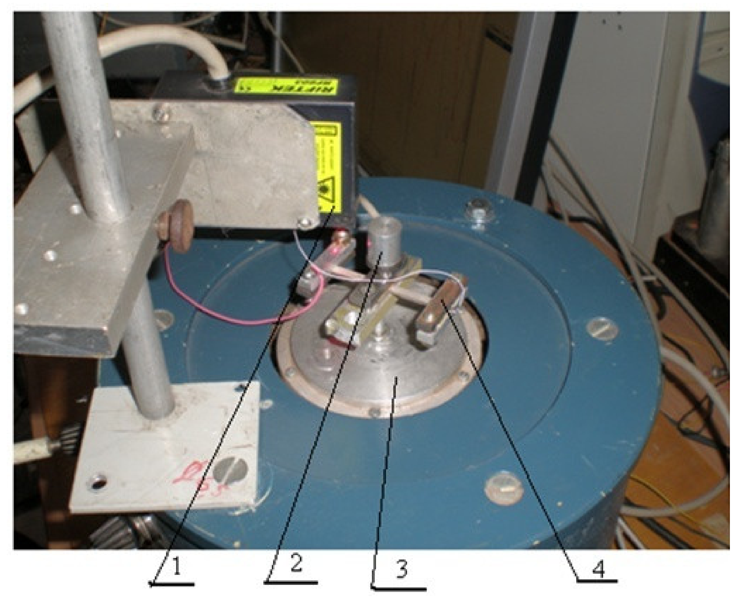
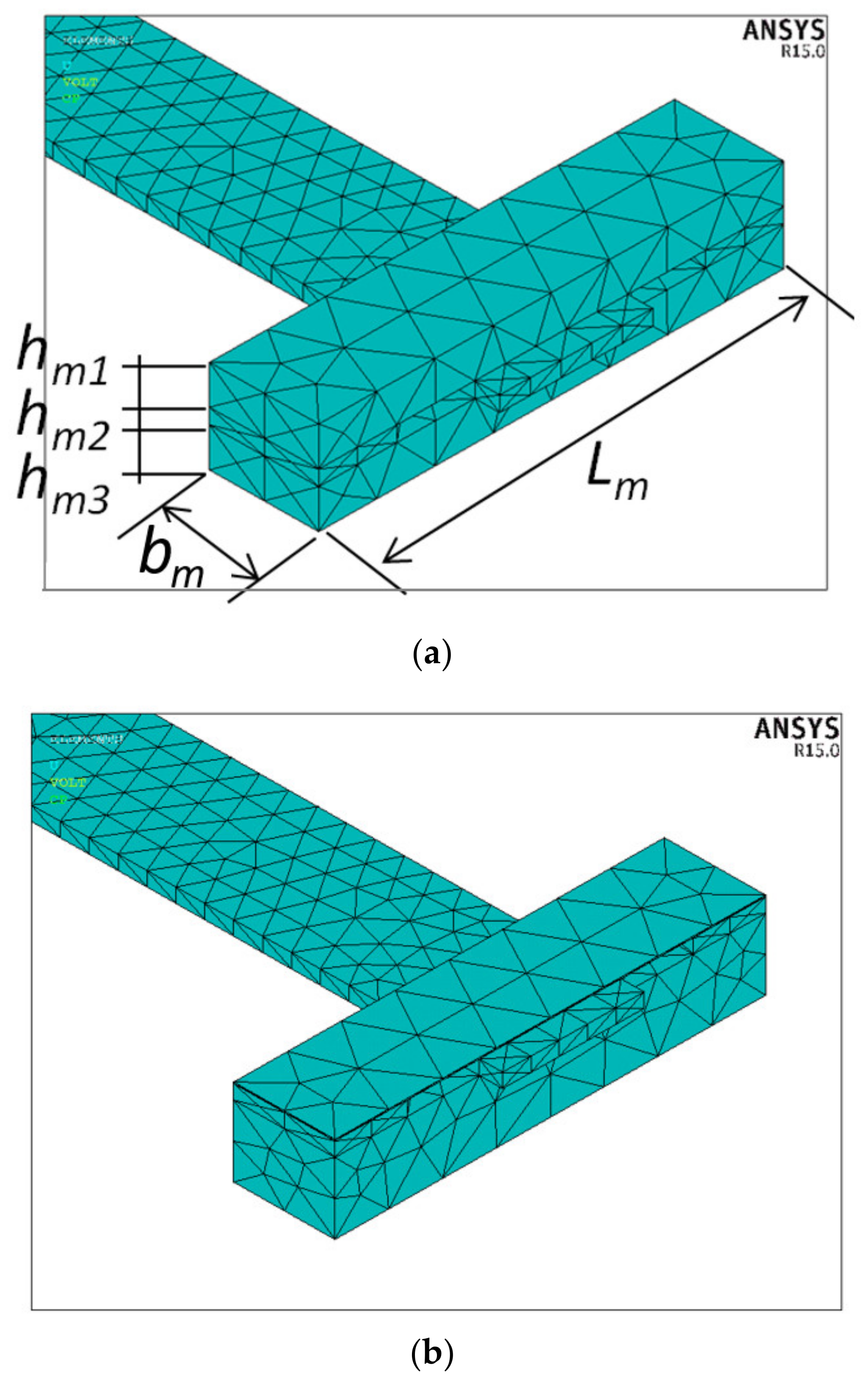
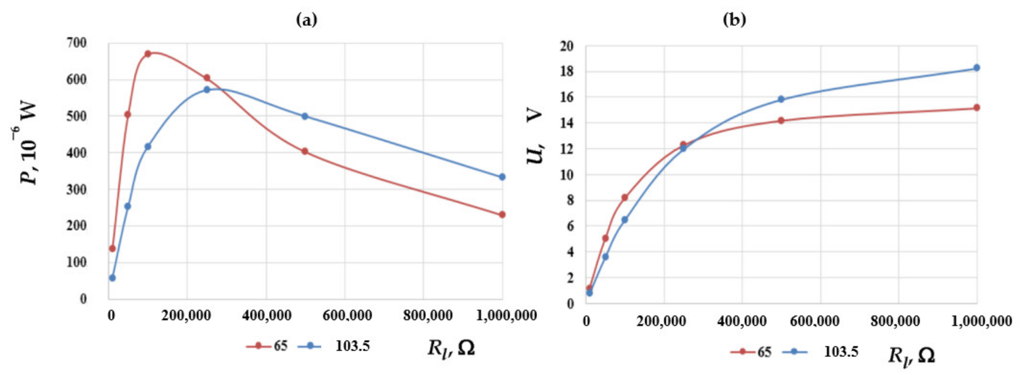
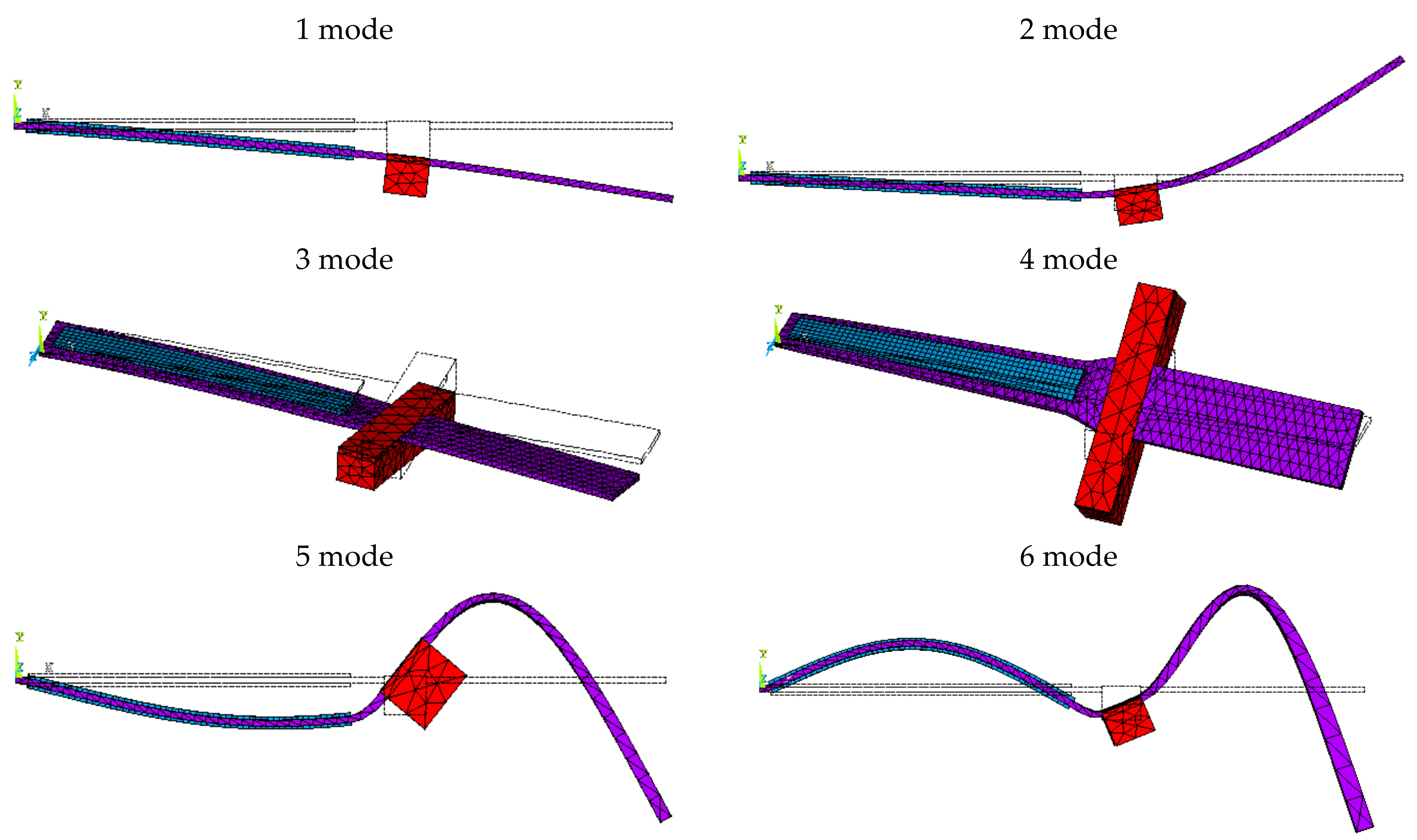
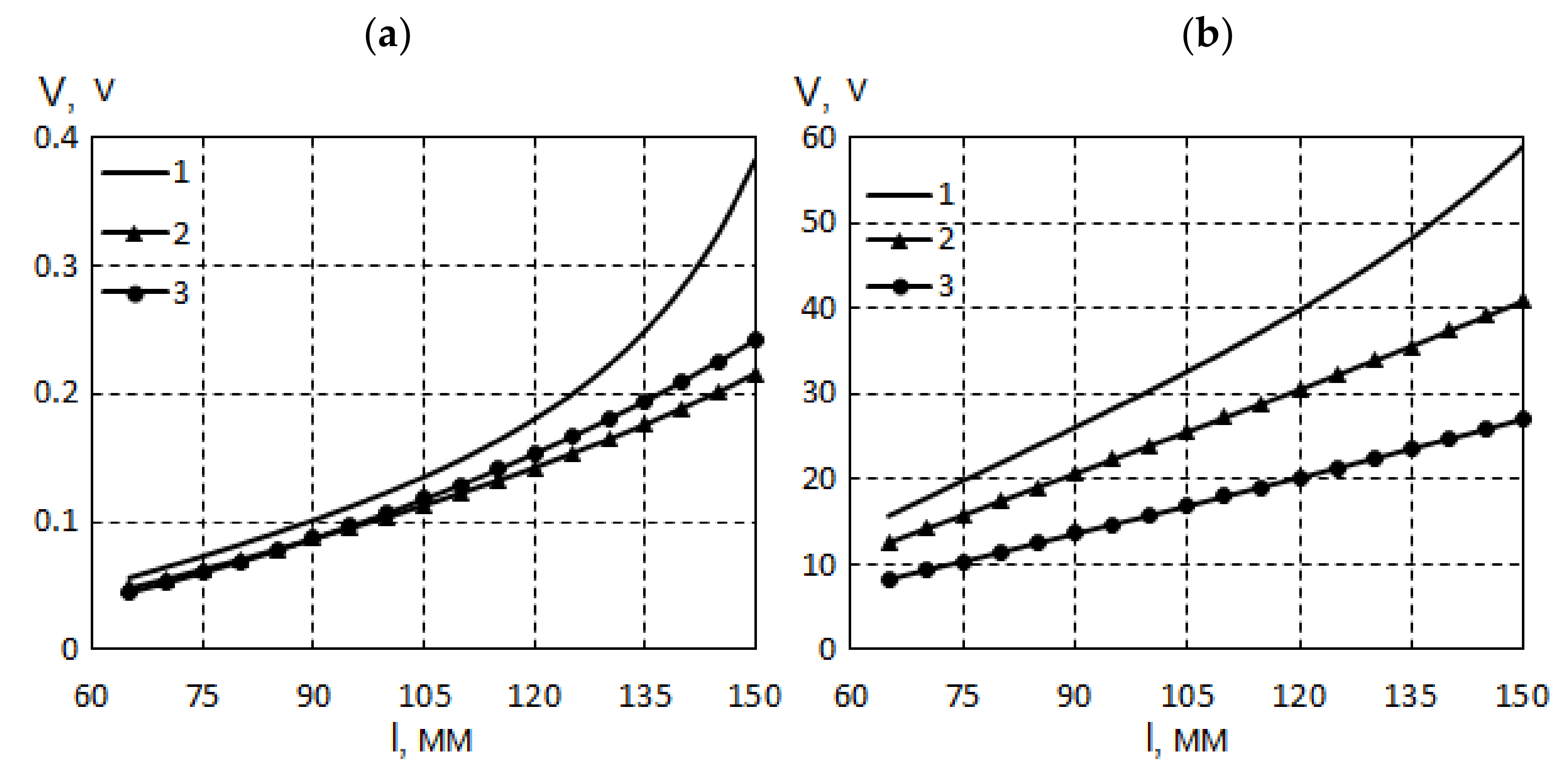
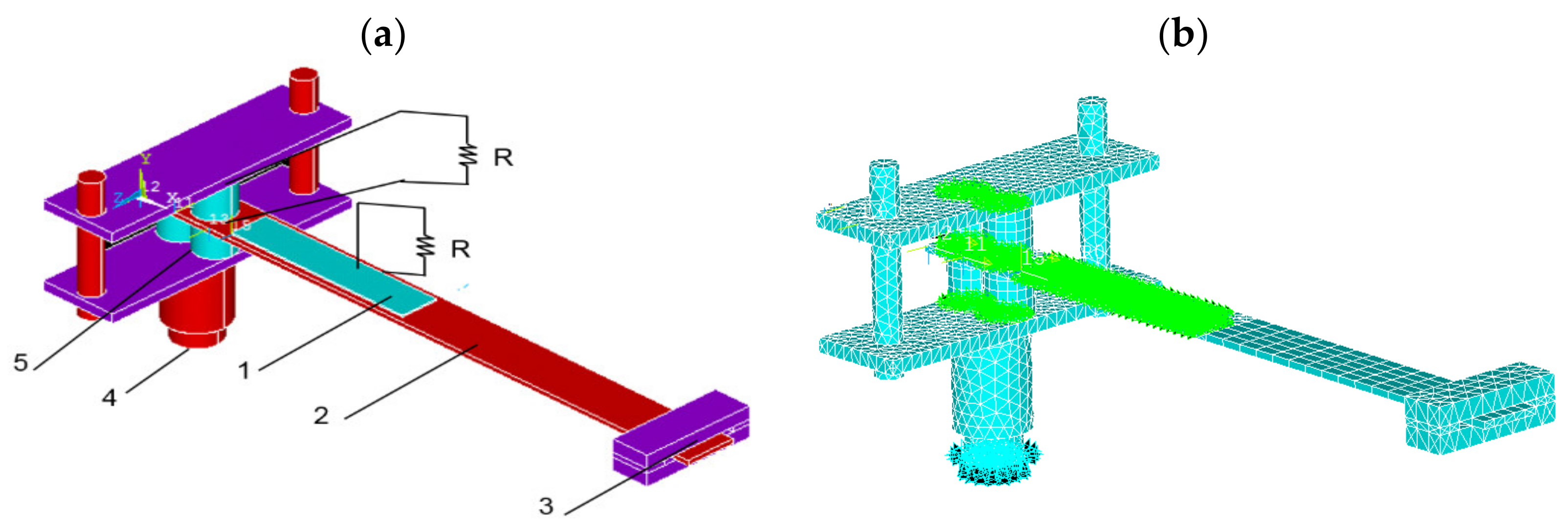
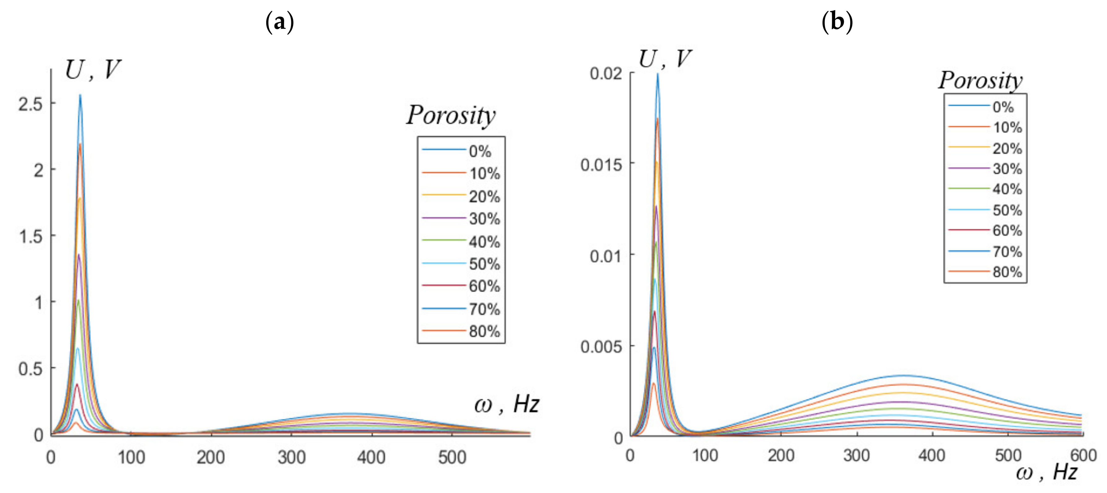
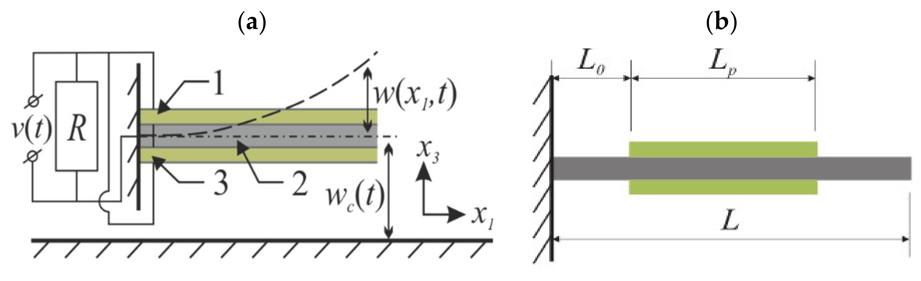
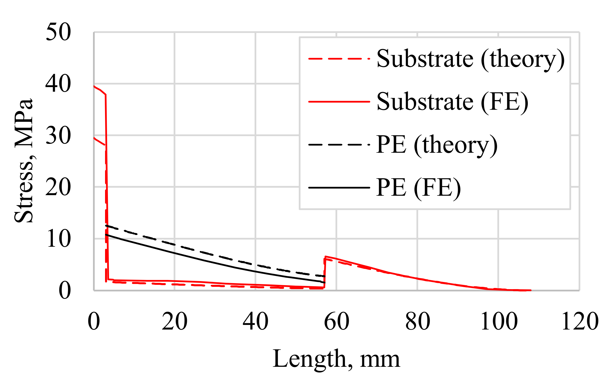
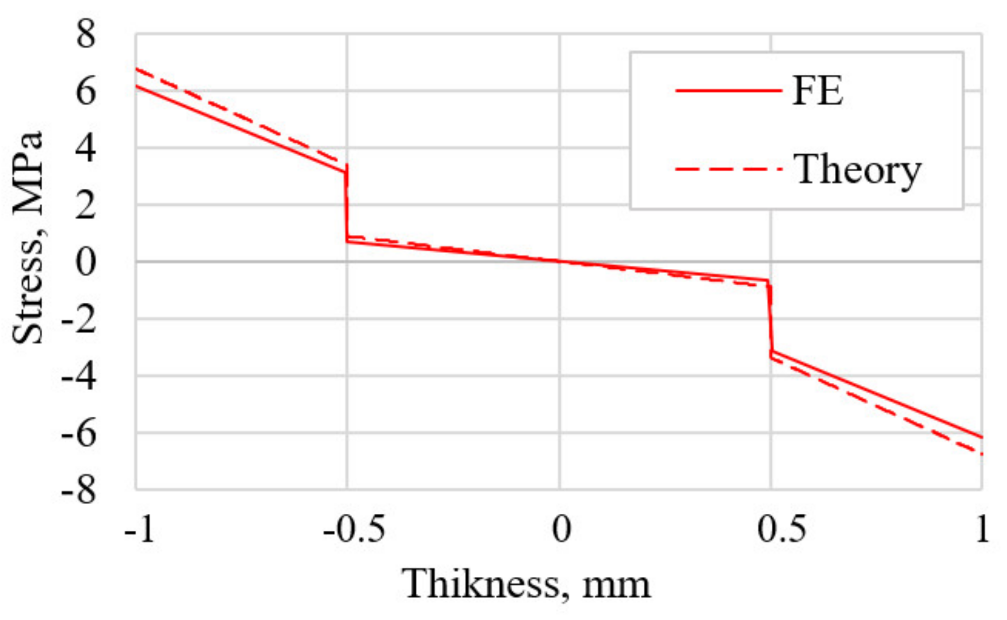
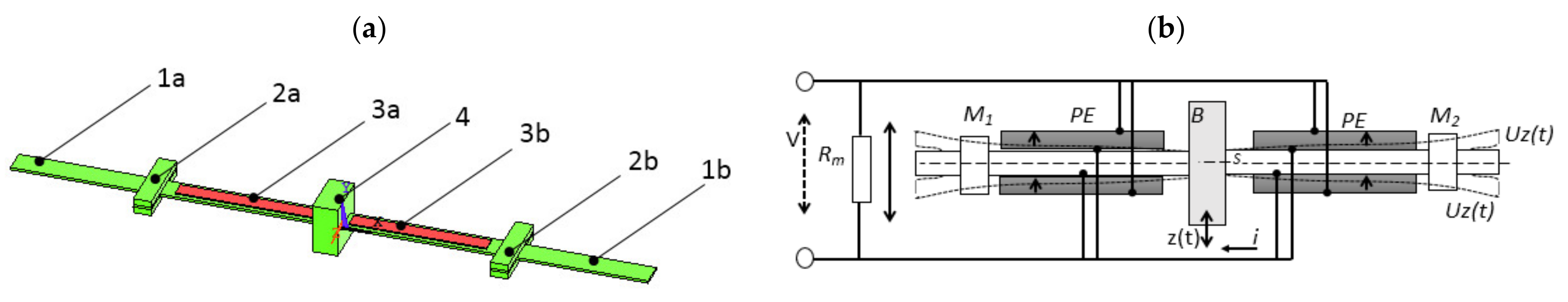
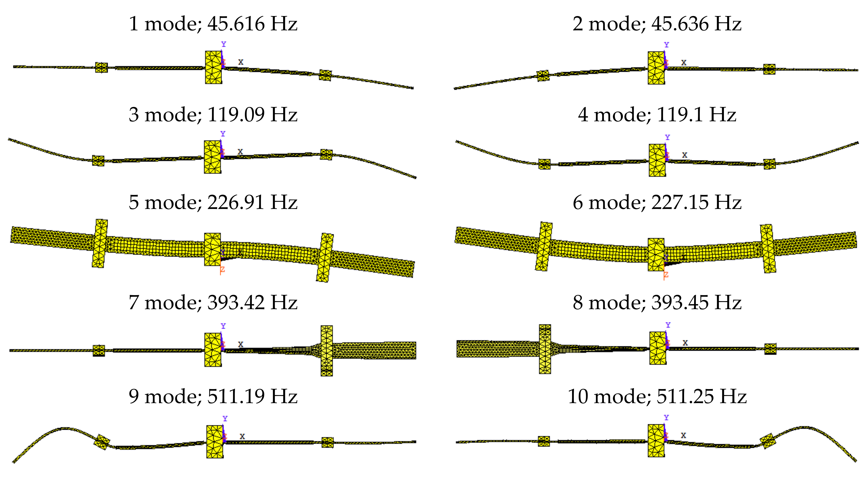
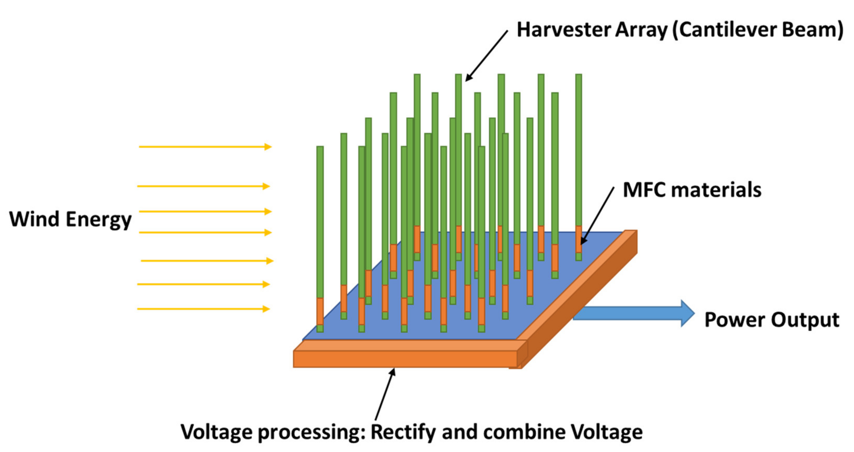
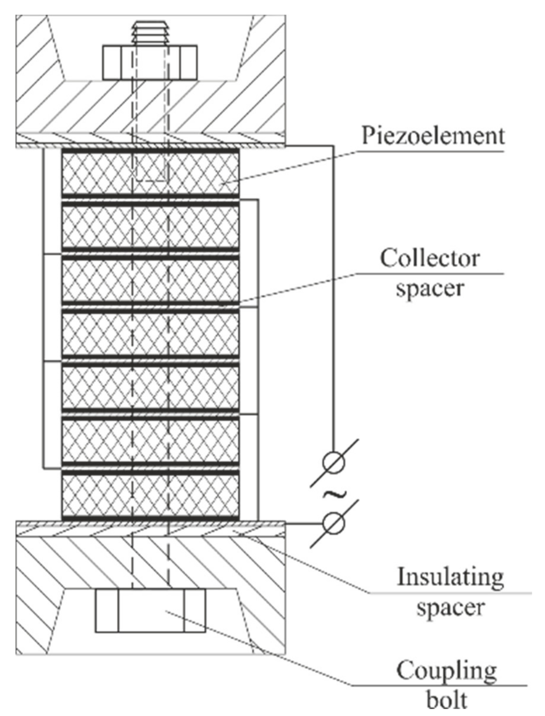
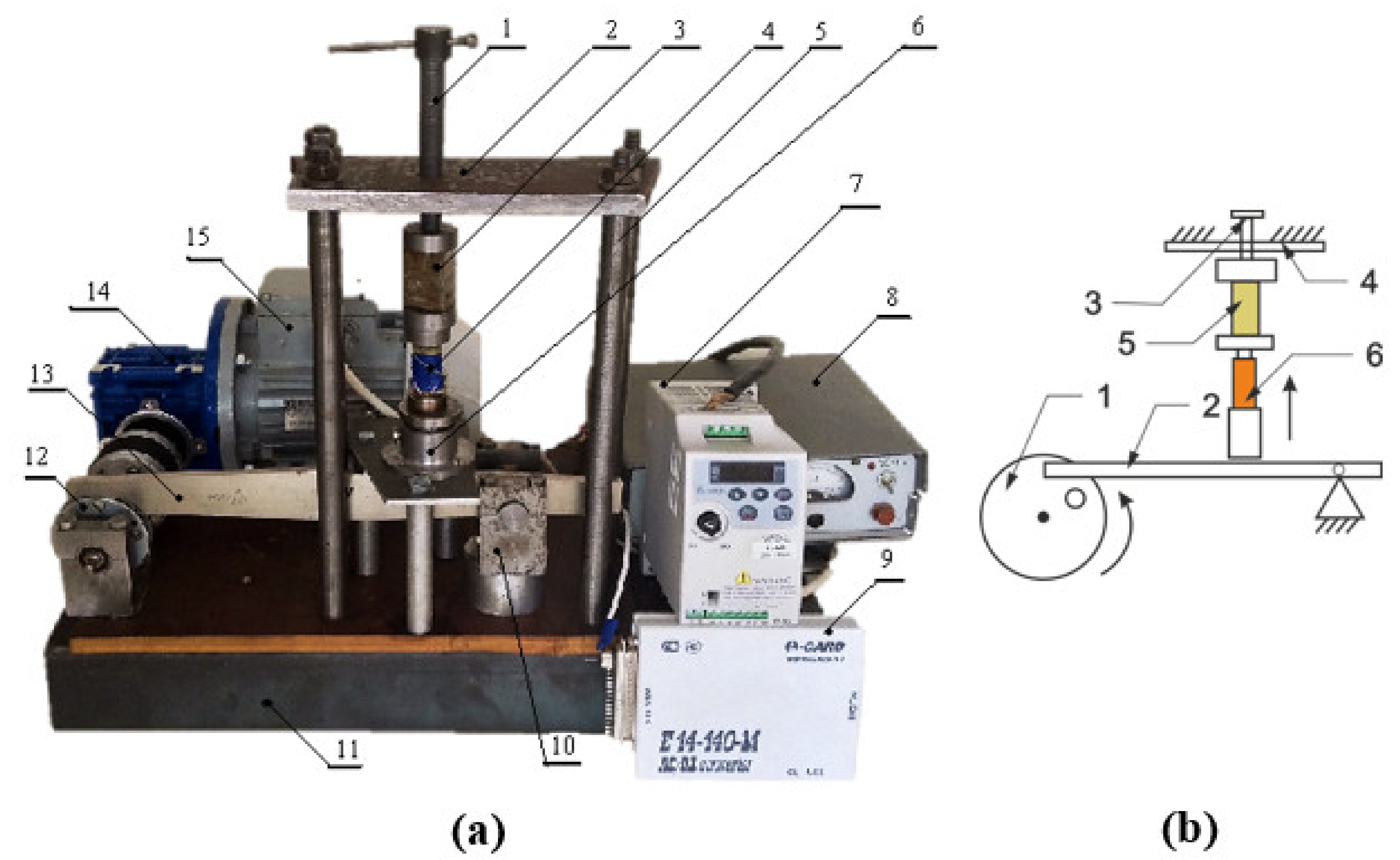
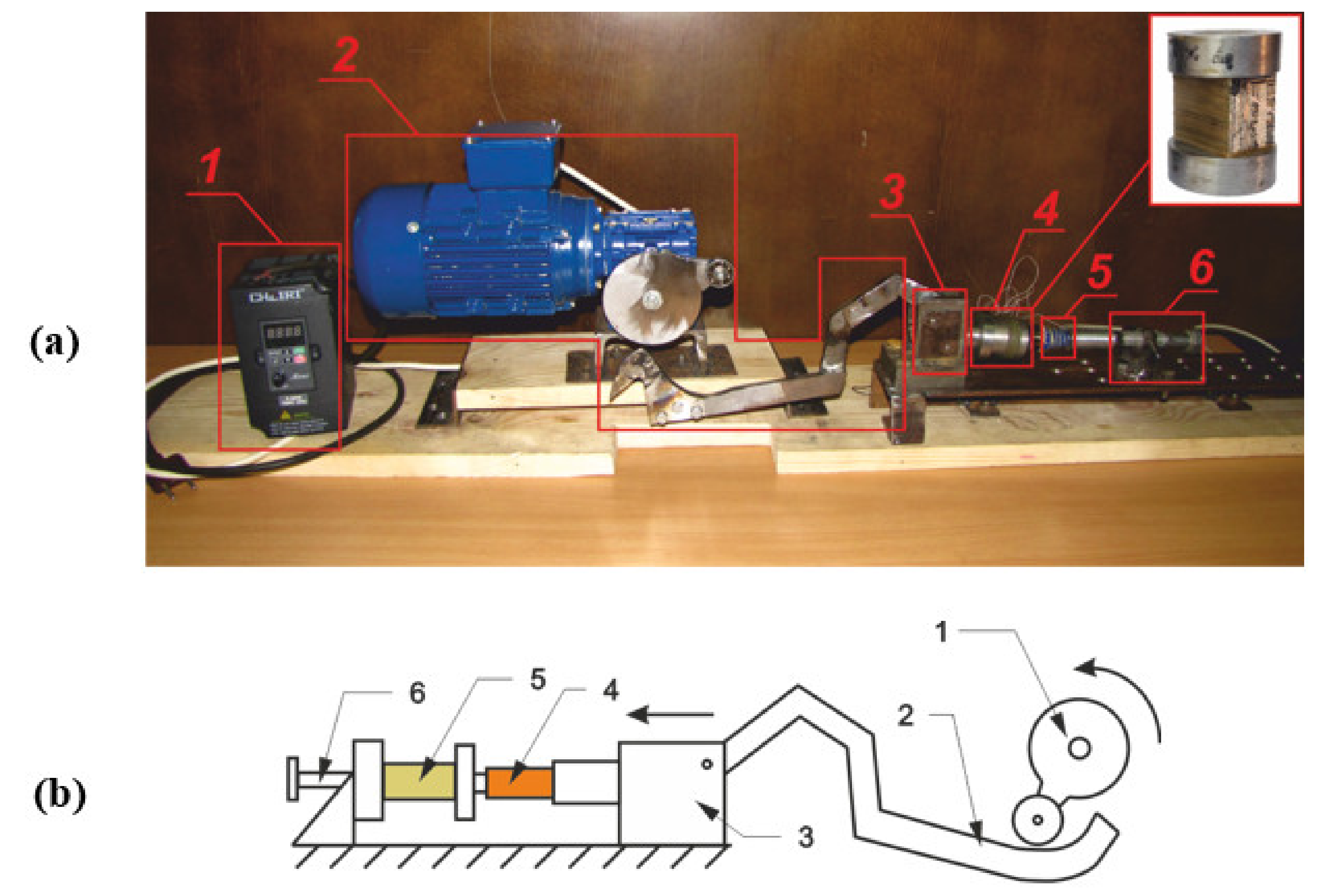
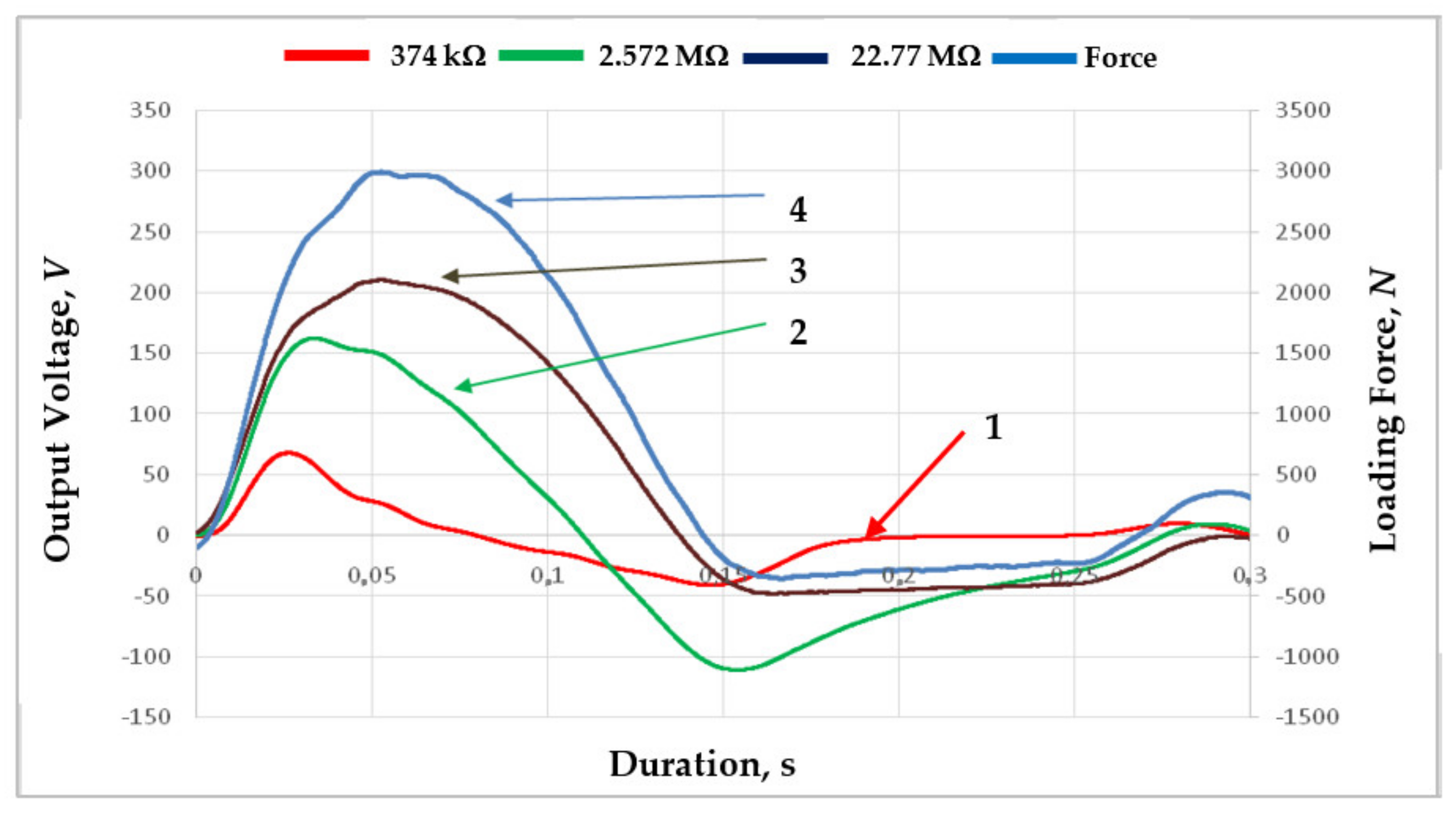
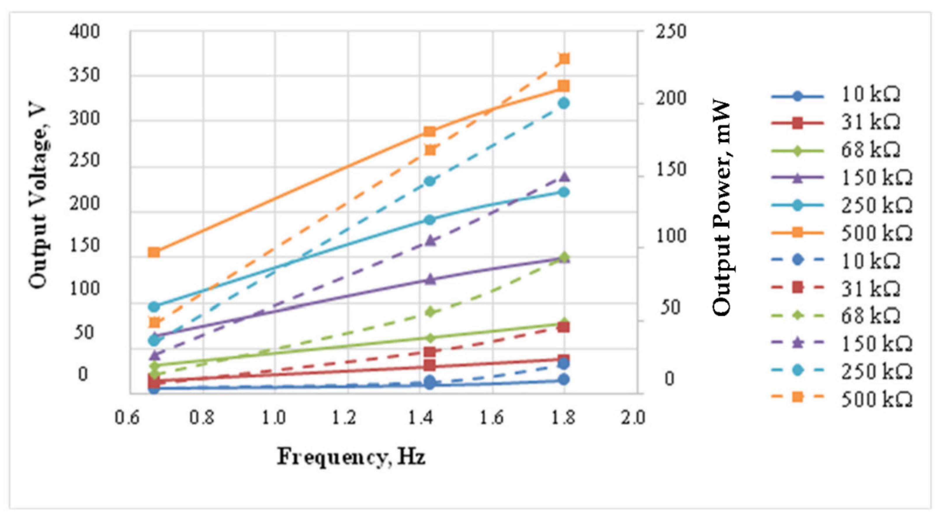
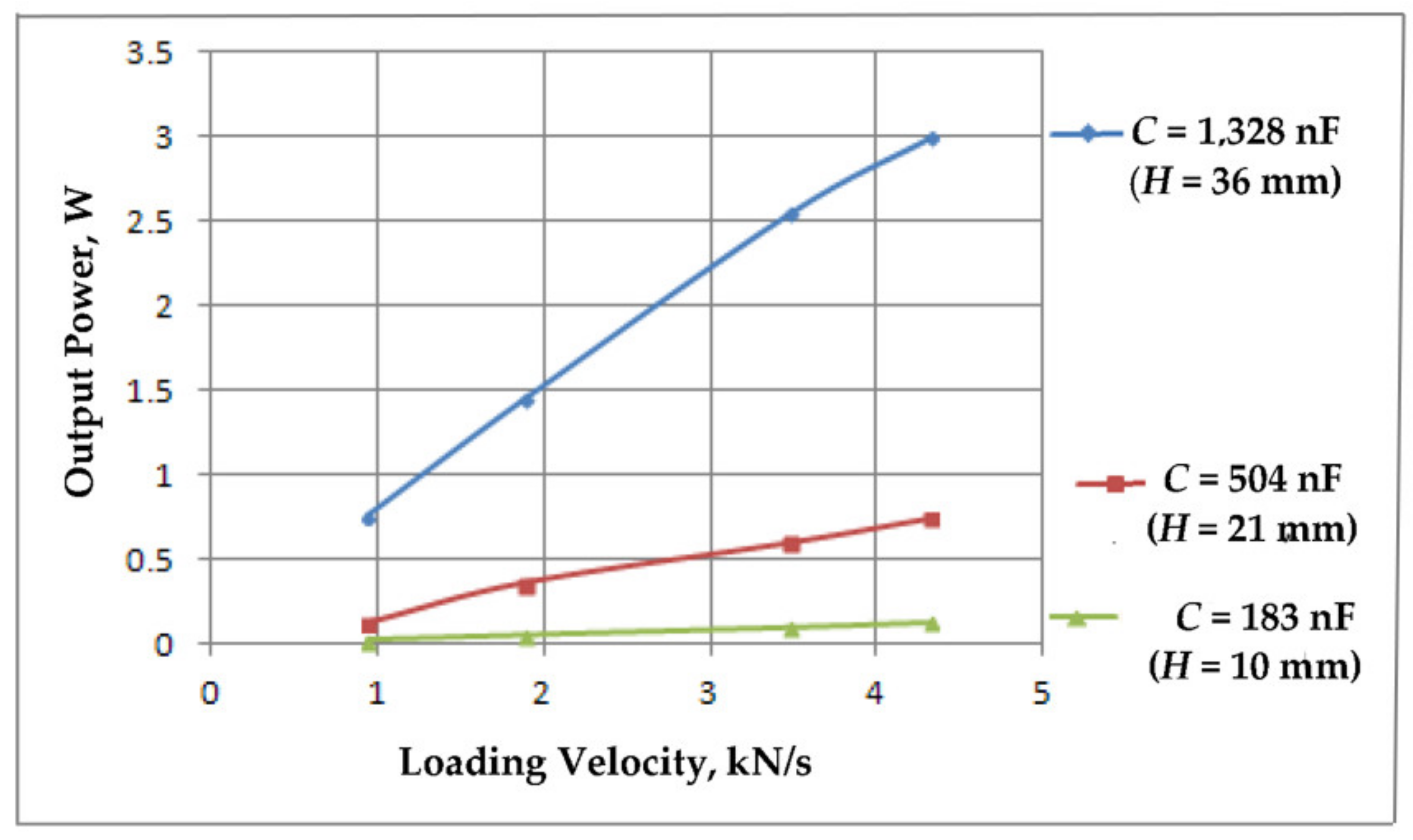
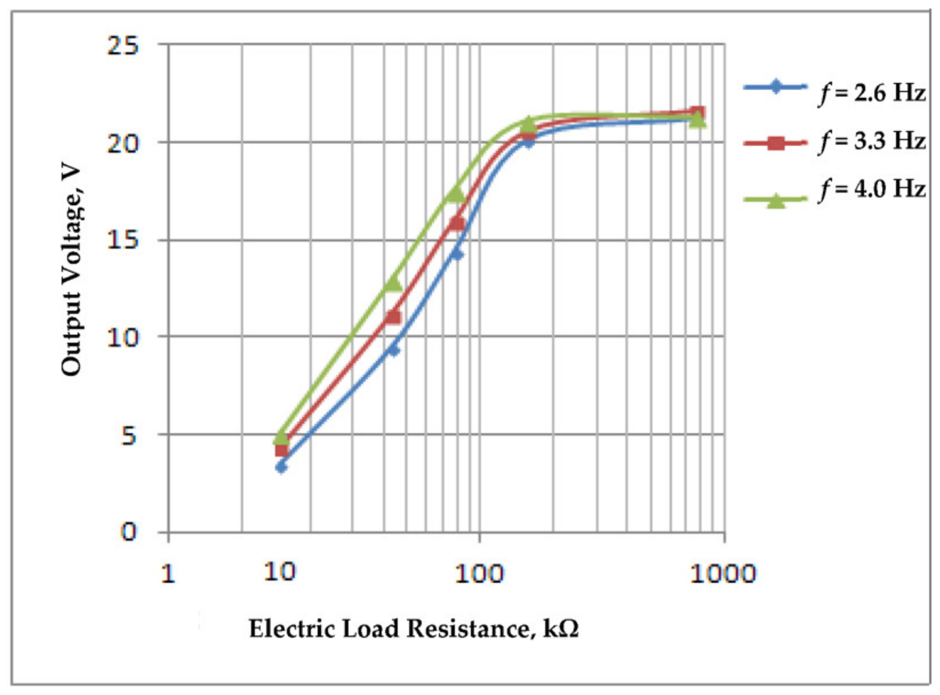
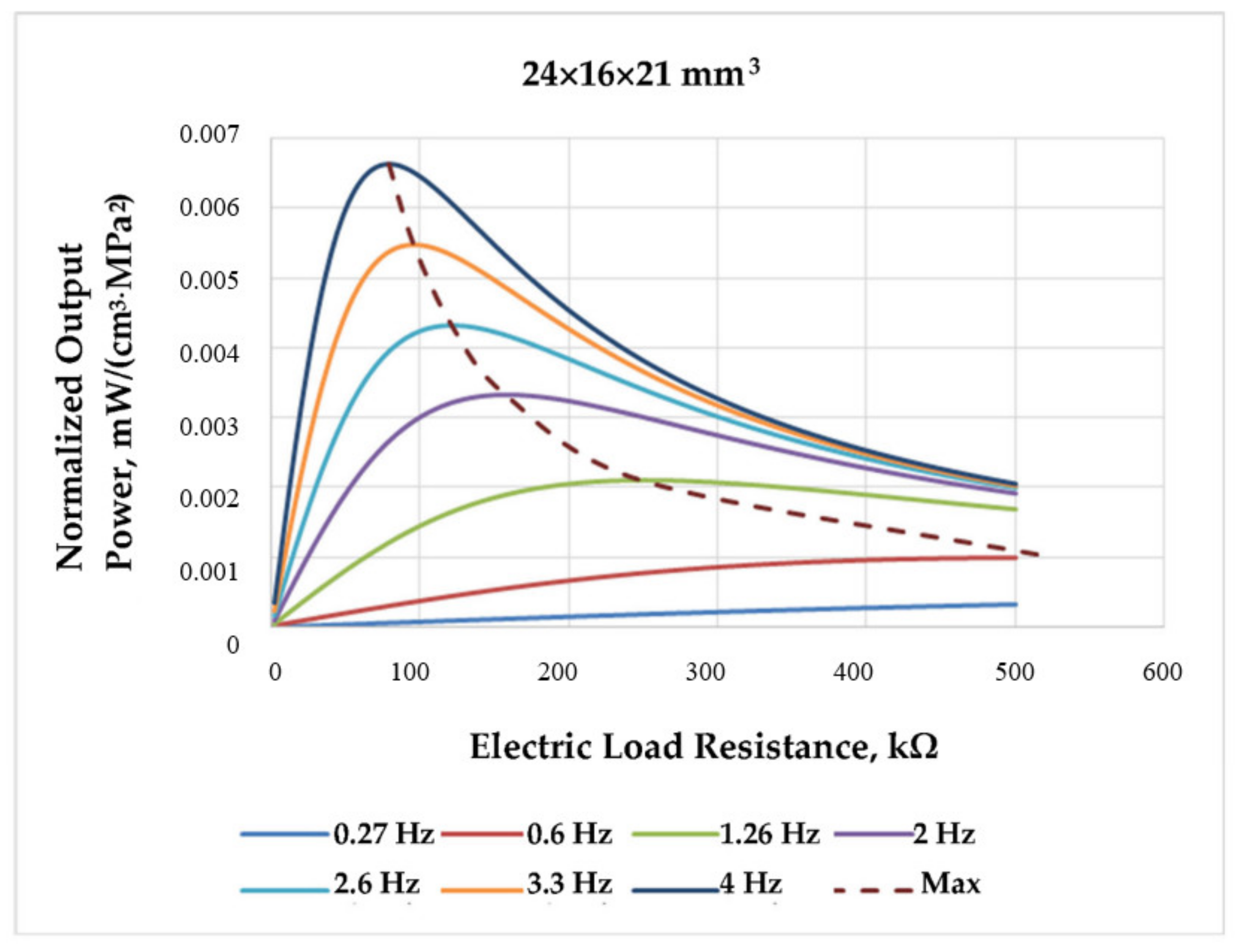
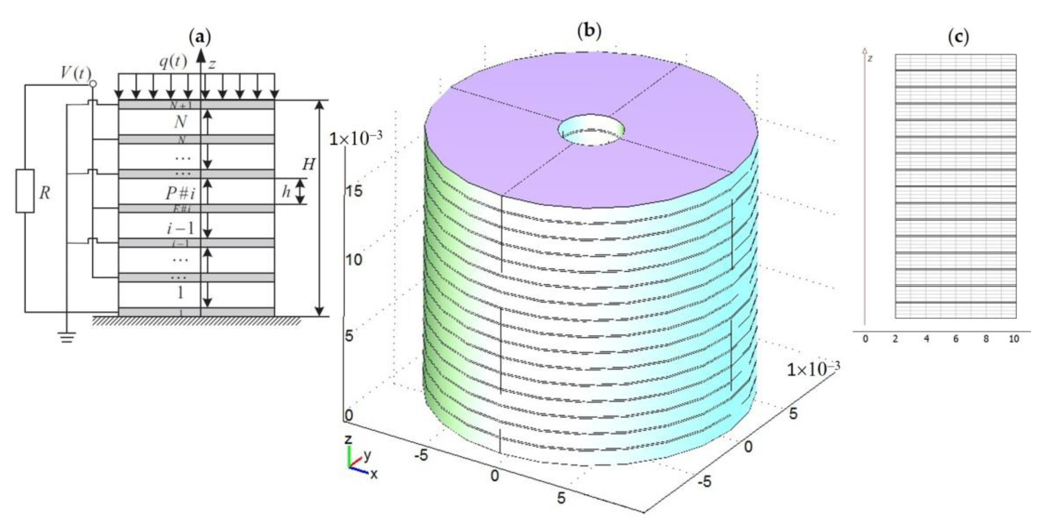
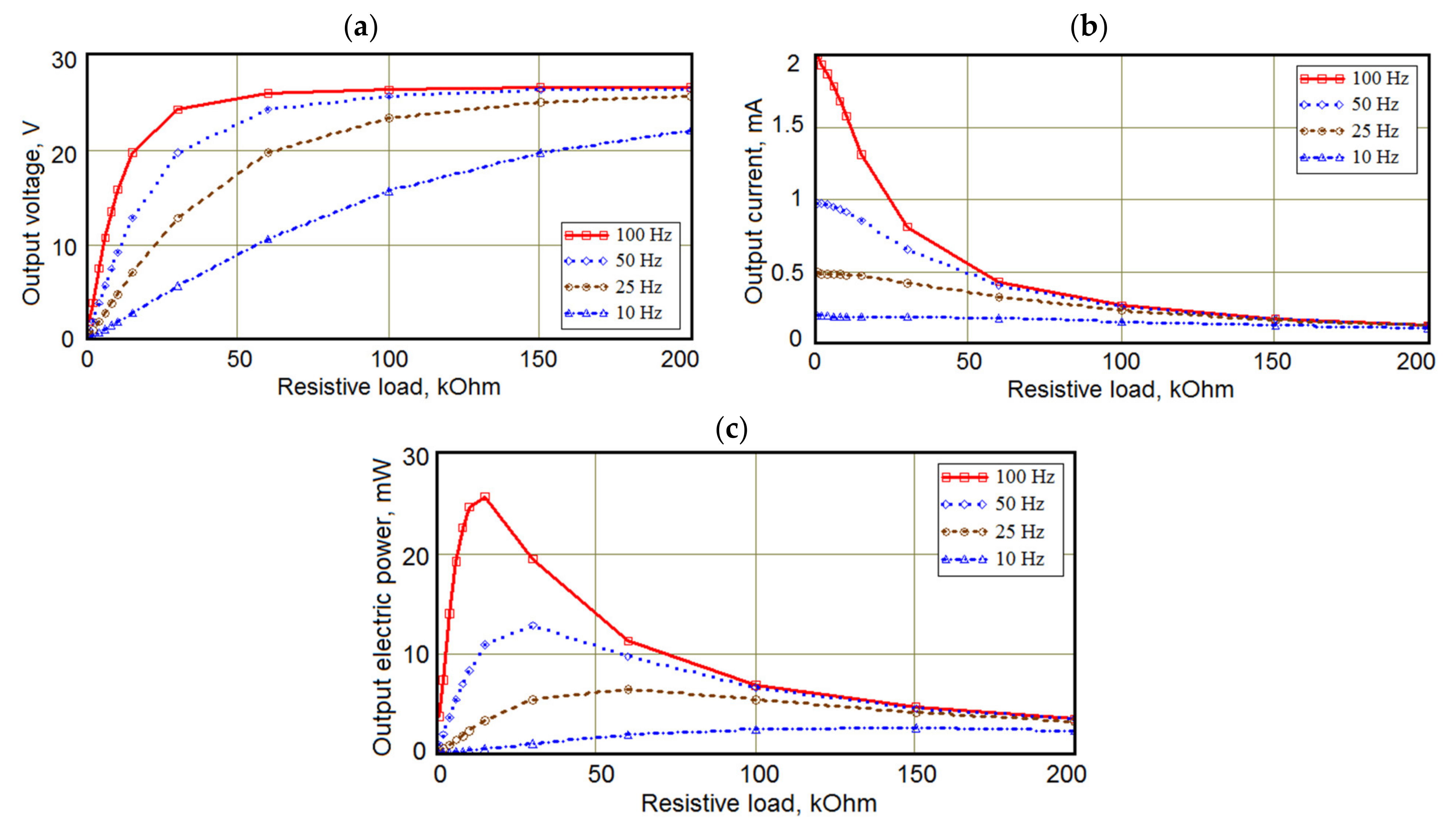
Table 1.
Comparison of electromechanical characteristics of some piezoelectrics at room temperature (from Bowen et al. [17], reproduced by permission of Springer Nature © 2022).
Table 1.
Comparison of electromechanical characteristics of some piezoelectrics at room temperature (from Bowen et al. [17], reproduced by permission of Springer Nature © 2022).
| d33, pC/N | d31, pC/N | d15, pC/N | k33 | |
|---|---|---|---|---|
| GaN | 3.7; 13.2 (NW) | −1.9; −9.4 (NW) | 3.1 | – |
| AlN | 5.0 | −2.0 | 3.6 | 0.23 |
| ZnO | 12.4; 14.3–26.7 (nanobelt) | −5.0 | −8.3 | 0.48 |
| BaTiO3, FC | 149 | −58 | 242 | 0.49 |
| PZT-4 (hard FC) | 289 | −123 | 495 | 0.70 |
| PZT-5H (soft FC) | 593 | −274 | 741 | 0.75 |
| PMN–0.33PT, SC | 2820 | −1330 | 146 | 0.94 |
| LiNbO3, SC | 6 | −1.0 | 69 | 0.23 |
| Poled PVDF | −33 | 21 | −27 | 0.19 |
Designations: nanowires (NW); single crystal (SC); ferroelectric ceramic (FC); polyvinylidene fluoride (PVDF); dij are the piezoelectric factors; and k33 is the electromechanical coupling factor (ECF) at the longitudinal oscillation mode.
Publisher’s Note: MDPI stays neutral with regard to jurisdictional claims in published maps and institutional affiliations. |
© 2022 by the authors. Licensee MDPI, Basel, Switzerland. This article is an open access article distributed under the terms and conditions of the Creative Commons Attribution (CC BY) license (https://creativecommons.org/licenses/by/4.0/).
Share and Cite
MDPI and ACS Style
Parinov, I.A.; Cherpakov, A.V. Overview: State-of-the-Art in the Energy Harvesting Based on Piezoelectric Devices for Last Decade. Symmetry 2022, 14, 765. https://doi.org/10.3390/sym14040765
AMA Style
Parinov IA, Cherpakov AV. Overview: State-of-the-Art in the Energy Harvesting Based on Piezoelectric Devices for Last Decade. Symmetry. 2022; 14(4):765. https://doi.org/10.3390/sym14040765
Chicago/Turabian StyleParinov, Ivan A., and Alexander V. Cherpakov. 2022. "Overview: State-of-the-Art in the Energy Harvesting Based on Piezoelectric Devices for Last Decade" Symmetry 14, no. 4: 765. https://doi.org/10.3390/sym14040765
Note that from the first issue of 2016, this journal uses article numbers instead of page numbers. See further details here.