Article

Hybrid Precoding-Based Millimeter Wave Massive MIMO-NOMA Systems

1
School of Physics and Electronics, Central South University, Lushan South Road, Changsha 410083, China
2
College of Information Science and Engineering, Changsha Normal University, Teli Road, Changsha 410100, China
*
Author to whom correspondence should be addressed.
Symmetry 2022, 14(2), 412; https://doi.org/10.3390/sym14020412
Submission received: 23 January 2022 / Revised: 16 February 2022 / Accepted: 17 February 2022 / Published: 19 February 2022
(This article belongs to the Special Issue Symmetry/Asymmetry in Wireless Communication and Sensor Networks)

Abstract

:
A symmetry-based hybrid precoder and combiner is a high spectral efficiency structure in millimeter-wave (mmWave) massive multiple-input multiple-output (mMIMO) non-orthogonal multiple access (NOMA) system. To improve the spectral efficiency of the mmWave mMIMO-NOMA system, we first propose a user grouping scheme to suppress the strong inter-user interference caused by NOMA, then the hybrid precoder based on user channel alignment and the zero-forcing algorithm is constructed to further improve the signal-to-interference-plus-noise ratio (SINR) of the receiver. Subsequently, the non-convex spectral efficiency optimization problem is transformed into a convex optimization problem of inter-cluster power allocation and the closed-form solution for the optimal power under the minimum rate constraint is obtained by solving the KKT condition to further improve the spectral efficiency. The simulation results show that the proposed scheme can achieve higher spectral efficiency compared to orthogonal multiple access (OMA), fixed power allocation (FPA), K-means, and cluster head selection (CHS).

1. Introduction

The mMIMO communication networks which operate in the mmWave band are characterized by high frequency and a larger number of antennas, resulting in high path loss, large power consumption, and server interference. These problems make the spectrum efficiency largely reduced; therefore, how to improve the spectral efficiency is a significant research issue for 6G communication [1,2]. The MIMO-NOMA technology based on NOMA can serve multiple users in the same time-frequency domain, which can vastly improve spectral efficiency [3,4]. However, there are two serious technical obstacles in the mMIMO-NOMA communication system, The first problem is that the number of users is much larger than the number of radio frequency (RF) chains, which can lead to severe inter-beam and intra-beam interference, i.e., inter-user interference problem [5,6]. The other problem is that the number of users in the 6G communication system has increased dramatically, making the energy consumption greatly increased, i.e., power allocation problem [7]. Therefore, inter-user interference and power allocation are the two essential challenges that need to be solved in 6G communication systems.
The existing research has been conducted to eliminate the inter-user interference by performing user grouping and hybrid precoder and utilizing the power allocation algorithm to further optimize the spectral efficiency. Several works have been focused on designing user grouping algorithms to suppress inter-user interference. The researchers in [8] applied the NOMA technology to mMIMO for the first time and significantly improved the system performance compared to the MIMO-OMA system, but the work did not consider the design of user grouping scheme to suppress the inter-user interference. The researchers in [9] proposed a K-means user grouping algorithm that iteratively divides the user based on the channel correlation of users to obtain the local optimal solution for user grouping. However, the performance of the K-means algorithm easily depends on the selection of the initial cluster heads, and the selected initial cluster heads affect the results of user grouping. The researchers in [10] improved the K-means algorithm to reduce interference by optimizing the initial selection of cluster heads, but the computational complexity of the algorithm is so high that the time cost is high. The researchers in [11] proposed a low-complexity cluster heads selection algorithm, the initial cluster heads are selected by calculating the channel correlation of users, and then the minimum channel correlation of users are selected as the initial cluster heads, but the work does not iteratively group the remaining users, resulting in less accurate user grouping results. In addition, some studies have been focused on the design of a hybrid precoder to further eliminate the inter-user interference. The researchers in [12] proposed a low-complexity hybrid precoder design scheme to eliminate the inter-user interference, but the work only considers the two-user case and is not extended to the multi-user case. The researchers in [13] studied the hybrid precoder in the K-user case, and jointly optimize the hybrid precoder and user grouping to significantly improve the system performance, but the computational complexity was too high.
Furthermore, a part of the work focuses on optimizing power allocation schemes to improve system performance. The researchers in [14] proposed an optimal power allocation scheme for a two-user NOMA system to maximize the spectral efficiency, but the work is limited to a two-user NOMA system and does not consider the minimum rate constraint of the users. The researchers in [15] proposed a global optimal power allocation scheme with minimum rate constraint in the K-user NOMA system that is further proposed to maximize the system performance, but the work is not extended to the mmWave mMIMO system. The researchers in [16] proposed a sub-optimal power allocation scheme to improve the energy efficiency in the mmWave mMIMO-NOMA system, but the research does not consider the mathematical methods to derive the closed-form solutions for the power allocation.
In this paper, we propose a scheme for the mmWave mMIMO-NOMA system based on the hybrid precoder. We study the user grouping, hybrid precoder, and power allocation. The contributions of this paper can be summarized as follows:
  • Due to the larger number of users than RF chains in the mmWave mMIMO-NOMA system, it results in strong inter-beam interference and intra-beam interference. We propose a user grouping scheme by selecting the initial cluster head and iteratively grouping the users to suppress the intra-beam interference.
  • For the inter-user interference in the mmWave mMIMO-NOMA system, we propose a hybrid precoder scheme based on the user channel alignment and a zero-forcing algorithm to solve the interference problem and further improve the SINR of users.
  • For the power allocation in the mmWave mMIMO-NOMA systems, we transform the original nonconvex spectral efficiency maximization problem into a convex inter-cluster power allocation problem, so that the closed-form solution of the power allocation problem can be obtained quickly and efficiently according to the KKT(Karush-Kuhn-Tucker) condition.
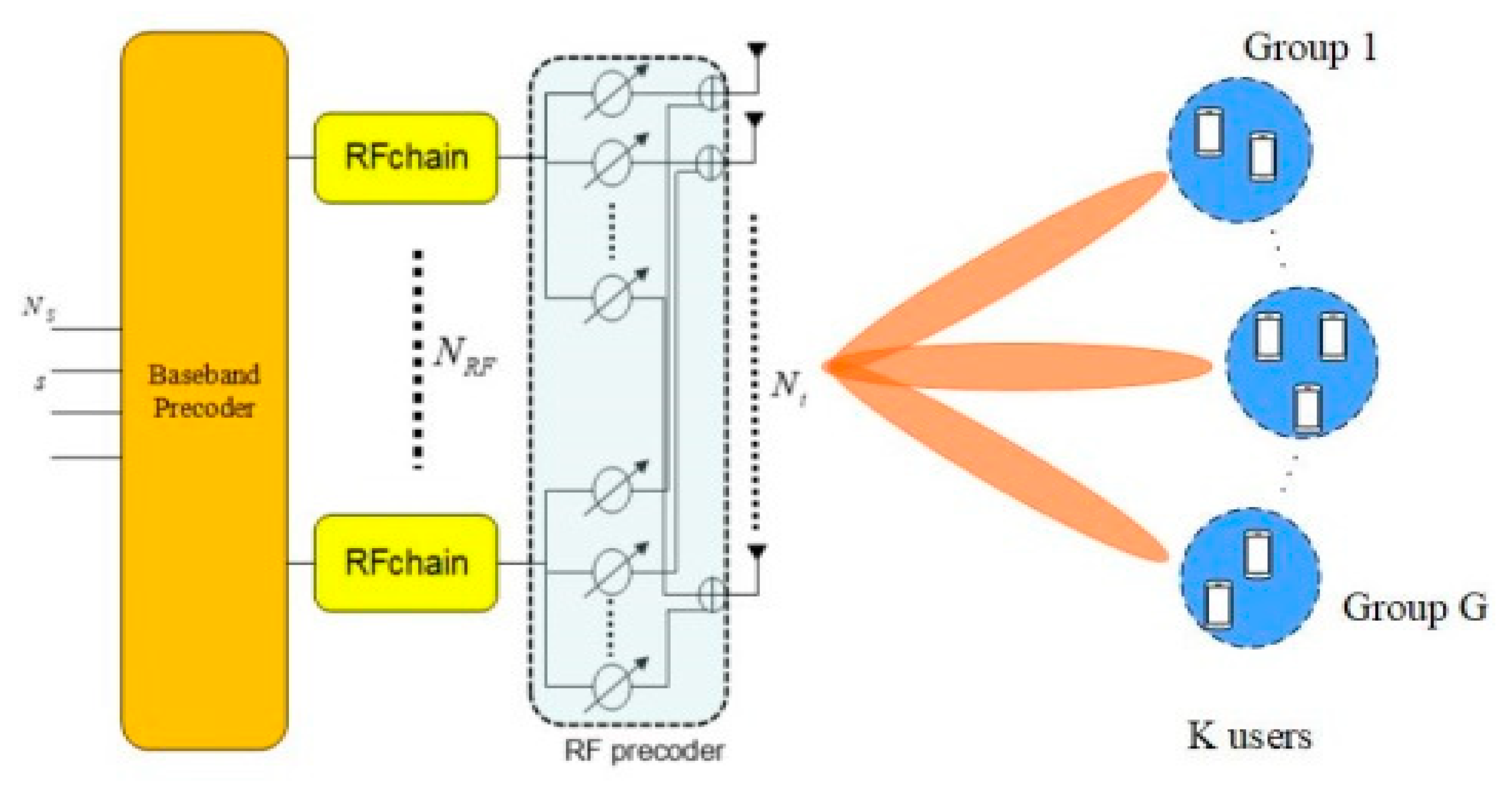
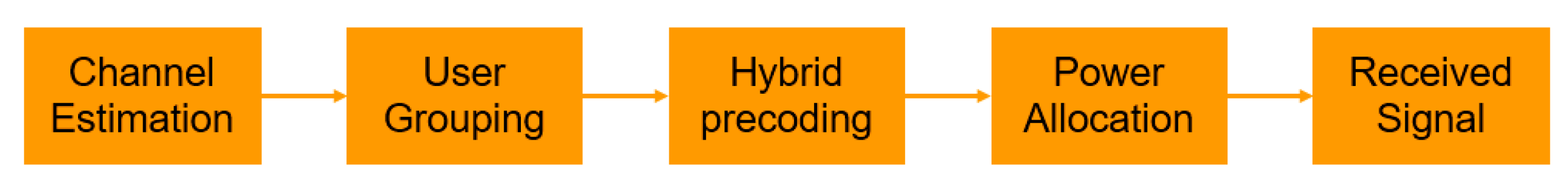
The remainder of the paper is organized as follows: Section 2 derives the system model and channel model based on mmWave mMIMO-NOMA; Section 3 investigates the impact of user grouping scheme, hybrid precoder scheme, and power allocation scheme on the system performance, respectively; Section 4 describes the simulation results and analyzes the simulation results; finally, Section 5 concludes the full paper.

2. System Model

In this section, we consider a downlink single-cell mmWave mMIMO-NOMA system, where the base station equips N t antennas and N R F RF chains to serve K single-antenna users through spatial multiplexing, such that N R F K , and we adopt a fully connected hybrid precoding architecture, as shown in Figure 1. In the conventional mmWave mMIMO system, the BS (Base Station) adopts the digital precoder where each antenna needs to be connected to a dedicated RF chain, therefore the number of RF chains equals the number of antennas, resulting in huge hardware overhead and energy losses. In contrast, the number of RF chains is much smaller than the number of antennas in the mmWave mMIMO-NOMA system and the hybrid precoder is used to eliminate the interference and enhance the antenna array gain, which is made up of a high-dimensional analog precoder and a low-dimensional digital precoder. In addition, for the fully connected structure, N R F RF chains are connected to N t antennas by finite-resolution phase shifters, where N t N R F phase shifters are required, and thus every RF chain can enjoy the full antenna array gain [17,18]. Generally, the fully connected structure obtains better performance gain and achieves higher spectral efficiency.
After the user signals pass through the hybrid precoder, the user signals can be transmitted on G beams simultaneously using the superposition coding, but the number of beams cannot exceed the number of RF chains. To take full advantage of the multiplexing gain, we assume that the number of beams equals the number of RF chains, i.e., G = N R F . Additionally, each beam can support a larger number of users by using NOMA technology, such that S g denotes the set of users located in the gth beam and the number of users in each set is more than one, i.e., | S g | 1 , the user cannot be located in different sets at the same time, i.e., | S i | | S j | = ϕ , i j , and the number of users for all sets is K, i.e., g = 1 G | S g | = K . Then, the received signal y g , m for g = 1 , , G , m = 1 , , | S g | of the mth users in the gth beam can be expressed as follows:
y g , m = h g , m H A g = 1 G m = 1 | S g | d g p g , m s g , m + n g , m = h g , m H A d g p g , m s g , m + h g , m H A d g ( j = 1 m 1 p g , j s g , j + j = m + 1 | S g | p g , j s g , j ) + h g , m H A i = 1 i g G j = 1 | S i | d i p i , j s i , j + n g , m
where h g , m is the channel vector of the mth user in the gth beam, s g , m is the transmitted signal of the mth user in the gth beam, and the signal satisfies E { | s g , m | 2 } = 1 , p g , m is the transmitted power of the mth user in the gth beam, n g , m is the noise subjecting to the complex Gaussian distribution, i.e., n g , m ~ C Ν ( 0 , σ n 2 ) . Furthermore, A is the analog precoder of size N t × N R F , d g is the digital precoding vector of the gth beam of size N R F × 1 , and the total power constraint is performed by normalizing the digital precoder d g , g = 1 , , G for the gth beam so that the digital precoder satisfies the constraint A d g 2 = 1 for g = 1 , 2 , , G .
Due to the sparse scattering nature of mmWave channels, the high free-space path loss of the mmWave channel leads to finite space selectivity or scattering. Therefore, we adopt the extended Saleh–Valenzuela channel model [19,20], where the channel is a sum of the contributions of L g , m paths. Accordingly, the channel of the mth users in the gth beams denoted as h g , m , g = 1 , , G , m = 1 , , | S g | , which can be written as follows:
h g , m = N t L g , m l = 1 L g , m α g , m ( l ) a ( θ g , m ( l ) ϕ g , m ( l ) )
where L g , m is the number of propagation paths for the mth users in the gth beams, α g , m ( l ) is the complex gain of the lth path for the mth user in the gth beam, θ g , m ( l ) ( ϕ g , m ( l ) ) denotes the azimuth(elevation) angle of departure of the lth path, and a ( θ g , m ( l ) ϕ g , m ( l ) ) denotes the normalized transmit array response vector. Additionally, for the uniform linear array used in this paper, the array response vector a ( θ ) is given by:
a U L A ( θ ) = 1 N t [ 1 , e j 2 π λ d sin ( θ ) , , e j ( N 1 ) 2 π λ d sin ( θ ) ] T
where λ is the signal wavelength, and the inter-element distance d = λ 2 . Notice that since the array response in the elevation domain is invariant, Equation (3) omits ϕ . Moreover, due to the channel is Time Division Duplexing (TDD), the channel state information (CSI) is symmetrically known to both the BS and users, we assume that the channel h g , m is perfectly known to both the BS and users.
Multiple users are supported in each beam by using superposition coding (SC) at the transmitter and successive interference cancellation (SIC) at the receiver to achieve higher spectral efficiency. Generally, for better performing SIC, we assume that the effective channel gains for the users in the gth beam are ordered as follows:
h g , 1 H A d g 2 h g , 2 H A d g 2 h g , | S g | H A d g 2 , g = 1 , G
After performing SIC, the mth user can ignore the interference of the jth(j > m) user in the gth beam. Hence, y g , m can be rewritten as:
y g , m = h g , m H A d g P g , m s g , m + h g , m H A d g j = 1 m 1 p g , j s g , j + h g , m H A i g j = 1 | S i | d i p i , j s i , j + n g , m
Accordingly, the SINR of the mth user in the gth beam can be expressed as follows:
γ g , m = h g , m H A d g 2 2 p g , m ξ g , m
where ξ g , m = h g , m H A d g 2 2 j = 1 m 1 p g , j + i g h g , m H A d i 2 2 j = 1 | S i | p i , j + σ n 2 . Hence, the achievable rate of the mth user in the mth beam is formulated as:
R g , m = log 2 ( 1 + γ g , m )
the achievable sum rate can be obtained as follows:
R s u m = g = 1 G m = 1 | S g | R g , m
the achievable sum rate can be improved by the design of user grouping, analog precoder A, digital precoder for the gth user { d g } g = 1 G , and power allocation p g , m , but it is difficult to jointly optimize these schemes simultaneously to obtain the optimal solution, so we separately design these three schemes in the next section.
Figure 2 shows the framework of the system model. Due to the model of the channel is TDD, hence the CSI is known to both the BS and the users. Then, the BS performs the user grouping algorithm according to the channel of users. Then, according to the result of user grouping, the BS designs the analog precoder and the digital precoder, respectively. Then, the BS optimizes the power allocation for each user. Finally, the users receive the transmission signals and decode the desired signal by using SIC.

3. Performance Optimization

Due to the number of supported users being much larger than the number of RF chains in the mmWave mMIMO-NOMA system, i.e., K > N R F , we will first assign users to G groups, then the objective function is obtained to optimize the hybrid precoder and power allocation.

3.1. User Grouping and Problem Formulation

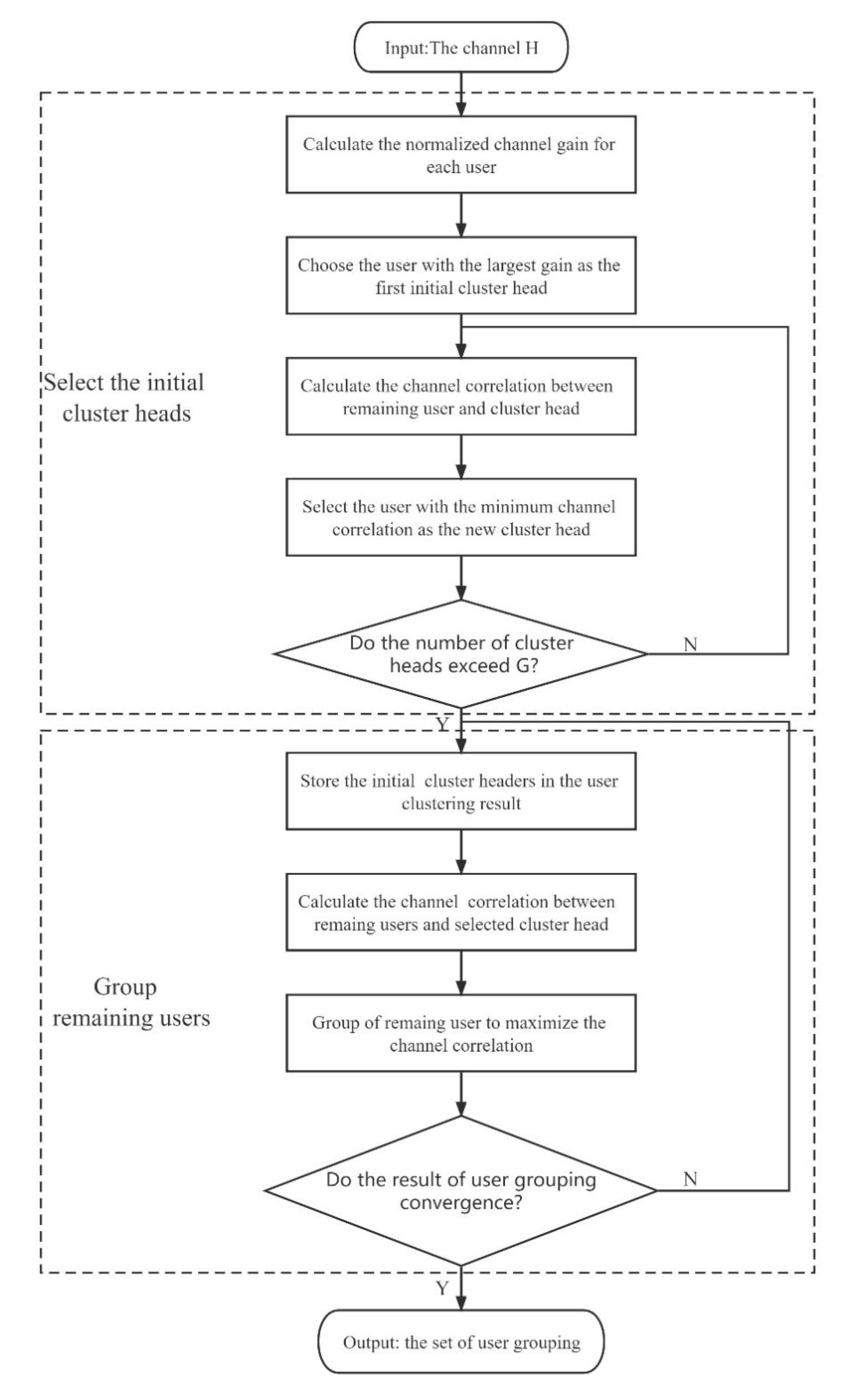
3.1.1. User Grouping

In the massive MIMO-NOMA system, the users in the same group will enjoy the same hybrid precoder to enhance their beam gain and eliminate the interference from other groups, different beams delegates different groups. Therefore, the intuitive algorithm is proposed to assign users to different groups, the channels of users in the same beam are highly correlated to allow for high beam gain, and the channels of users in different beams are weakly correlated to suppress the interference. The normalized channel correlation between user i and user j is expressed as C o r r i , j = | h i H h j | / ( h i 2 h j 2 ) . The proposed user grouping algorithm starts by selecting the initial cluster head for each beam, and the initial cluster heads are selected by satisfying the adaptive threshold δ 1 and minimizing the normalized channel correlation with other selected cluster heads. The remaining users are then iteratively assigned to the same beam as the cluster head to suppress the intra-beam interference, where the channel correlation between users and cluster head is high.
The pseudocode for the proposed user grouping algorithm is given in Algorithm 1. Compared with the K-means algorithm for randomly selecting initial cluster heads, we first select the initial cluster head (in step 10) for each beam by satisfying the adaptive threshold δ 1 and minimizing the normalized channel correlation among the selected cluster heads. Hence, the cluster heads are selected as a set, i.e., Ω = { Ω 1 , , Ω G } . after steps 8–14 are finished. Then, the remaining users are iteratively assigned to different groups by minimizing the normalized channel correlation until the user grouping results are not changed through steps 17–25. The final group is denoted as Γ g , g = 1 , G .
Algorithm 1: User clustering algorithm.
Inputs: number of users K, number of beams G, channel vector h k , k [ 1 , K ] , adaptive threshold δ 1 , δ 2
Initialization: Ω = 0 G
Output: the set of users after clustering { Γ 1 , , Γ G }
1: Channel gain of the user h = [ h 1 2 , h K 2 ] , where a k = h k 2
2: User channel normalization h ¯ k = h k / h k , k = 1 , 2 , K
3: [ ~ , O ] = s o r t ( h , d e s c e n d )
4: Ω ( 1 ) = O ( 1 )
5: O ( 1 ) = [ ]
6: Φ = O
7: g = 2
8: while g <= G do
9:  v = | h ¯ i H h ¯ j | , i Φ , j Ω
10:  [ ~ , O ] = min ( f i n d ( v < δ 1 ) )
11:  Ω ( g ) = Φ ( O ( 1 ) )
12:  Φ ( f i n d ( Φ = = Ω ( g ) ) ) = [ ]
13:  g = g + 1
14: end while
15: Ω = { Ω 1 , , Ω G }
16: t = 1
17: while do  Ω g t Ω g t 1
18: Set { Γ g } g = 1 G = { Ω g t } g = 1 G
19: for do  k Κ / Ω g t
20:   g * = arg max 1 g G C o r r g , Ω g t
21:   Γ g * = Γ g * k
22: end for
23:  t = t + 1
24: Update Ω g t , g = 1 , G
25: end while
We summarize the user grouping algorithm, and the algorithm flow is presented in Figure 3.

3.1.2. Problem Formulation

After obtaining the final set of user grouping { Γ 1 , , Γ G } , we need to solve the hybrid precoder and the power allocation problem to maximize the achievable sum rate, and the objective function is formulated as follows:
max A , d g , p g , m g = 1 G m = 1 | S g | R g , m s . t . C 1 : p g , m 0 , g , m C 2 : R g , m R g , m min , g , m C 3 : g = 1 G m = 1 | S g | p g , m P max C 4 : m = 1 | S g | p g , m P g m a s k , g G C 5 : | [ A ] i , j | , 1 i N , 1 j N R F C 6 : A d g 2 = 1 , g G
where the constraint C 1 guarantees that the transmit power for each user is positive. The constraint C 2 denotes the predefined minimal rate constraint that the mth user in the gth beam required. The constraint C 3 signifies the total power constraint that the total transmittted power of BS cannot exceed P max . The constraint C 4 denotes the group power constraint that the total power of users in the gth beam cannot exceed P g m a s k . Here, C 5 is the constant-modulus constraint for the analog precoder. C 6 denotes the normalized power constraint for the hybrid precoder. It is challengable to jointly optimize all variables in Equation (9), and due to the total power constraint and the constant-modulus constraint of analog precoder, the objective optimization problem is nonconvex. Accordingly, Equation (9) is difficult to solve jointly and obtain the globally optimum solution, and we consider addressing the optimization problem by solving the hybrid precoder and the power allocation separately.

3.2. Hybrid Precoder Solution

After performing user grouping, the users in the same beam are highly correlated and those users who are located in different beams have low channel correlation. To maximize Equation (9) for each user, we need to consider Equations (6) and (7), we can know that the maximization of Equation (9) actually is equal to maximizing the SINR of the user, thus we need to consider how to reduce the inter-beam interference, i.e., i g h g , m H A d i 2 2 j = 1 | S i | p i , j , and enhance the desired signal of the user, i.e., h g , m H A d g 2 2 p g , m . Therefore, we use a two-stage hybrid precoding design scheme to maximize SINR for each user. To achieve full potentials of mmWave mMIMO-NOMA systems while reducing the hardware constraints, we adopt the low-cost phase shifters to link the N R F chains with N t antennas for adjusting phase-only response. Due to the constant-modulus constraint of analog precoder, the subset of the feasible solution is nonconvex, we consider adopting the two-stage hybrid precoder scheme, where the core idea is to design the analog precoder and the digital precoder separately. The pseudocode for the proposed two-stage hybrid precoder algorithm is shown as Algorithm 2.
Algorithm 2 Two-Stage Hybrid Precoder.
Inputs: Number of antennas N t , Number of users K, number of RF chains N R F , channel matrix H = [ h 1 , , h K ] , the optimized user grouping { Γ 1 , , Γ G }
Initialization: A = 0 N t × N R F , D = 0 N R F × K , number of quantization bits B.
Output: A
First stage: Single-user analog precoding design
1: Λ = 1 N t { e j 2 π n 2 B } , n = 0 , 1 , , 2 B 1
2: for g = 1 to N R F do
3:  H = H ( : , Γ ( g , 1 ) )
4:  Θ = a n g l e ( H )
5: for n = 1 to N t do
6:   [ ~ , i ] = min | Θ ( n ) Λ |
7:   θ ( n ) = Λ ( i )
8: end for
9:  A ( : , g ) by calculating (12)
10: end for
Second Stage: multiuser digital precoding design
1: H ¯ = H A
2: H ˜ = H ¯ ( : , Γ ( : , 1 ) )
3: D ˜ = H ˜ H ( H ˜ H ˜ H ) 1
4: according to (13), we get the normalized D ˜
5: D ( : , Γ ( : , 1 ) ) = D ˜
6: for g = 1 to N R F do
7: O = n o n z e r o s ( Γ ( g , : ) )
8: for n = 2 to l e n g t h ( O ) do
9:   D ( : , O ( : , n ) ) = D ˜ ( : , O ( : , 1 ) )
10: end for
11: end for

3.2.1. Analog Precoding

For the analog precoder, we aim to enhance the desired signal for each user to improve the SINR of the user, and we can increase the norm of the desired signal of the user by aligning the phase of H and the analog precoder, while we can also utilize the huge multiplexing gain provided by the massive antenna array. The pseudocode for the analog precoder is given in the first stage of Algorithm 2. Due to the limitation of the actual phase shifter, we apply a B-bit quantized phase shifter, with the non-zero elements of the analog precoder given by:
Λ = 1 N t { e j 2 π n 2 B } , n = 0 , 1 , , 2 B 1
Then, we utilize the channel of cluster head from the optimized user grouping, i.e., H ˜ = H ¯ ( : , Γ ( : , 1 ) ) , and step 4 extracts the phase of cluster head in the gth beam. The analog precoder is designed by aligning the phase of the channel through step 6 to step 9, hence the element of the analog precoder can be determined by minimizing the angle between the channel of cluster head and the element of Λ , and the index of the minimum angle is written as follows:
i = arg min i { 0 , 1 , 2 n 1 } | a n g l e ( H ˜ ) 2 π i 2 B |
After getting the phase set θ through steps 6–9, we can obtain the element of the gth column in the analog precoder by calculating the following expression:
a g = 1 N e j 2 π θ 2 B
After obtaining the analog precoder, the digital precoder will be designed by eliminating the inter-beam interference to maximize the achievable sum-rate in the second stage.

3.2.2. Digital Precoding

For the digital precoder, we aim to eliminate the interference from other beams to improve the SINR of the user, we can obtain the equivalent channel for each user after obtaining the analog precoder, then the digital precoder design is actually the inter-beam interference elimination problem of the traditional MIMO-NOMA system, therefore we consider a low complexity zero-forcing precoding based on the users with the strongest effective channels in each beam. The Pseudocode of the digital precoder is presented in the second stage of Algorithm 2. We first obtain the equivalent channel matrix, i.e., H ¯ = H A in step 1, and assume that the m g th user in the gth beam has the highest equivalent channel gain, i.e., H ˜ = [ h ¯ m 1 , h ¯ m 2 , h ¯ m G ] , Then, we utilize the zero-forcing to cancel the inter-beam interference through step 3, and the digital precoder is calculated as D ˜ = H ˜ H ( H ˜ H ˜ H ) 1 . Subsequently, the normalized digital precoder is written as:
d g = d ˜ g A d ˜ g 2
Due to the users in the same beam enjoying the same digital precoder, the digital precoder for each beam D = [ d 1 , , d g ] is designed through step 6 to step 13 after N R F iterations. Notice that there are G = N R F beams.
After designing the hybrid precoder, the order of effective channel gains for each user no longer changes. Therefore, in order to facilitate the implementation of SIC, the users in each group are resorted such that h ¯ g , 1 H d g 2 h ¯ g , 2 H d g 2 h ¯ g , | S g | H d g 2 for g = 1 , 2 , , G .

3.3. Power Allocation Solution

After performing user grouping and hybrid precoding, we propose a global power allocation scheme under the minimum rate constraint for the spectral efficiency maximization problems. Additionally, the objective function can be transformed into the following function:
max p g , m g = 1 G m = 1 | S g | R g , m ( p g , m ) s . t . C 1 : p g , m 0 , g , m C 2 : R g , m R g , m min , g , m C 3 : g = 1 G m = 1 | S g | R g , m P max C 4 : m = 1 | S g | R g , m P g m a s k , g G
where R g , m is the achievable rate of the mth user in the gth beam and the constraint C 1 denotes that the power of each user is positive. The constraint C 2 is the minimum rate constraint which each user needs to achieve, R g , m min is the minimum rate of the mth user in the gth beam. The constraint C 3 is the total transmitted power constraint, which P max is the maximum total power that can be transmitted by the base station, and the constraint C 4 is the power constraint of each beam, where P g m a s k is the maximum power constraint of each beam.
We define q g = m = 1 | S g | p g , m as the sum power consumption of the gth cluster, then the objective function can be equivalently transformed into a joint inter- and intra-cluster power allocation problem:
max p g , m , q g , m g = 1 G m = 1 | S g | R g , m ( p g , m ) s . t . C 1 : p g , m 0 , g , m C 2 : R g , m R g , m min , g , m C 3 : g = 1 G q g P max C 4 : 0 q g P g m a s k , g G
In the NOMA system, the feasible set of Equation (15) is the intersection of closed-boxes along with the affine cluster power constraint [15], i.e., q g [ Q g min , P g m a s k ] , g G , the lower bound constraint is given by:
Q g min = m = 1 | S g | β m ( i = 1 h ˜ g , i > h ˜ g , m | S g | ( 1 + β i ) + 1 h ˜ g , m + i = 1 h ˜ g , i > h ˜ g , m | S g | j = 1 h ˜ g , i < h ˜ g , j < h ˜ g , m | S g | ( 1 + β j ) h ˜ g , i )
where β m = 2 ( R m min ) 1 , m | S g | , where h ˜ g , m denotes that the effective channel of the mth user in the gth beam after hybrid precoding, i.e., h ˜ g , m = h g , m * A * d g . If q g [ Q g min , P g m a s k ] , g G , it means that the users in the gth beam can satisfy the minimum rate constraint.
According to the Appendix B in [21], we can know that the optimal solution of power allocation in the sum rate maximization problem is that users in the same cluster with low decoding order are allocated power only to maintain their minimum rate, allocating the remaining power to the cluster head users. The optimal intra-cluster power is expressed as follows:
p g , m * = ( β m i = 1 h ˜ g , i < h ˜ g , m | S g | ( 1 β i ) ) q g + c g , m , m Φ g
p g , Φ g * = ( 1 i = 1 h ˜ g , i < h ˜ g , Φ g | S g | β m j = 1 h ˜ g , j < h ˜ g , i | S g | ( 1 β j ) ) q g m = 1 h ˜ g , m < h ˜ g , Φ g | S g | c g , m
where p g , m * is the optimal power of the mth user in the gth beam and p g , Φ g * is the optimal power of the cluster head in the gth beam, β m = 2 ( R m min ) 1 2 ( R m min ) , m | S g | ,   c g , m = β m ( 1 h ˜ g , m i = 1 h ˜ g , i < h ˜ g , m | S g | j = 1 h ˜ g , i < h ˜ g , j < h ˜ g , m | S g | ( 1 β j ) β i h ˜ g , i ) , g G , m | S g | .
There is a competition among the cluster heads to get the remaining power after obtaining the optimal intra-cluster power allocation. According to Equation (18), we define the power of the cluster head users Φ g as a function of q g which is given by:
p g , Φ g * = α g q g c g , g G
where α g = ( 1 m = 1 h ˜ g , m < h ˜ g , Φ g | S g | β m m = 1 h ˜ g , m < h ˜ g , Φ g | S g | ( 1 β m ) ) , and c g = m = 1 h ˜ g , m < h ˜ g , Φ g | S g | c g , m are non-negative constraints, so according to Equation (19), the optimal value of Equation (17) for the given q g in the gth beam can be reformulated in closed form as:
R g ( q g ) = m = 1 | S g | R g , m ( p g , m * ) = m = 1 m Φ g | S g | R g , m min + R g , Φ g ( q g ) = m = 1 m Φ g | S g | R g , m min + log 2 ( 1 + ( α g q g c g ) h ˜ g , Φ g )
Due to R g , m min being a constant, the power of gth beam is determined when the optimal power of gth beam is determined, so we can equivalently transform Equation (15) to the following inter-cluster power allocation problem:
max q g = 1 G log 2 ( 1 + ( α g q g c g ) h ˜ g , Φ g ) s . t . C 1 : g = 1 G q g = P max C 2 : q g [ Q g min , P g m a s k ] , g G
where the constraint C 1 is the total power constraint and the constraint C 2 denotes the required power for each beam to ensure that each cluster is able to satisfy the minimum constraint. For simplicity, let q ˜ = [ q ˜ g ] , g G , and q ˜ g = q g c g α g . Then, Equation (21) is equivalently transformed to the following convex problem as:
max q ˜ g = 1 G log 2 ( 1 + q ˜ g h g ) s . t . C 1 : g = 1 G q ˜ = P ˜ max , q ˜ g [ Q ˜ g min , P ˜ g m a s k ] , g G
where h g = α g h ˜ g , Φ g , P ˜ max = P max c g α g , Q ˜ g min = Q g min c g α g , P ˜ g m a s k = P g m a s k c g α g . The equivalent problem Equation (22) can be viewed as a sum of G virtual OMA users, each cluster can be viewed as an OMA user. Next, our goal is to solve the equivalent problem Equation (22) by using the Lagrange duality of Equation (22). The generalized Lagrange function of Equation (22) is expressed as follows:
L ( q , v ) = g = 1 G log 2 ( 1 + q ˜ g h g ) + v ( P ˜ max g = 1 G q ˜ g )
where v is the Lagrangian multiplier for the total power constraint and q ˜ g [ Q ˜ g min , P ˜ g m a s k ] , g G , we can further obtain the upper bound of the Lagrange function:
g ( v ) = sup q ˜ Ρ ( L ( q ˜ , v ) ) = sup q ˜ Ρ { g = 1 G log 2 ( 1 + q ˜ g h g ) + v ( P ˜ max g = 1 G q ˜ g ) } ,
where P is the set of feasible solutions to Equation (22) and the Lagrange dual problem is established as follows:
min v g ( v ) , s . t . v R
The KKT conditions are listed as follows:
C 1 : q ˜ g [ Q ˜ g min , P ˜ g m a s k ] , g G C 2 : P ˜ max g = 1 G q ˜ g * = 0 C 3 : q ˜ L ( q ˜ * , v * ) = 0
By solving for C 3 , the optimal inter-cluster power q ˜ g * can be obtained as:
q ˜ g * = { 1 ( ln 2 ) v * 1 h g , ( 1 ( ln 2 ) v * 1 h g [ Q ˜ g min , P ˜ g m a s k ] ) ; 0 , o t h e r w i s e .
We then use the bisection search method to find v * ; the pseudo-code of bisection search method is presented in Algorithm 3. We first initialize tolerance ε , lower bound v l and upper bound v h . The lower bound v l needs to satisfy g G max { Q ˜ g min , min { ( 1 ( ln 2 ) v * 1 h g ) , P ˜ g m a s k } } > P ˜ max , and v h the upper bound needs to satisfy g G max { Q ˜ g min , min { ( 1 ( ln 2 ) v * 1 h g ) , P ˜ g m a s k } } < P ˜ max . After finding q ˜ g * , we can get the value of q g * by calculating q g * = ( q ˜ g * + c g α g ) , g G , where q g * is the corresponding inter-cluster power for each beam. Finally, according to Equations (17) and (18), we can obtain the optimal power for each user.
Algorithm 3: Bisection search method.
1: Initialize the tolerance ε , the lower bound v l , the upper bound v h and the maximum number of iterations L
2: for l = 1:L do
3: Set v m = v l + v h 2
4: if g G max { Q ˜ g min , min { ( 1 ( ln 2 ) v * 1 h g ) , P ˜ g m a s k } } < P ˜ max then
5:  Set v h = v m
6: else
7: Set v h = v m
8:  end if
9:  if then P ˜ max g G max { Q ˜ g min , min { ( 1 ( ln 2 ) v * 1 h g ) , P ˜ g m a s k } } P ˜ max ε
10: break
11: end if
12: end for

4. Simulation Results

In this section, we demonstrate the superiority of the proposed algorithm by analyzing the simulation results with different parameters and compare with K means algorithm [10], CHS algorithm [11], FPA algorithm, and OMA system. We assume that N t = 64 antennas, N R F = 4 chains, the resolution of PSs is B = 4 bits, K users, K users are divided into G = N R F clusters. The channel is generated based on Equation (2) with L g , m = 3 , where L g , m denote that the number of propagation paths, and we assume that L g , m consists of one line of sight component (LOS) where the contribution follows α g , m ( 1 ) ~ C N ( 0 , 1 ) , and two non-line of sight (NLOS) component where the contribution follows α g , m ( l ) ~ C N ( 0 , 10 1 ) , 2 l L g , m . The azimuth (elevation) AOD ϕ g , m ( l ) , θ g , m ( l ) follows a uniform distribution ( π , π ) , where 1 l L g , m . The signal-to-noise ratio (SNR) we defined as P t σ v 2 , and the total transmitted power P t = 30 mW. The parameters of the channel model are set in Table 1. MATLAB R2018a is used for simulation, and the simulation results are based on 3000 random channel samples.

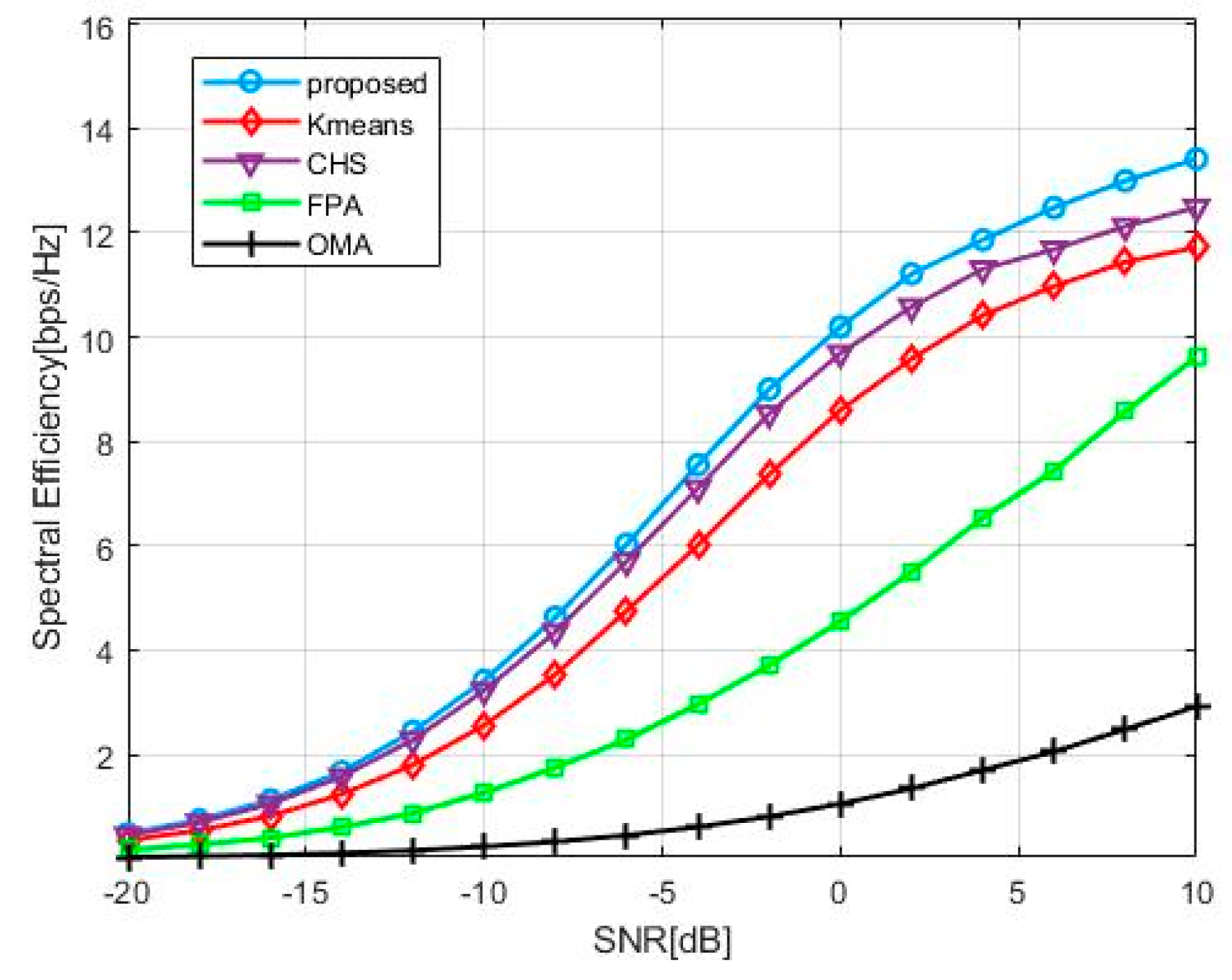
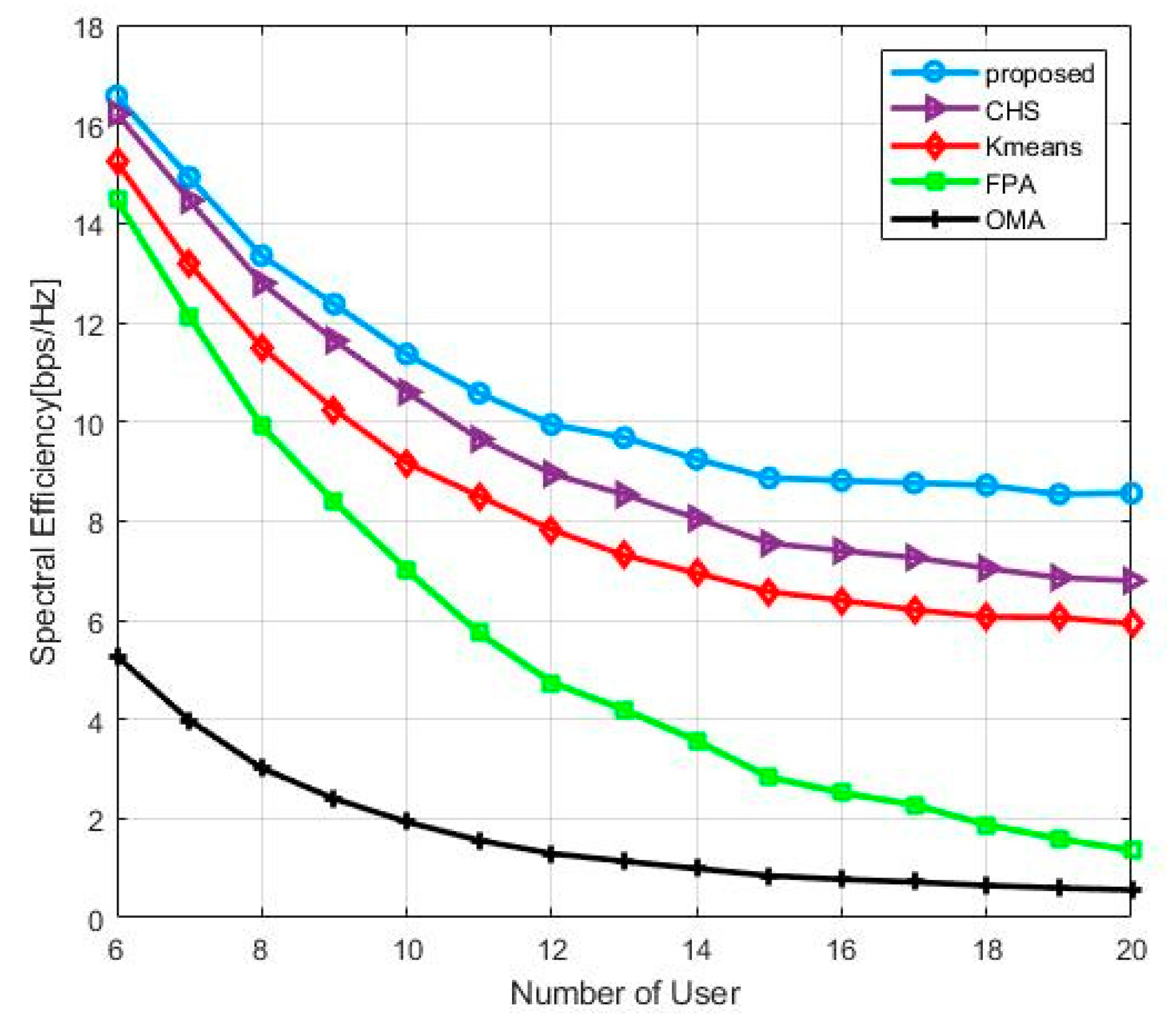
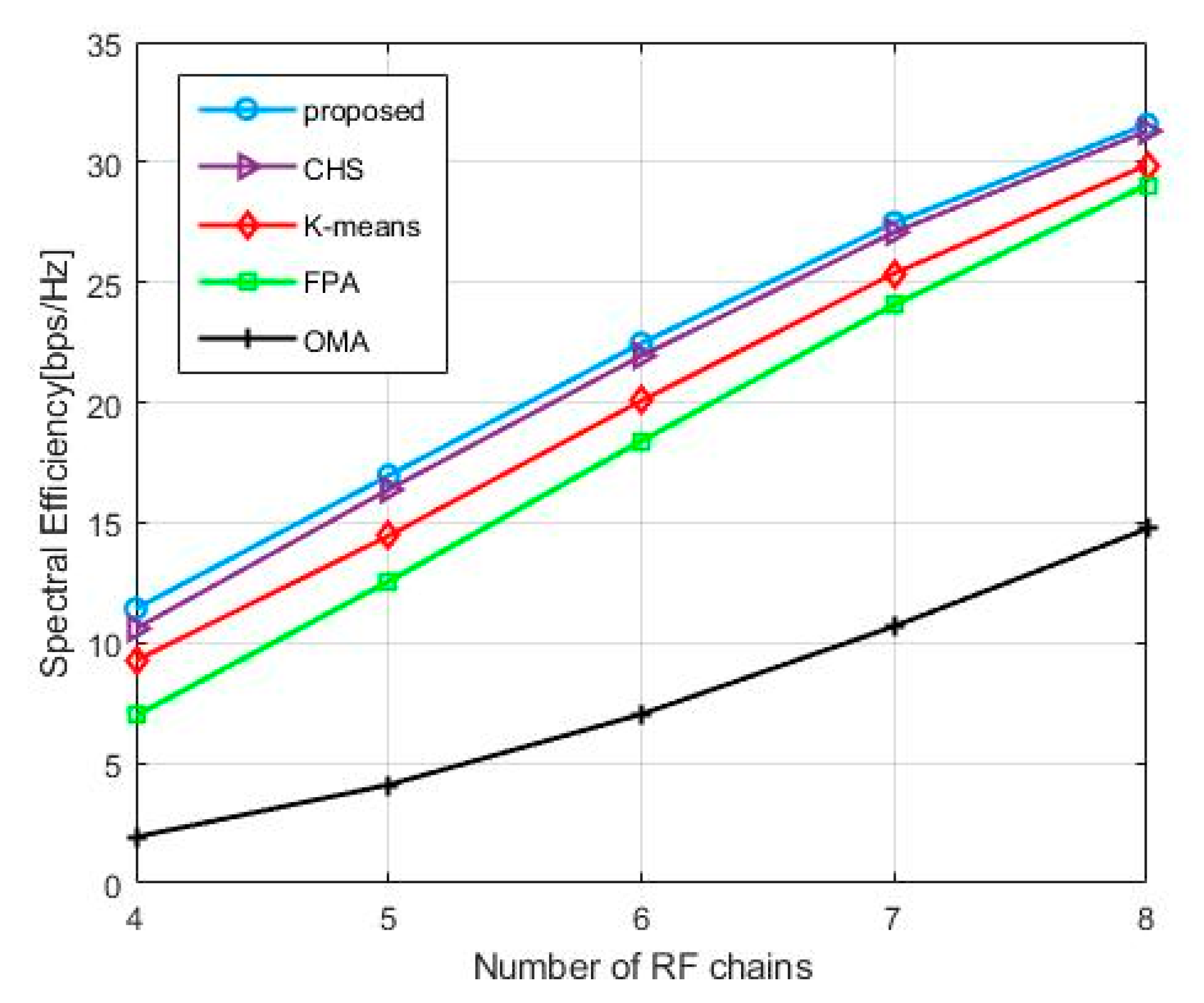
4.1. Comparison and Analysis of Spectral Efficiency Performance

Figure 4 shows the spectral efficiency of different algorithms with the increasing SNR in the mmWave mMIMO-NOMA system, where the number of users K = 8 . Since the number of users is larger than the number of RF chains, and the OMA system can only serve N R F users in the same time-frequency domain compared with the NOMA system, it is obvious that the NOMA scheme performs better than the OMA scheme. The proposed power allocation algorithm is able to allocate the optimal power to each user precisely under the minimum rate constraint and the FPA algorithm allocates the fixed power for each user; therefore, we can see that the FPA algorithm performs worse than the proposed scheme. As for the K-means algorithm and the CHS algorithm used in user grouping, the K means algorithm randomly choose the initial cluster head, resulting in the user grouping result falling into the locally optimal solution, and the CHS algorithm selects the initial cluster head for each group, but the CHS algorithm does not divide the users to the group iteratively. As a consequence, the user grouping results are not accurate enough. The proposed algorithm not only selects the initial cluster head, but also obtains the optimal user grouping result by iteratively performing user grouping; therefore, the proposed algorithm can achieve better spectral efficiency.
Figure 5 shows the spectral efficiency of the proposed algorithm with the number of users, where SNR = 10 and the number of users interval is [6, 20]. Apparently, as the number of users increases, the inter-user interference will increase and the allocated power for each user will decrease; therefore, the spectral efficiency shows a decreasing trend. Obviously, the OMA system performs worst compared with the NOMA system because the OMA system can only serve N R F users in the same time-frequency domain. As the number of users increases, the spectral efficiency of the FPA scheme decreases sharply due to the decrease in the allocated power of the cluster head. Because the proposed user grouping algorithm not only considers the effect of the selected initial cluster head on the user grouping result, but also iteratively divide the users into different clusters to obtain the global user grouping result, the proposed user grouping algorithm performs better than the CHS algorithm and the K means algorithm. Additionally, we can see that as the number of users increases, the curve of the CHS algorithm is farther to the curve of the proposed algorithm, closer to the curve of the K-means algorithm, because as the number of users increases, the diversity of user channels makes it difficult to accurately select the cluster heads.
Figure 6 shows the spectral efficiency of the proposed algorithm with the number of RF chains, where SNR = 10, the number of the user k = 10 , and the number of RF chains interval is [4, 8]. Clearly, as the number of RF chains increases, the number of beams also increases at the same time-frequency domain, therefore the spectral efficiency shows a decreasing trend. Obviously, the OMA system performs worst compared with the NOMA system due to the limitation of the system. As the number of RF chains increases, the performance gap between algorithms is decreasing. When the number of RF chains is four, the proposed algorithm outperforms the CHS algorithm, the K-means algorithm, and the FPA algorithm by 7.9%, 18.9% and 38.9%, respectively. When the number of RF chains is eight, the proposed algorithm outperforms the CHS algorithm, the K-means algorithm, and the FPA algorithm by 0.9%, 5.3% and 8.0%, respectively. When the number of RF chains is equal to the number of users, the system is actually a MIMO-OMA system, and the hardware overhead increases dramatically due to the increase in the number of RF chains; therefore, we only study the case where the number of RF chains is less than the number of users, and we can see that the proposed scheme performs best compared to other schemes.

4.2. Computational Complexity

Next, we analyze the computational complexity of the proposed algorithm, CHS algorithm, and K-means algorithm, which is used in the user grouping part. For the CHS algorithm, the computational complexity is O (GK2). For the K-means algorithm, the computational complexity is O (K2 + GK). As for the proposed algorithm, the algorithm not only selects the initial cluster heads but also performs the proposed algorithm iteratively. Hence, the user grouping result of the proposed algorithm is more accurate compared with the CHS algorithm and the performance of the proposed algorithm is better than other algorithms. However, the computational complexity of the proposed algorithm is much higher, and the computational complexity is O (K2Nt + K2 + GK).

5. Conclusions and Future Work

5.1. Conclusions

In this paper, we apply NOMA to mmWave mMIMO systems to improve spectral efficiency. Accordingly, the user grouping and the hybrid precoder scheme are designed to eliminate the inter-user interference and the power allocation scheme is designed to further improve the spectral efficiency. We first perform the user grouping algorithm to ensure the channel of users in the same group are highly correlated and the channel of users in different groups are weakly correlated. Since the precoder and the combiner are symmetric in the system, we only need to focus on the design of the precoder, the two-stage hybrid precoder is designed to eliminate the inter-beam interference, the analog precoder is designed based on channel alignment to maximize the array gain and the zero-forcing algorithm is used to design the digital precoder. Finally, we convert the non-convex spectral efficiency optimization problem into a convex inter-cluster power allocation problem, and the optimal power closed-form solution is obtained by solving the KKT condition. Simulation results show that the proposed algorithm can achieve higher spectral efficiency compared with OMA, FPA, K means, and CHS algorithms in terms of SNR and the number of users.

5.2. Future Work

The proposed scheme can be used in the downlink mmWave communication system for the 6G network, and the proposed user grouping scheme facilitates the elimination of inter-user interference and resource allocation, thus the future application scenarios may be the Internet of Things (IoT) communication in indoor scenarios and communication between user and base station in the cell. The drawback of our proposed approach is in the way that the proposed user grouping scheme, hybrid precoder, and power allocation scheme are designed, such that the solutions of the user grouping result, hybrid precoder and power allocation will influence each other, respectively; thus, the solution we obtain is only a static local optimal solution. Therefore, the future research directions are how to jointly optimize each variable to achieve higher spectral efficiency.

Author Contributions

Conceptualization, Z.Z. and Y.Z.; methodology, Z.Z., H.D. and F.X.; software, Z.Z., W.Z. and Y.Z.; validation, Z.Z, G.L. and W.Z.; formal analysis, Z.Z. and H.D.; investigation, Z.Z., W.Z. and Y.Z.; resources, Z.Z., W.Z. and G.L; data curation, Z.Z.; writing—original draft preparation, Z.Z. and W.Z.; writing—review and editing, Z.Z., H.D. and W.Z.; All authors have read and agreed to the published version of the manuscript.

Funding

This research received no external funding.

Institutional Review Board Statement

Not applicable.

Informed Consent Statement

Not applicable.

Data Availability Statement

Not applicable.

Conflicts of Interest

The authors declares no conflict of interest.

References

  1. Chowdhury, M.Z.; Shahjalal, M.; Ahmed, S.; Jang, Y.M. 6G Wireless Communication Systems: Applications, Requirements, Technologies, Challenges, and Research Directions. IEEE Open J. Commun. Soc. 2020, 1, 957–975. [Google Scholar] [CrossRef]
  2. Solaiman, S.; Nassef, L.; Fadel, E. User Clustering and Optimized Power Allocation for D2D Communications at mmWave Underlaying MIMO-NOMA Cellular Networks. IEEE Access 2021, 9, 57726–57742. [Google Scholar] [CrossRef]
  3. Hu, X.; Zhong, C.; Chen, X.; Xu, W.; Zhang, Z. Cluster Grouping and Power Control For Angle-Domain MmWave MIMO NOMA Systems. IEEE J. Sel. Top. Signal Process. 2019, 13, 1167–1180. [Google Scholar] [CrossRef]
  4. Shahjalal, M.; Hasan, M.K.; Islam, M.M.; Chowdhury, M.Z.; Jang, Y.M. A Two-Stage Power Allocation-Based NOMA Architecture for Optical Camera Communication. IEEE Syst. J. 2021, 15, 4421–4430. [Google Scholar] [CrossRef]
  5. Uwaechia, A.N.; Mahyuddin, N.M. A Comprehensive Survey on Millimeter Wave Communications for Fifth-Generation Wireless Networks: Feasibility and Challenges. IEEE Access 2020, 8, 62367–62414. [Google Scholar] [CrossRef]
  6. Zhao, N.; Wang, W.; Wang, J.; Chen, Y.; Lin, Y.; Ding, Z.; Beaulieu, N.C. Joint Beamforming and Jamming Optimization for Secure Transmission in MISO-NOMA Networks. IEEE Trans. Commun. 2019, 67, 2294–2305. [Google Scholar] [CrossRef] [Green Version]
  7. Zhu, L.; Zhang, J.; Xiao, Z.; Cao, X.; Wu, D.O.; Xia, X.-G. Joint Tx-Rx Beamforming and Power Allocation for 5G Millimeter-Wave Non-Orthogonal Multiple Access Networks. IEEE Trans. Commun. 2019, 67, 5114–5125. [Google Scholar] [CrossRef] [Green Version]
  8. Wang, B.; Dai, L.; Wang, Z.; Ge, N.; Zhou, S. Spectrum and Energy-Efficient Beamspace MIMO-NOMA for Millimeter-Wave Communications Using Lens Antenna Array. IEEE J. Sel. Areas Commun. 2017, 35, 2370–2382. [Google Scholar] [CrossRef] [Green Version]
  9. Zhu, L.; Zhang, J.; Xiao, Z.; Cao, X.; Wu, D.O.; Xia, X.-G. Millimeter-Wave NOMA With User Grouping, Power Allocation and Hybrid Beamforming. IEEE Trans. Wirel. Commun. 2019, 18, 5065–5079. [Google Scholar] [CrossRef] [Green Version]
  10. Xiong, C.; Hua, Z.; Lv, K.; Li, X. An Improved K-means Text Clustering Algorithm by Optimizing Initial Cluster Centers. In Proceedings of the 2016 7th International Conference on Cloud Computing and Big Data (CCBD), Macau, China, 16–18 November 2016. [Google Scholar]
  11. Dai, L.; Wang, B.; Peng, M.; Chen, S. Hybrid Precoding-Based Millimeter-Wave Massive MIMO-NOMA With Simultaneous Wireless Information and Power Transfer. IEEE J. Sel. Areas Commun. 2019, 37, 131–141. [Google Scholar] [CrossRef] [Green Version]
  12. Hao, W.; Zeng, M.; Chu, Z.; Yang, S. Energy-Efficient Power Allocation in Millimeter Wave Massive MIMO With Non-Orthogonal Multiple Access. IEEE Wirel. Commun. Lett. 2017, 6, 782–785. [Google Scholar] [CrossRef] [Green Version]
  13. Zhu, J.; Li, Q.; Liu, Z.; Chen, H.; Vincent Poor, H. Enhanced User Grouping and Power Allocation for Hybrid mmWave MIMO-NOMA systems. IEEE Trans. Wirel. Commun. 2021, 1. [Google Scholar] [CrossRef]
  14. Zhu, J.; Wang, J.; Huang, Y.; He, S.; You, X.; Yang, L. On Optimal Power Allocation for Downlink Non-Orthogonal Multiple Access Systems. IEEE J. Sel. Areas Commun. 2017, 35, 2744–2757. [Google Scholar] [CrossRef] [Green Version]
  15. Rezvani, S.; Jorswieck, E.A.; Joda, R.; Yanikomeroglu, H. Optimal Power Allocation in Downlink Multicarrier NOMA Systems: Theory and Fast Algorithms. IEEE J. Sel. Areas Commun. 2022, 1. [Google Scholar] [CrossRef]
  16. Xiao, Z.; Zhu, L.; Choi, J.; Xia, P.; Xia, X.-G. Joint Power Allocation and Beamforming for Non-Orthogonal Multiple Access (NOMA) in 5G Millimeter Wave Communications. IEEE Trans. Wirel. Commun. 2018, 17, 2961–2974. [Google Scholar] [CrossRef] [Green Version]
  17. Du, J.; Xu, W.; Shen, H.; Dong, X.; Zhao, C. Hybrid Precoding Architecture for Massive Multiuser MIMO With Dissipation: Sub-Connected or Fully Connected Structures? IEEE Trans. Wirel. Commun. 2018, 17, 5465–5479. [Google Scholar] [CrossRef] [Green Version]
  18. Heath, R.W.; Gonzalez-Prelcic, N.; Rangan, S.; Roh, W.; Sayeed, A.M. An Overview of Signal Processing Techniques for Millimeter Wave MIMO Systems. IEEE J. Sel. Top. Signal Process. 2016, 10, 436–453. [Google Scholar] [CrossRef]
  19. Lee, Y.-Y.; Wang, C.-H.; Huang, Y.-H. A Hybrid RF/Baseband Precoding Processor Based on Parallel-Index-Selection Matrix-Inversion-Bypass Simultaneous Orthogonal Matching Pursuit for Millimeter Wave MIMO Systems. IEEE Trans. Signal Process. 2015, 63, 305–317. [Google Scholar] [CrossRef]
  20. Ayach, O.E.; Rajagopal, S.; Abu-Surra, S.; Pi, Z.; Heath, R.W. Spatially Sparse Precoding in Millimeter Wave MIMO Systems. IEEE Trans. Wirel. Commun. 2014, 13, 1499–1513. [Google Scholar] [CrossRef] [Green Version]
  21. Rezvani, S.; Jorswieck, E.A.; Mokari, N.; Javan, M.R. Optimal SIC Ordering and Power Allocation in Downlink Multi-Cell NOMA Systems. IEEE Trans. Wirel. Commun. 2021, 1. [Google Scholar] [CrossRef]
Figure 1. The system model for mmWave mMIMO-NOMA with fully connected hybrid precoding architecture.
Symmetry 14 00412 g001
Figure 2. The framework of the system model.
Symmetry 14 00412 g002
Figure 3. Flow of proposed user grouping algorithm.
Symmetry 14 00412 g003
Figure 4. The average spectral efficiency versus SNR with K = 10, NRF = 4.
Symmetry 14 00412 g004
Figure 5. The average spectral efficiency versus number of users with SNR = 10, NRF = 4.
Symmetry 14 00412 g005
Figure 6. The average spectral efficiency versus number of RF chains with SNR = 10, K = 10.
Symmetry 14 00412 g006
Table 1. The main simulation parameters.
ParameterValue
Number of antennas64
Number of RF chains4
The resolution of phase shifter4
Number of clusters4
Number of propagation paths per user3
Antenna array deployedULA
Azimuth Angle-of-Departure(AOD) distribution Uniform   ( π , π )
Total transmitted power30 mW
The interval of SNR[−20, 10]
The interval of the number of users[6, 20]
The interval of the number of RF chains[4, 8]
Publisher’s Note: MDPI stays neutral with regard to jurisdictional claims in published maps and institutional affiliations.

