1. Introduction
With the continuous development and utilization of urban underground space and the rapid development of subway tunnel construction, shield tunnel technology has been widely used due to its safety, high efficiency and environmental protection [
1], but it still inevitably causes disturbance and subsidence of the stratum, thus affecting and even damaging the surrounding existing engineering structures [
2,
3,
4]. When a shield tunnel undercrosses an existing foundation pit, it will inevitably cause disturbance to the foundation pit structure and even damage the stability of the foundation pit. In addition, due to the existing foundation pit, the buried depth of the covering soil above the tunnel will be different, which will cause uneven stresses on the tunnel, resulting in uneven subsidence of the tunnel in the longitudinal direction, which will cause greater additional stress on the tunnel itself and will also have a greater impact on the safety of the tunnel. Therefore, it is urgent to explore the deformation and mechanical characteristics of the foundation pit and the tunnel itself when the shield tunnel undercrosses the existing foundation pit.
Many scholars have studied the influence of shield tunnel crossing on engineering buildings. For example, Peng and Ma [
5] analyzed the ground subsidence and deformation of masonry structure in the construction process of a double-line parallel shield tunnel based on the background of the Zhengzhou Metro Line 5 shield tunnel short-distance crossing masonry structure project. Cui et al. [
6] used field examples as the background to provide construction parameters such as total thrust, chamber vessel pressure, grouting pressure and grouting volume through actual monitoring and discussed the limiting of induced hazards to buildings. Lin et al. [
7] revealed the collapse mechanism of pebble soil around an existing tunnel and obtained the deformation characteristics of existing horseshoe-shaped and rectangular tunnels through the shield tunneling test in pebble stratum. Jiang et al. [
8] studied the effect of a subsidence joint when a double tunnel undercrosses the existing horseshoe tunnel through the three-dimensional centrifugal model test and three-dimensional numerical analysis. Shi et al. [
9] discussed the geometric influence of basement excavation on existing tunnels through a numerical parameter study. Liu et al. [
10] studied the influence of foundation pit excavation on existing tunnels through numerical simulation and field monitoring and analyzed the evolution law of tunnel deformation. Ng et al. [
11] studied the influence of these factors on the complex 44° base tunnel interaction through three-dimensional 43° centrifugal tests. Chen et al. [
12] took the excavation of the large foundation pit of Ningbo Metro Line 1 as the engineering background and studied the influence of foundation pit excavation on existing subway tunnels through three-dimensional numerical simulation. Do et al. [
13] used the FLAC 3D finite difference program to explore the influence of construction processes between two tunnels. Comodromos et al. [
14] proposed a three-dimensional numerical model to simulate the double tunnel soil isobaric balance excavated by TBM and studied the influence of the parameters used in the method on the ground subsidence. Chakeri et al. [
15] used a three-dimensional numerical solution to study the possible stress distribution, deformation and surface subsidence changes of double tunnels crossing the metro tunnel of Teheran Line 4. It can be seen that some scholars [
9,
10,
11,
16,
17,
18,
19] mainly focus on the research of foundation pit excavation on existing tunnels and buildings, while others [
7,
8,
13,
14,
15,
20] mainly focus on the research of tunnel excavation on existing tunnels and buildings. There is little research on the influence of a shield tunnel under an existing foundation pit, and most scholars focus on the influence of construction engineering on engineering structures, thus ignoring the impact of interaction; that is, research on the reaction law of the affected engineering structure to the engineering structure itself is sparse.
At the same time, some scholars have also conducted relevant research on the grouting pressure of shield tunnels, but most scholars only explore the influence law of grouting pressure on surface settlement and assume that the grouting pressure is certain and uniform [
21,
22,
23,
24], and there is little research on the influence of uneven grouting pressure, especially on the structure and shield tunnel itself. Therefore, a new method of applying grouting pressure in sections is proposed to improve the deformation and stress of the tunnel.
In view of this, the research on the influence of the deformation and mechanical characteristics of the existing foundation pit and the tunnel itself induced by shield tunnel undercrossing needs to be further investigated. Based on the engineering background of a double-line shield tunnel undercrossing an existing foundation pit in a section of Changsha Metro Line 6, a three-dimensional symmetrical solid model of double-line tunnels is established and its reliability is verified by monitoring data. This paper explores the deformation of and the laws of mechanical characteristics of the foundation pit structure and the tunnel itself induced by the shield tunnel, as well as the law of the influence of grouting pressure on the foundation pit structure and the tunnel itself, and analyzes the effect of segmented pressure to improve the deformation and mechanical characteristics of the tunnel, which provides a theoretical basis for the safety of shield tunneling.
2. Engineering Background
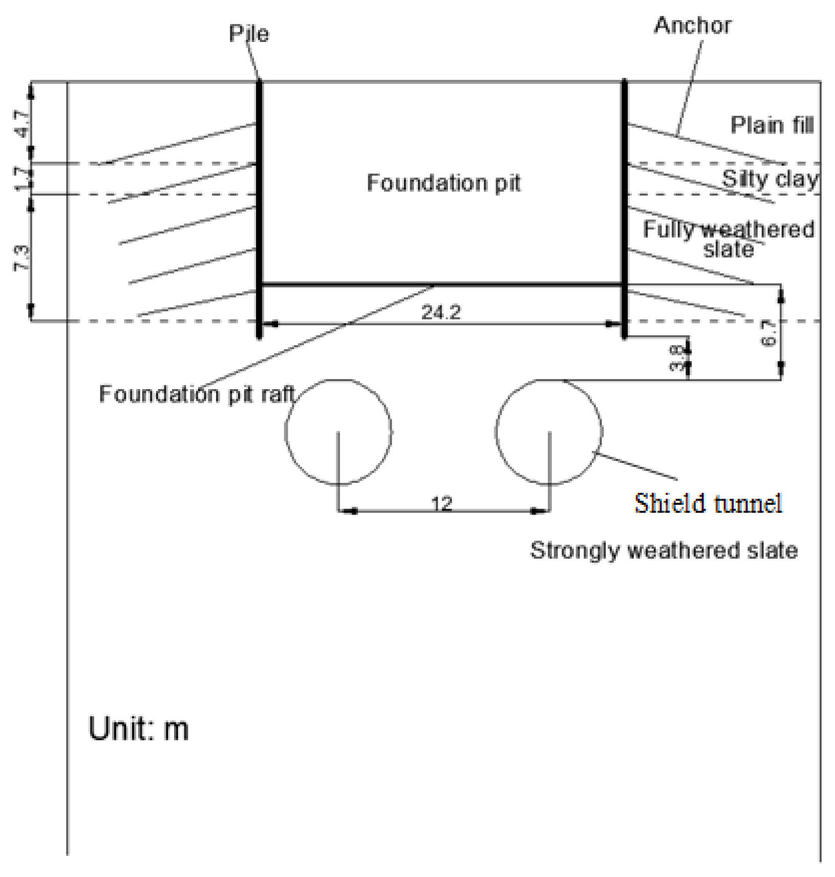
A section of Changsha Metro Line 6 is a double-line shield tunnel, which undercrosses an existing foundation pit with a length of 70.4 m, a width of 24.2 m and a depth of 11.6 m. The base of the foundation pit is only 6.7 m from the top of the tunnel and is provided with a raft with a thickness of 1.2 m. The foundation pit is supported by a pile-anchor system with five anchors around the foundation pit. The lengths of the anchors are 12–23 m. The interval between the retaining piles is 2.2 m, the diameter of the retaining piles is 1.2 m and the vertical distance between the bottom of the pile and the top of tunnel is only 3.8 m.
The diameter of the cutter head of the shield machine used in shield construction is 6.2 m, and the thickness and width of the segment are 35 cm and 1.5 m, respectively. The tunnels, foundation pit and stratum are shown in
Figure 1.
3. Model and Parameters
Midas GTS NX is a special finite element analysis software for analyzing geotechnical and tunnel structures. It has comprehensive geotechnical field analysis functions. It is suitable for geotechnical engineering, tunnel engineering, foundation pit engineering and other fields and has a large number of geotechnical constitutive models. This paper explores the deformation of and the laws of mechanical characteristics of the foundation pit structure and the tunnel itself induced by the shield tunnel. This software has been used and validated by many researchers to study different geotechnical problems related to tunnels and buried infrastructure [
25,
26,
27,
28]; therefore, Midas GTS NX is used for analysis.
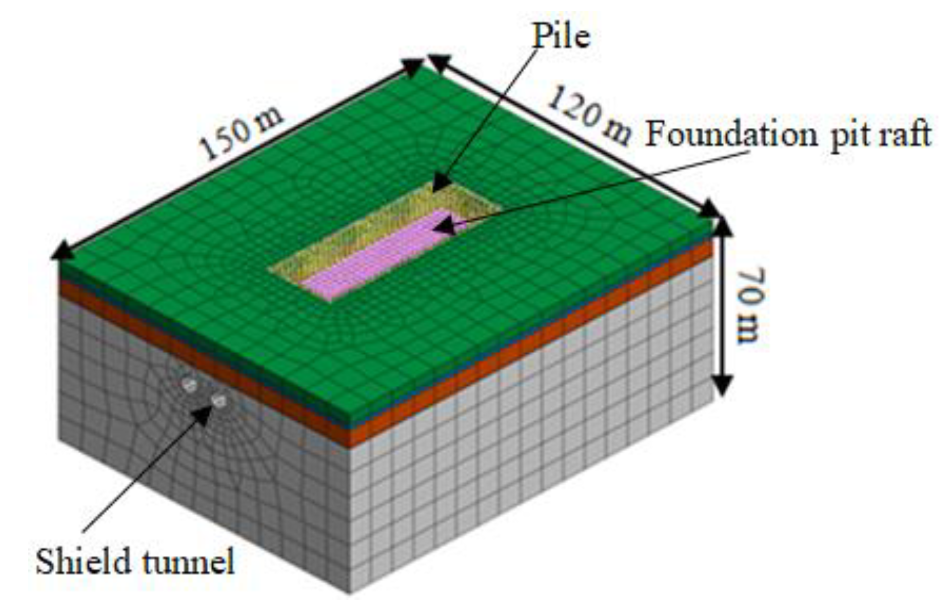
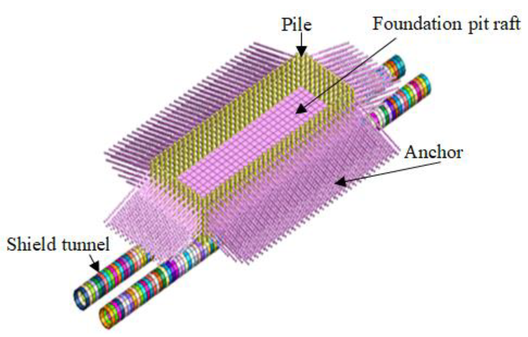
In this paper, Midas GTS NX is used to establish the three-dimensional solid model of double-line tunnels. Considering the boundary effects of the foundation pit and tunnel, the length, width and height of the model are 150 m, 120 m and 70 m, respectively. As the slope of each layer is small and the maximum gradient of all soil layers is 2‰, it is considered a horizontal stratum in the model. The soil and the pipe segments are simulated by solid elements. The grouting layer is simulated by a first-class and homogeneous equivalent layer elastic body [
29]. The shield shell is simulated by two-dimensional plate elements, and the pile and anchor are simulated by beam elements. The three-dimensional solid finite element model, the foundation pit support structure and the tunnel are shown in
Figure 2 and
Figure 3, respectively.
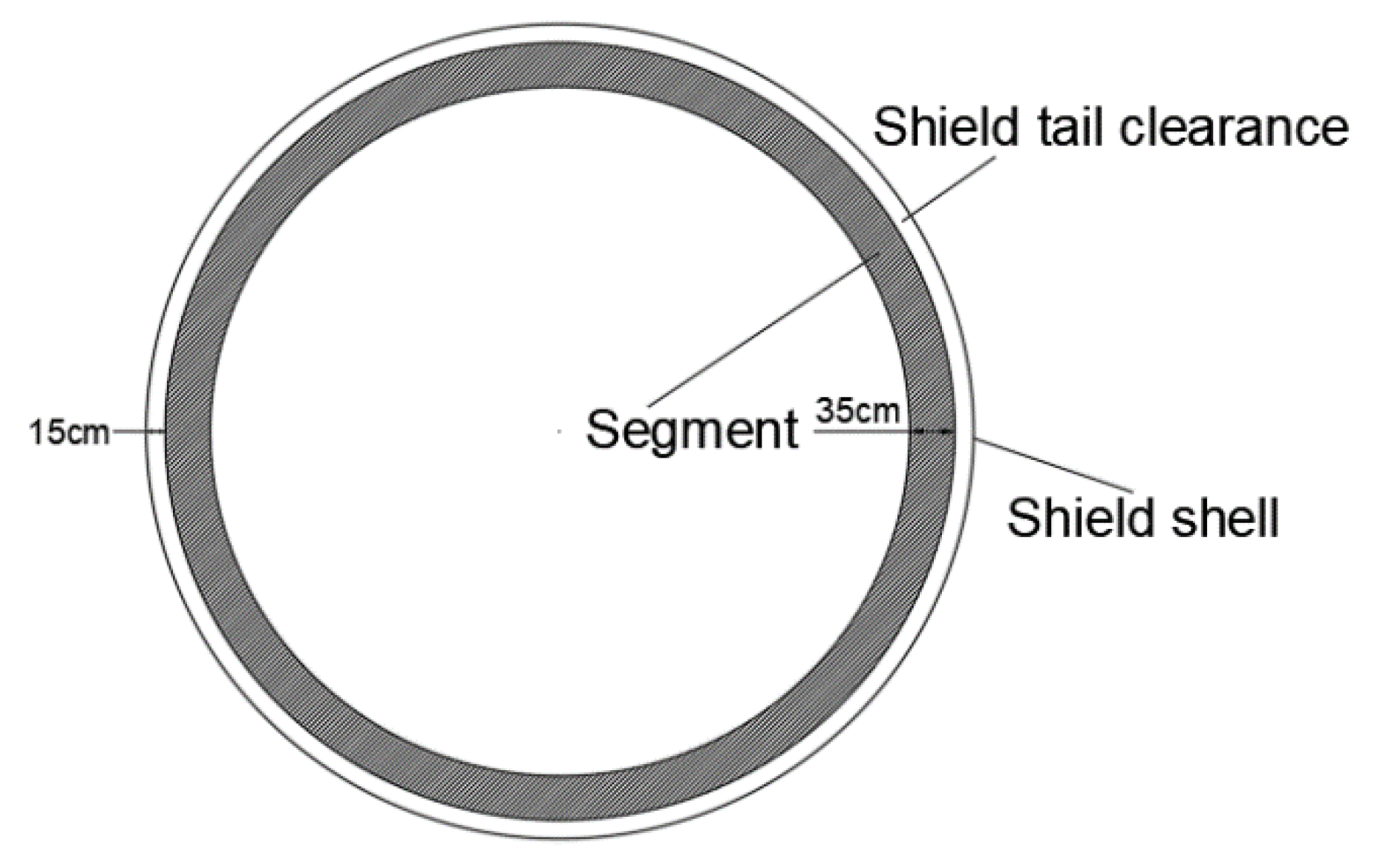
The values of shield tunnel construction parameters are as follows: The shield tail clearance is 15 cm, as it is shown in
Figure 4. The thickness of the grouting layer is 20 cm, the grouting pressure is 100 kPa and the driving pressure is 200 kPa. The parameters are the same as those in Reference [
29]. If there is no special description below, the value of each parameter is not changed.
At present, the Mohr–Coulomb model is mainly based on the Mohr–Coulomb elastic–plastic model in the numerical simulation analysis because of its few parameters and easiness to obtain. However, the Mohr–Coulomb failure criterion has some defects. During excavation and unloading, the assumed elastic modulus is used for the resilience modulus and compression modulus of soil, resulting in large error in the calculation results. The modified Mohr–Coulomb model is the optimization of the Mohr–Coulomb model. The elastic modulus can be set according to loading and unloading, which is more suitable for simulation study of foundation pit excavation; therefore, the modified Mohr–Coulomb model is selected for numerical simulation.
The stratum from top to bottom are plain fill, silty clay, fully weathered slate and strongly weathered slate, respectively, as shown in
Figure 1. The physical parameters in the model are shown in
Table 1.
In the construction simulation, two segments with widths of 3 m are used as construction stages. In addition, in order to simulate the synchronous grouting and hardening process of the shield machine, the process of slurry softening to hardening is simulated by changing the elastic modulus of the grouting layer. The elastic moduli of the grouting layer during the grouting hardening process are 1 MPa and 10 MPa in the softening and hardening stages, respectively [
1]. Each construction stage is simulated as follows:
- (1)
In the presence of existing foundation pits, the initial in-situ stress is balanced, the displacement is reset and the consolidation subsidence is completed.
- (2)
The shield machine drives forward with the width of two segments at a time, and the temporary support for the shield shell is provided.
- (3)
Repeat Step 2, remove the last shield shell and add the segments and the grouting layer (softening) at the location of removing the shield shell until the excavation distance reaches 8 segment widths (12 m), and then change the first grouting layer from softening to hardening.
- (4)
Repeat Step 3 until the shield tunnel is completed.
4. Numerical Model Verification
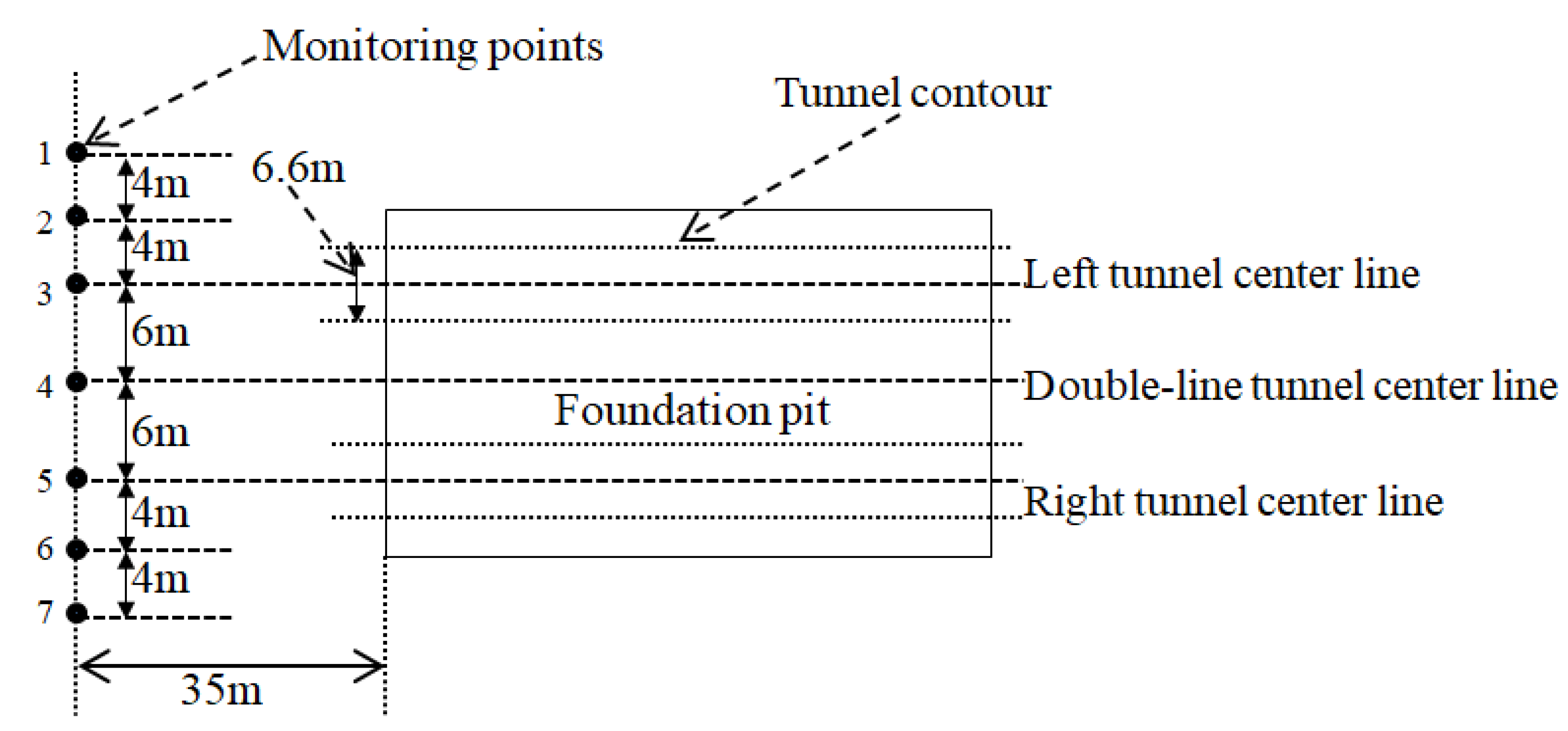
Considering the limitations of ground surface conditions, seven monitoring points shown in
Figure 5 are set at each cross section to monitor ground surface subsidence. The numerical simulation and monitoring data of ground surface subsidence along the transverse direction are shown in
Figure 6 and
Table 2.
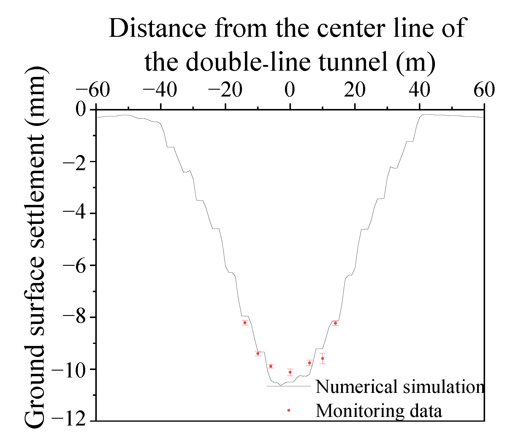
It can be seen from
Figure 6 that a single peak, approximately V-shaped subsidence trough is formed on the ground surface due to tunneling, which is similar to the result of Reference [
30], and the subsidence distribution of the numerical simulation is similar to that of the monitoring data. It can also be seen from
Figure 6 that the monitoring data of each monitoring point have a certain error. This is because in the actual measurement process, the monitoring data have a certain deviation due to the measurement error of the instrument and the complete subsidence of the ground surface. However, the data’s floating range is relatively small, and the maximum standard deviation is 0.209, so the monitoring data can meet the accuracy requirements. In addition, it can be seen from
Table 2 that there is a certain error between the numerical simulation results and the monitoring data. The reason is that the numerical simulation does not consider the deformation of the soil caused by factors such as the friction of the shield shell and the rotation and cutting of the cutter head during the shield tunneling process. There will be some errors due to instruments, equipment, operation and other reasons in the actual monitoring process, but the maximum error between the numerical simulation and the monitoring data is 5.44%, and they are relatively consistent. Therefore, the above numerical model may be considered reliable and may study the influence law of the shield tunnel undercrossing the existing foundation pit.
5. Numerical Simulation Results
5.1. Analysis of Foundation Pit Structure
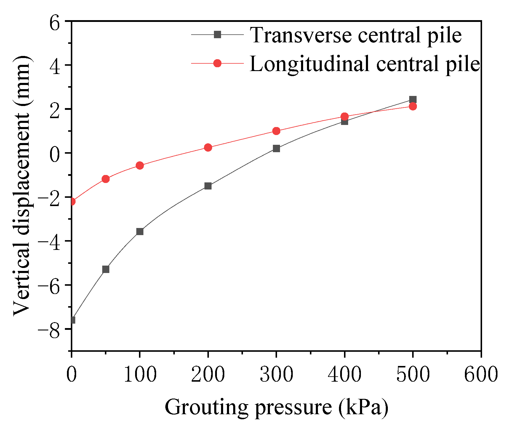
5.1.1. Analysis of Pile Subsidence
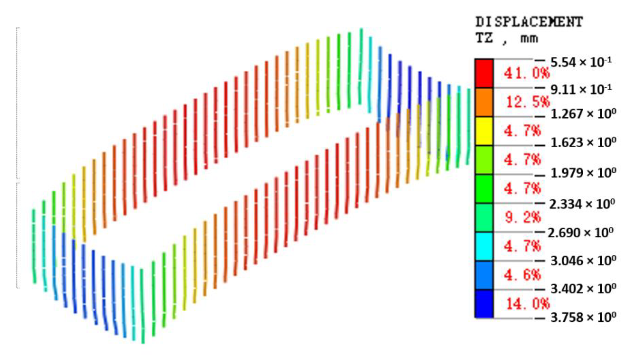
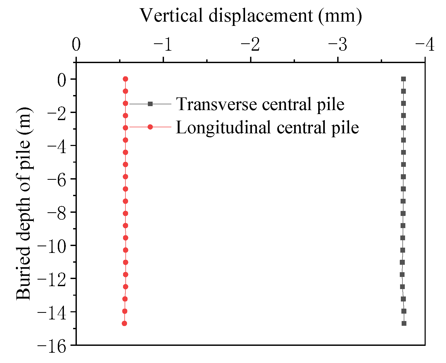
The middle piles arranged in the vertical and horizontal directions are selected as the research objects (hereafter referred to as the longitudinal central piles and the transverse central piles). The vertical displacement nephogram of the longitudinal and transverse central piles and the curve of vertical displacement of piles with their buried depths are shown in
Figure 7 and
Figure 8, respectively.
As can be seen from
Figure 7, the vertical subsidence of piles is produced during tunneling, and the subsidence of the transverse central piles is larger, up to 3.76 mm. The subsidence of piles is uneven: large at both ends and small in the middle along the longitudinal direction and small at both ends and large in the middle along the transverse direction, similar to the result of Reference [
31]. The reason is that the integrity of the soil in the foundation pit area is greatly increased due to the role of the pile anchor, resulting in small soil subsidence in the foundation pit area and large soil subsidence at both ends. It can be seen from
Figure 8 that tunnel excavation has little influence on the subsidence of the longitudinal piles; the maximum vertical displacement is only 0.55 mm and the settlement of the transverse central pile is significantly greater than that of the longitudinal central pile, about 6.8 times. Therefore, special attention should be paid to the settlement of the transverse central pile caused by the shield. The vertical displacement of each position of the longitudinal and transverse central piles is almost the same, that is, the overall subsidence of the pile is produced.
5.1.2. Analysis of Deformation and Stress of Anchors
In order to analyze the deformation and stress changes of anchors, the intermediate anchors in the longitudinal and transverse directions are selected as the research objects (hereafter referred to as longitudinal and transverse anchors). The variation curves of vertical displacements of longitudinal and transverse anchors along their lengths are shown in
Figure 9, and the tensile stress values of anchor bolts before and after tunnel excavation are listed in
Table 3.
It can be seen from
Figure 9 that tunnel excavation has a greater influence on the vertical displacement of the longitudinal anchor, where the maximum value is 10.33 mm; however, it has a smaller influence on the vertical displacement of the transverse anchor, where the maximum value is only 0.6 mm. The reason is that the longitudinal anchor is located in the central area affected by tunnel excavation, so the vertical deformation is large, but the transverse anchor is located outside the tunnel area, and the influence is relatively small.
At the same time, it can be found that the vertical displacement at both ends of the longitudinal anchor is inconsistent: the maximum is 10.33 mm, and the minimum is 3.54 mm. The inconsistent vertical deformation at both ends inevitably leads to the bending deformation of the whole anchor, resulting in additional stress. It can also be found from
Table 3 that the tensile stress of the longitudinal anchor increases from 111 MPa to 147 MPa, an increase of 32.4%; however, the tensile stress of the transverse anchor increases only 0.8%. Thus, the tensile stress of the longitudinal anchor rod increases by 31.6% more than that of the transverse anchor rod. The reason is that outside the foundation pit, the soil forms a large uneven settlement along the longitudinal direction and a small uneven settlement in the transverse direction, resulting in greater additional stress in the longitudinal direction. Therefore, special attention should be paid to the stress and deformation of the longitudinal anchor.
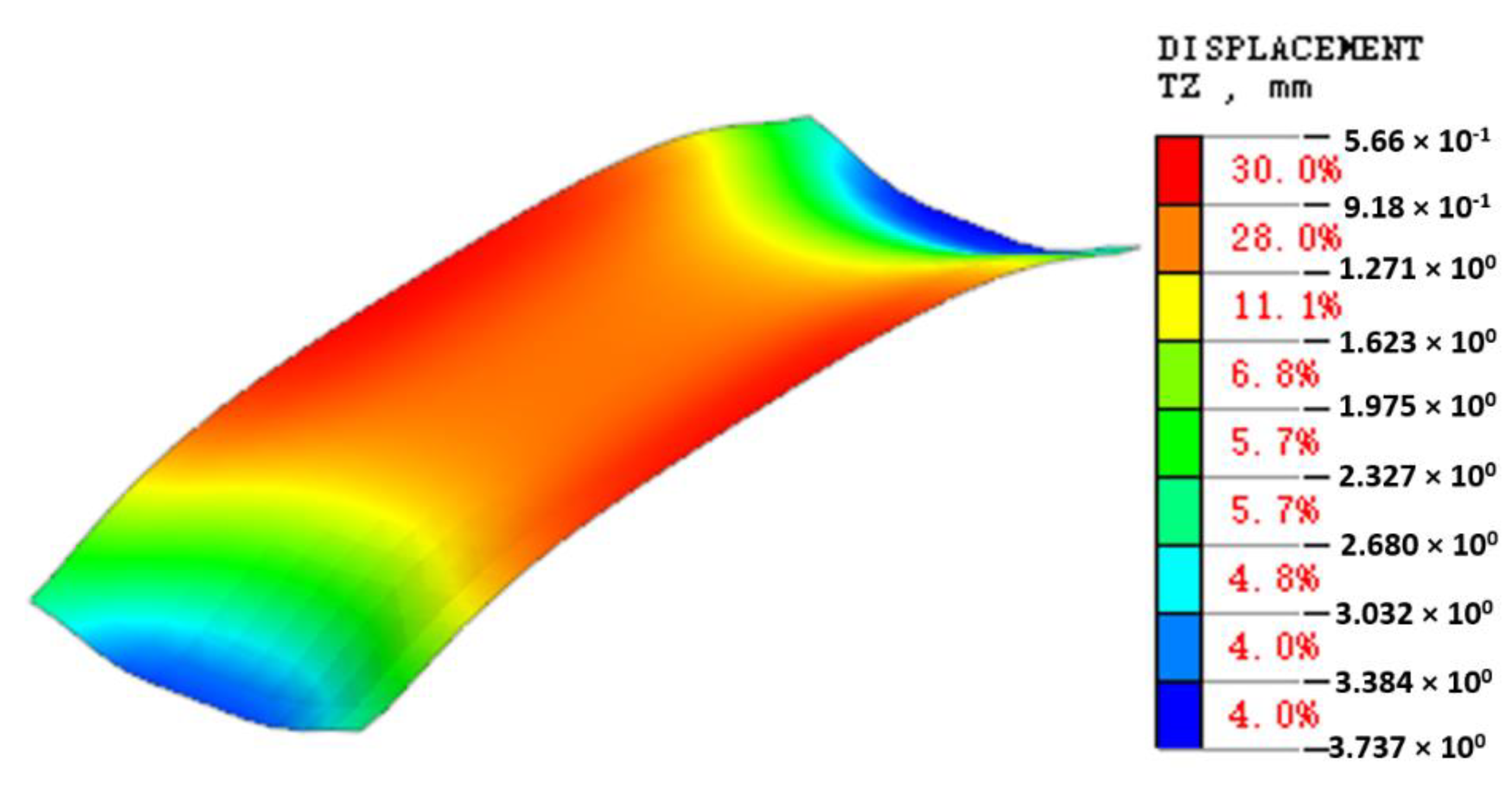
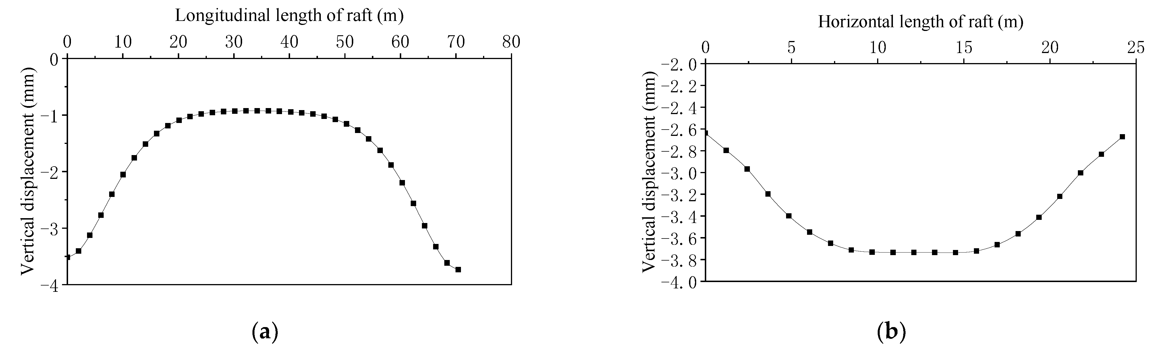
5.1.3. Deformation Analysis of Foundation Pit Raft
The vertical displacement nephogram of the foundation pit raft and the vertical displacements of the foundation pit raft along the longitudinal and transverse directions are shown in
Figure 10 and
Figure 11, respectively.
It can be seen from
Figure 10 that after tunnel excavation, the foundation pit raft is settling as a whole. The maximum value of subsidence is 3.74 mm, which is located at both ends, the minimum value of subsidence is 0.57 mm, and the difference is 3.17 mm, resulting in uneven deformation of the whole raft.
It can also be seen from
Figure 11 that the raft sinks unevenly along the longitudinal and transverse directions. It can be seen that the foundation pit raft is arched in the longitudinal direction, that is, the deformation shape “large subsidence at both ends and small subsidence in the middle”, and concave in the transverse direction, that is, the deformation shape “small subsidence at both ends and large subsidence in the middle”. The reason is that due to the action of the pile anchor, the soil has uneven subsidence along the longitudinal direction, that is, the subsidence at both ends is large and the subsidence in the middle is small, and the soil along the transverse direction will form a V-shaped subsidence groove. Therefore, in general, the deformation of the foundation pit raft shown in
Figure 8, that is, the shape of an “arch with four corners warping upward”, is formed.
It can also be seen from
Figure 11 that the raft sinks unevenly along the longitudinal and transverse directions. It can be seen that the foundation pit raft is arched in the longitudinal direction, that is, the deformation shape “large subsidence at both ends and small subsidence in the middle”, and concave in the transverse direction, that is, the deformation shape “small subsidence at both ends and large subsidence in the middle”. Therefore, in general, the deformation of the foundation pit raft shown in
Figure 8, that is, the shape of an “arch with four corners warping upward”, is formed.
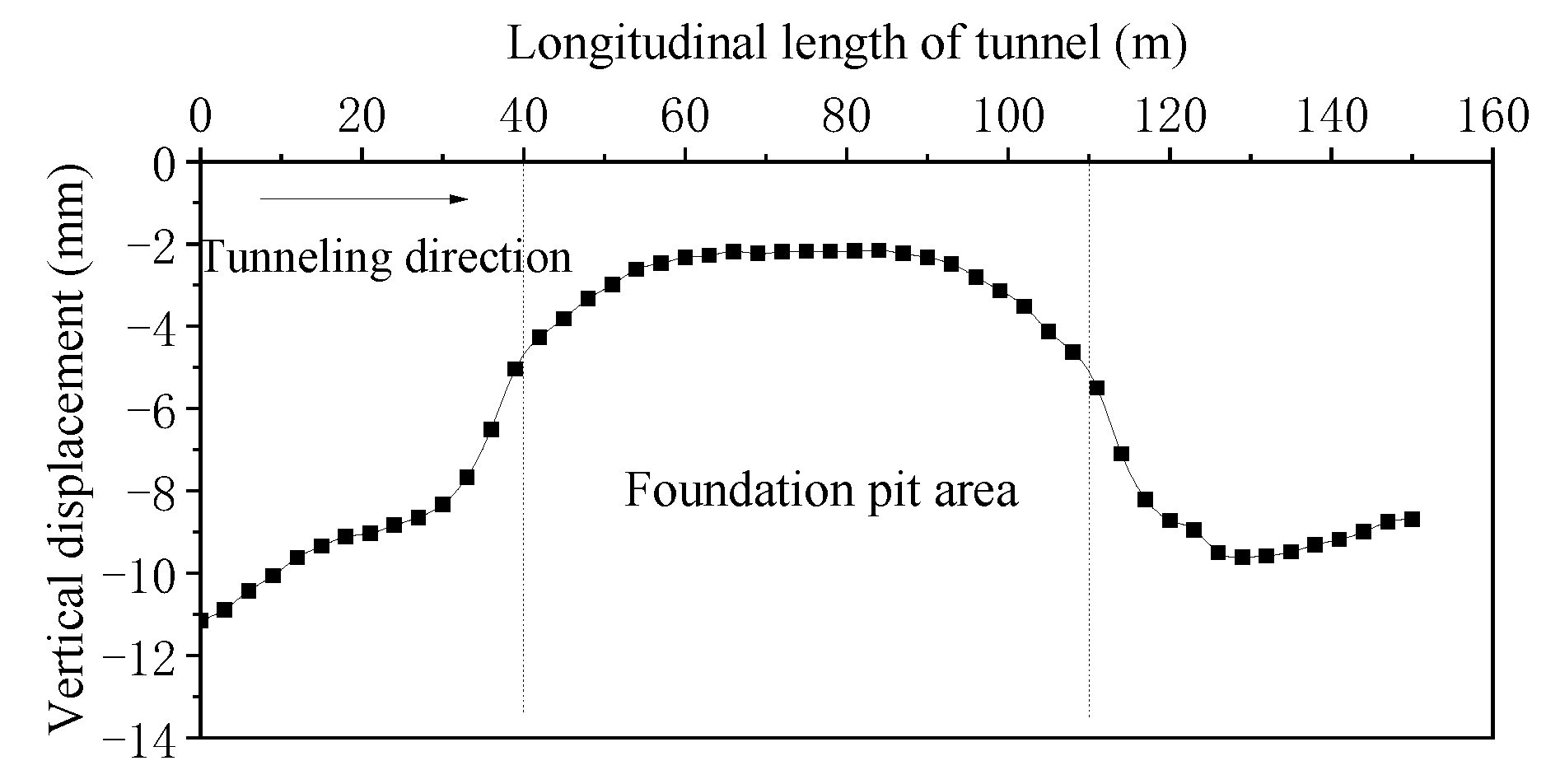
5.2. Analysis of Tunnel Settlement
The vertical displacement of the tunnel along the longitudinal direction is shown in
Figure 12.
It can be seen from
Figure 12 that the subsidence is uneven. The large subsidence is located at the outside of the foundation pit, and the maximum value is 11.15 mm. The small subsidence is located at the underpart of the foundation pit, and the minimum value is 2.13 mm. The maximum subsidence difference of the tunnel is 9.02 mm, forming a “hat” deformation shape, with “large subsidence on both sides and small subsidence in the middle”. It is similar to the result in Reference [
32], that is, the tunnel has uneven subsidence in the longitudinal direction. The reason is that when the tunnel undercrosses the foundation pit, the buried depth of the tunnel is not equal. When the buried depth of the tunnel is greater, its stress is greater. The uneven stress of the tunnel inevitably leads to inconsistent vertical subsidence of the tunnel, thus forming a curve as shown in
Figure 12. The tunnel with greater additional stress is due to its uneven subsidence in the longitudinal direction. In serious cases, it will crack the segment and endanger the safety of the tunnel. Therefore, special attention should be paid to it.
6. Influence of Grouting Pressure
In order to explore the influence of grouting pressure on the deformation and mechanical characteristics of the foundation pit supporting structures and the tunnel, seven values of grouting pressure with 0 kPa, 50 kPa, 100 kPa, 200 kPa, 300 kPa, 400 kPa and 500 kPa are considered.
6.1. Influence of Grouting Pressure on Pile
The curves of maximum vertical displacement and tensile stress of the pile with grouting pressure are shown in
Figure 13 and
Figure 14.
It can be seen from
Figure 13 that the influence laws of grouting pressure on the maximum vertical displacements of the transverse and longitudinal central piles are similar. With the increase in grouting pressure, the maximum vertical displacement of the pile gradually decreases, and there is an obvious nonlinear relation between them: when the grouting pressure increases to a certain value, the pile moves upward. The reason is that when the grouting pressure is high, the whole soil moves upward, driving the pile to move upward.
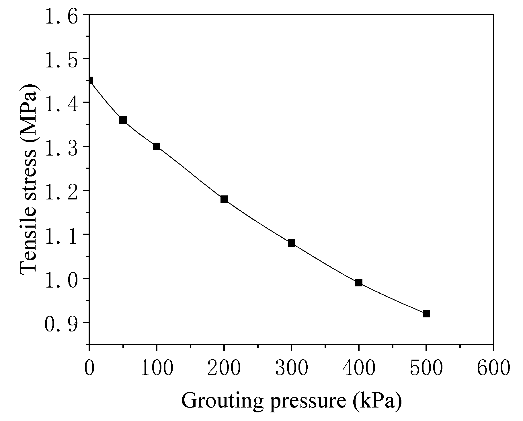
It can be seen from
Figure 14 that with the increase in grouting pressure, the maximum tensile stress of the pile gradually decreases. When the values of grouting pressure are 50 kPa, 100 kPa, 200 kPa, 300 kPa, 400 kPa and 500 kPa, the maximum tensile stresses of the pile are 1.36 MPa, 1.3 MPa, 1.18 MPa, 1.05 MPa, 0.99 MPa and 0.92 MPa, respectively, which decrease by 4.6%, 10.2%, 12.4%, 6.1% and 7.6% year-by-year. At the same time, with the increase in grouting pressure, the maximum tensile stress curve of the pile gradually slows down. It can be seen that the effect of grouting pressure gradually decreases with the increase in grouting pressure. Therefore, it is recommended that the grouting pressure should not exceed 300 kPa.
6.2. Influence of Grouting Pressure on Anchor
The results in the
Section 5.1.1 show that tunnel excavation has little influence on the transverse anchor. Therefore, this section focuses on the influence law of the grouting pressure on the longitudinal anchor. The curves of vertical displacement and tensile stress of the longitudinal anchor with grouting pressure are shown in
Figure 15 and
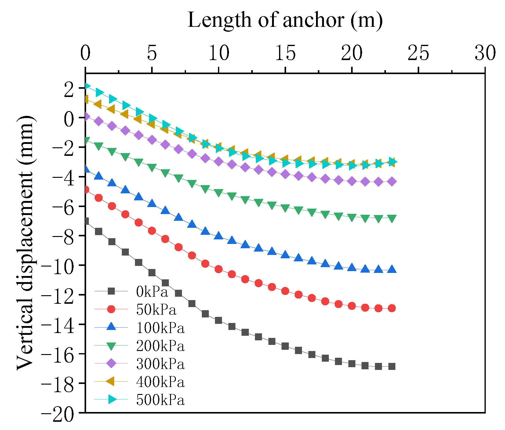
Figure 16.
Figure 15 shows that even if the grouting pressure is different, the law of uneven subsidences of the anchor along the longitudinal direction is similar, that is, the subsidence at one end is large and the subsidence at the other end is small. The reason is that the soil subsidence along the longitudinal direction is uneven and the anchor bolt deforms unevenly with the soil. With the increase in grouting pressure, the maximum subsidence of the anchor gradually decreases. When the values of grouting pressure are 50 kPa, 100 kPa, 200 kPa, 300 kPa, 400 kPa and 500 kPa, the maximum subsidences of the anchor are 16.85 mm, 12.92 mm, 10.33 mm, 6.78 mm, 4.32 mm, 3.04 mm and 2.99 mm, respectively, which decreases by 23.4%, 20.1%, 34.3%, 36.2%, 29.7% and 1.5% year-by-year. It can be seen from
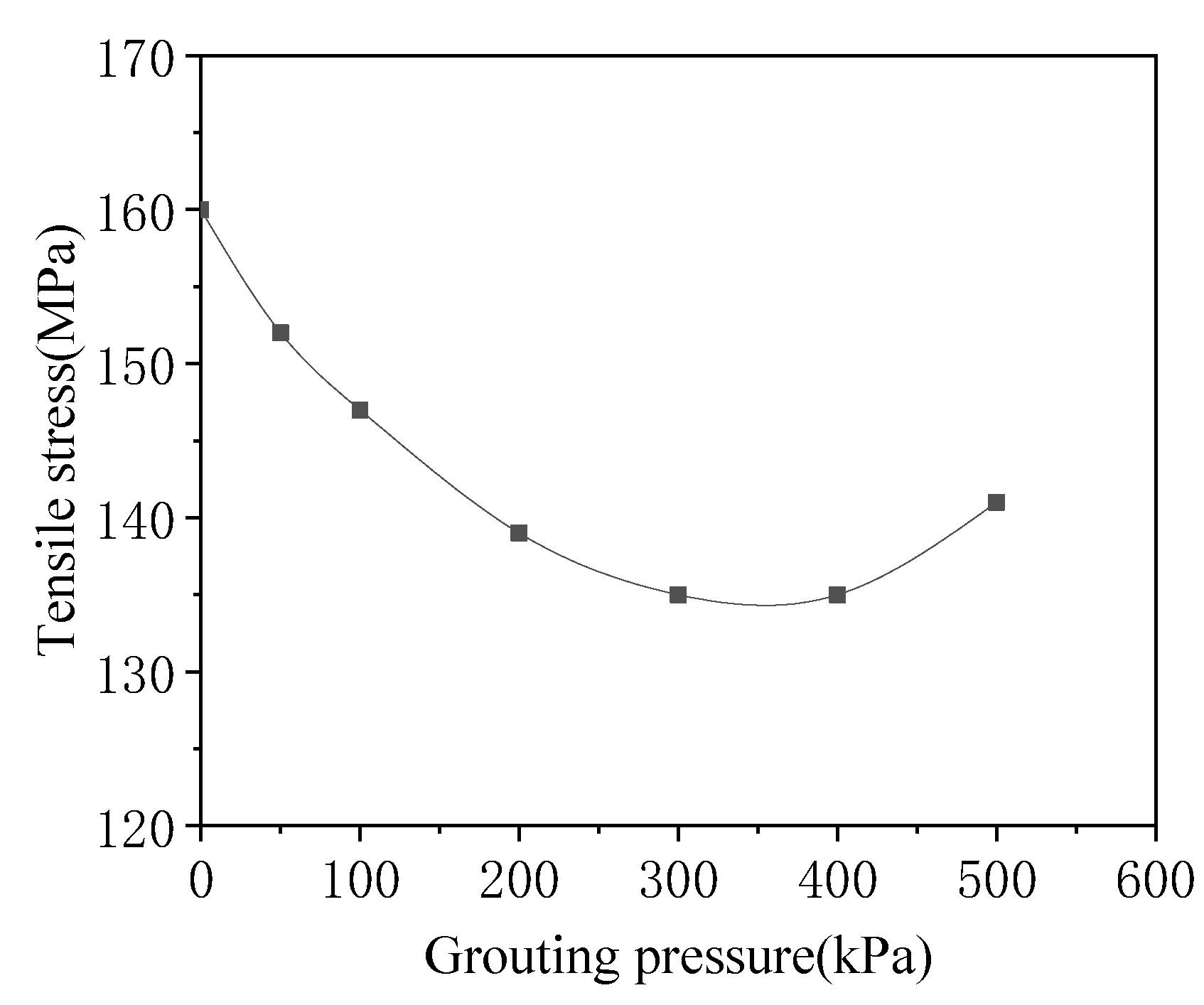
Figure 16 that when the grouting pressure is less than 350 kPa, the tensile stress of the anchor gradually decreases with the increase in the grouting pressure, but when it is greater than 350 kPa, the tensile stress of the anchor increases with the increase in the grouting pressure.
The above results show that properly increasing the grouting pressure can improve the deformation and stress of the anchor. It is recommended that the grouting pressure should be less than 350 kPa.
6.3. Influence of Grouting Pressure on Foundation Pit Raft
The variation curves of the vertical displacement of the raft along the longitudinal and transverse directions under different grouting pressures are shown in
Figure 17 and
Figure 18, respectively.
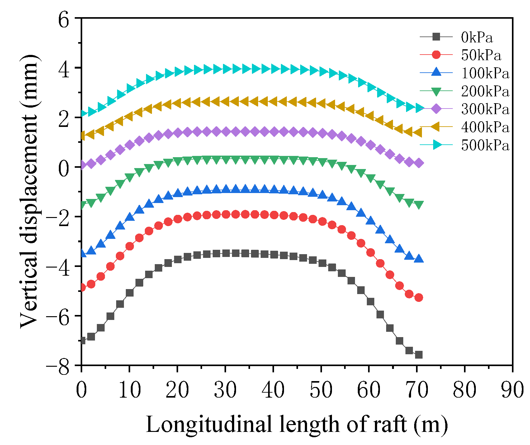
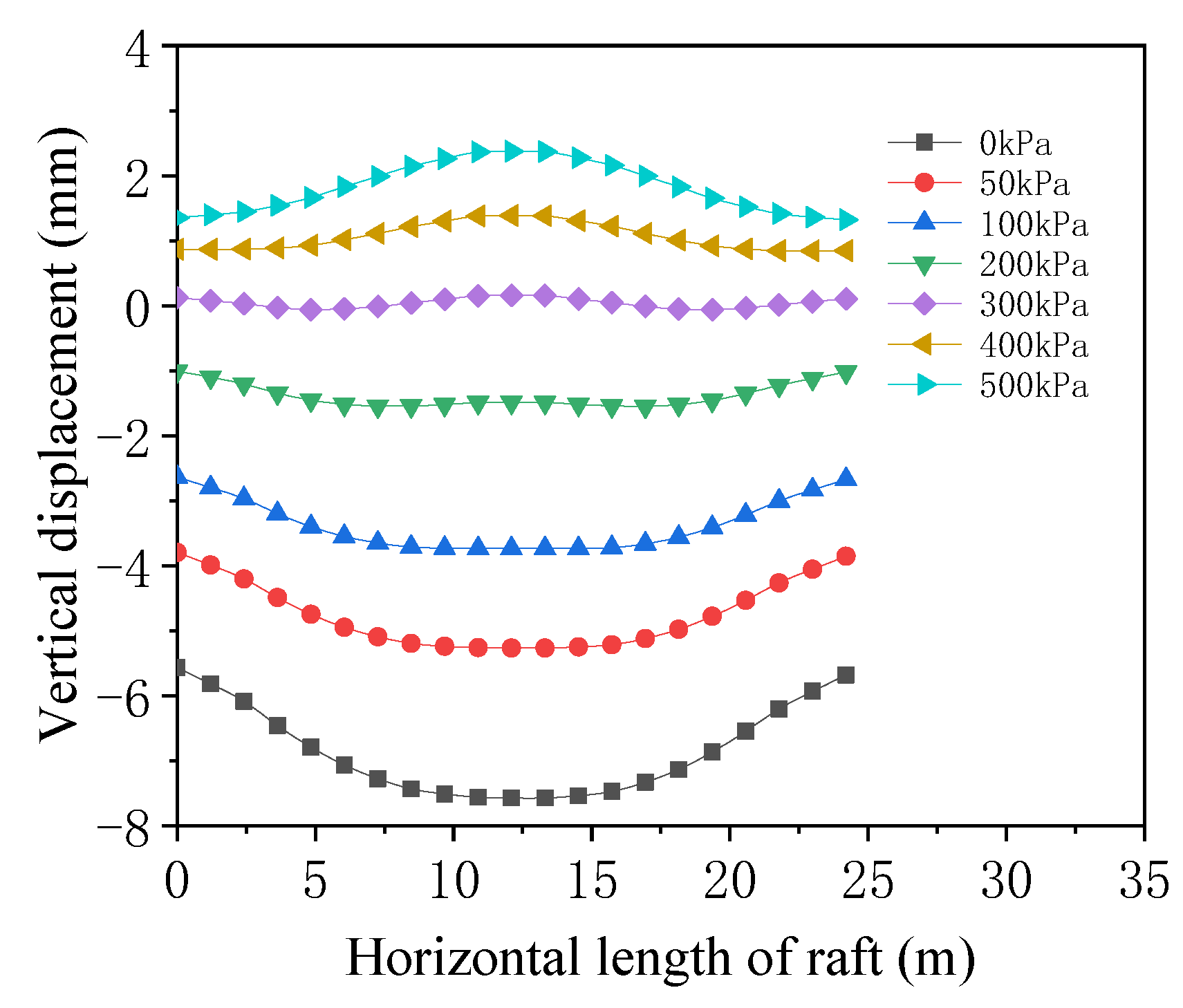
It can be seen from
Figure 17 that although the grouting pressure is different, the uneven subsidence law of the raft along the longitudinal direction is similar, which is in the deformation shape “large subsidence at both ends and small subsidence in the middle”. In addition, with the increase in grouting pressure, the subsidence of the raft at both ends and the middle gradually decreases. When the grouting pressure increases to a certain value, the upward displacement of raft is produced, and its value increases with the increase in grouting pressure.
It can be seen from
Figure 18 that with the increase in grouting pressure, the subsidence in the middle of the raft gradually decreases. When it is 200 kPa, there is almost no uneven subsidence of the raft along the transverse direction. When it exceeds 200 kPa, the upward displacement of the raft in the middle is produced. The vertical deformation of the raft along the transverse direction changes from downward concave to upward convex, the reason being that the increase in grouting pressure will squeeze the soil, make the soil arch up and then reduce the subsidence of the foundation pit raft.
It can be seen that larger or smaller grouting pressure causes uneven deformation of the raft, resulting in additional stress on the raft. Therefore, the grouting pressure should be reasonably selected, which should not be too large or too small. It is recommended that the grouting pressure should be less than 300 kPa.
6.4. Influence of Grouting Pressure on Deformation and Mechanical Characteristics of Tunnel
Only according to the longitudinal deformation curve of the tunnel, it is impossible to truly and comprehensively understand the safety condition of the tunnel. It is also necessary to analyze the stress state of the tunnel. In order to simplify the calculation, the longitudinal equivalent continuity model proposed by Shiba et al. [
33,
34] is referenced, which simplifies the tunnel and regards it as a homogeneous ring in the transverse direction. In the longitudinal direction, the tunnel is regarded as a uniform continuous straight beam by the method of stiffness equivalence. At the same time, based on the assumption of References [
35,
36] and the Euler–Bernoulli theory [
37,
38,
39,
40], there is Formula (1):
where
ρ is the curvature radius of the tunnel,
M is the longitudinal bending moment of the tunnel and
EI is the longitudinal equivalent bending stiffness of the tunnel.
Formula (1) shows that the bending moment is inversely proportional to the radius of curvature of the tunnel, so the radius of curvature of the tunnel can be used as a reference standard to measure the stress of the tunnel.
At the same time, in order to improve the accuracy of the law obtained by numerical simulation, based on the subsidence curve along the longitudinal direction of the tunnel, this paper carries out cubic spline interpolation fitting on the curve using Matlab. Considering the situation of the tunnel, the first derivative function at both ends of the curve is 0 as the boundary condition, and the minimum curvature radius of the longitudinal subsidence curve of the tunnel is obtained as the standard to measure the stress condition of the tunnel, in order to check the accuracy of the influence law obtained by numerical simulation.
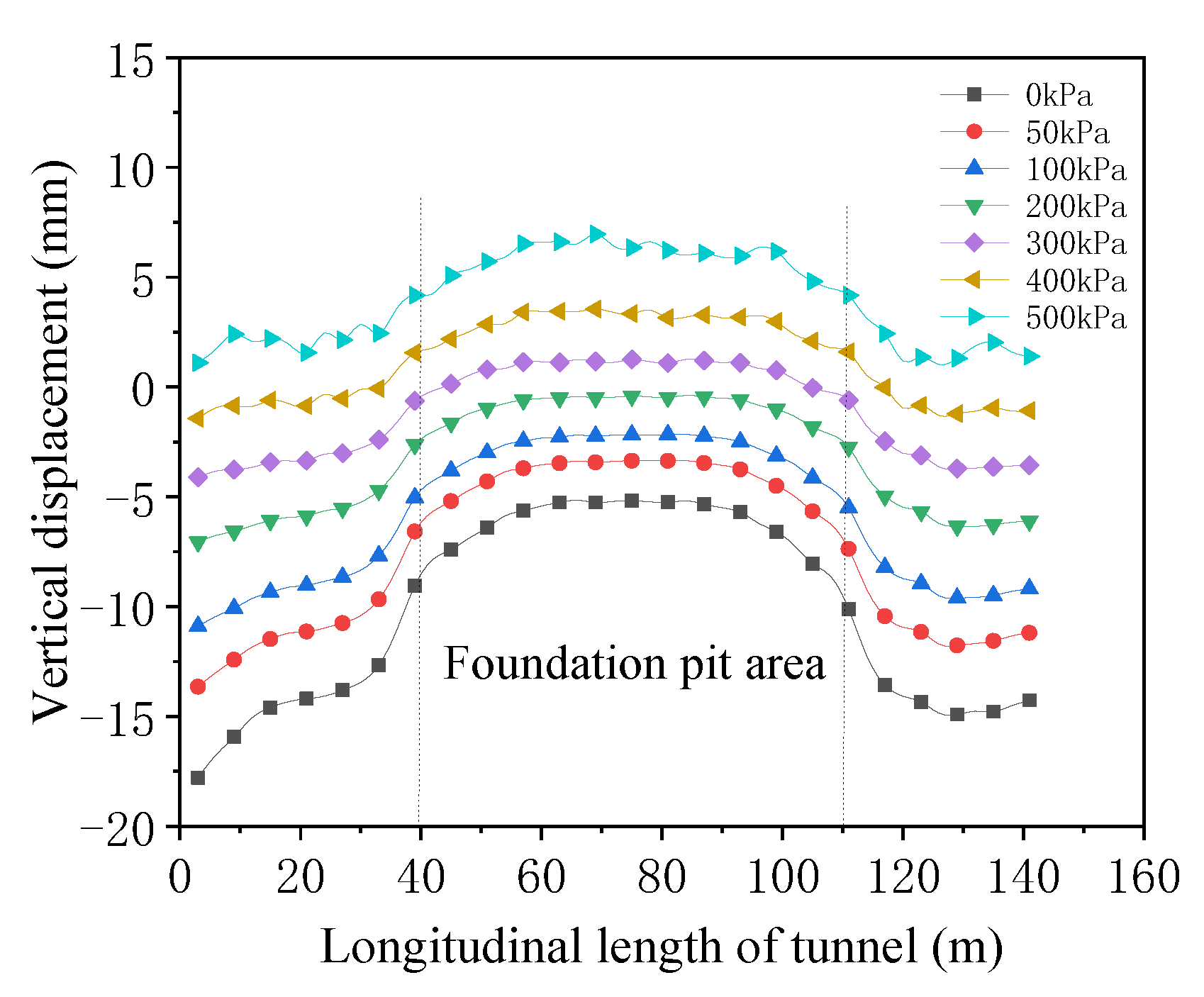
It can be seen from
Figure 19 that the laws of longitudinal deformation of the tunnel are similar for different grouting pressures, and the deformation shape is “large subsidence at both ends and small subsidence in the middle”. With the increase in grouting pressure, the subsidence of the tunnel gradually decreases. When the grouting pressure exceeds 400 kPa, the tunnel in the foundation pit area appears to be overburdened. This is due to the tunnel in the foundation pit area being shallow, which causes the larger grouting pressure to make the soil arch up and then the tunnel lifts.
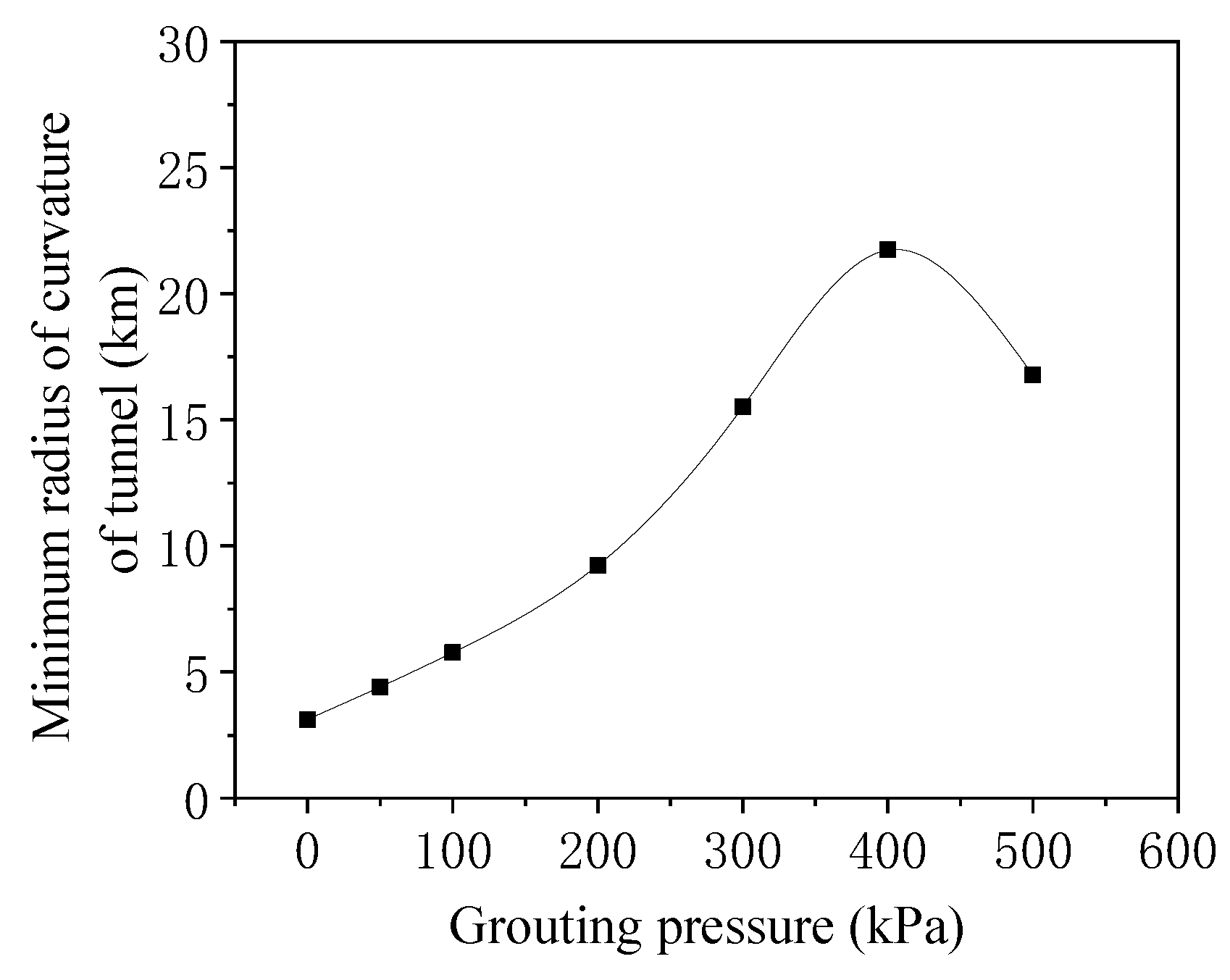
It can be seen from
Figure 20 that with the increase in grouting pressure, the maximum longitudinal subsidence difference of the tunnel gradually decreases. However, when the grouting pressure is 350 kPa and increases, the subsidence difference of the tunnel gradually increases.
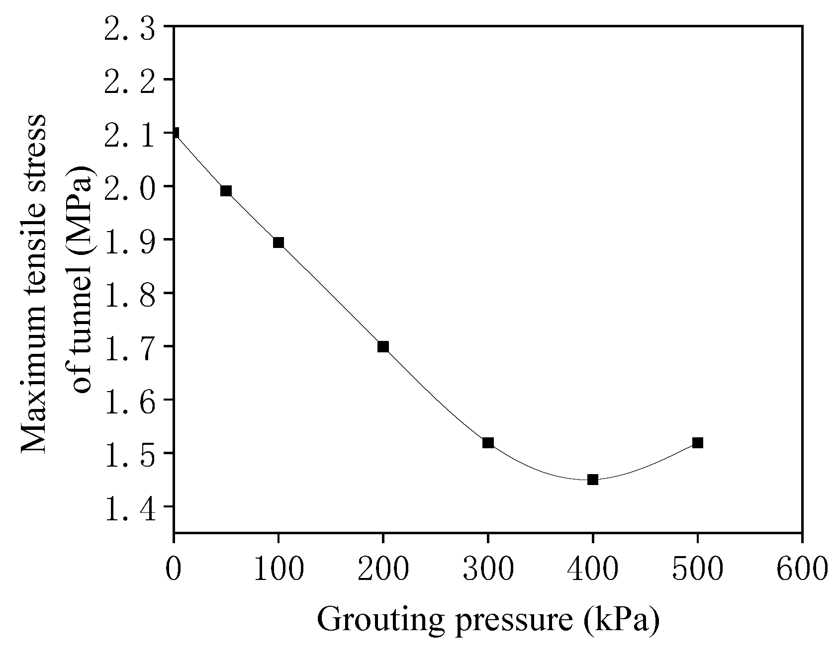
Figure 21 shows that when the grouting pressure is less than 400 kPa, the maximum tensile stress of the tunnel decreases with the increase in grouting pressure. However, when the grouting pressure is greater than 400 kPa, the maximum tensile stress of the tunnel increases with the increase in grouting pressure. It can be seen from
Figure 22 that when the grouting pressure is less than 400 kPa, the minimum radius of curvature of the tunnel increases with the increase in grouting pressure, but when the grouting pressure is greater than 400 kPa, the radius of curvature decreases with the increase in grouting pressure. Therefore, by comparing the calculation results in
Figure 21 and
Figure 22, it can be found using MIDAS GTS NX and Matlab that the grouting pressure has the same influence on the tunnel stress, which is in a certain range of grouting pressure. the tunnel tensile stress and curvature decrease with the increase in grouting pressure, and when grouting pressure exceeds a certain value, it changes in the opposite direction. It can also verify that the influence of grouting pressure on tunnel stress is reasonable.
In summary, appropriately increasing the grouting pressure can significantly improve the longitudinal uneven subsidence and stress of the tunnel, but the grouting pressure should not be too large; it is recommended that the grouting pressure should be less than 350 kPa.
7. Influence of Symmetrical Segmented Pressure
Based on the above results that the same grouting pressure leads to the longitudinal uneven subsidence of the tunnel, in order to reduce the uneven subsidence and stress of the tunnel and ensure the safety of the tunnel, a method of applying different grouting pressure in sections is proposed. This method is to apply larger grouting pressure to the tunnel outside the foundation pit area and smaller grouting pressure in the foundation pit area (hereafter referred to as segmented pressure).
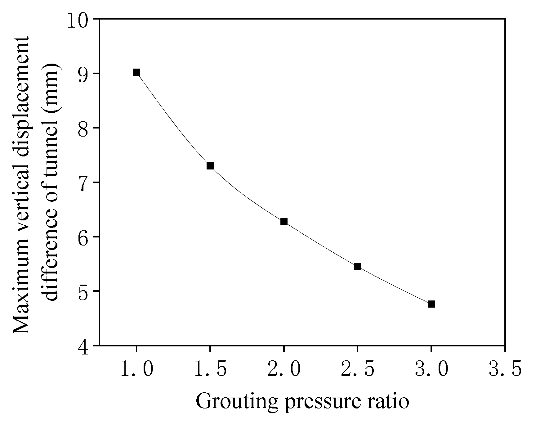
In order to explore the effect of segmented pressure, the grouting pressure applied to the tunnel in the foundation pit area is set to 100 kPa, and the grouting pressure of the tunnel outside the foundation pit area is changed. The ratio of the grouting pressure of the tunnel outside the foundation pit area to the grouting pressure of the tunnel in the foundation pit area is referred to as the grouting pressure ratio. Based on the above calculation results, it is recommended that the grouting pressure should not exceed 350 kPa. Therefore, the grouting pressure ratio is selected as 1, 1.5, 2, 2.5 and 3. The influence of segmented pressure on longitudinal displacement difference, tensile stress and radius of curvature of the tunnel is shown in
Figure 23,
Figure 24 and
Figure 25.
As can be seen from
Figure 23, compared with the grouting pressure ratio of 1, i.e., without segmented pressure, the use of segmented pressure can significantly reduce the longitudinal uneven subsidence of the tunnel. With the increase in grouting pressure ratio, the maximum uneven subsidence difference of the tunnel gradually decreases, the main reason being that the segmented pressure can offset the uneven stress of the tunnel caused by the buried depth of the soil above the tunnel and then reduce the longitudinal uneven subsidence difference of the tunnel. When the grouting pressure ratios are 1, 1.5, 2, 2.5 and 3, respectively, the maximum subsidence differences of the tunnel are 9.02 mm, 7.31 mm, 6.27 mm, 5.45 mm and 4.76 mm, respectively. Compared to the maximum subsidence difference of the tunnel with the grouting pressure ratio of 1, the longitudinal subsidence differences of the tunnel are reduced by 19.1%, 30.5%, 39.6% and 47.2%, respectively, for the grouting pressure ratios of 1.5, 2, 2.5 and 3.
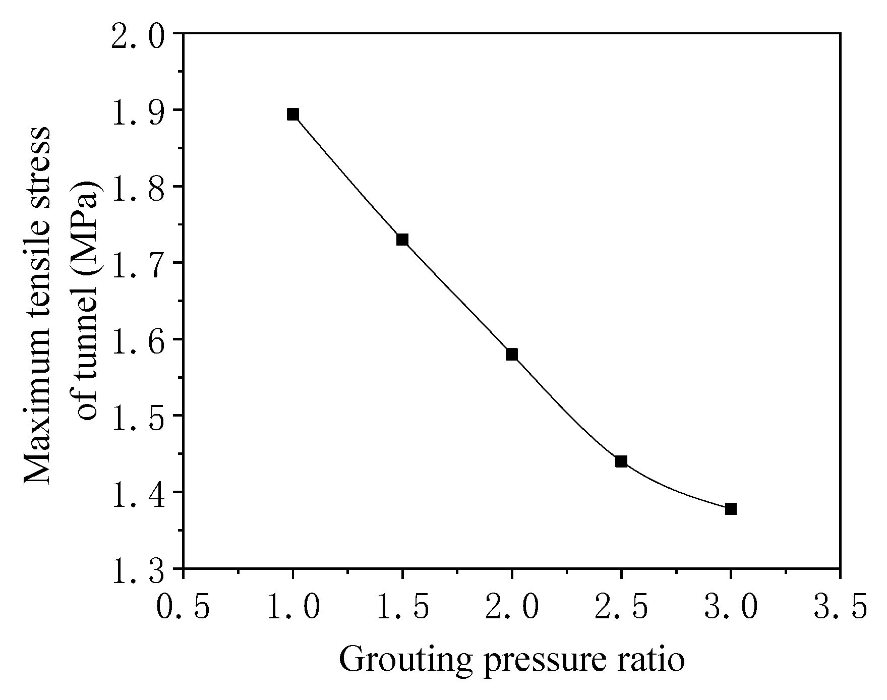
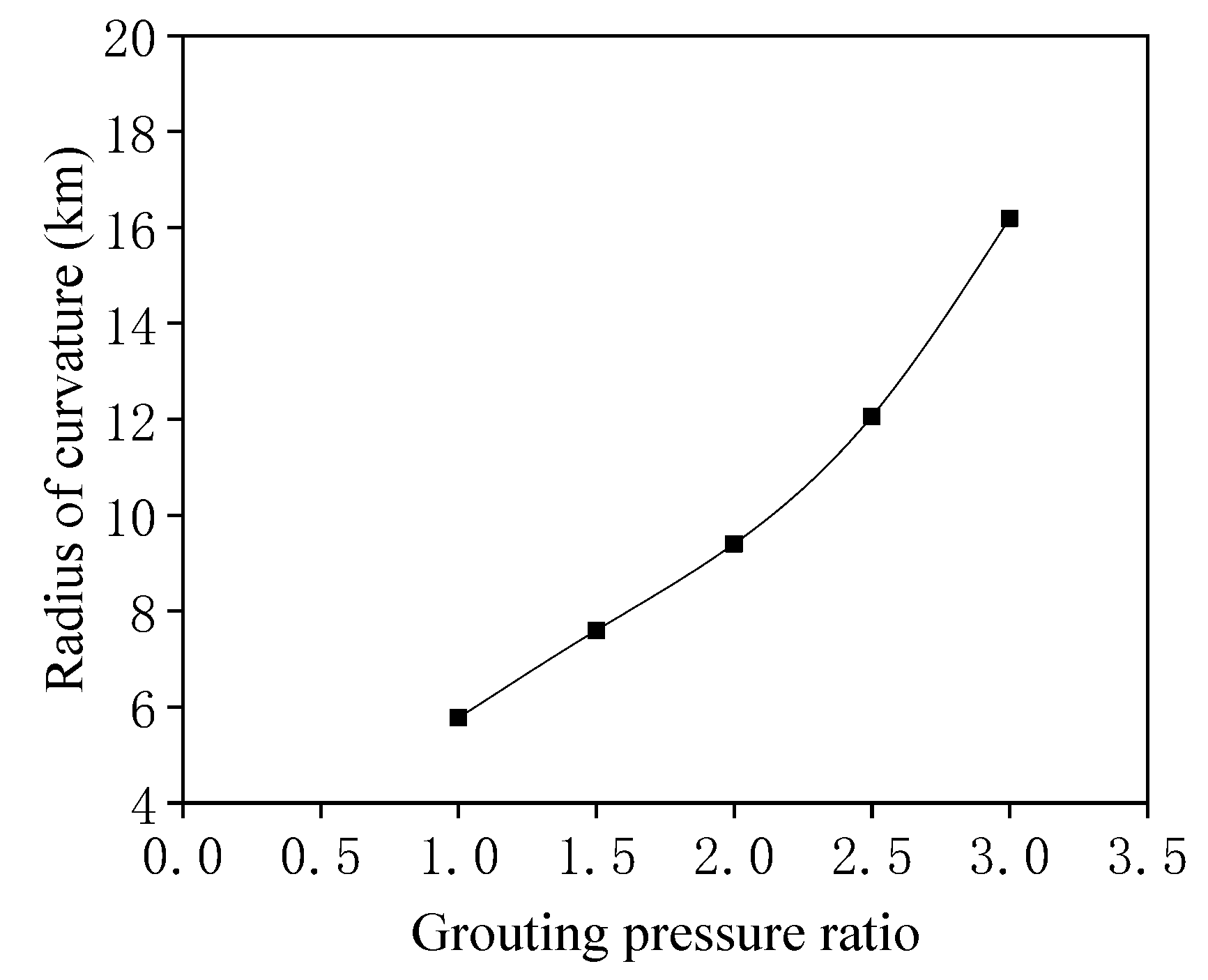
Comparing the curves of
Figure 24 and
Figure 25, it can be seen that with the increase in grouting pressure ratio, the tensile stress of the tunnel decreases, while the radius of curvature of the tunnel increases, and the curves are nonlinear. When the grouting pressure ratios are 1, 1.5, 2, 2.5 and 3, respectively, the maximum tensile stresses of the tunnel are 1.894 MPa, 1.73 MPa, 1.58 MPa, 1.44 MPa and 1.378 MPa, respectively. Compared to the tensile stress of the tunnel with the grouting pressure ratio of 1, the tensile stresses of the tunnel are reduced by 8.7%, 16.6%, 24.0% and 27.2%, respectively, for the grouting pressure ratios of 1.5, 2, 2.5 and 3.
The above results show that the proposed method of segmented pressure has a significant effect on reducing the uneven subsidence and the stress of the tunnel. The greater the grouting pressure ratio is, the smaller the longitudinal subsidence difference of the tunnel is, the smaller the maximum tensile stress is. At the same time, combined with the above analysis, with the increase in grouting pressure ratio, the percentage of settlement and stress reduction gradually decreases, and the visible effect gradually decreases. Therefore, it is suggested that the grouting pressure ratio should not exceed 3.
8. Conclusions
Based on the engineering background of a double-line shield tunnel undercrossing an existing foundation pit in a section of Changsha Metro Line 6, the deformation and mechanical characteristics of the foundation pit structure and the tunnel itself induced by the shield tunnel undercrossing the existing foundation pit as well as the influence of grouting pressure on the foundation pit structure and the tunnel itself are explored by numerical simulation. In addition, the method of segmented pressure is proposed, and the influence of segmented pressure on longitudinal displacement difference, tensile stress and radius of curvature of the tunnel is analyzed. The main conclusions are as follows:
Comparing the numerical simulation and monitoring data of ground surface subsidence, the maximum error between the numerical simulation and the monitoring data is 5.44%, so the numerical model is considered reliable.
When the tunnel undercrosses the existing foundation pit, uneven subsidence and greater stress of the foundation pit structure are produced: (1) The maximum vertical subsidence of the retaining pile is 3.76 mm. (2) The maximum vertical displacement of the anchor is 10.33 mm, and uneven subsidence occurs, resulting in deflection, which produces greater additional stress, and the tensile stress is increased by 32.4%. (3) The maximum subsidence difference of the foundation pit raft is 3.17 mm, and the warping deformation is produced with the shape of an “arch with upward warping of four corners”. Therefore, the shield tunnel will have a greater impact on the existing foundation pit. In the actual construction process, special attention should be paid to the hazards caused by the shield construction.
In the process of tunnel excavation, uneven subsidence of the tunnel occurs along the longitudinal direction, where large and small subsidences are located at the outside and underpart of the foundation pit, respectively. The maximum and minimum values are 11.15 mm and 2.13 mm, respectively, and the maximum subsidence difference is 9.02 mm.
Increasing the grouting pressure can significantly improve the longitudinal uneven subsidence and stress state of the foundation pit structure and tunnel itself, but it will damage the soil and segments when it is too high, so it is recommended that the grouting pressure should be less than 300 kPa.
Segmented pressure can reduce the longitudinal subsidence difference of the tunnel by 47.2% and the maximum tensile stress by 27.2%. It can be seen that segmented pressure can significantly reduce the uneven subsidence of the tunnel and improve the tunnel stress condition.
In today’s increasingly saturated state of ground space, shield tunnel construction and underground space development have become the mainstream trend, especially in cities with dense engineering buildings, and it is inevitable to encounter a variety of existing engineering structures. According to the research results, there is a larger interaction between shield tunnel construction and existing structures. It is suggested that engineers and designers should not only consider the stress and deformation of the structure but also pay attention to the reaction of the project itself. The deformation and stress of the structure and itself can be improved by strengthening the foundation pit supporting structure system or selecting appropriate shield construction parameters and methods (such as appropriate grouting pressure or segmented pressure).
However, this paper has some limitations, mainly focusing on the discovery of the interaction law and only exploring the influence of grouting pressure on excavation pressure. The influence law of shield tail clearance and other tunneling parameters have not been studied. At the same time, the grouting layer is simulated by equivalent layers. The relevant parameters have not been obtained through experiments, which will lead to certain errors. In the future, we will continue to promote the work, comprehensively explore the influence law of shield parameters and obtain relevant parameters in combination with experiments. At the same time, the methods and technologies to ensure the safe tunneling of shield tunnel under special conditions are deeply explored.


