
Deformation Characteristics of Soil Layers and Diaphragm Walls during Deep Foundation Pit Excavation: Simulation Verification and Parameter Analysis


Abstract
:1. Introduction
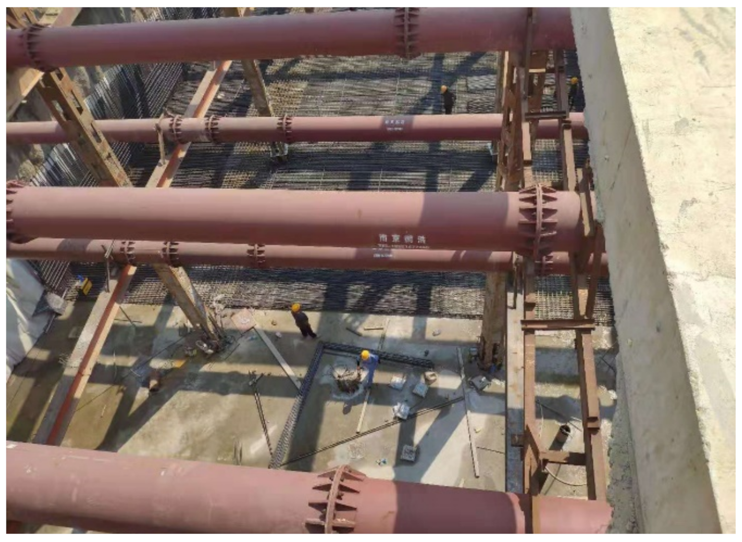
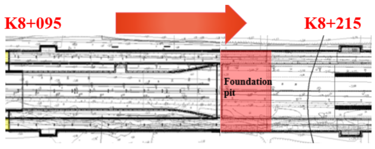
2. Project Profile
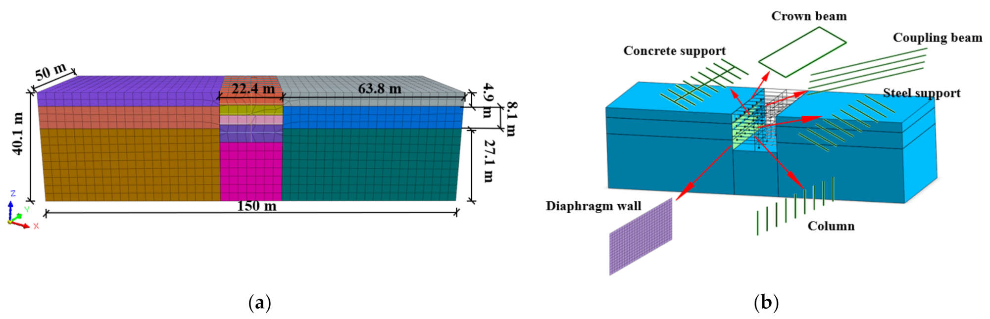
3. Numerical Models
3.1. Soil Model Selection
3.2. Basic Assumptions of Calculation
3.3. Material Parameter Setting
3.4. Structural Unit Selection
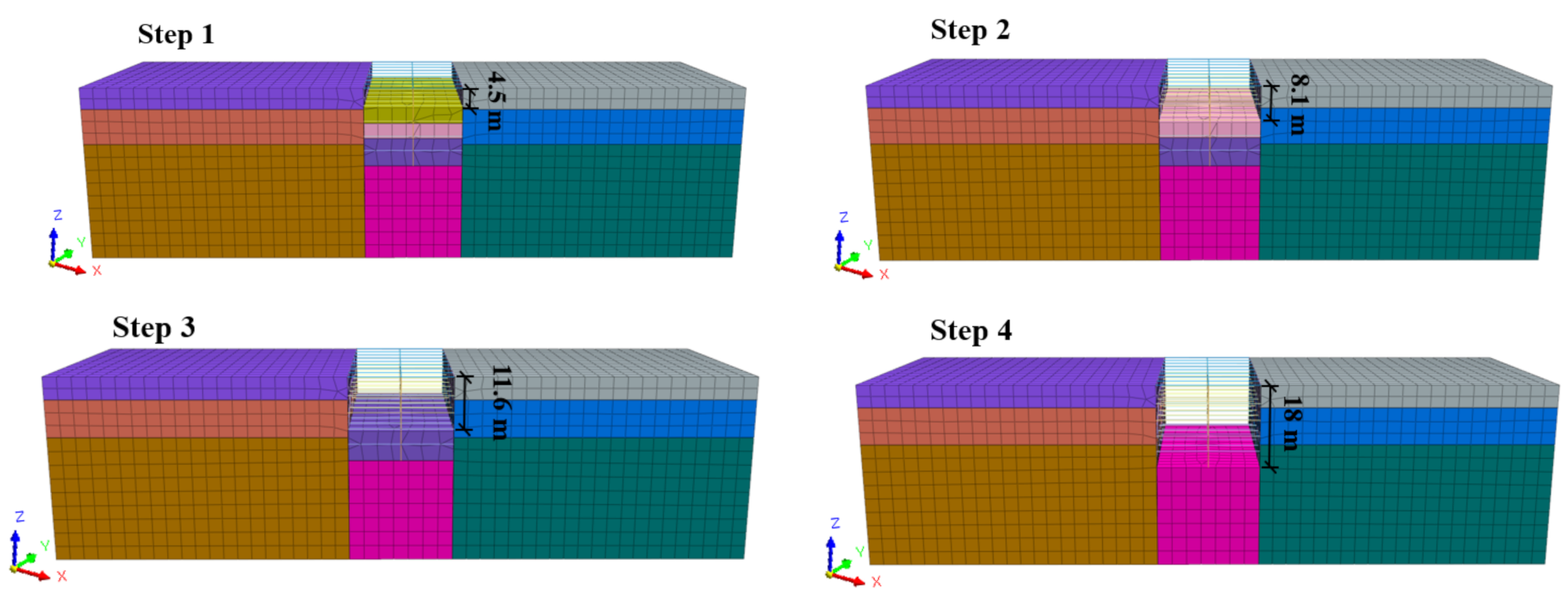
3.5. Process Simulation of Construction
4. Results and Discussion
4.1. Simulation Reliability Verification
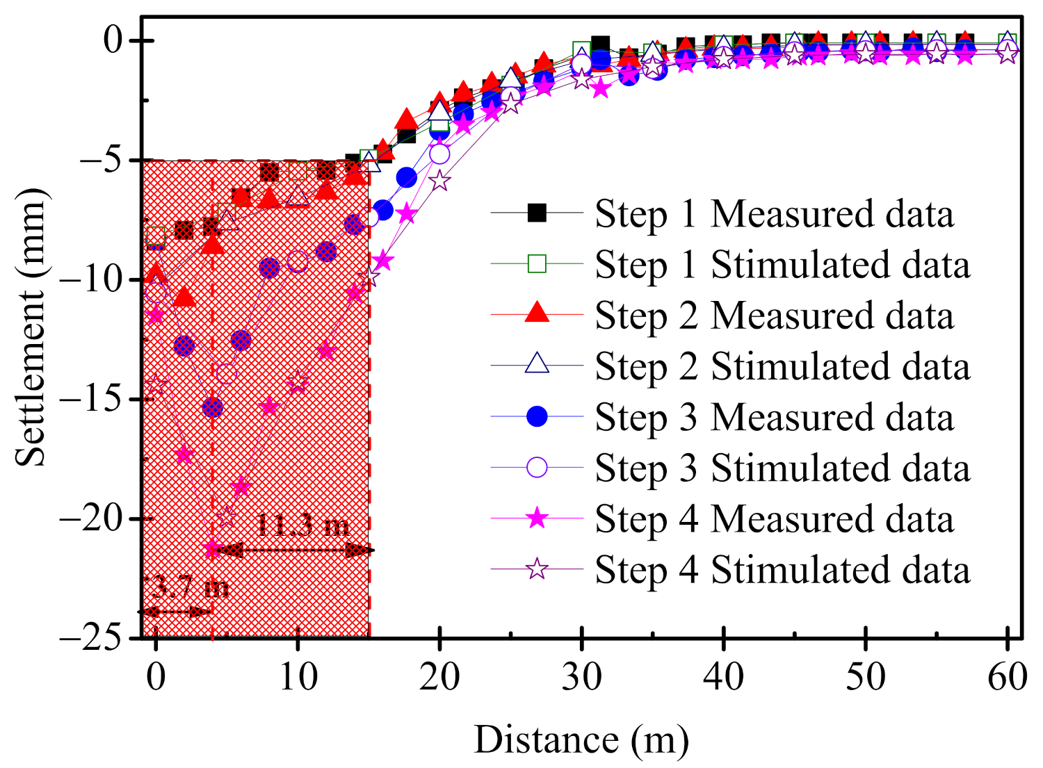
4.1.1. Ground Settlement
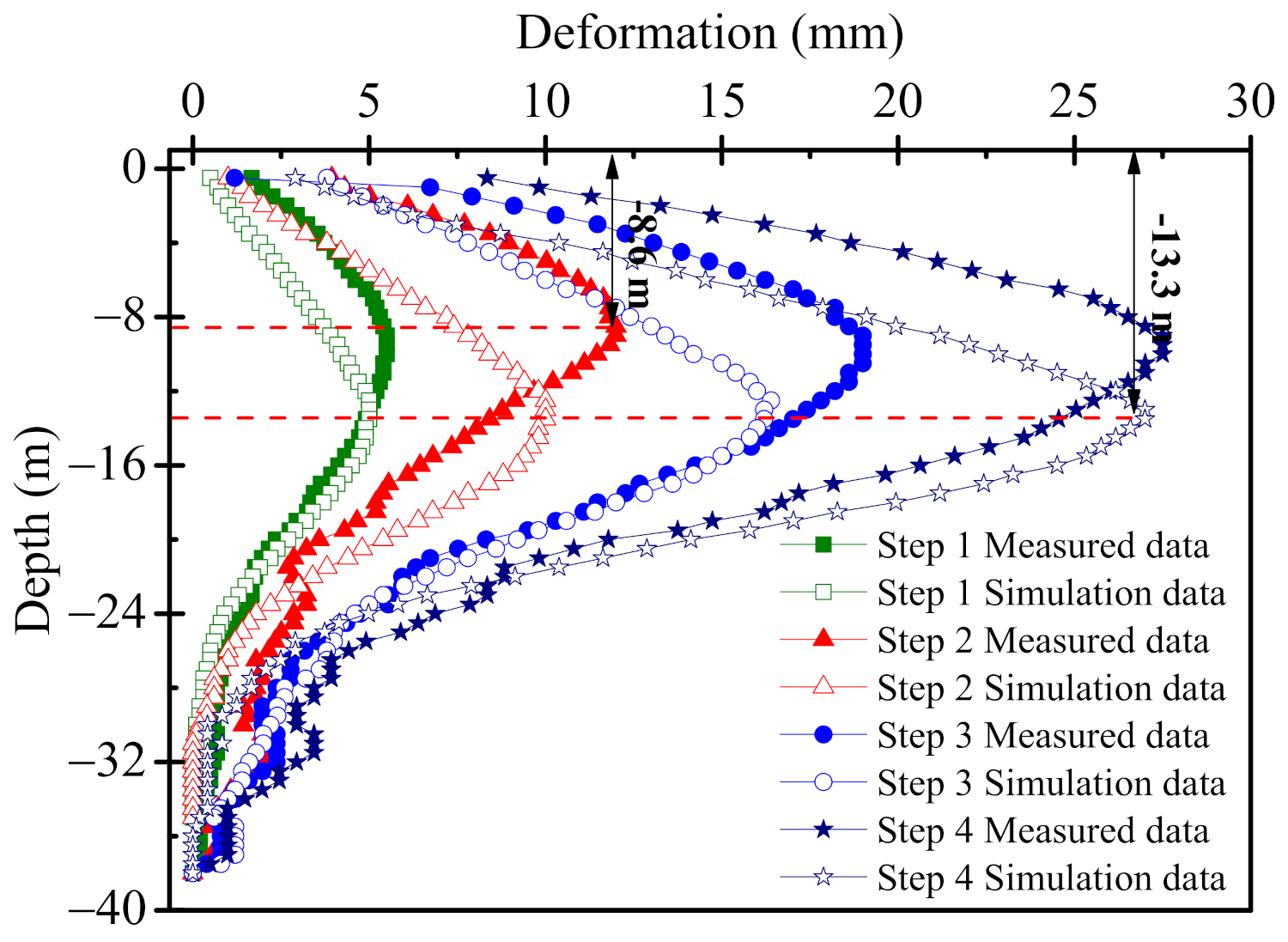
4.1.2. Horizontal Displacement of Diaphragm Wall
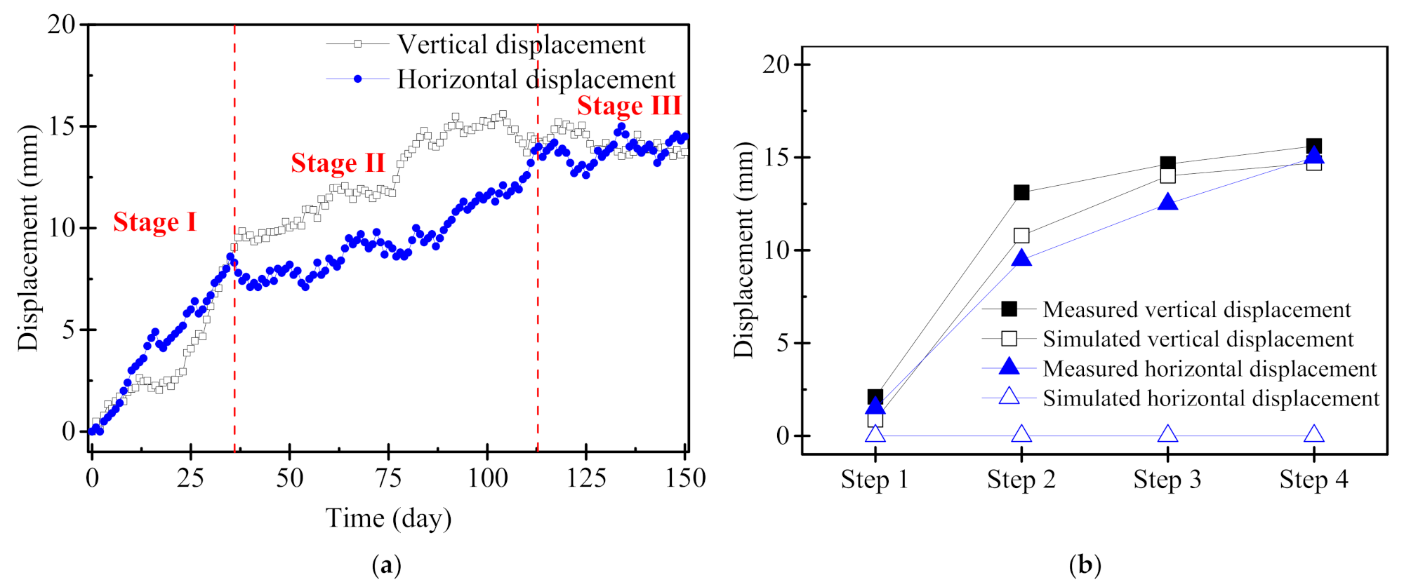
4.1.3. Crown Beam Displacement
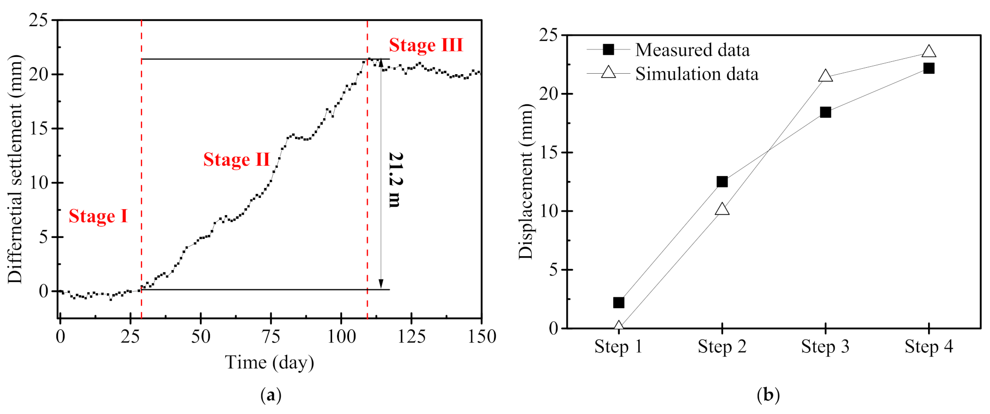
4.1.4. Column Settlement
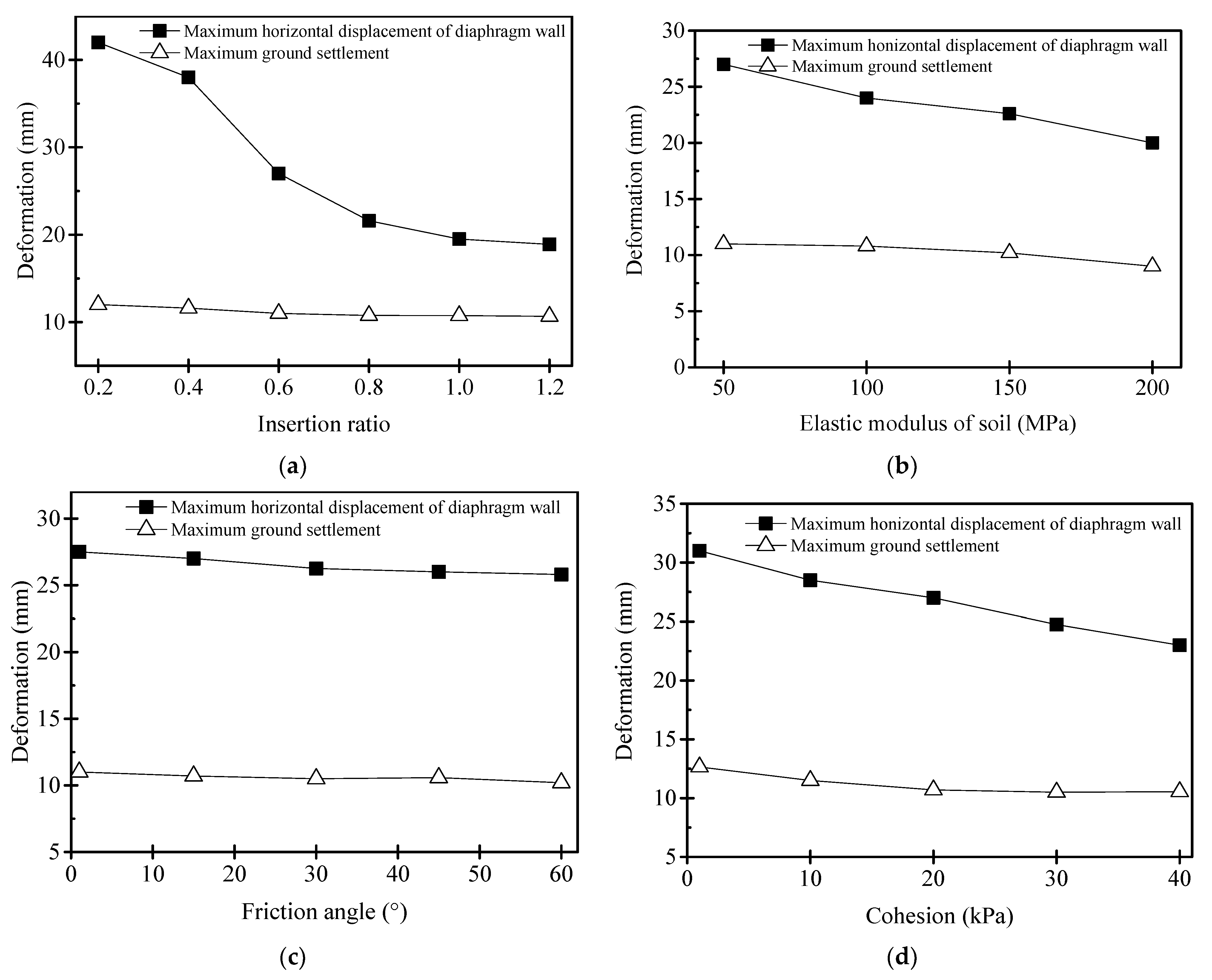
4.2. Sensitivity Analysis
4.2.1. Insertion Ratio of Diaphragm Wall
4.2.2. Elastic Modulus of Soil
4.2.3. Internal Friction Angle
4.2.4. Cohesion of Soil
4.3. Discussion
5. Conclusions
- Numerical calculations using MIDAS can fit the measured data well. This paper provides experience for similar future projects related to the study of the support structure, the surface settlement around the foundation pit, and the resistance to the uplift at the bottom of the foundation pit. With the continuous excavation of the foundation pit, the maximum horizontal displacement and maximum land subsidence of the underground diaphragm wall also increase. After the foundation pit’s excavation is completed, the maximum horizontal displacement of the underground diaphragm wall is 9.45 mm, and the maximum surface settlement is 21.25 mm. The displacement of the crown beam is divided into three stages; the first stage’s displacement exceeds 75% of the total displacement. The uplift at the bottom of the foundation pit is reflected by the deformation of the column, and the largest pit bottom uplift is 21.46 mm.
- Considering the elastic modulus, cohesion, internal friction angle, and insertion ratio of the diaphragm wall, the sensitivity analysis is conducted based on the maximum settlement of the diaphragm wall and the surface. This paper comprehensively considers the cost and risk, and provides an idea for selecting the optimal insertion ratio for the foundation pit of the underground diaphragm wall as the supporting structure. The cohesion, internal friction angle, elastic modulus, and insertion ratio have negative effects on the deformation of foundation pits and diaphragm walls. Among them, the effects of the insertion ratio and elastic modulus, in terms of limiting the maximum displacement of the foundation pit and the diaphragm wall, are better than the effects of the cohesion and internal friction angle.
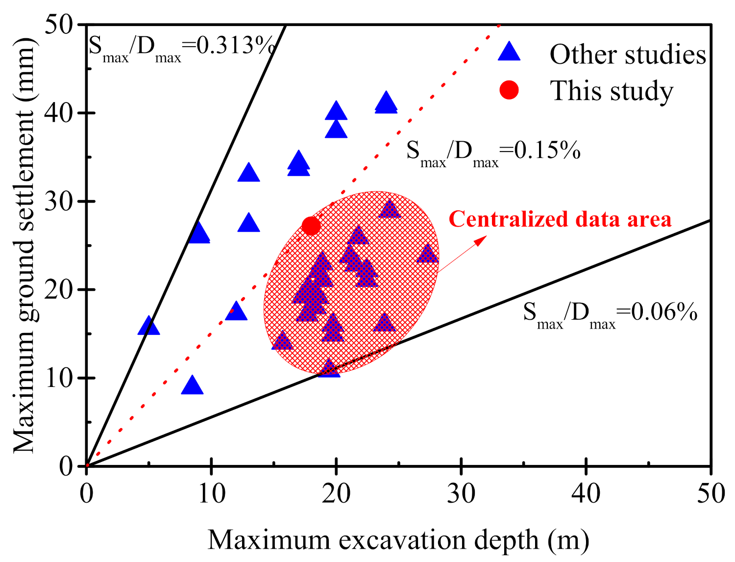
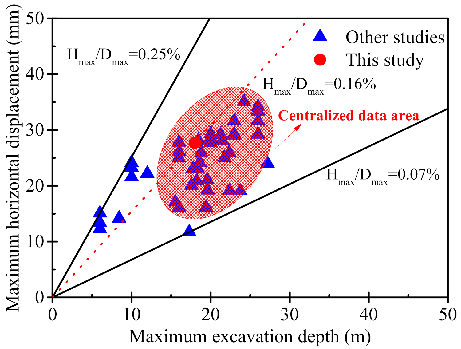
- Summarizing the research results of other scholars, the maximum land subsidence and maximum horizontal displacement of the supporting structure are positively correlated with the excavation depth. The ratio of the maximum surface settlement to the maximum excavation depth is 0.313–0.060%, and the ratio of the maximum horizontal displacement of the support structure to the maximum excavation depth is 0.07–0.25%. The research results summarized in this paper can be used as a means to assess the control risk of foundation pit excavation.
Author Contributions
Funding
Institutional Review Board Statement
Informed Consent Statement
Data Availability Statement
Conflicts of Interest
References
- Nguyen, T.S.; Likitlersuang, S. Reliability analysis of unsaturated soil slope stability under infiltration considering hydraulic and shear strength parameters. Bull. Eng. Geol. Environ. 2019, 78, 5727–5743. [Google Scholar] [CrossRef]
- Lin, H.-D.; Wang, W.-C.; Li, A.-J. Investigation of dilatancy angle effects on slope stability using the 3D finite element method strength reduction technique. Comput. Geotech. 2020, 118, 103295. [Google Scholar] [CrossRef]
- VandenBerge, D.R.; McGuire, M.P. Practical Use of Modified Hoek–Brown Criterion for Soil Slope Stability Analysis. Geotech. Geol. Eng. 2019, 37, 5441–5455. [Google Scholar] [CrossRef]
- Moormann, C. Analysis of Wall and Ground Movements Due to Deep Excavations in Soft Soil Based on a New Worldwide Database. Soils Found. 2004, 44, 87–98. [Google Scholar] [CrossRef] [Green Version]
- Wang, Z.W.; Ng, C.W.; Liu, G.B. Characteristics of wall deflections and ground surface settlements in Shanghai. Can. Geotech. J. 2005, 42, 1243–1254. [Google Scholar] [CrossRef]
- Kalatehjari, R.; Ali, N.M.M.; Kholghifard, M.; Hajihassani, M. The effects of method of generating circular slip surfaces on determining the critical slip surface by particle swarm optimization. Arab. J. Geosci. 2013, 7, 1529–1539. [Google Scholar] [CrossRef]
- Sedighi, H.M.; Bozorgmehri, A. Nonlinear vibration and adhesion instability of Casimir-induced nonlocal nanowires with the consideration of surface energy. J. Braz. Soc. Mech. Sci. Eng. 2017, 39, 427–442. [Google Scholar] [CrossRef]
- Lancellotta, R. Analytical solution of passive earth pressure. Géotechnique 2002, 52, 617–619. [Google Scholar] [CrossRef]
- Greco, V.R. Discussion of “Seismic active earth pressure behind a nonvertical retaining wall using pseudo-dynamic analysis”. Can. Geotech. J. 2008, 45, 1795–1797. [Google Scholar] [CrossRef]
- Gnanapragasam, N. Active earth pressure in cohesive soils with an inclined ground surface. Can. Geotech. J. 2000, 37, 171–177. [Google Scholar] [CrossRef]
- Xiang, G.J.; Yin, D. Application of artificial neural network for prediction of flow ability of soft soil subjected to vibrations. Geomech. Eng. 2021, 25, 395–403. [Google Scholar] [CrossRef]
- Das, A.K.; Deb, K. Response of Cylindrical Storage Tank Foundation Resting on Tensionless Stone Column-Improved Soil. Int. J. Geomech. 2017, 17, 04016035. [Google Scholar] [CrossRef]
- Zheng, G.; Yang, X.; Zhou, H.; Chai, J. Numerical modeling of progressive failure of rigid piles under embankment load. Can. Geotech. J. 2019, 56, 23–34. [Google Scholar] [CrossRef]
- Gnanendran, C.T.; Manivannan, G.; Lo, S.-C. Influence of using a creep, rate, or an elastoplastic model for predicting the behaviour of embankments on soft soils. Can. Geotech. J. 2006, 43, 134–154. [Google Scholar] [CrossRef]
- Zhang, L.; Wang, J.; Hu, X.; Zhou, J.; Zhao, M.; Zhang, J.; Bo, Y.; Huang, Y.; Zhang, Y. VOCs and PM concentrations in underground parking garages of the commercial center and high-rise residential buildings. Air Qual. Atmos. Health 2021, 14, 1117–1131. [Google Scholar] [CrossRef]
- Sun, H.; Chen, Y.; Zhang, J.; Kuang, T. Analytical investigation of tunnel deformation caused by circular foundation pit excavation. Comput. Geotech. 2019, 106, 193–198. [Google Scholar] [CrossRef]
- Liu, L.; Wu, R.; Congress, S.S.C.; Du, Q.; Cai, G.; Li, Z. Design optimization of the soil nail wall-retaining pile-anchor cable supporting system in a large-scale deep foundation pit. Acta Geotech. 2021, 16, 2251–2274. [Google Scholar] [CrossRef]
- Zhang, J.; Li, M.; Ke, L.; Yi, J. Distributions of lateral earth pressure behind rock-socketed circular diaphragm walls considering radial deflection. Comput. Geotech. 2021, 143, 104604. [Google Scholar] [CrossRef]
- Zhu, C.; Yan, Z.; Lin, Y.; Xiong, F.; Tao, Z. Design and Application of a Monitoring System for a Deep Railway Foundation Pit Project. IEEE Access 2019, 7, 107591–107601. [Google Scholar] [CrossRef]
- Sun, Y.; Xiao, H. Wall Displacement and Ground-Surface Settlement Caused by Pit-in-Pit Foundation Pit in Soft Clays. KSCE J. Civ. Eng. 2021, 25, 1262–1275. [Google Scholar] [CrossRef]
- Zhao, Z.; Zhu, Y.; Ye, S. Study on settlement deformation of high fill foundation in large thickness loess area. Arab. J. Geosci. 2021, 14, 1–12. [Google Scholar] [CrossRef]
- Finno, R.J.; Blackburn, J.T.; Roboski, J.F. Three-Dimensional Effects for Supported Excavations in Clay. J. Geotech. Geoenviron. Eng. 2007, 133, 30–36. [Google Scholar] [CrossRef] [Green Version]
- Lin, P.; Liu, P.; Ankit, G.; Singh, Y.J. Deformation Monitoring Analysis and Numerical Simulation in a Deep Foundation Pit. Soil Mech. Found. Eng. 2021, 58, 56–62. [Google Scholar] [CrossRef]
- Liang, J.J.; Wang, F.; Liu, Y.W.; Sun, X.Y. The Numerical Simulation and Deformation Analysis to the Deep Foundation Pit of Diaphragm Wall Based on Midas/GTS. Appl. Mech. Mater. 2015, 733, 456–459. [Google Scholar] [CrossRef]
- Wang, Z. Numerical Analysis of Deformation Control of Deep Foundation Pit in Ulanqab City. Geotech. Geol. Eng. 2021, 39, 5325–5337. [Google Scholar] [CrossRef]
- Li, W.; Fu, L.; Zhu, Z. Numerical simulation and land subsidence control for deep foundation pit dewatering of Longyang Road Station on Shanghai Metro Line 18. J. Groundw. Sci. Eng. 2019, 7, 133–144. [Google Scholar]
- Liu, Y.L. Numerical Analysis of the Deformation Law of Deep Foundation Pit of Subway Station by FLAC3D. Adv. Mater. Res. 2014, 915, 62–67. [Google Scholar] [CrossRef]
- Cui, X.; Ye, M.; Zhuang, Y. Performance of a foundation pit supported by bored piles and steel struts: A case study. Soils Found. 2018, 58, 1016–1027. [Google Scholar] [CrossRef]
- Liu, S.; Li, H.; Tong, L. Simulation of pile cap contribution to the lateral pile performance due to adjacent excavation. Acta Geotech. 2021, 16, 1895–1907. [Google Scholar] [CrossRef]
- Bai, J.; Chen, H.; Jia, J.; Sun, B.; Jin, S. New lateral load distribution pattern for seismic design of deteriorating shear buildings considering soil-structure interaction. Soil Dyn. Earthq. Eng. 2020, 139, 106344. [Google Scholar] [CrossRef]
- Buchholtz, E.A.; Yozgyur, Z.M.; Feldman, A.; Weaver, A.A.; Gaudin, T.J. The therian sternum at the lateral somitic frontier: Evolution of a composite structure. J. Zool. 2021, 315, 19–28. [Google Scholar] [CrossRef]
- Naseri, S.; Bahrani, N. Design of Initial Shotcrete Lining for a Mine Shaft Using Two-Dimensional Finite Element Models Considering Excavation Advance Rate. Geotech. Geol. Eng. 2021, 39, 4709–4732. [Google Scholar] [CrossRef]
- Liu, X.; El Naggar, M.H.; Wang, K.; Tu, Y.; Qiu, X. Simplified model of defective pile-soil interaction considering three-dimensional effect and application to integrity testing. Comput. Geotech. 2021, 132, 103986. [Google Scholar] [CrossRef]
- Kechidi, S.; Colaço, A.; Costa, P.A.; Castro, J.M.; Marques, M. Modelling of soil-structure interaction in OpenSees: A practical approach for performance-based seismic design. Structures 2021, 30, 75–88. [Google Scholar] [CrossRef]
- Yang, T.L.; Yan, X.X.; Wang, H.M.; Huang, X.L.; Zhan, G.H. Comprehensive experimental study on prevention of land subsidence caused by dewatering in deep foundation pit with hanging waterproof curtain. Proc. Int. Assoc. Hydrol. Sci. 2015, 372, 1–5. [Google Scholar] [CrossRef] [Green Version]
- Gerczuk, P.Z.; Kloner, R.A. An update on cardioprotection, a review of the latest adjunctive therapies to limit myocardial infarc-tion size in clinical trials. J. Am. Coll. Cardiol. 2012, 59, 969–978. [Google Scholar] [CrossRef] [PubMed] [Green Version]
- Ding, Z.; Jin, J.; Han, T.-C. Analysis of the zoning excavation monitoring data of a narrow and deep foundation pit in a soft soil area. J. Geophys. Eng. 2018, 15, 1231–1241. [Google Scholar] [CrossRef] [Green Version]
- Yang, J.; Kong, D. Deformation of deep and large foundation pit in soft soil of Fuzhou Subway. Arab. J. Geosci. 2020, 13, 1–10. [Google Scholar] [CrossRef]


| Soil Layer Name | Thickness of Soil Layer (m) | Density (g/cm3) | Cohesion (kPa) | Friction Angle (°) |
|---|---|---|---|---|
| Miscellaneous fill | 4.90 | 1.88 | 10.00 | 8.00 |
| Silt | 8.10 | 1.89 | 26.80 | 14.50 |
| Silty clay | 27.10 | 1.92 | 34.80 | 16.30 |
| Geometric Properties | Density (g/cm3) | Elastic Modulus (GPa) | |
|---|---|---|---|
| Concrete support | 800 mm × 800 mm | 2.4 | 30 |
| Steel support | D 1 = 600 mm or 800 mm t 2 = 16 mm | 7.8 | 210 |
| Diaphragm wall | Thickness = 1000 mm | 2.4 | 30 |
| Construction Condition | Supporting Structure | Excavation |
|---|---|---|
| Step 1 | Activate the crown beam and first support | Carry out the first excavation located at 4.0 m below the surface |
| Step 2 | Activate the second support | Carry out the second excavation located at 8.1 m below the surface |
| Step 3 | Activate the third support | Carry out the third excavation located at 11.6 m below the surface |
| Step 4 | Activate the fourth support | Carry out the fourth excavation located at 18.0 m below the surface |
Publisher’s Note: MDPI stays neutral with regard to jurisdictional claims in published maps and institutional affiliations. |
© 2022 by the authors. Licensee MDPI, Basel, Switzerland. This article is an open access article distributed under the terms and conditions of the Creative Commons Attribution (CC BY) license (https://creativecommons.org/licenses/by/4.0/).
Share and Cite
Feng, Z.; Xu, Q.; Xu, X.; Tang, Q.; Li, X.; Liao, X. Deformation Characteristics of Soil Layers and Diaphragm Walls during Deep Foundation Pit Excavation: Simulation Verification and Parameter Analysis. Symmetry 2022, 14, 254. https://doi.org/10.3390/sym14020254
Feng Z, Xu Q, Xu X, Tang Q, Li X, Liao X. Deformation Characteristics of Soil Layers and Diaphragm Walls during Deep Foundation Pit Excavation: Simulation Verification and Parameter Analysis. Symmetry. 2022; 14(2):254. https://doi.org/10.3390/sym14020254
Chicago/Turabian StyleFeng, Zheyuan, Qi Xu, Xiangyang Xu, Qiang Tang, Xuedong Li, and Xin Liao. 2022. "Deformation Characteristics of Soil Layers and Diaphragm Walls during Deep Foundation Pit Excavation: Simulation Verification and Parameter Analysis" Symmetry 14, no. 2: 254. https://doi.org/10.3390/sym14020254