
Effects of Foundation Excavation on Metro Tunnels at Different Locations and Performance of Corresponding Reinforcement Measures: A Case of Shenzhen Metro Line 11, China
Abstract
:1. Introduction
2. Project Overview
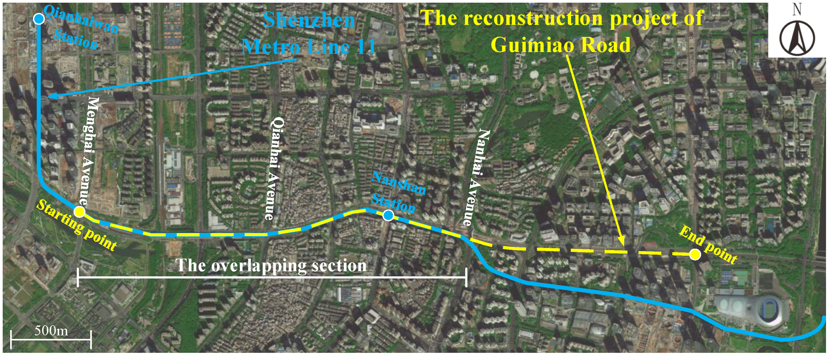
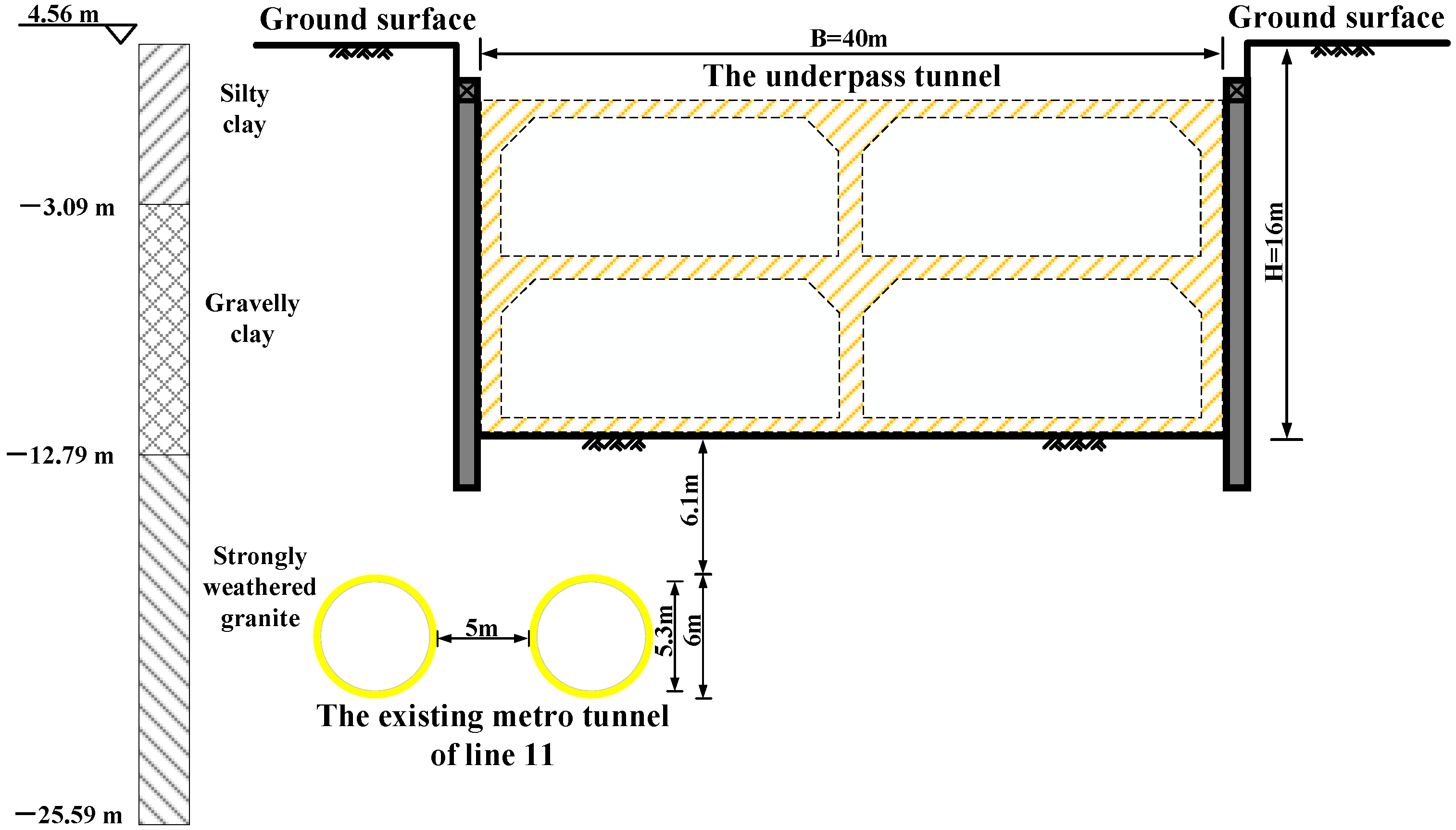
2.1. Project Introduction
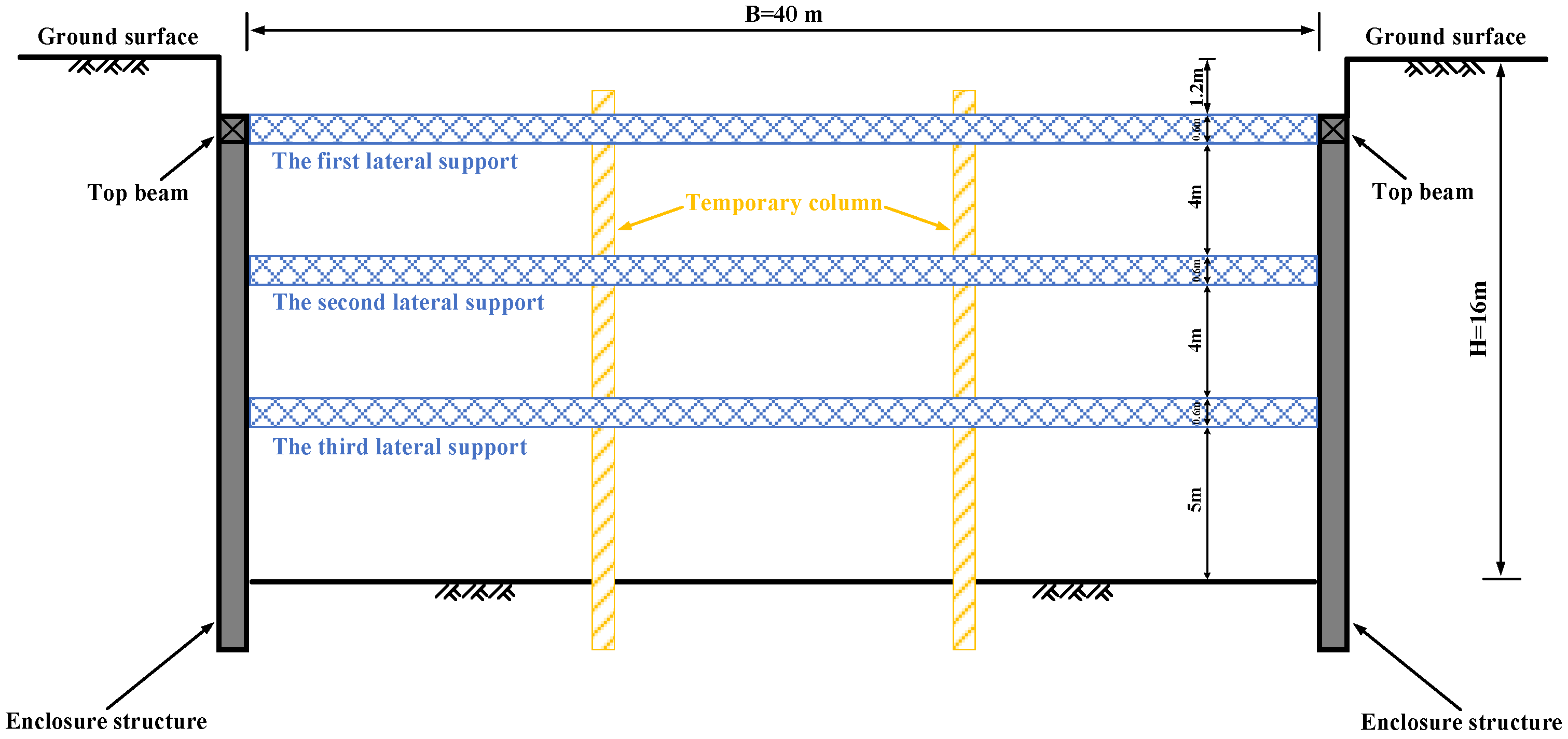
2.2. Foundation Pit Enclosure Structure and Excavation Scheme
3. Numerical Simulation of Overlapping Foundation Pit Excavation
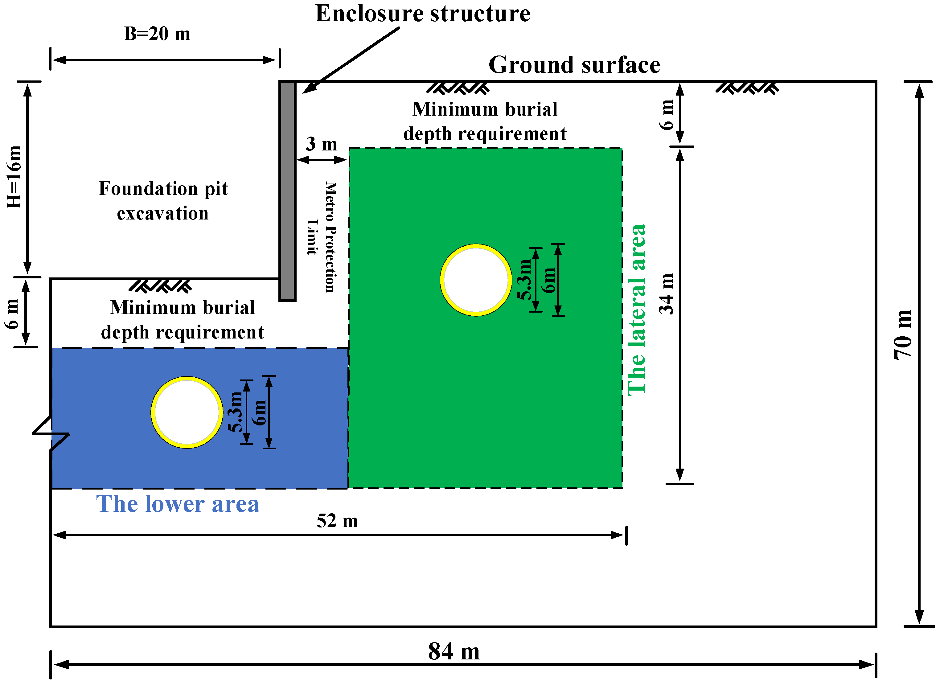
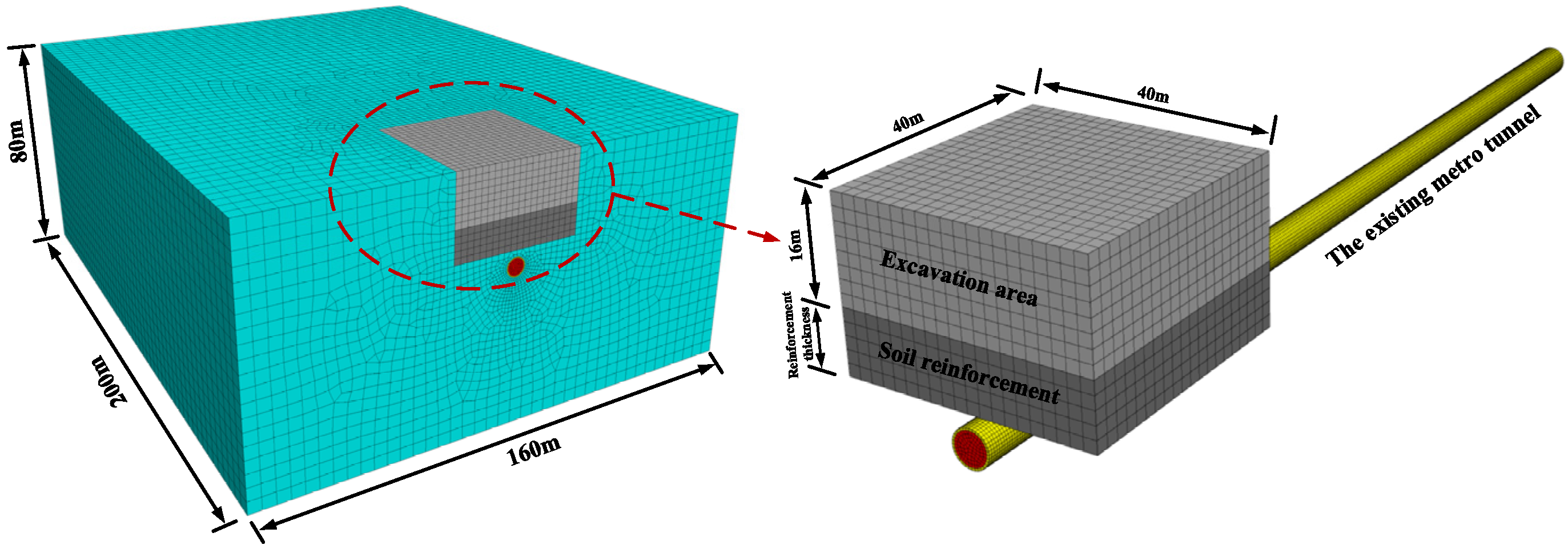
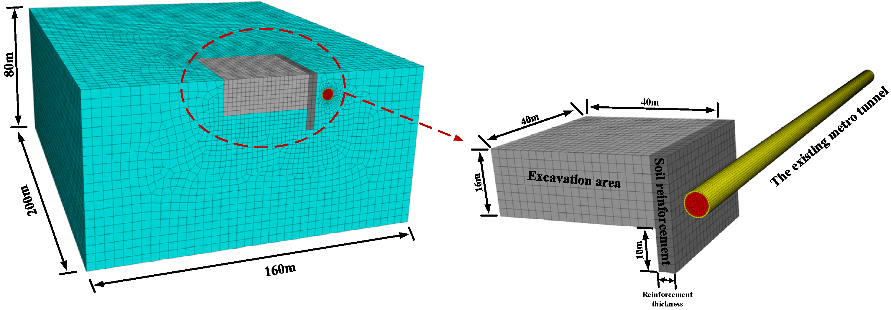
3.1. Computation Model and Boundary Conditions
3.2. Constitutive Model and Model Parameters
3.3. Numerical Modeling Procedure
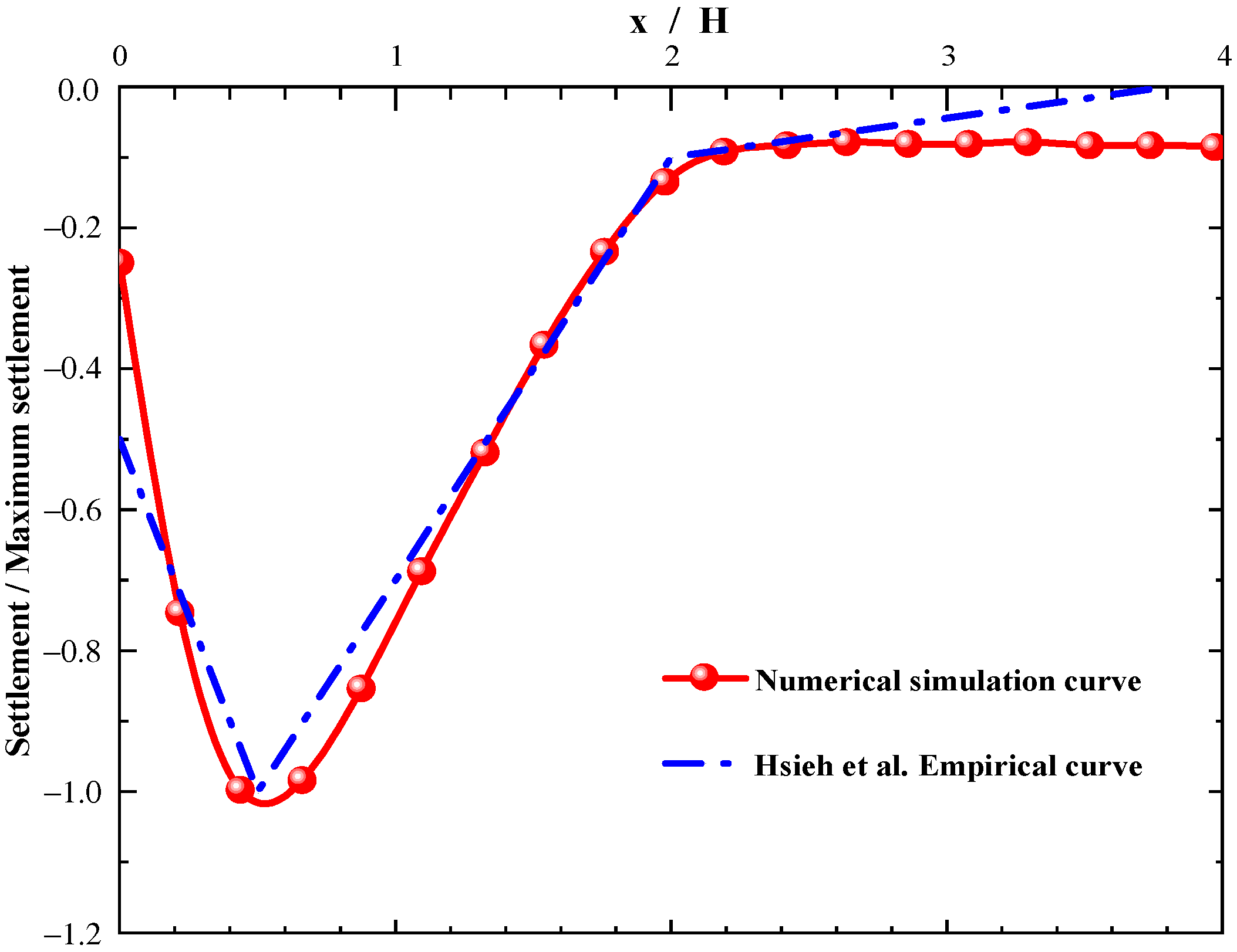
3.4. Validation of Numerical Models
3.5. Results and Analysis
4. Discussion on the Selection and Performance of Reinforcement Measures
4.1. Analysis of Reinforcement Measures in the Lower Area
4.2. Analysis of Reinforcement Measures in the Lateral Area
5. Conclusions
- (1)
- In this paper, a numerical simulation method is used to analyze the influence of overlapping foundation pit excavation on adjacent tunnels. The deformation characteristics of adjacent tunnels at different locations caused by foundation pit excavation are studied, and the soil reinforcement measures applicable to tunnels at different locations are proposed, respectively. Based on the above analyses, the following conclusions were drawn:
- (2)
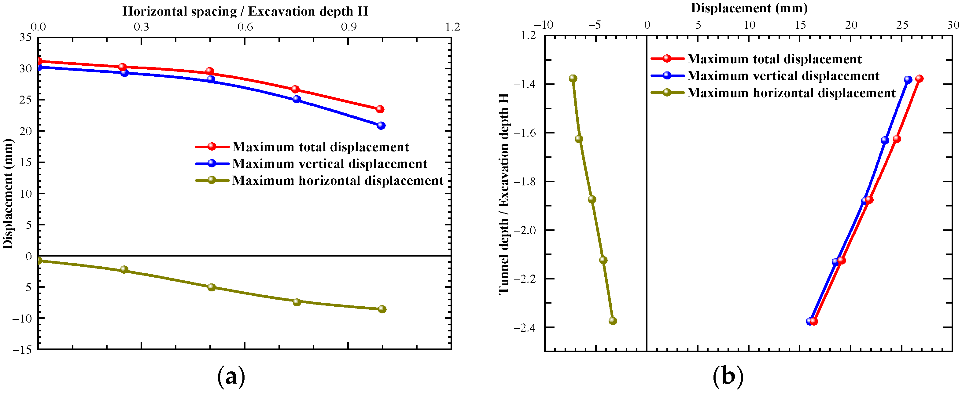
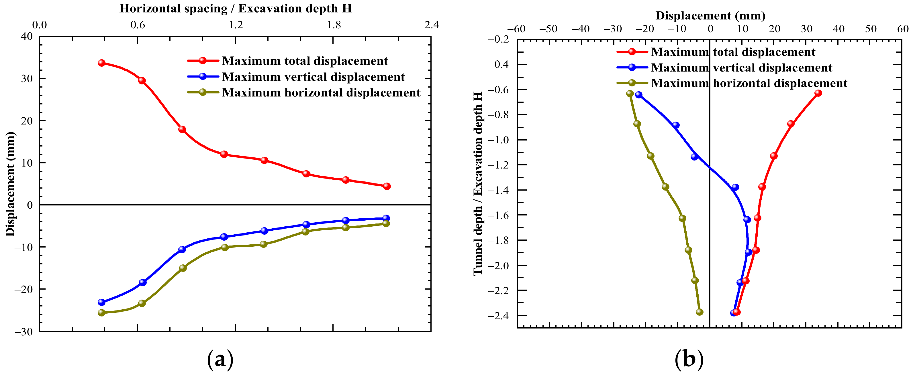
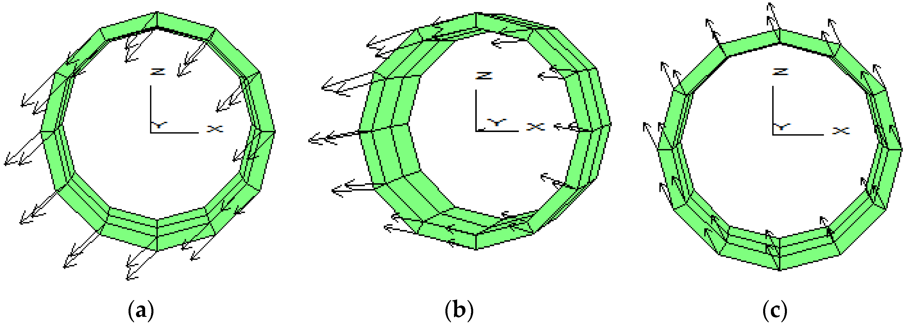
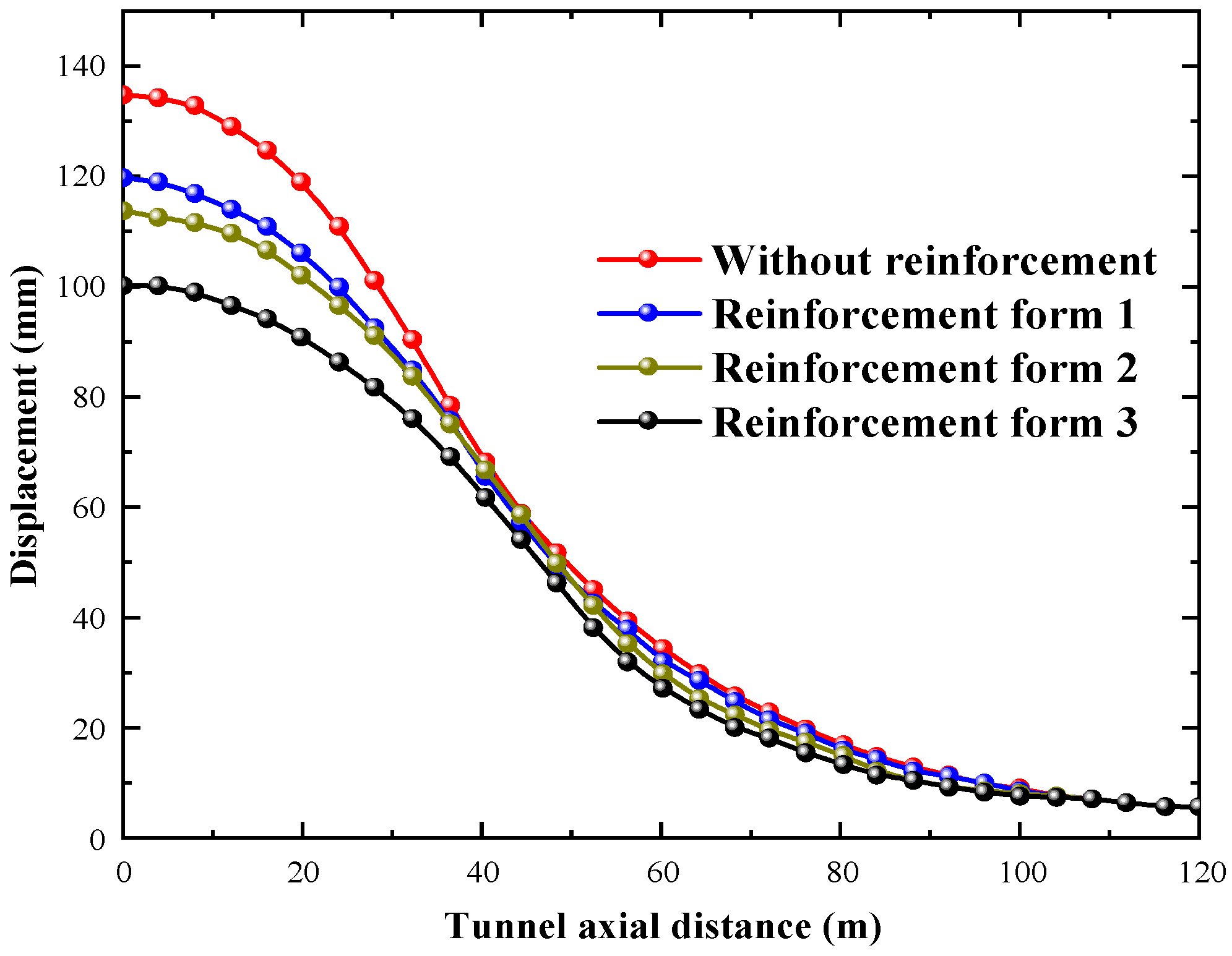
- The deformation characteristics of adjacent tunnels caused by foundation pit excavation can be divided into three areas: the settlement zone, the transition zone, and the uplift zone. Firstly, the settlement zone is mainly located in the lateral area of the foundation pit and in a certain shallow buried stratum below the ground surface. The displacement of the tunnel in the settlement zone is relatively significant in both the vertical and horizontal directions. Secondly, the transition zone is mainly located within a certain range below the settlement zone. The displacement of the tunnel in the transition zone is small in the vertical direction but large in the horizontal direction. Finally, the uplift zone is mainly located in the zone below the foundation pit. The displacement of the tunnel in the uplift zone is large in vertical direction, but small in horizontal direction.
- (3)
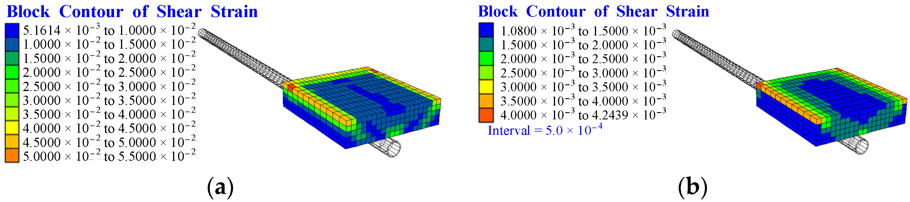
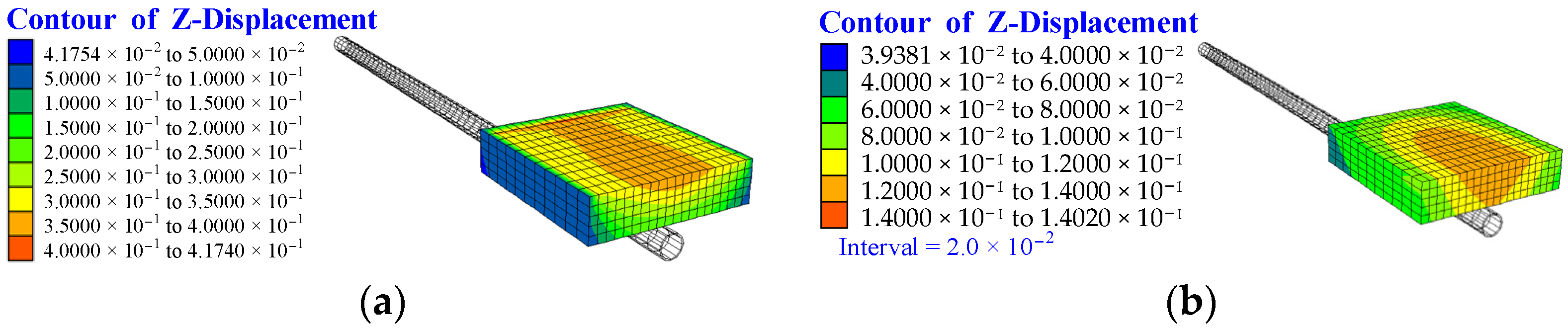
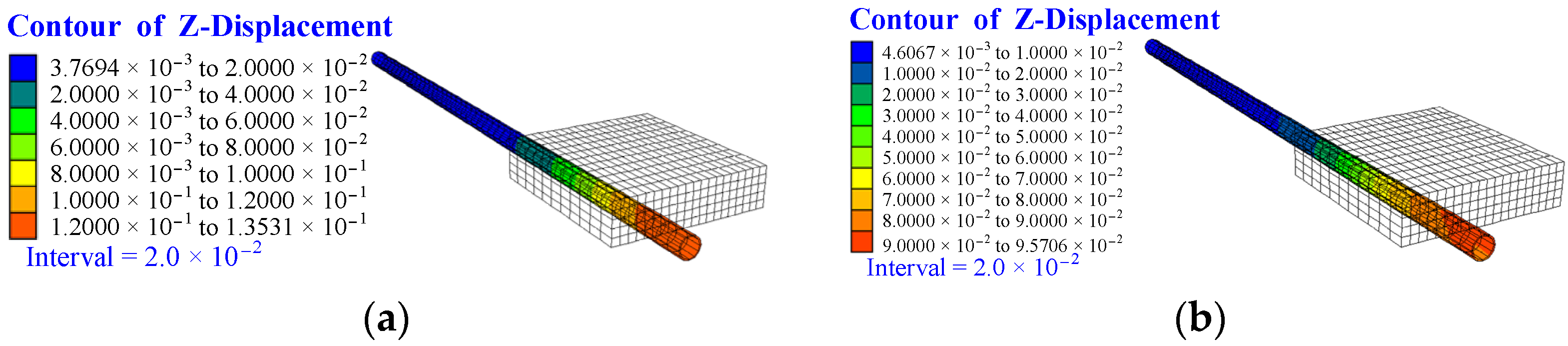
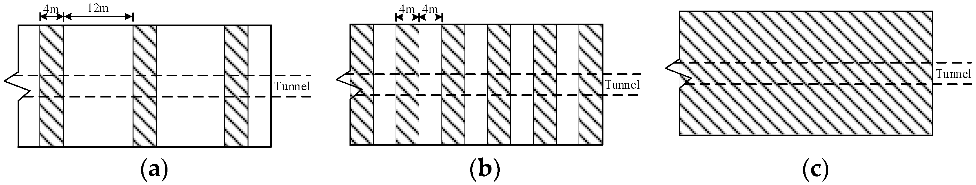
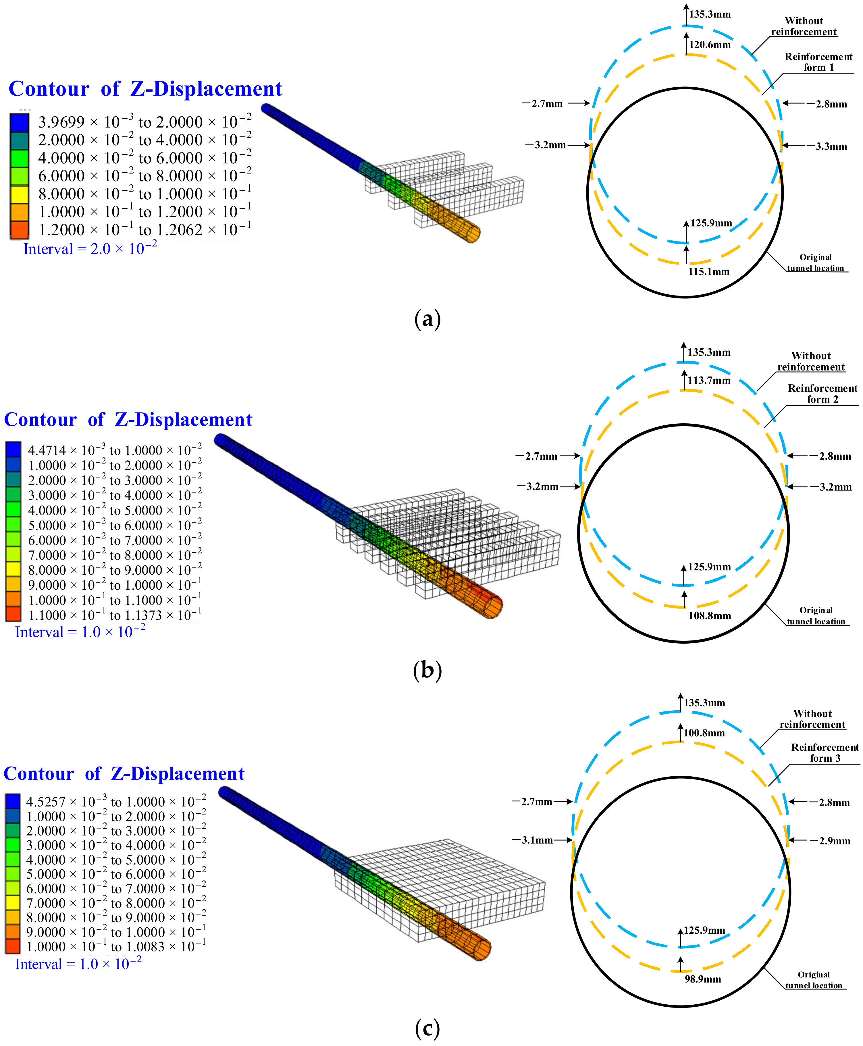
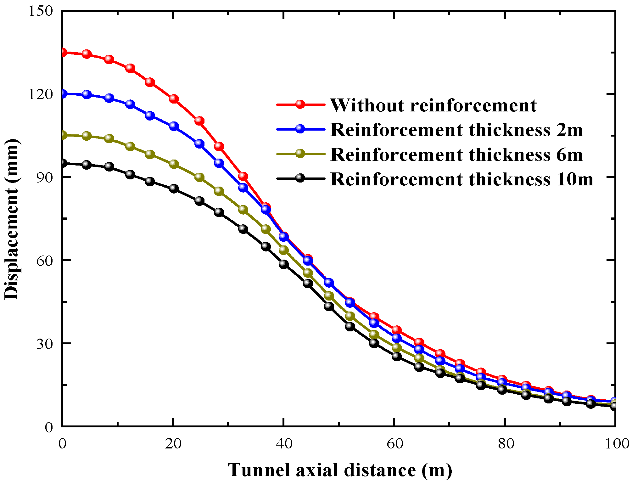
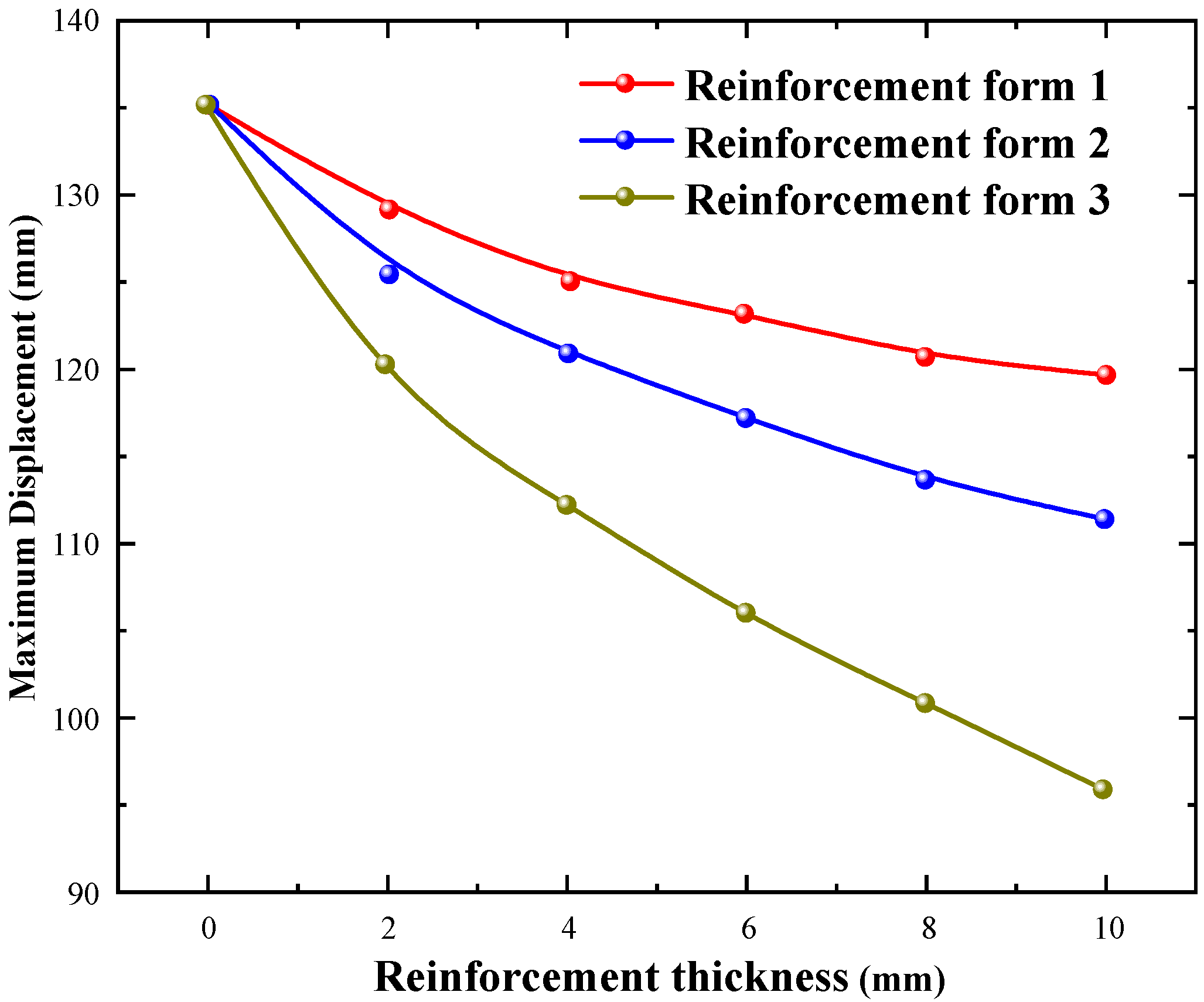
- In the lower area, the reinforced soil shows a strong integrity, which makes the stress and strain transfer more uniform. The relative tensile deformation in the shape of “vertical ellipse” of the tunnel section is effectively controlled. Moreover, the integrity of soil is stronger under full-area reinforcement, and increasing the thickness of reinforcement can reduce tunnel deformation more effectively. When the reinforcement thickness is increased from 2 m to 10 m, the maximum vertical displacement of the tunnel is reduced by 21.5%. However, the integrity is weaker under the two kinds of strip reinforcement, and increasing the thickness is ineffective in reducing tunnel deformation. When the reinforcement thickness is increased from 2 m to 10 m, the maximum vertical displacement of the tunnel is only reduced by 11.0% and 6.9%, respectively.
- (4)
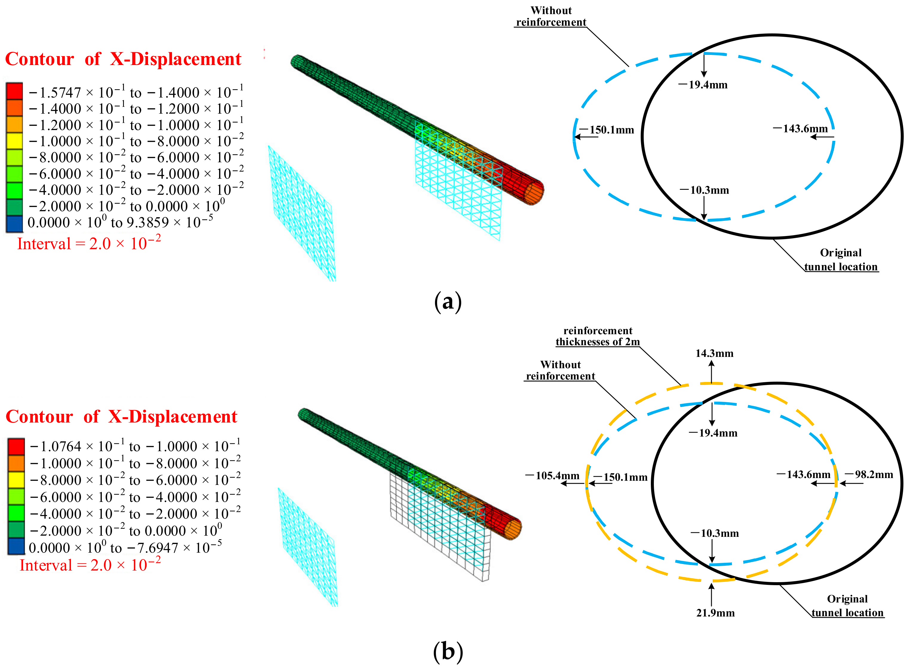
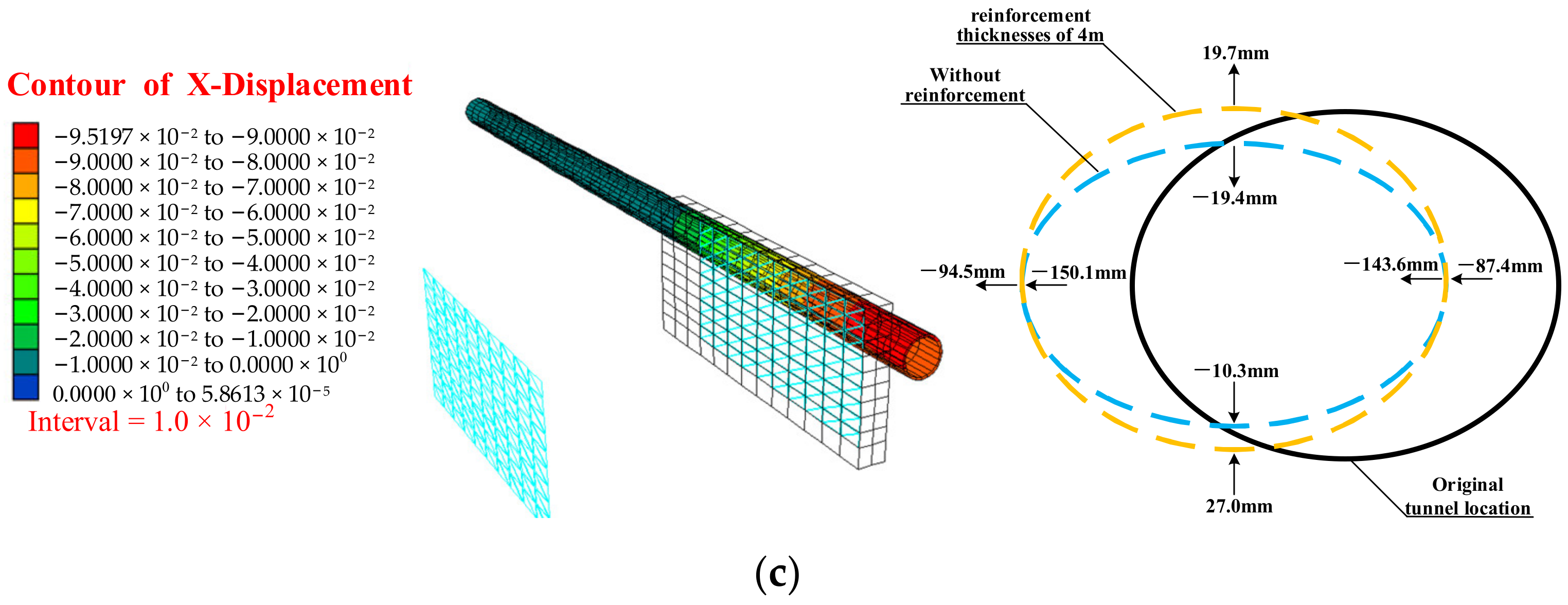
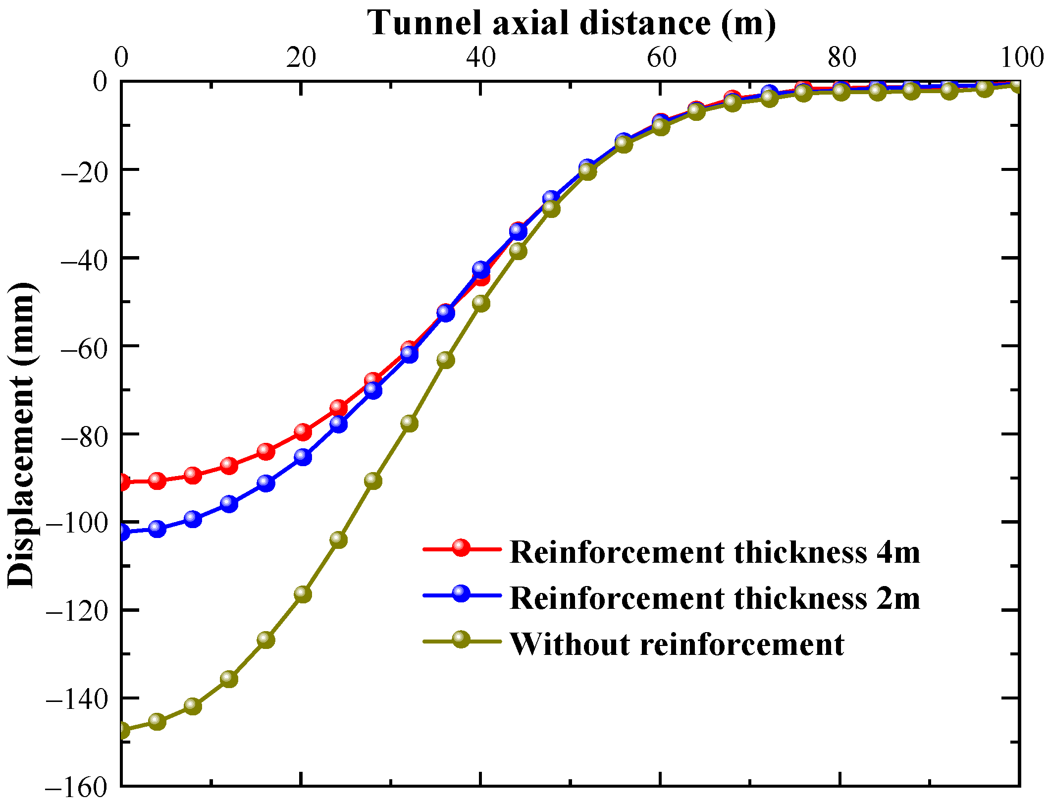
- In the lateral area, the reinforced soil has a similar effect as the reinforced soil in the lower area, the reinforced soil has a barrier effect, which significantly reduces the horizontal displacement of tunnel in the lateral area. The relative tensile deformation in the shape of “horizontal ellipse” of the tunnel section is effectively controlled. Moreover, compared with the case without reinforcement, the maximum horizontal displacement decreases by 30.8% and 38.1%, respectively, when the full-area reinforcement thickness is 2 m and 4 m.
- (5)
- The conclusions in this paper are drawn without considering groundwater, so they are applicable to practical projects without groundwater and can also provide a guideline for similar projects. Subsequent research can be carried out around the influence of groundwater and the refinement of soil layers.
Author Contributions
Funding
Institutional Review Board Statement
Informed Consent Statement
Data Availability Statement
Acknowledgments
Conflicts of Interest
References
- Zhao, Y.; Li, P. A Statistical Analysis of China’s Traffic Tunnel Development Data. Engineering 2018, 4, 3–5. [Google Scholar] [CrossRef]
- Hong, K.R. Development and Prospects of Tunnels and Underground Works in China in Recent Two Years. Tunn. Constr. 2017, 37, 123–134. [Google Scholar]
- Ayasrah, M.; Qiu, H.; Zhang, X. Influence of Cairo Metro Tunnel Excavation on Pile Deep Foundation of the Adjacent Underground Structures: Numerical Study. Symmetry 2021, 13, 426. [Google Scholar] [CrossRef]
- Meng, F.; Chen, R.; Xu, Y.; Wu, K.; Wu, H.; Liu, Y. Contributions to Responses of Existing Tunnel Subjected to Nearby Excavation: A Review. Tunn. Undergr. Space Technol. 2022, 119, 104195. [Google Scholar] [CrossRef]
- Bahri, M.; Mascort-Albea, E.J.; Romero-Hernández, R.; Koopialipoor, M.; Soriano-Cuesta, C.; Jaramillo-Morilla, A. Numerical Model Validation for Detection of Surface Displacements over Twin Tunnels from Metro Line 1 in the Historical Area of Seville (Spain). Symmetry 2022, 14, 1263. [Google Scholar] [CrossRef]
- Sun, H.; Chen, Y.; Zhang, J.; Kuang, T. Analytical Investigation of Tunnel Deformation Caused by Circular Foundation Pit Excavation. Comput. Geotech. 2019, 106, 193–198. [Google Scholar] [CrossRef]
- Liu, B.; Zhang, D.-W.; Yang, C.; Zhang, Q.-B. Long-Term Performance of Metro Tunnels Induced by Adjacent Large Deep Excavation and Protective Measures in Nanjing Silty Clay. Tunn. Undergr. Space Technol. 2020, 95, 103147. [Google Scholar] [CrossRef]
- Zhang, J.; Xie, R.; Zhang, H. Mechanical Response Analysis of the Buried Pipeline Due to Adjacent Foundation Pit Excavation. Tunn. Undergr. Space Technol. 2018, 78, 135–145. [Google Scholar] [CrossRef]
- Li, M.-G.; Xiao, X.; Wang, J.-H.; Chen, J.-J. Numerical Study on Responses of an Existing Metro Line to Staged Deep Excavations. Tunn. Undergr. Space Technol. 2019, 85, 268–281. [Google Scholar] [CrossRef]
- Zhao, X.; Wang, H.; Li, Z.; Dai, G.; Yin, Z.; Cao, S.; Zhou, J. Numerical Study on the Deformation of Tunnels by Excavation of Foundation Pit Adjacent to the Subway. Appl. Sci. 2022, 12, 4752. [Google Scholar] [CrossRef]
- Jiang, L.; Hao, S. Resilience Evaluation of the Existing Shield Tunnel Lining Induced by the Symmetrical Excavation of Adjacent Foundation Pit Based on Numerical Simulations. Symmetry 2022, 14, 229. [Google Scholar] [CrossRef]
- Lou, P.; Li, Y.; Lu, S.; Xiao, H.; Zhang, Z. Deformation and Mechanical Characteristics of Existing Foundation Pit and Tunnel Itself Caused by Shield Tunnel Undercrossing. Symmetry 2022, 14, 263. [Google Scholar] [CrossRef]
- Fan, S.; Song, Z.; Xu, T.; Wang, K.; Zhang, Y. Tunnel Deformation and Stress Response under the Bilateral Foundation Pit Construction: A Case Study. Archiv. Civ. Mech. Eng 2021, 21, 109. [Google Scholar] [CrossRef]
- Chen, Y.; Zhang, D.M. Analysis of monitoring data on tunnel heaving due to unloading of foundation pit excavation. Undergr. Space 2004, 24, 182–185. [Google Scholar]
- Zhang, Z.; Huang, M.; Wang, W. Evaluation of Deformation Response for Adjacent Tunnels Due to Soil Unloading in Excavation Engineering. Tunn. Undergr. Space Technol. 2013, 38, 244–253. [Google Scholar] [CrossRef]
- Zhang, Z.; Zhang, M.; Zhao, Q. A Simplified Analysis for Deformation Behavior of Buried Pipelines Considering Disturbance Effects of Underground Excavation in Soft Clays. Arab. J. Geosci. 2015, 8, 7771–7785. [Google Scholar] [CrossRef]
- Chang, C.-T.; Sun, C.-W.; Duann, S.W.; Hwang, R.N. Response of a Taipei Rapid Transit System (TRTS) Tunnel to Adjacent Excavation. Tunn. Undergr. Space Technol. 2001, 16, 151–158. [Google Scholar] [CrossRef]
- Guo, H.; Yao, A.; Zhang, J.; Zhou, Y.; Guo, Y. Impact of High-Rise Buildings Construction Process on Adjacent Tunnels. Adv. Civ. Eng. 2018, 2018, 1–12. [Google Scholar] [CrossRef]
- Abbasi, B.; Russell, D.; Taghavi, R. FLAC3D Mesh and Zone Quality. In Continuum and Distinct Element Numerical Modeling in Geomechanics; Itasca International Inc.: Minneapolis, MN, USA, 2013; p. 12. [Google Scholar]
- Ng, C.W.W.; Shi, J.; Hong, Y. Three-Dimensional Centrifuge Modelling of Basement Excavation Effects on an Existing Tunnel in Dry Sand. Can. Geotech. J. 2013, 50, 874–888. [Google Scholar] [CrossRef]
- Sun, H.; Sun, W. Effect of Soil Reinforcement on Tunnel Deformation as a Result of Stress Relief. Applied Sciences 2019, 9, 1420. [Google Scholar] [CrossRef]
- Zhang, L.M.; Zhu, G.P.; Zheng, X.Y.; Yang, Z.D. Monitoring and analysis of influence of excavations on adjacent metro structures in soft soils. Chin. J. Geotech. Eng. 2017, 39, 175–179. [Google Scholar]
- Hu, Z.F.; Yue, Z.Q.; Zhou, J.; Tham, L.G. Design and Construction of a Deep Excavation in Soft Soils Adjacent to the Shanghai Metro Tunnels. Can. Geotech. J. 2003, 40, 933–948. [Google Scholar] [CrossRef]
- Koyama, Y. Present Status and Technology of Shield Tunneling Method in Japan. Tunn. Undergr. Space Technol. 2003, 18, 145–159. [Google Scholar] [CrossRef]
- Xiaojun, Z.; Hongyun, H.; Xiaofeng, W. Design of a Subway Station Crossing Urban Trunk Road by Open Cut and Tunneling Method. In Proceedings of the 2013 Fourth International Conference on Digital Manufacturing & Automation, Qingdao, China, 29–30 June 2013; pp. 457–460. [Google Scholar]
- Hsieh, P.-G.; Ou, C.-Y. Shape of Ground Surface Settlement Profiles Caused by Excavation. Can. Geotech. J. 1998, 35, 1004–1017. [Google Scholar] [CrossRef]
- Liu, Y. Research on the Deep Excavation Effect of the Interchanging Metro Station. Ph.D. Thesis, Tongji University, Shanghai, China, 2007. [Google Scholar]
- Deng, X. Analysis of Response of the Deep Soil and Existing Tunnel Adjacent to Deep Excavation. Ph.D. Thesis, Tianjin University, Shanghai, China, 2014. [Google Scholar]
- Schuster, M.; Kung, G.T.-C.; Juang, C.H.; Hashash, Y. Simplified Model for Evaluating Damage Potential of Buildings Adjacent to a Braced Excavation. J. Geotech. Geoenviron. Eng. 2009, 135, 1823–1835. [Google Scholar] [CrossRef]


| Elastic Modulus E (MPa) | Poisson’s Ratio ν | Cohesion C (KPa) | Friction Angle φ (°) | Unit Weight γ (KN/m3) | |
|---|---|---|---|---|---|
| Soil | 84 | 0.26 | 29 | 28 | 20 |
| Reinforced soil | 100 | 0.25 | / | / | 25 |
| Segments | 34,500 | 0.2 | / | / | 25 |
| Enclosure structure | 25,000 | 0.2 | / | / | 25 |
| Lateral support | 30,000 | 0.2 | / | / | 25 |
Publisher’s Note: MDPI stays neutral with regard to jurisdictional claims in published maps and institutional affiliations. |
© 2022 by the authors. Licensee MDPI, Basel, Switzerland. This article is an open access article distributed under the terms and conditions of the Creative Commons Attribution (CC BY) license (https://creativecommons.org/licenses/by/4.0/).
Share and Cite
Zhou, Z.; Zhou, Y.; Zhang, H.; Chen, S.; Xiang, L.; Wang, L. Effects of Foundation Excavation on Metro Tunnels at Different Locations and Performance of Corresponding Reinforcement Measures: A Case of Shenzhen Metro Line 11, China. Symmetry 2022, 14, 2561. https://doi.org/10.3390/sym14122561
Zhou Z, Zhou Y, Zhang H, Chen S, Xiang L, Wang L. Effects of Foundation Excavation on Metro Tunnels at Different Locations and Performance of Corresponding Reinforcement Measures: A Case of Shenzhen Metro Line 11, China. Symmetry. 2022; 14(12):2561. https://doi.org/10.3390/sym14122561
Chicago/Turabian StyleZhou, Zelin, Yunlei Zhou, Heng Zhang, Shougen Chen, Long Xiang, and Lu Wang. 2022. "Effects of Foundation Excavation on Metro Tunnels at Different Locations and Performance of Corresponding Reinforcement Measures: A Case of Shenzhen Metro Line 11, China" Symmetry 14, no. 12: 2561. https://doi.org/10.3390/sym14122561