Article

Stability Analysis of a Transmission Line Tower and Slope under Heavy Rainfall

1
State Grid Ji’an Electric Power Supply Company, Qingyuan District, Ji’an 250000, China
2
School of Civil and Architectural Engineering, East China University of Technology, Nanchang 330013, China
*
Author to whom correspondence should be addressed.
Water 2023, 15(20), 3654; https://doi.org/10.3390/w15203654
Submission received: 6 July 2023 / Revised: 1 September 2023 / Accepted: 9 September 2023 / Published: 18 October 2023
(This article belongs to the Special Issue Effects of Groundwater and Surface Water on the Natural Geo-Hazards)

Abstract

:
In recent years, our country’s transmission lines have often been in danger due to geological disasters such as landslides when passing through fragile geological environments, which has brought great challenges and risks to the operation and maintenance of transmission lines. In order to understand the impact of transmission line towers on tower foundation slopes under heavy rainfall conditions, the influence of towers at different locations, rainfall intensities, and slopes on slope stability was analyzed by using Geo-Studio finite element analysis software. The results show that the slope has an important influence on the selection of the reasonable position of the tower. When the tower is located at the lower part of the slope, the safety factor of the slope is the highest. The safety factor of the slope is also reduced, and eventually the slope will be unstable and destroyed; the stability coefficient of the slope in the natural state is 1.221, which is in a stable state. Slopes are prone to overall sliding, with the spoil and overburden as the sliding body and the rock–soil contact surface as the sliding surface. This result provides a scientific basis for further understanding the influence mechanism of the slope angle at the location of the tower pole on this type of landslide under rainfall conditions. Further research can use the results of this paper as a benchmark to carry out corresponding experimental analysis and verification work.

1. Introduction

The Ji’an area in Jiangxi Province is mostly mountainous and hilly landforms. Transmission line towers are usually located on ridges or slopes. During the excavation and construction of tower foundations, many artificial tower foundation slopes are formed. The geological conditions in this area are complex, the rainfall is abundant, and geological disasters occur frequently. Under the influence of natural disasters such as rainfall, typhoons, and earthquakes and human engineering activities, these artificial tower foundation slopes are prone to instability and damage problems such as erosion and landslides. The safe operation of the line poses hidden dangers. It is of great significance to analyze the influence of the position of the transmission line tower on the stability of the spoil slope of the tower foundation, which is of great significance to guiding the prevention and control of hidden dangers of the tower foundation slope and the operation and maintenance of the transmission line. The above research results have an important guiding role in improving the risk prevention and control of transmission line safety operation in terms of theory and technical methods. In extreme cases such as heavy rain, once the slope where the foundation of the transmission line tower is located is deformed and damaged, or even the overall landslide occurs, the line will not be able to transmit electricity normally and will cause serious regional social and economic losses [1]. Therefore, it is of great practical significance to discuss the prevention and control effect of different protective measures on landslides of transmission line tower foundations for ensuring the continuous and safe operation of high-voltage transmission lines in our country. Predecessors have relatively few studies on the stability of transmission line tower foundations and slopes, prevention methods, and prevention measures, and they have only gradually begun to appear in recent years. For example, Huang et al. [2] published “Landslide area under extreme conditions Evaluation and Analysis of Tower Foundation Instability of EHV Transmission Line”; Zhang et al. [3] published the reference manuscript “Enhanced technology for sewage sludge advanced dewatering from an engineering practice perspective” and “Coupling analysis of the heat-water dynamics and frozen depth in a seasonally frozen zone” [4]. The foundation instability of towers of EHV transmission lines in the region has been evaluated and analyzed. Liu et al. [5], based on the evaluation of the slope stability of the transmission line tower foundation, suggested that targeted control measures should be taken for different risk levels; Yu et al. [6] published “Selection and application of slope protection schemes for transmission line towers in mountainous areas; Long-term investigations on the pore pressure regime in saturated and unsaturated sloping soils”; Urciuoli et al. [7] published “Passive soil pressure on sloping ground and design of retaining structures for slope stabilization”; Muraro et al. [8] published “Triaxial creep tests of glacitectonically disturbed stiff clay–structural, strength, and slope stability aspects”; Kaczmarek et al. [9] published “Advances of coupled water-heat-salt theory and test techniques for soils in cold and arid regions: A review”; and Shu et al. published work [10]. After comparing various protection schemes, it is proposed that the pile-slab retaining wall protection has more advantages. These studies are mainly based on stability calculation, or numerical simulation methods, discussing the mode or probability of tower foundation slope instability and putting forward corresponding control countermeasures and schemes, but they have not used experimental methods to conduct in-depth research on the control mechanism or control effect.
At present, relevant scholars have carried out a lot of research on the instability process and mechanical mechanism of rainfall-type landslides by using methods such as physical models and numerical simulations. For example, a comprehensive study has been conducted on the triggering factors of landslides under extreme rainfall conditions. Heavy rainfall is the key factor in inducing shallow landslides [11,12,13,14,15,16]. For example, Chang et al. [17], based on the Green-Ampt infiltration model, considered the effect of hydrodynamic pressure and established the shallow landslide under the condition of rainfall infiltration. The conceptual model of the landslide deduced the relationship expression between the slope safety factor and the rainfall time under the condition of having or not a groundwater level before the rainfall: Liang et al. [18] established a landslide fluid–solid coupling calculation model based on the finite element method. Considering the deformation of the soil skeleton and the change in the permeability coefficient caused by the transient seepage of a landslide, the change law of seepage and the stress–strain and stability of landslides under rainfall conditions are analyzed. The excavation at the foot of the slope caused by road construction is also an important factor causing landslide deformation and damage [19]. Peng et al. [20] studied the law of deformation and failure of landslides with different excavation angles and different rainfall intensities and concluded that the greater the excavation angle of the landslide, the less affected the landslide is by rainfall.
In order to better study rainfall-induced shallow landslides, Tian et al. [21], based on the Richards equation and finite element method, narrowed the calculation domain of landslide seepage to landslides, based on the horizontal length of the bedrock slope and the rainfall of landslides The saturation of the infiltration boundary and the rainfall infiltration boundary is revised, and the simplified numerical simulation of landslide rainfall infiltration considering runoff recharge is realized. Zhang et al. [22] used a numerical simulation method to analyze the influence of the depth, location, and number of cracks on the revival of ancient landslides under rainfall conditions. It also becomes shorter and shorter; with the increase in the number of fractures, the influence range of the seepage field in the sliding body expands, and the saturation time shortens, obviously. For tower foundation landslides, Huang et al. [23] considered extreme rainfall and local road excavation conditions, analyzed the stability and surface deformation characteristics of Yanzi tower foundation landslides, and explored the impact of landslide surface deformation on the foundation deformation of ultra-high-voltage transmission line towers on slopes. A quantitative calculation method for the inclination of towers under landslide hazards is proposed. However, the analysis of the instability process of the tower foundation landslide with cracks in different relative positions under the action of rainfall is less common.
Although the foundation of transmission line towers will choose a safe and stable area, because they are generally located in mountainous areas, they are extremely vulnerable to geological disasters such as landslides. Overhead transmission lines are “point-to-line” projects, mainly because the tower foundations are directly affected by geological disasters. Many scholars have conducted research on the treatment projects after the transmission line tower foundations are affected by geological disasters. For example, Chen et al. [24] took the landslide disaster of the No. 157 tower base of Huang (Yan) Da (Zhou) line as an example and studied the characteristics and control measures of tower base landslide disasters of ultra-high voltage transmission lines; Guo et al. [25] took the Tibet section of the Sichuan-Tibet interconnection transmission line project as an example and carried out an analysis of the mechanism of geological hazards affecting the stability of towers according to different types of geological hazards along the line; Zhang et al. [26] summarized the impact of landslides on line engineering. Hazards and the calculation formula of the horizontal distance from the edge of rock landslides and soil landslides to the outer edge of the tower foundation bottom surface were obtained; Feng et al. [27] published “Landslide Treatment and Analysis of Overhead Transmission Line Tower Foundation”, combined the characteristics of the tower foundation, analyzed the common landslide disaster forms at the tower foundation, and studied and analyzed landslide control measures. Zhang et al. [28,29] published “Finite element analysis in geotechnical engineering [30], based on the advances of coupled water-heat-salt theory and test techniques for soils in cold and arid regions: A review”, “Numerical and Experimental Study on Water-Heat-Salt Transport Patterns in Shallow Bare Soil with Varying Salt Contents under Evaporative Conditions: A Comparative Investigation”, and “Theoretical and analytical solution on vacuum preloading consolidation of landfill sludge treated by freeze–thaw and chemical preconditioning”. The above research work provides a theoretical and practical basis for carrying out model experiments on different landslide prevention and control measures. This paper takes a residual soil landslide in Jiangxi Province as an example, based on field investigations and professional monitoring data, and uses numerical simulation methods to study the landslide under heavy rainfall conditions, the deformation and failure characteristics of towers and landslides, and their stability and influencing factors. The research results have important practical significance.

2. Project Overview

2.1. Hydrogeomorphology

Ji’an City is located in the middle reaches of Ganjiang River in central and western Jiangxi Province. It is located between 2558′32″~2757′50″ north latitude and 11,348′~11,556′ east longitude. It is a subtropical monsoon humid climate area with four distinct seasons, a mild climate, abundant rainfall, sufficient light, and a long frost-free period. It is 218 km long from north to south and 208 km wide from east to west, with a total land area of 25,283 square kilometers. Ji’an is a mountainous and hilly basin landform, with mountains and hills as the main terrain, surrounded by mountains on three sides in the east, south, and west.
According to the rainfall data of Ji’an Meteorological Bureau (Ji’an Station), the average annual rainfall is 1534.26 mm, the maximum annual rainfall is 2010.7 mm, the minimum annual rainfall is 897.5 mm, and the average annual rainfall day is 156.6 days. The maximum daily rainfall is 215.5 mm, the maximum rainfall within 1 h is 60.3 mm, and the maximum rainfall within 24 h is 187.3 mm. The distribution of rainfall in time is mostly concentrated in March to August, accounting for about 72.18% of the annual rainfall.
The landslide body is in the shape of a long tongue, the rear wall of the landslide is relatively steep, and the rear edge slope is relatively gentle. There are many jagged cracks on the road. The terrain at the trailing edge of the landslide is relatively gentle, and the possibility of sliding is small; the sides of the landslide perimeter are steep, and sliding may occur. The main influencing factors of landslide deformation in the study area include:
Rock and soil properties: According to the survey data, the landslide mass is composed of residual soil, gravel-containing silty clay, and fully weathered glutenite. The structure of the landslide is loose, and it is easy for the surface water to infiltrate under the condition of rainfall. The water flow will cause the clay in the soil to carry and lose continuously.
Rainfall factors: Rainfall infiltration reduces the shear strength of the rock and soil mass, leading to a rise in the groundwater level in the slope body, reducing the anti-sliding frictional resistance generated by the self-weight of the slide body, resulting in higher pore water pressure inside the slope body, and enhancing the slide of the slope body ability.
Human factors: The front edge of the landslide is excavated and cut to build houses, there are long-term vehicle loads passing by and vibrating, and the steep cutting slope changes the original balance conditions, providing sliding space for the landslide.
To sum up: the landslide in this project is a shallow soil landslide, and the main causes are: the structure of residual slope deposits is loose, it is easy for rainwater to infiltrate, and the volumetric water content increases; rainfall infiltration not only increases the weight of the soil but also reduces the soil. The shear strength of the body itself and the artificial slope change the original terrain.

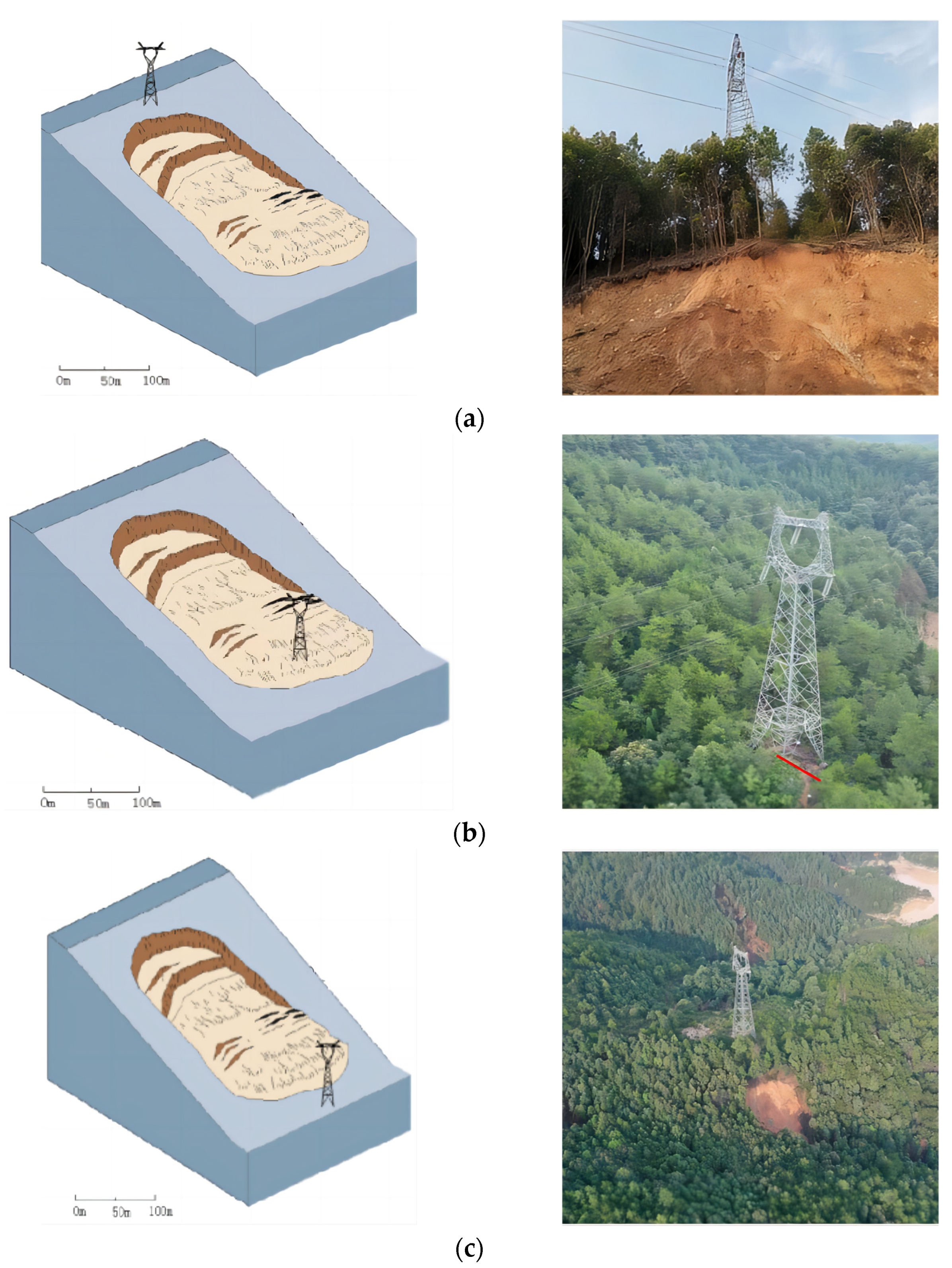
2.2. Relation between the Pole and Tower Position and the Landslide

Through the field investigation, the geological disasters along the overhead transmission line project are more serious. According to incomplete statistics, the number of poles and towers reported to be affected by geological disasters in 2019–2020 in the province is 35, and the number of poles and towers affected by flood disasters is 29. Jingge Line, Jingdiao Line, and Wenzhang Line in the study area have been affected by geological disasters frequently in the past two years, which has caused great hidden dangers to the safety of the power supply in Ji’an city and even in the province. Among them, the relative position relationship between the line tower and landslide disaster can be divided as in Figure 1:
When the pole and tower are located within the influence range of the landslide, the stability of its foundation will be affected no matter what its relative position is, as long as the pole and tower are located within a certain range of the landslide.
In summary, there are two ways to affect the landslide on the tower: one is by acting on the foundation, and the other is directly acting on the tower member. Based on the failure types in this study area, the stability of poles and towers is closely related to different positions, different rainfall intensities, and different slopes. The following analysis and discussion are carried out to study the failure mechanism.

3. Model Introduction

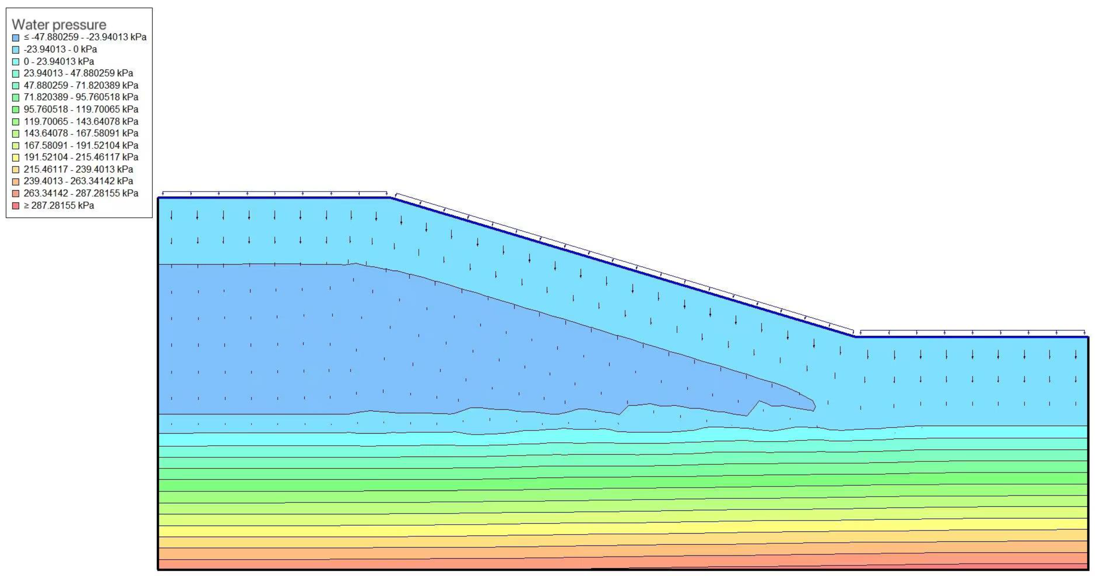
The finite element method can consider slope stability issues from the perspective of stress and strain and has outstanding advantages such as strong applicability and convenience in dealing with heterogeneity, nonlinearity, and complex boundaries. In this paper, the SIGMA/W module and SEEP/W module of Geo-Studio geotechnical engineering simulation software are used for rainfall (the soil–water characteristic curve suitable for engineering analysis can be added by itself, and the movement of the soaked surface and the dissipation process of pore water pressure can be calculated). Based on the simplified typical geological section, combined with the physical and mechanical properties of rock and soil, the load conditions of the tower are designed. Finally, through a variety of integrated analysis and comprehensive evaluation methods, the slope stability analysis and stress–deformation analysis of the slope and pile foundation are carried out.
Among them, there is the slope numerical model SEEP/W module: (1) It is used to analyze the seepage and pore water pressure of porous materials such as soil. (2) It is used for the seepage problem of unsaturated soil. The saturated–unsaturated calculation model in SEEP/W software allows the software to simulate steady-state and transient seepage processes. (3) The saturated–unsaturated calculation model in the software allows the software to simulate steady-state and transient seepage processes. It can add the soil–water characteristic curve suitable for engineering analysis by itself and calculate the movement of the soaked surface and the dissipation process of pore water pressure. SIGMA/W module: (1) With linear and nonlinear elastic models, elastoplastic models, and elastoviscosity models, it can perform stress–strain analysis on soils in different environments. (2) It can calculate the excess pore water pressure of the soil under a load and analyze the slope stability. The pore water pressure in SEEP/W can be called in SIGMA/W to simulate the generation and dissipation of pore water pressure, which is used for slope consolidation settlement and stress–strain analysis.
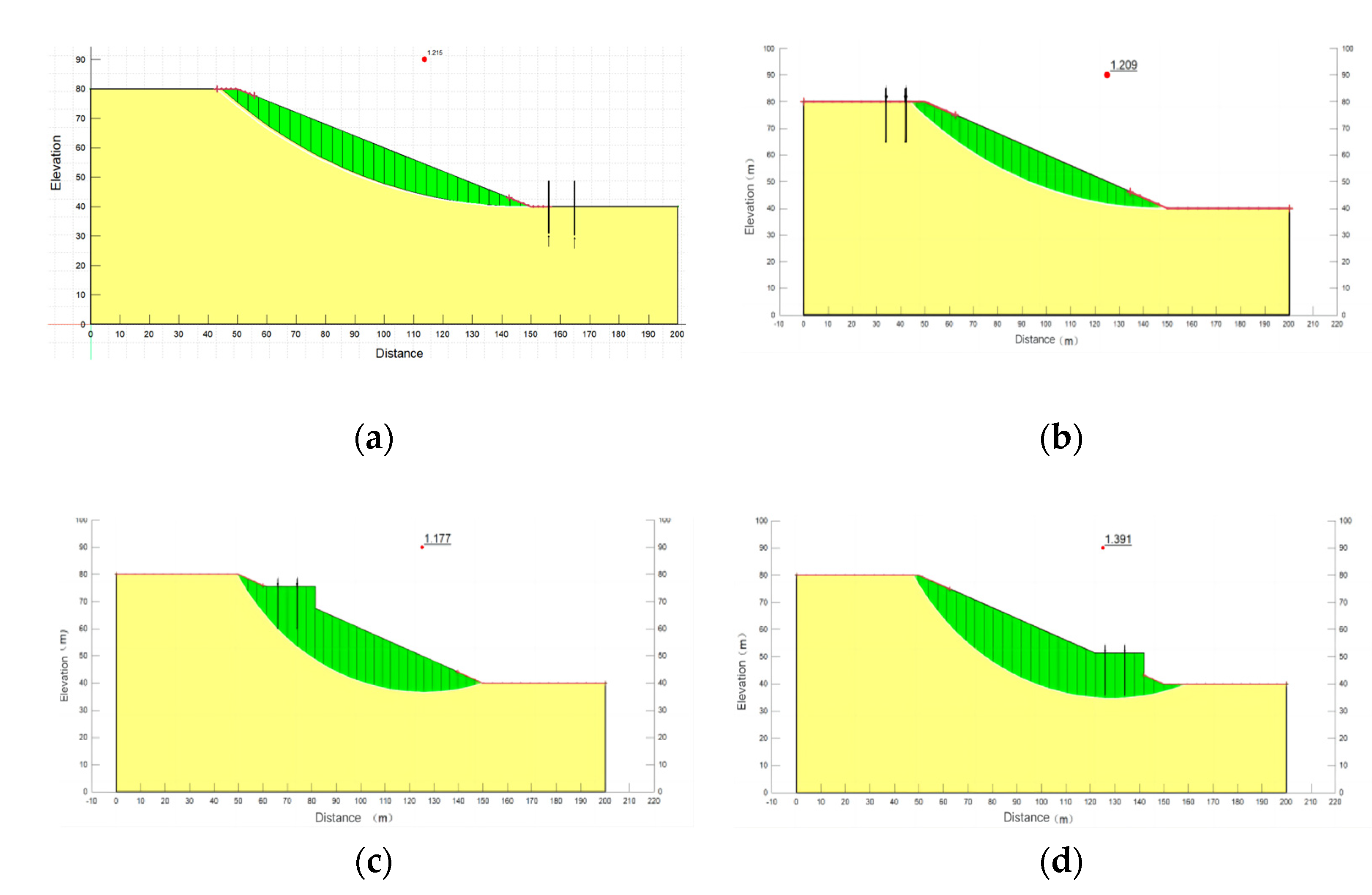
The slope angle of the slope model is 22°, the length is 200 m, and the height is 80 m. The pile length is 15 m and the pile spacing is 8 m. According to the actual situation, x is set as the fixed boundary on the right and left sides of the model, and X-Y is the fixed boundary on the bottom of the model. The parameters of the soil layer and the parameters of the pile foundation are shown in Table 1.

4. Analysis and Discussion of Simulation Results

4.1. Different Pole Positions

4.1.1. Safety Factor Diagram of the Slope at Different Positions of the Pole and Tower

As can be seen in Figure 2 and Figure 3 the safety factor of the pole and tower at the bottom of the slope is higher than that at the top of the slope, which are 1.215 and 1.209, respectively. When the tower is located at the lower slope, the safety factor is 1.391, and the safety factor is the highest. When the tower is located on the slope, the safety factor is the lowest: 1.177.
The safety factor of the slope is the highest when the pole and tower are located on the lower part of the slope, while the safety factor of the slope is the lowest when the pole and tower are located on the upper part of the slope, and the slope may be unstable under some extreme conditions.

4.1.2. Maximum Stress Diagram of the Slope at Different Positions of the Pole and Tower

In general, the slope is mainly affected by gravity, and the maximum total stress on the slope surface increases with the increase in depth. The isoline is basically parallel to the slope surface, and the stress concentration occurs in the downward direction of the extension pile. When the pole and tower are located on the slope, the stress concentration will occur at the bottom of the platform, no matter whether the position is up or down, and the stress concentration range near the bottom of the platform is larger than that near the top of the slope.
In the four cases, the maximum total stress on the slope increases with the increase in depth, the contour line is basically parallel to the slope surface, and the stress concentration occurs in the downward direction of the extension pile. However, no matter where the tower is located on the slope, the soil structure under the platform may be damaged, resulting in instability.

4.2. Different Rainfall Intensity

According to the meteorological and hydrological survey of Ji’an city, the maximum daily rainfall is 190 mm. According to the classification criteria of rainfall Table 2, the changes in the seepage field and stress field of the slope were analyzed when the rainfall intensity was 20 mm/d (moderate rain), 45 mm/d (heavy rain), 90 mm/d (heavy rain), and 190 mm/d (heavy rain), and the stability coefficient of the slope was evaluated when the rainfall intensity lasted for 5 d. The rainfall intensity conditions are shown in Table 3.

4.2.1. Seepage Field Analysis

As can be seen in Figure 4, in the process of rainfall infiltration, the pore water pressure in the soil is the same after 5 d of rainfall with different rainfall intensifications. The surface layer and shallow soil of the slope are affected by rainfall, and the soil is almost unaffected after reaching a certain depth. With the same rainfall duration, the greater the rainfall intensity, the more rainfall there is, the larger the saturated area, the smaller the unsaturated area, the greater the rainwater infiltration depth, the deeper the wetting front development, and the greater the pore water pressure increment of shallow soil. The larger the rainfall intensity, the larger the range of pore water pressure affected by rainfall: 190 mm/d > 90 mm/d > 45 mm/d > 20 mm/d.
As can be seen in Figure 5, the pore water pressure changes at different marks of the slope for different rainfall intensifications on the 5th day, and the greater the rainfall intensity, the greater the impact of the rainfall. Because they are shallower from the slope surface, the pore water pressure changes significantly during rainfall, and the pore water pressure changes gradually from negative to positive. The top of slope A changes the most under different rainfall intensities, followed by the middle of slope B, and the bottom of slope C is easily saturated in the rainfall process.

4.2.2. Stress Field Analysis

As shown in Figure 6, the shear stress distribution gradually increases from the slope surface to the slope. The maximum shear stress of shallow soil appears near the slope foot and increases with the increase in rainfall intensity, and the influence range is larger. The maximum shear stress of the slope foot is 60 kPa when the rainfall intensity is 20 mm/d and 80 kPa when the rainfall intensity is 190 mm/d. The greater the shear stress, the higher the possibility of instability at the foot of the slope. Heavy rainfall is not conducive to the stability of the slope. Reinforcement measures should be considered at the foot of the slope to prevent instability damage.
By comparing the maximum shear stress of different rainfall intensities on the 5th day, it can be seen from Figure 7 that the greater the rainfall intensity, the greater the rise in the the maximum shear stress at the monitoring point inside the slope. Comparing the maximum shear stress at different positions, the shear stress at the foot of slope C is greater than that at the middle B and the top A of the slope. Under different rainfall intensities, the maximum shear stress increment of the slope top A and slope middle B is larger than that of slope foot C.

4.2.3. Stability Analysis

Geo-Studio software was used to calculate the stability coefficient of different rainfall intensifications and the position of the slip plane after 5 d of rainfall to make a comprehensive evaluation of the slope. The changes in the slope stability coefficient of different rainfall intensifications after 5 d of rainfall are shown in Figure 8.
In contrast, It can be seen from Figure 9 and Figure 10 that when the rainfall duration is 5 days, the rainfall intensity is 20 mm/d, 45 mm/d, 90 mm/d, and 190 mm/d, and the influence on the slope stability is as follows: the greater the rainfall intensity, the greater the rainwater infiltration depth, the greater the pore water pressure and volume water content changes, the greater the influence range on the shear stress on the slope surface, and the greater the shear stress increment and displacement increment. The stability coefficient of the slope in the natural state is 1.221, which is in a stable state. Under different rainfall intensities, the stability coefficient is 1.201, 1.138, 1.063, and 0.981, respectively, and the decrease is 1.64%, 6.80%, 12.94%, and 19.66%. The rainfall intensity 190 mm/d, The slope reached an unstable state 5 days after the rainfall. With the same rainfall duration, the rainfall intensity has a negative correlation with the slope stability coefficient, and the greater the rainfall intensity, the greater the possibility of slope instability.

4.3. Different Slope Sizes

In order to study the influence of the soil slope change on its stability under heavy rainfall conditions. As shown in Table 4, four different slope sizes of 15°, 20°, 25°, and 30° were set, respectively, to change the slope of the residual soil, with other parameters unchanged, and the stability coefficient of 190 mm/d rainfall intensity was calculated.
As can be seen in Figure 11, when the slope is 15°, the safety factor of slope stability is 1.058; when the slope is 20°, the safety factor of slope stability is 1.211; when the slope is 25°, the safety factor of slope stability is 1.490; When the slope is 30°, the safety factor of slope stability is 1.788. The greater the internal friction angle, the greater the stability coefficient of the slope. As shown in Figure 12, under different internal friction angles, the stability coefficient decreases gradually with the longer rainfall time and increases gradually after the rain stops. This is because with the infiltration of rainfall, the volume water content of soil gradually increases, the shear strength of soil decreases continuously, and the stability coefficient decreases continuously. In the stage of stopping rain, the rainwater permeates, the volume water content of soil gradually decreases, the shear strength of soil increases, and the stability coefficient shows an increasing trend.

5. Discussion

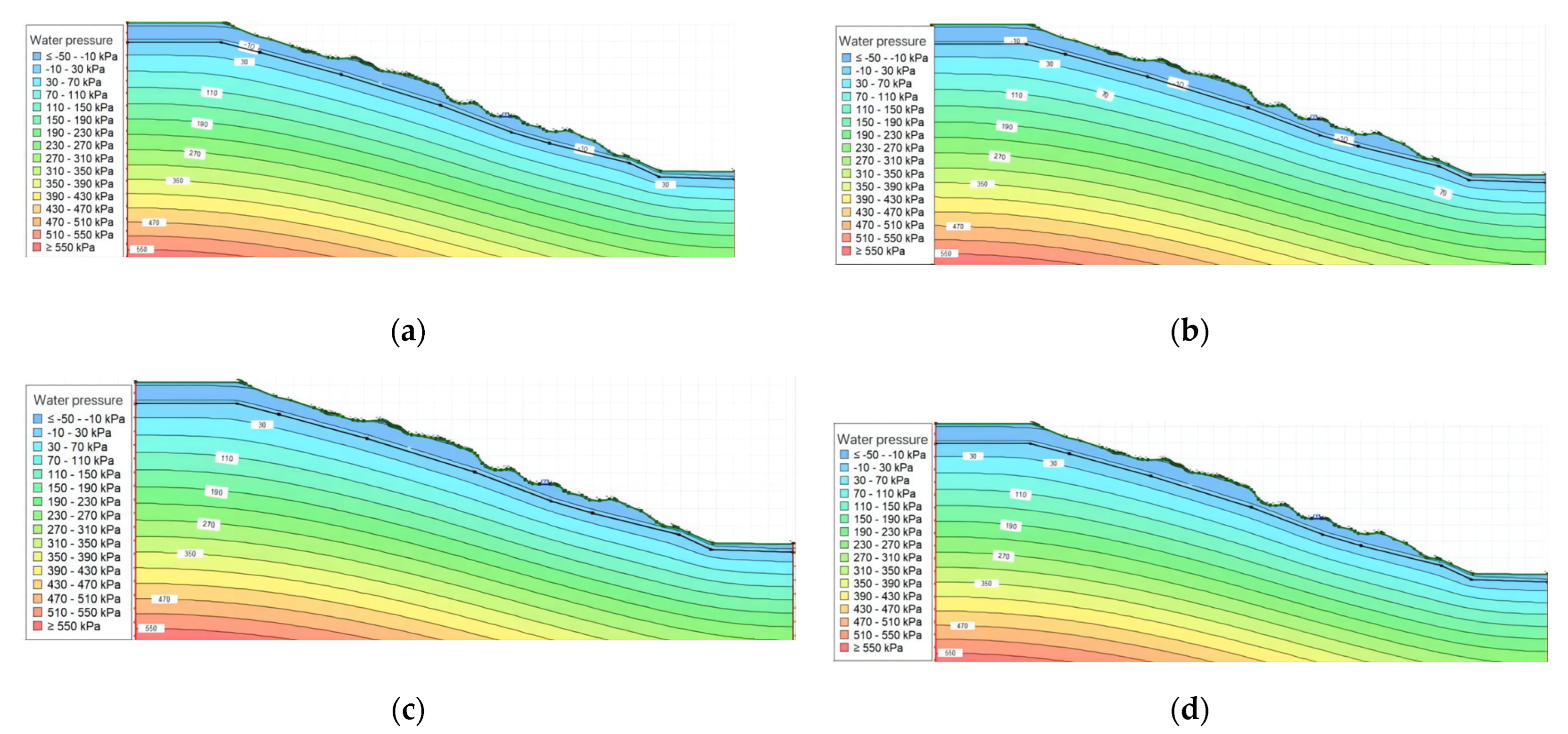
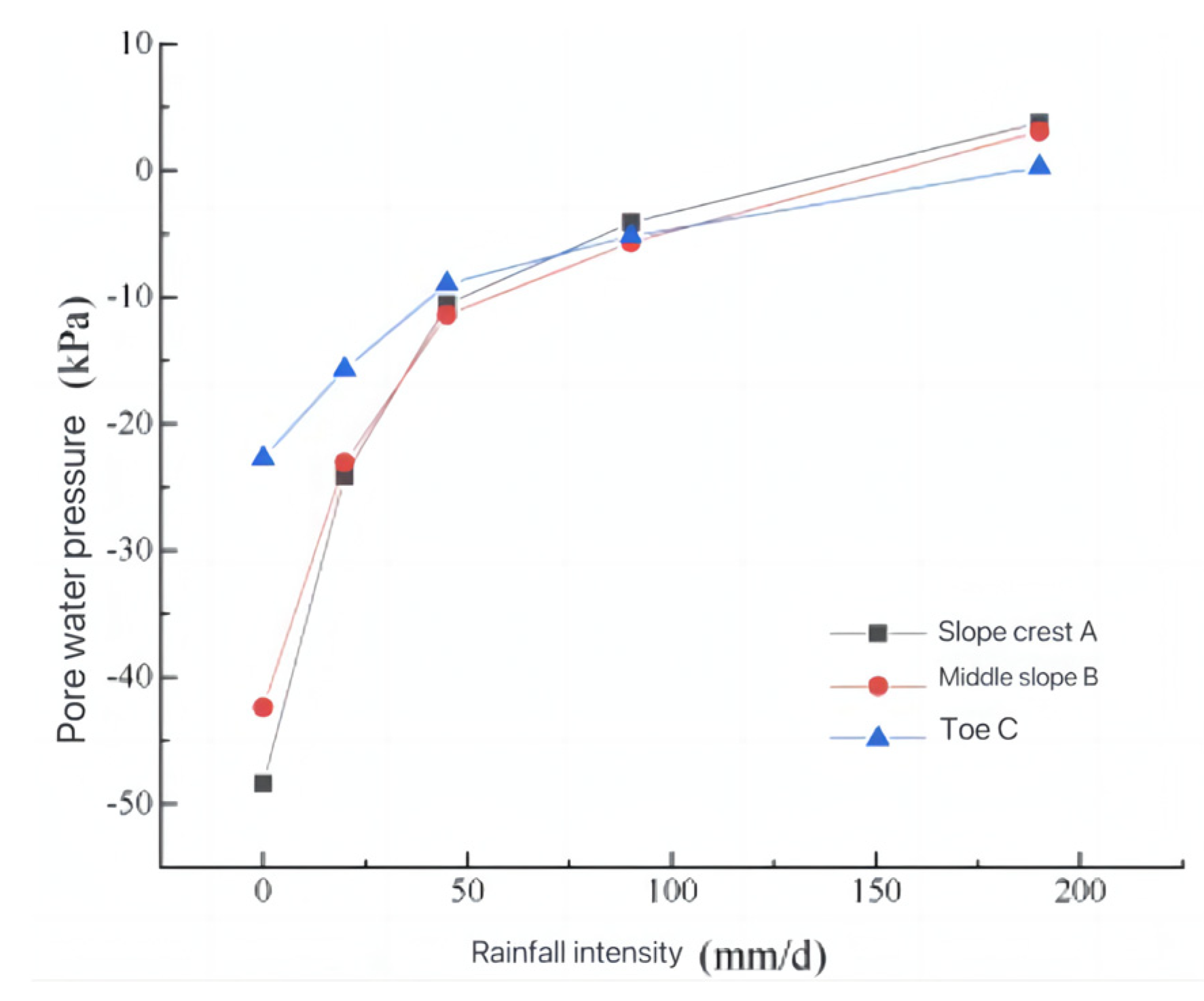
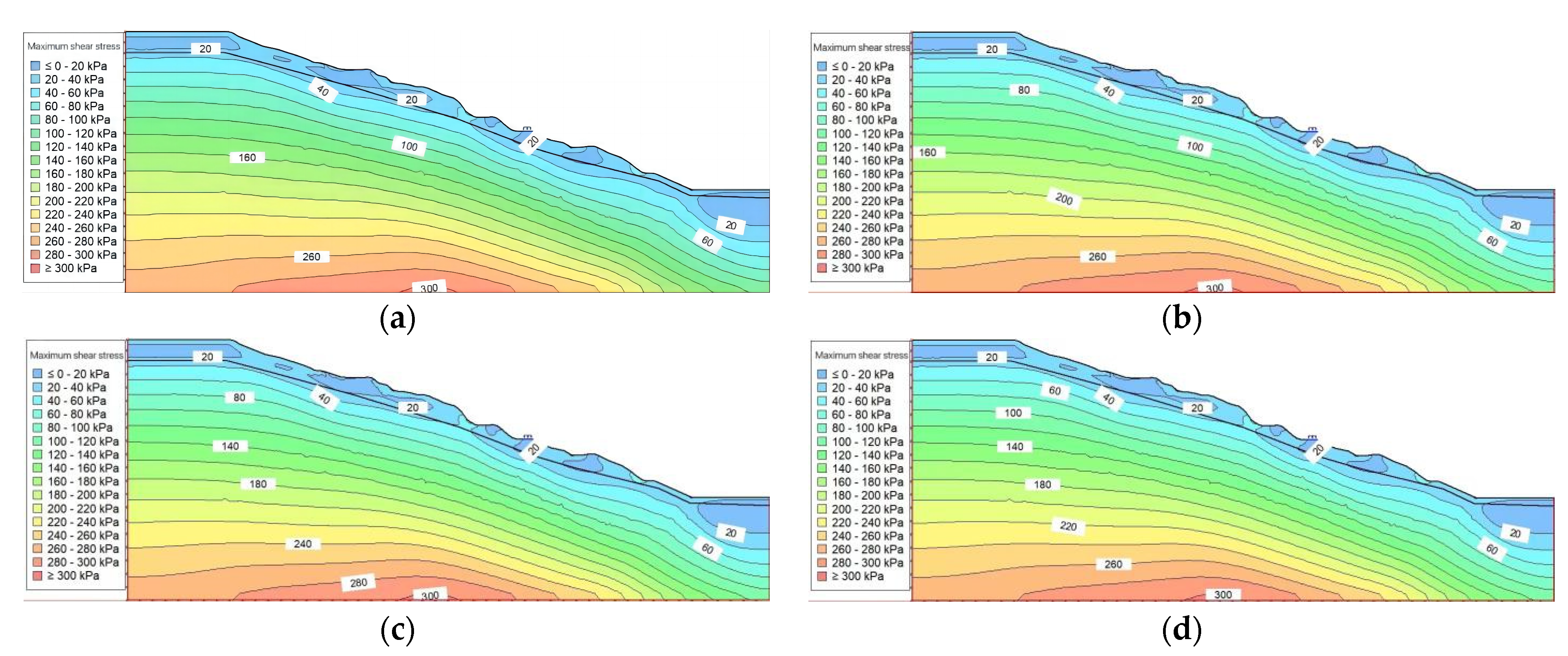
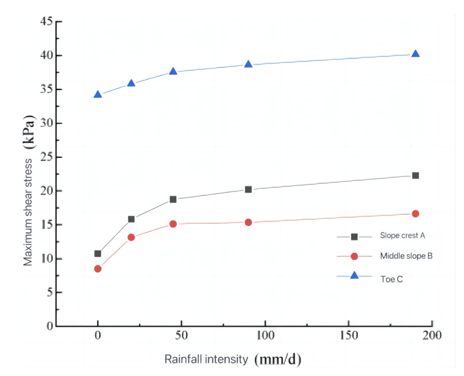
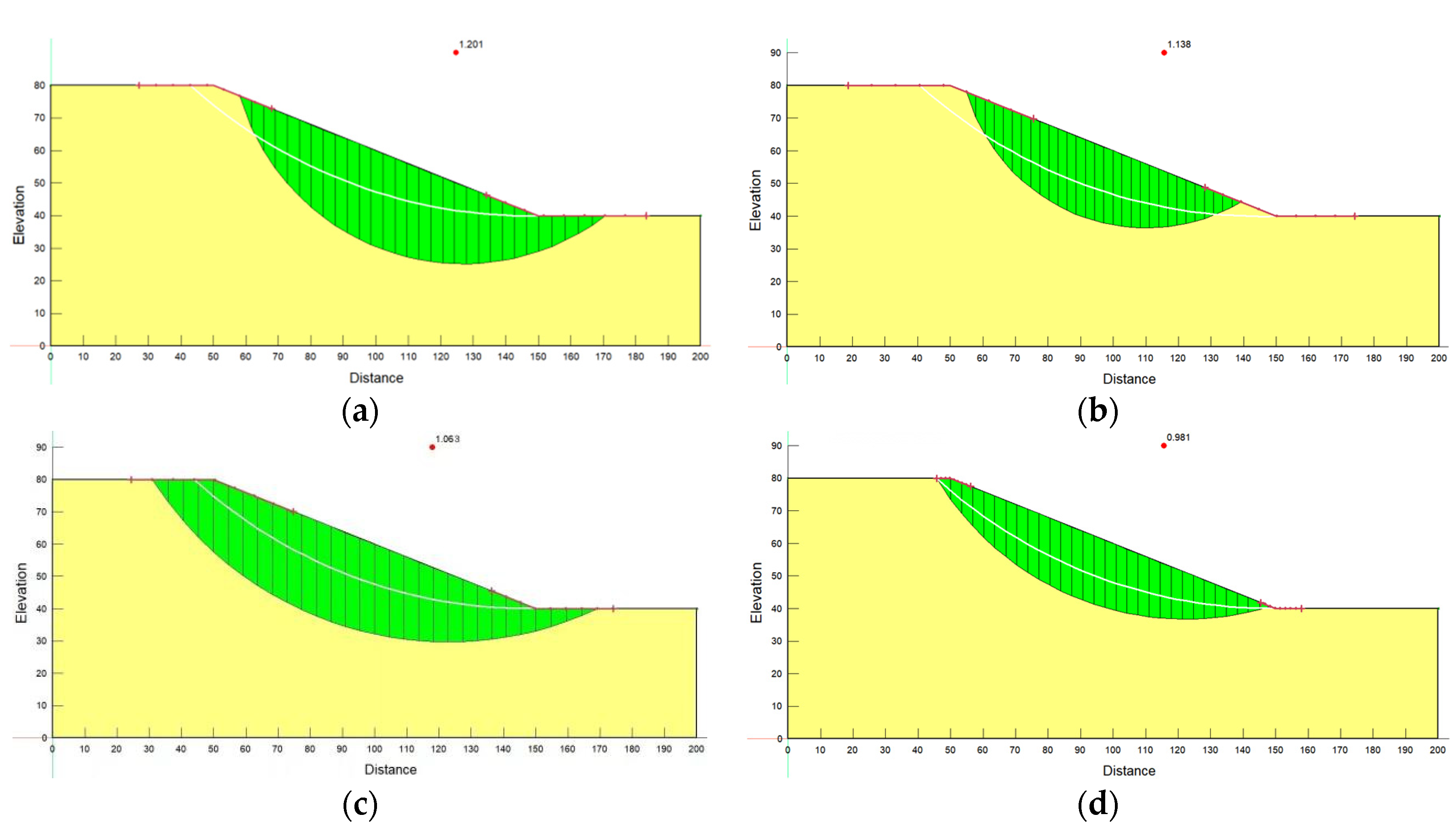
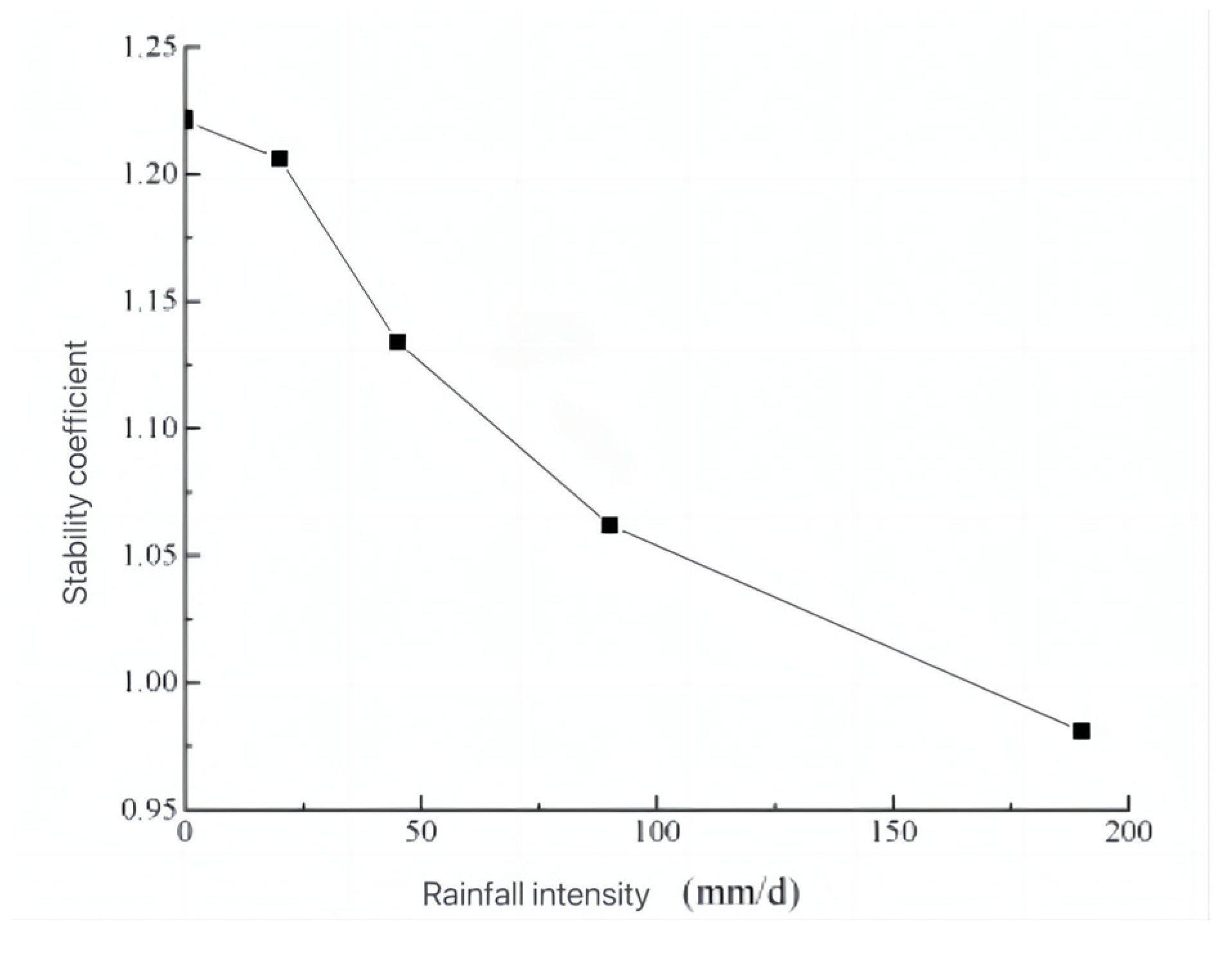
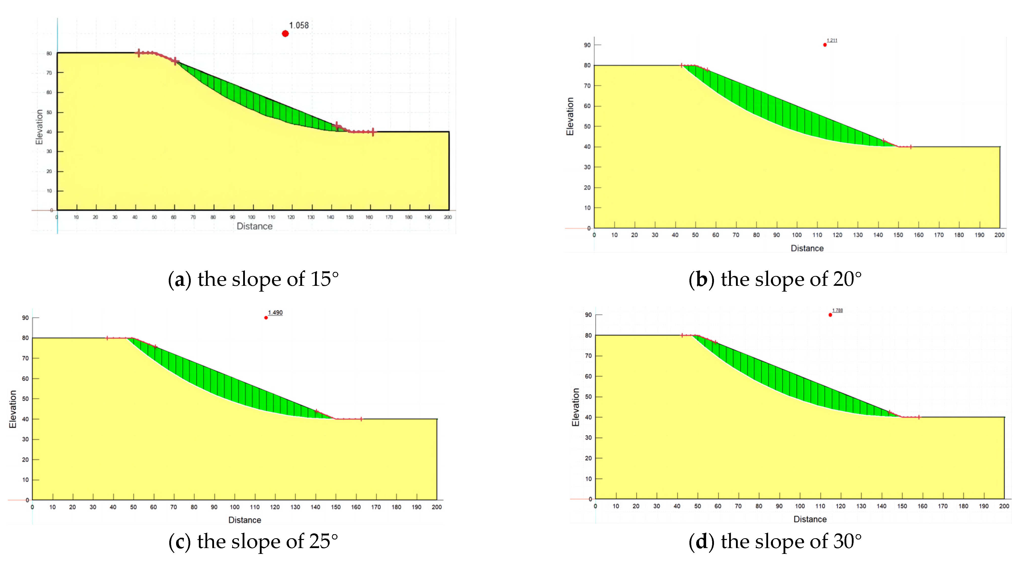
The study intends to focus on the typical unstable slope rock and soil along the transmission line project and intends to use numerical simulation, theoretical analysis and other technical means to carry out the impact of the landslide nature, scale, relative position relationship with the tower, distance, and other influencing factors on the foundation of the tower. The transmission line tower foundation has the characteristics of discontinuity. The significance of this feature is that when the landslide deforms and fails, the safety of the tower will be threatened only when the tower foundation is within the deformation range of the landslide, and the transmission line tower will fail when the landslide occurs. When stable failure occurs, it is impacted by the sliding body and fails. In addition, compared with the rainfall duration of 5 days, the rainfall intensity is: 20 mm/d, 45 mm/d, 90 mm/d, and 190 mm/d. The impact on slope stability: the greater the rainfall intensity, the greater the rainwater infiltration depth, the greater the pore water pressure and volumetric water content change, the greater the range of influence on the shear stress on the slope surface, and the greater the shear stress increment and displacement increment. In the case of the same rainfall intensity and different slope gradients, the smaller the slope gradient, the greater the pore water pressure change, the greater the infiltration depth, and the safety factor of the slope decreases accordingly, and eventually, the slope will fail. These results show that the relative position of the towers, rainfall intensity, and slope will affect the slope stability. Further research can be based on the results of this paper to carry out corresponding experimental analysis and verification work.

6. Conclusions

(1) The finite element analysis method is used to calculate the corresponding safety factors of different pole and tower positions, respectively. The results show that the slope and slope height have an important influence on the selection of a reasonable position of the pole and tower. The safety factor of the slope is the highest when the pole tower is located at the lower part of the slope, which may be because the effect of the pile foundation is equivalent to that of the retaining wall strengthening the slope. Second, the pole and tower are located at the bottom of the slope and the top of the slope, and the safety coefficient of the slope is similar. When the pole and tower are located at the upper part of the slope, the safety coefficient of the slope is the lowest, and there is the possibility of instability under some extreme conditions.
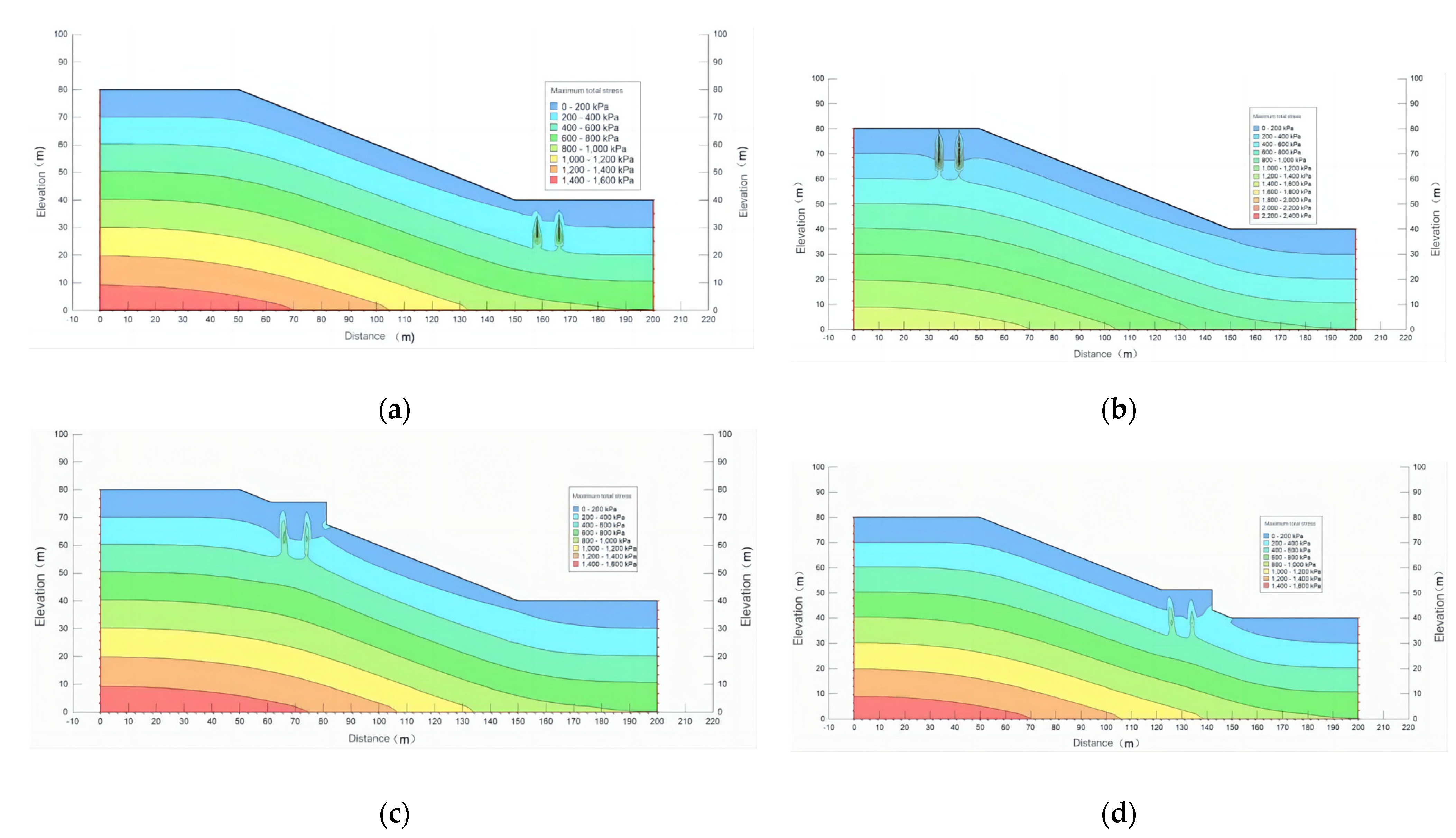
(2) The maximum total stress on the slope increases with the increase in the depth at different positions of the pole and tower, the contour line is basically parallel to the slope surface, and the stress concentration occurs in the downward direction of the extension pile. However, no matter where the tower is located on the slope, the stress concentration will occur at the downhill foot of the platform, and the range will expand from top to bottom, which may cause soil structure damage under the platform, resulting in instability.
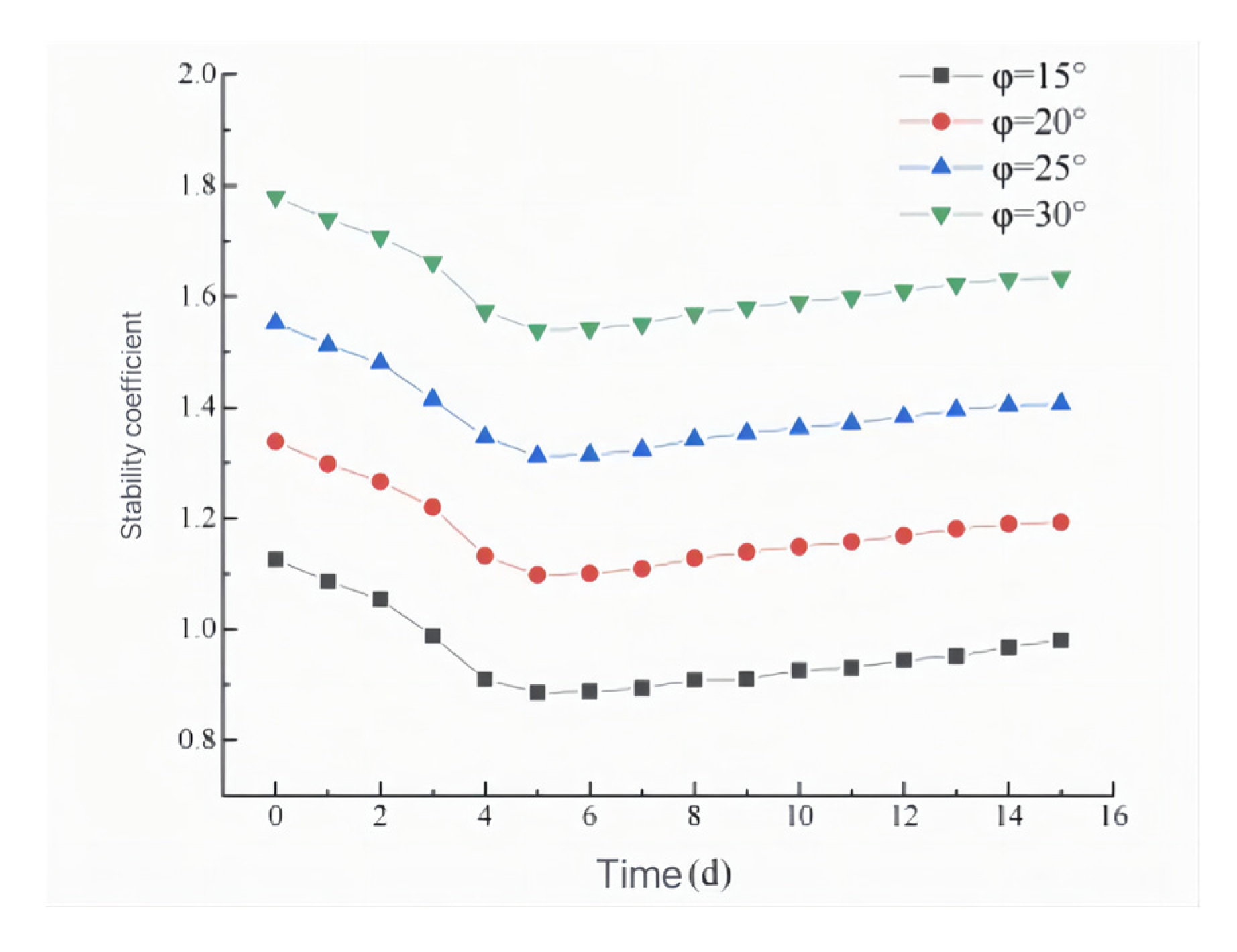
(3) Under normal circumstances, when the rainfall intensity is the same and the slope is different, the smaller the slope is, the easier it is for rainwater to penetrate into the slope, the greater the change in the pore water pressure, the greater the depth of infiltration, the safety factor of the slope will also decrease, and the slope will eventually be destabilized and destroyed. In contrast, when the rainfall duration is 5 days, the rainfall intensity is 20 mm/d, 45 mm/d, 90 mm/d, and 190 mm/d, and the influence on slope stability is as follows: the greater the rainfall intensity, the greater the rainwater infiltration depth, the greater the pore water pressure and volume water content changes, the greater the influence range on the shear stress on the slope surface, and the greater the shear stress increment and displacement increment. The stability coefficient of the slope in the natural state is 1.221, which is in the stable state. The results provide a scientific basis for further understanding of the influence mechanism of the slope angle of a column pole on such landslides under rainfall conditions. Further research can be based on the results of this paper to carry out the corresponding experimental analysis and verification work.

Author Contributions

Z.W. is responsible for the design of the model experiments, data processing, and article writing; C.H. and S.H. are responsible for the model testing, article writing, and proofreading; J.L. and L.M. are responsible for the data processing and equipment debugging; T.Z. is in charge of the data processing. All authors have read and agreed to the published version of the manuscript.

Funding

This research was funded by the Donghua University of Science and Technology Doctoral Research Start-up Fund Project (grant No. DHBK2019240), the Natural Science Foundation of China (grant No. 42002258), the Jiangxi Geological Environment and Underground Space EngineeringResearch Center (grant No. JXDHJJ2022-013).

Data Availability Statement

Not applicable.

Acknowledgments

The authors thank State Grid Jiangxi Electric Power Co., Ltd. and the Ji’an Power-Supply Branch of State Grid Jiangxi Electric Power Co., Ltd. for their financial support.

Conflicts of Interest

The authors declare no conflict of interest.

References

  1. Chen, Z. Stability Analysis of Tower Foundation for Transmission Line. Appl. Mech. Mater. 2014, 580–583, 490–493. [Google Scholar]
  2. Huang, C. Landslide area under extreme conditions Evaluation and Analysis of Tower Foundation Instability of EHV Transmission Line. Saf. Environ. Eng. 2021, 28, 139–147. [Google Scholar]
  3. Zhang, X.D.; Ye, P.; Wu, Y. Enhanced technology for sewage sludge advanced dewatering from an engineering practice perspective: A review. J. Environ. Manag. 2022, 321, 115938. [Google Scholar] [CrossRef] [PubMed]
  4. Zhang, X.D.; Wu, Y.; Zhai, E.; Ye, P. Coupling analysis of the heat-water dynamics and frozen depth in a seasonally frozen zone. J. Hydrol. 2021, 593, 125603. [Google Scholar] [CrossRef]
  5. Li, S.; Li, Y.; Yin, K.; Zhong, Y.; Liu, Y.; Xu, Y. Study on the effect of tower foundation landslide protection measures based on a physical model test. Bull. Geol. Sci. Technol. 2022, 41, 209–218. [Google Scholar]
  6. Yu, W.; Wu, C.; Dai, J.; Zhang, Z.; Hu, X.; Wang, F. Selection and application of slope protection schemes for transmission line towers in mountainous areas. Electr. Power Surv. Des. 2020, 6, 67–72. [Google Scholar]
  7. Urciuoli, G.; Pirone, M.; Comegna, L.; Picarelli, L. Long-term investigations on the pore pressure regime in saturated and unsaturated sloping soils. Eng. Geol. 2016, 212, 98–119. [Google Scholar] [CrossRef]
  8. Muraro, S.; Madaschi, A.; Gajo, A. Passive soil pressure on sloping ground and design of retaining structures for slope stabilisation. Geotechnique 2015, 65, 507–516. [Google Scholar] [CrossRef]
  9. Kaczmarek, L.; Dobak, P.; Szczepanski, T.; Kielbasinski, K. Triaxial creep tests of glacitectonically disturbed stiff clay–structural, strength, and slope stability aspects. Open Geosci. 2021, 13, 1118–1138. [Google Scholar] [CrossRef]
  10. Zhang, X.D.; Shu, C.J.; Wu, Y.J.; Ye, P.; Du, D.W. Advances of coupled water-heat-salt theory and test techniques for soils in cold and arid regions: A review. Geoderma 2023, 432, 116378. [Google Scholar] [CrossRef]
  11. Buma, J. Finding the most suitable slope stability model for theassessment of the impact of climate change on a landslide insoutheast France. Earth Surf. Process. Land Forms 2000, 25, 565–582. [Google Scholar] [CrossRef]
  12. Lan, H.X.; Zhou, C.H.; Lee, C.F.; Wang, S.J.; Wu, F.Q. Rainfall-induced landslide stability analysis in response to transient pore pressure-A casestudy of natural terrain landslide in Hong Kong. Sci. China (Ser. E Technol. Sci.) 2003, 46, 52–68. [Google Scholar] [CrossRef]
  13. Liu, B.; Li, S.; Zhang, L.; Wang, J. Experimental and discrete ele-ment numerical analysis of side slope instability induced by fis-sure water underlying impervious bed. Sci. China (Ser. E Technol. Sci.) 2005, 48, 65–80. [Google Scholar]
  14. Zhang, L.; Wei, Z.; Liu, X.; Li, S. Application of three-dimensional discrete element face-to-face contact model with fissure waterpressure to stability analysis of landslide in Panluo iron mine. Sci. China (Ser. E Technol. Sci.) 2005, 48, 146–156. [Google Scholar]
  15. Liang, X.; Gui, L.; Wang, W.; Du, J.; Ma, F.; Yin, K. Characterizing the developmentpattern of a Colluvial Landslide based on long-term monitoringin the Three Gorges Reservoir. Remote Sens. 2021, 13, 224. [Google Scholar] [CrossRef]
  16. Xu, J.; Shang, Y.; Chen, K.; Yang, J. Stability analysis of shallow landslides under heavy rainfall. J. Rock Mech. Eng. 2005, 24, 3246–3251. [Google Scholar]
  17. Chang, J.; Bao, H.; Wu, F.; Luo, H. Discussion on the Stability of Shallow Landslides under Rainfall Conditions. Rock Soil Mech. 2015, 36, 995–1001. [Google Scholar]
  18. Liang, X.; Yin, K.; Chen, L.; Kang, X.; Yang, Y.; Zhang, L. Water Level Fluctuation Over Reservoir and Effect of Rainfall Fluid-solid coupling characteristics and stability analysis of Ganjingzi landslide in Xiawu Gorge. Chin. J. Geol. Hazards Prev. 2019, 30, 3040. [Google Scholar]
  19. Yang, X.; Wang, Y.; Zhang, B. Ancient landslides caused by highway construction Case analysis of resurrection. Geol. Hazards Environ. Prot. 2002, 3, 43–46. [Google Scholar]
  20. Peng, N.; Yan, E.; Zhu, X. Analysis of Deformation and Failure of Landslide due to Excavation and Rainfall. Build. Technol. 2016, 38, 120–122. [Google Scholar]
  21. Tian, D.; Zheng, H.; Liu, D. Model test research on deformation characteristics of ancient landslides under the conditions of reservoir water fluctuation and rainfall. Rock Soil Mech. 2021, 42, 471–480. [Google Scholar]
  22. Wang, R.; Xia, R.; Xu, W. Experimental Research on Physical Simulation of Landslide Accumulation Rainfall Infiltration Process. Eng. Sci. Technol. 2019, 51, 47–54. [Google Scholar]
  23. Yang, D.; Hu, X.; Xu, C. Deformation evolution characteristics of multi-layer slip zone landslide based on physical model test. Geol. Sci. Technol. Bull. 2022, 41, 300–308. [Google Scholar]
  24. Chen, Y.; Ma, D.; Yang, M. Ultra-high voltage transmission line tower Characteristic analysis and treatment of base landslide hazards. Electr. Power Constr. 2014, 35, 69–73. [Google Scholar]
  25. Guo, L.; Guo, Y.; Wang, J. Analysis of geological hazards of towers in Tibet section of Chuanhui transmission line. Yunnan Hydraul. Power Power Gener. 2019, 35, 17–19. [Google Scholar]
  26. Zhang, H.; He, W.; Xie, H. Research on landslide problems in high-voltage overhead transmission line engineering. Shanxi Archit. 2014, 40, 57–58. [Google Scholar]
  27. Feng, D. Landslide Treatment and Analysis of Overhead Transmission Line Tower Foundation. East China Sci. Technol. (Acad. Ed.) 2017, 231, 238. [Google Scholar]
  28. Zhang, X.; Shu, C.; Fujii, M.; Wu, Y.; Sun, D.; Ye, P.; Bao, Y. Numerical and Experimental Study on Water-Heat-Salt Transport Patterns in Shallow Bare Soil with Varying Salt Contents under Evaporative Conditions: A Comparative Investigation. J. Hydrol. 2023, 621, 129564. [Google Scholar] [CrossRef]
  29. Zhang, X.; Du, D.; Wu, Y.; Ye, P.; Xu, Y. Theoretical and analytical solution on vacuum preloading consolidation of landfill sludge treated by freeze–thaw and chemical preconditioning. Acta Geotech. 2023, 1–18. [Google Scholar] [CrossRef]
  30. Potts, D.M.; Zdravković, L.; Addenbrooke, T.I.; Higgins, K.G.; Kovačević, N. Finite Element Analysis In Geotechnical Engineering; Thomas Telford: London, UK, 2001. [Google Scholar]
Figure 1. Contour map of the water pressure and groundwater level.
Water 15 03654 g001
Figure 2. Relative position relationship between the tower and landslide disaster. (a) The tower is located at the top of the slide. (b) The pole and tower are located within the range of the sliding body. (c) The tower is located below the slope.
Water 15 03654 g002
Figure 3. Safety factor diagram of slope at different positions of poles and towers. (a) The tower is at the bottom of the slope. (b) The tower is located at the top of the slope. (c) The tower is located in the upper part of the broken surface. (d) The pole and tower are located on the lower part of the slope.
Water 15 03654 g003
Figure 4. Maximum stress diagram of the slope at different positions of poles and towers. (a) The tower is at the bottom of the slope. (b) The tower is located at the top of the slope. (c) The tower is located in the upper part of the broken surface. (d) The pole and tower are located on the lower part of the slope.
Water 15 03654 g004
Figure 5. Distribution of the pore water pressure contour under different rainfall intensities. (a) 20 mm/d. (b) 45 mm/d. (c) 90 mm/d. (d) 190 mm/d.
Water 15 03654 g005
Figure 6. The change diagram of the pore water pressure on the 5th d of rainfall under different rainfall intensities.
Water 15 03654 g006
Figure 7. Maximum shear stress contour distribution on the 5th day of rainfall under different rainfall intensities. (a) 20 mm/d. (b) 45 mm/d. (c) 90 mm/d. (d) 190 mm/d.
Water 15 03654 g007
Figure 8. Change diagram of the maximum shear stress in monitoring the node for 5 d under different rainfall intensities.
Water 15 03654 g008
Figure 9. Stability coefficient and slip plane position on the fifth day of rainfall under different rainfall intensities. (a) 20 mm/d. (b) 45 mm/d. (c) 90 mm/d. (d) 190 mm/d.
Water 15 03654 g009
Figure 10. Variation chart of the safety factor on the 5th day of rainfall under different rainfall intensities.
Water 15 03654 g010
Figure 11. The stability coefficient and slip plane position of different slope angles.
Water 15 03654 g011
Figure 12. The influence of different slope angles on the slope stability under heavy rain.
Water 15 03654 g012
Table 1. Parameter values of the soil layer.
Cohesive Force
C   ( K P a )
Angle of Internal Friction
(°)
Natural Weight
( k N / m 3 )
Poisson’s RatioModulus of Elasticity
( K P a )
Soil layer12.3820200.35100,000
Table 2. Design scheme table of different rainfall intensity conditions.
Scheme NumberRainfall LevelRainfall Intensity
(mm/d)
Duration of Rainfall
(d)
A-1Moderate rain205
A-2Heavy rain455
A-3Rainstorm905
A-4Downpour1905
Table 3. Different rainfall intensity conditions.
Rainfall ClassSpitModerate RainHeavy RainRainstormDownpourExtremely Heavy Rainstorm
Daily rainfall (mm)<1010–2525–5050–100100–250>250
Table 4. Design scheme table of different slope angle conditions.
Slope15°20°25°30°
Stability coefficient1.0581.2111.4901.788
Disclaimer/Publisher’s Note: The statements, opinions and data contained in all publications are solely those of the individual author(s) and contributor(s) and not of MDPI and/or the editor(s). MDPI and/or the editor(s) disclaim responsibility for any injury to people or property resulting from any ideas, methods, instructions or products referred to in the content.

