
Basin-Scale Hydraulic Evaluation of Groundwater Flow Controlled Biogenic Gas Migration and Accumulation in the Central Pannonian Basin

Abstract
:1. Introduction
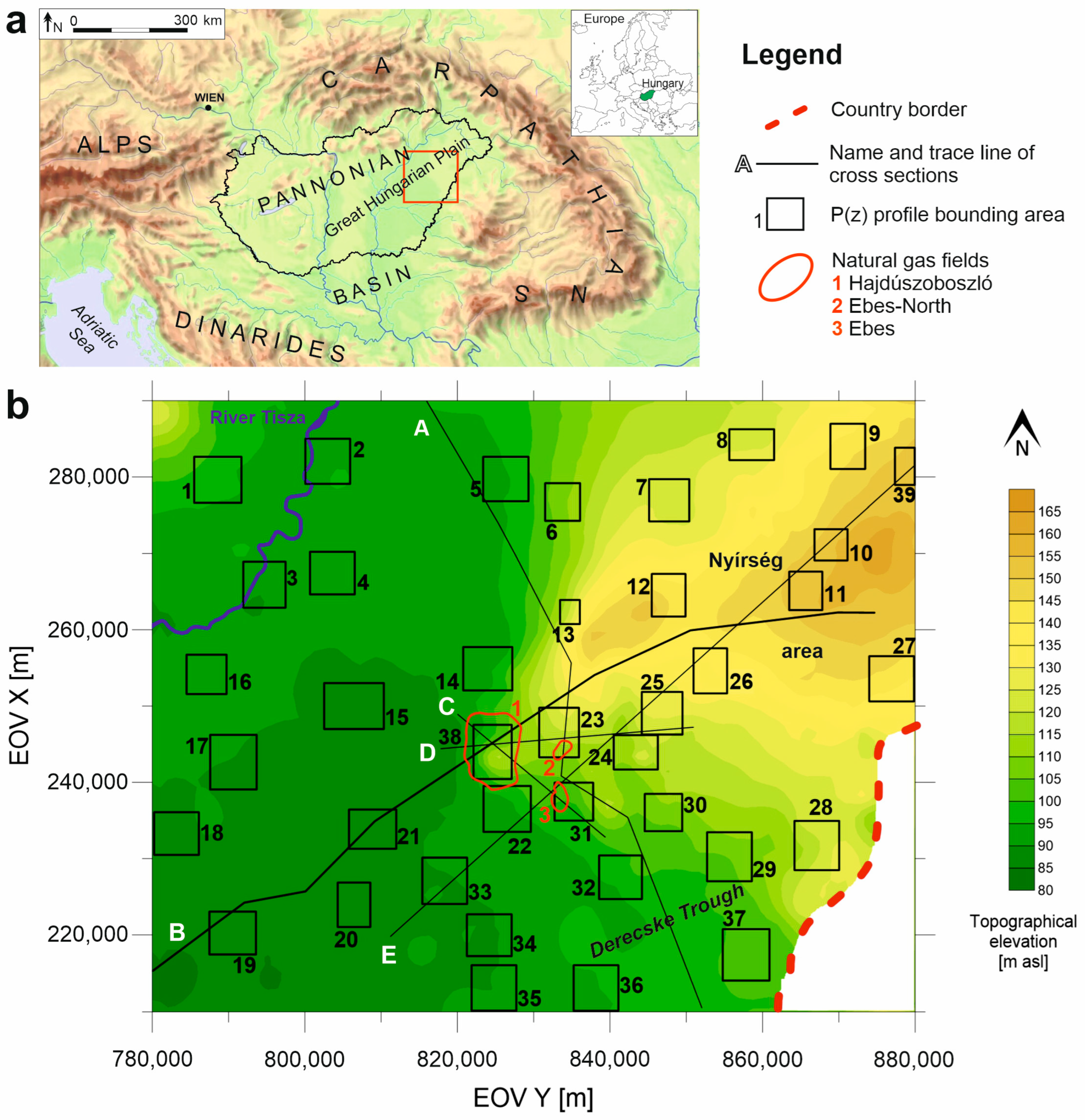
2. Study Area
2.1. Geological and Hydrostratigraphic Background
2.2. Groundwater Flow Systems
2.3. Biogenic Gas Fields
3. Materials and Basin-Scale Hydraulic Evaluation Methodology
3.1. Hydrostratigraphic Interpretation
3.2. Hydraulic Data Preparation
3.3. Elevation Profiles
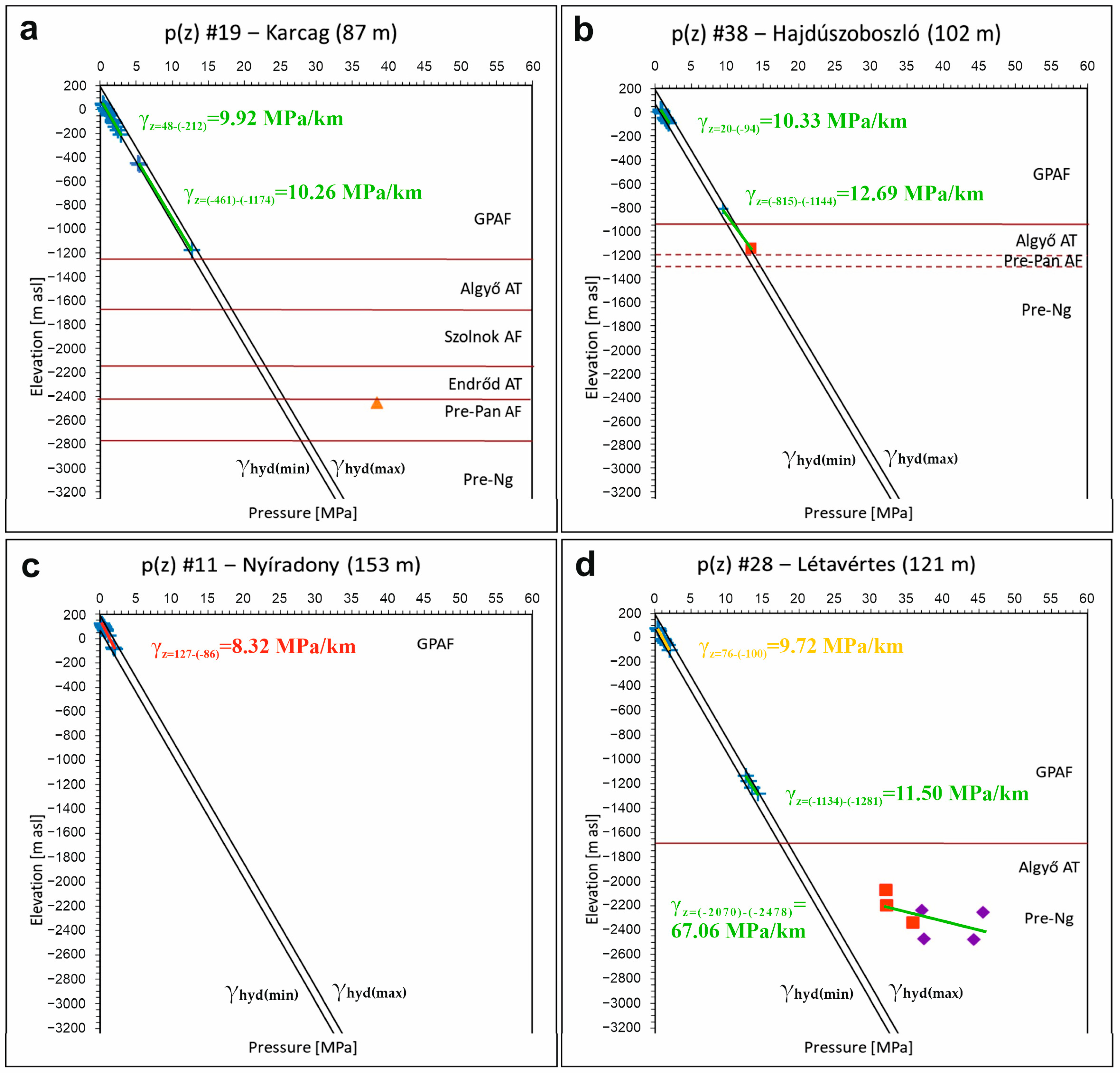
3.3.1. Bulk p(z) Profile
3.3.2. Local p(z) Profiles
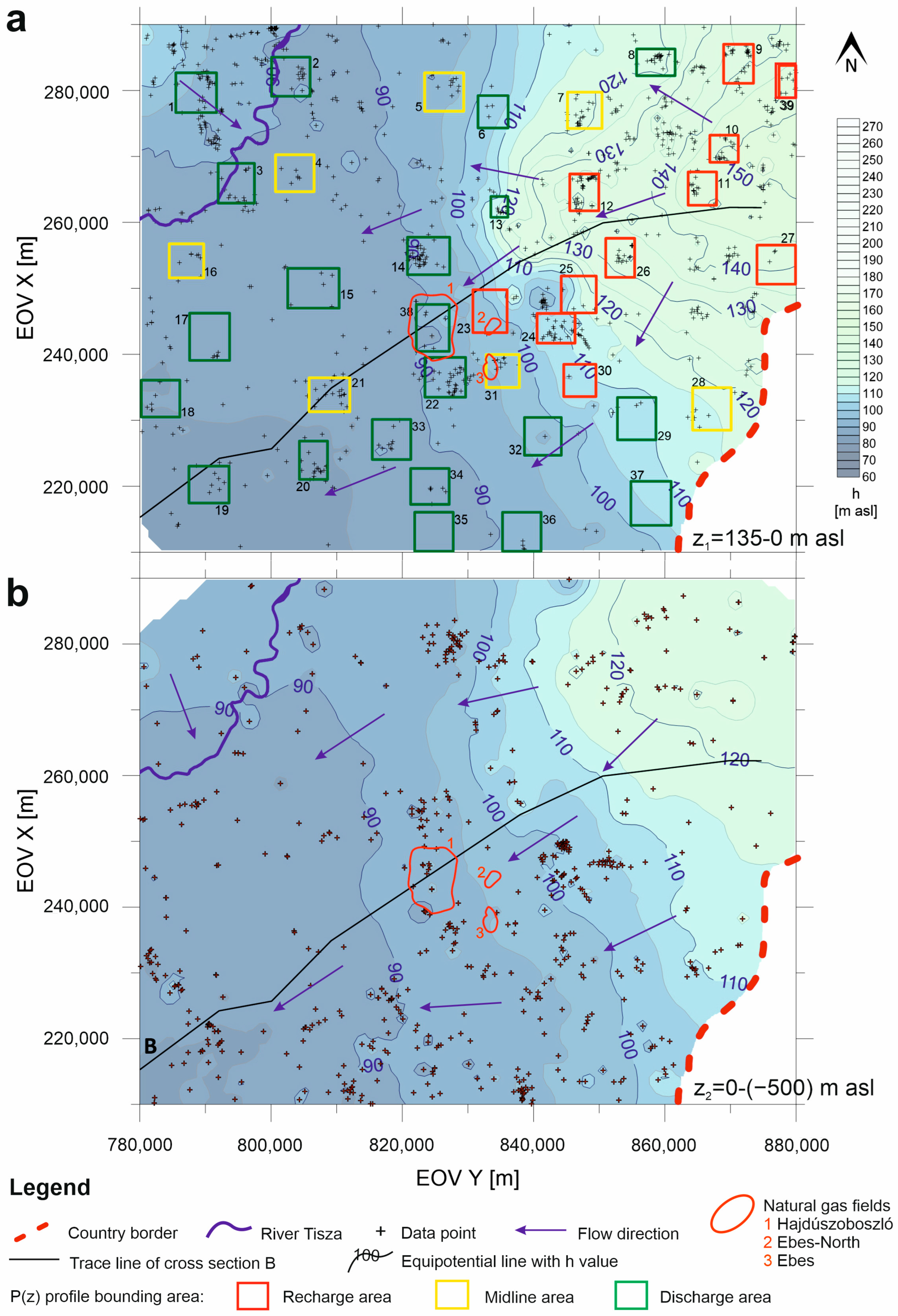
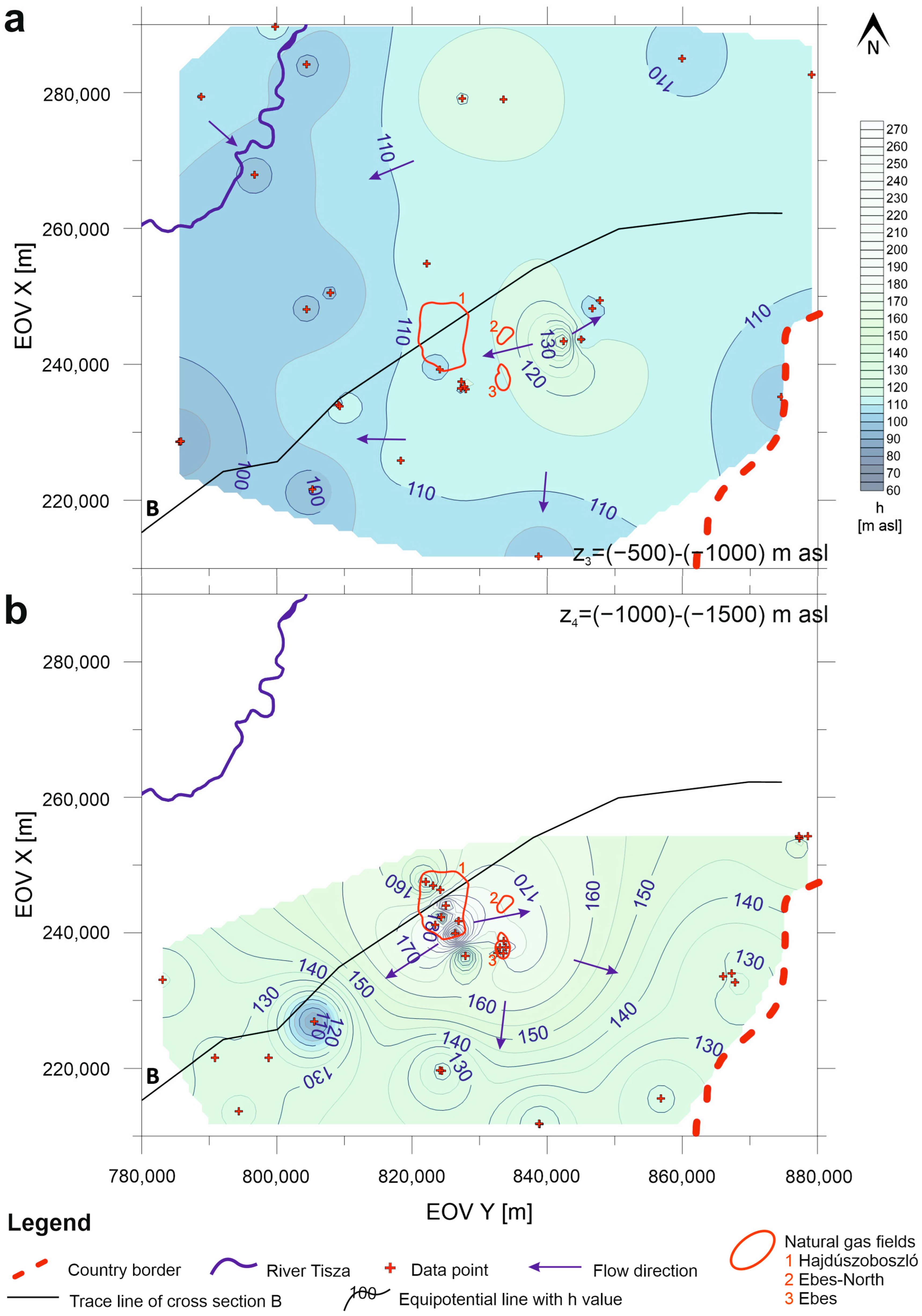
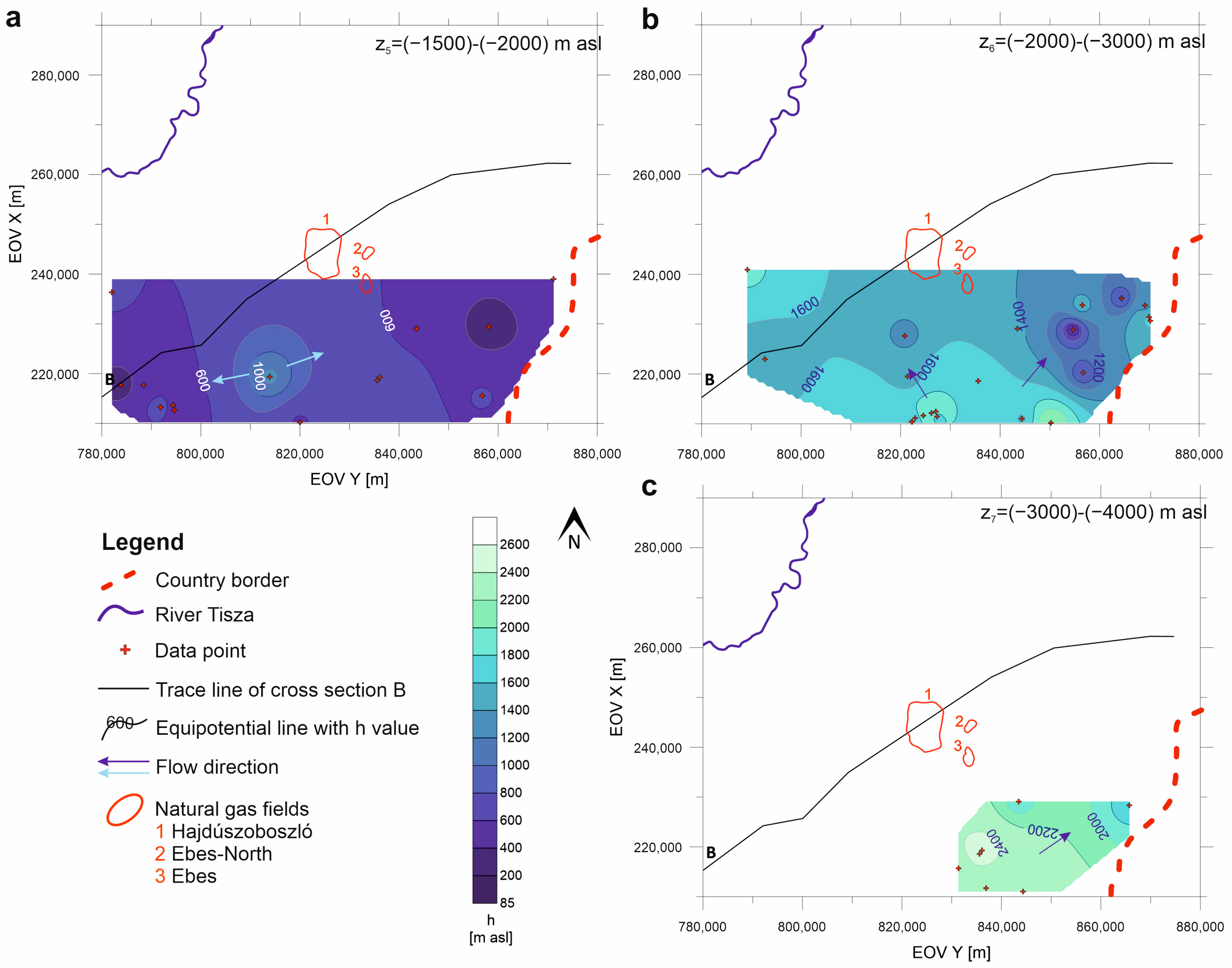
3.4. Tomographic Fluid Potential Maps and Hydraulic Cross Sections
4. Results and Interpretations
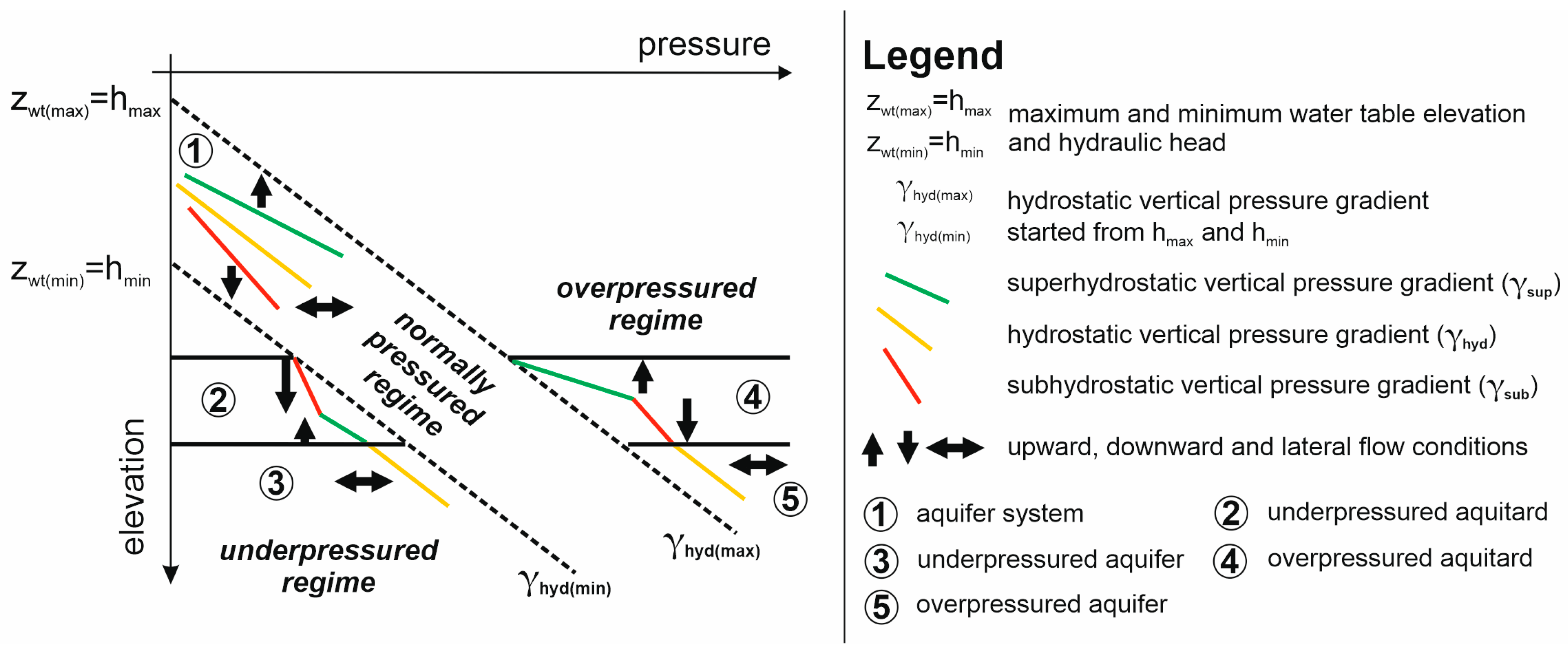
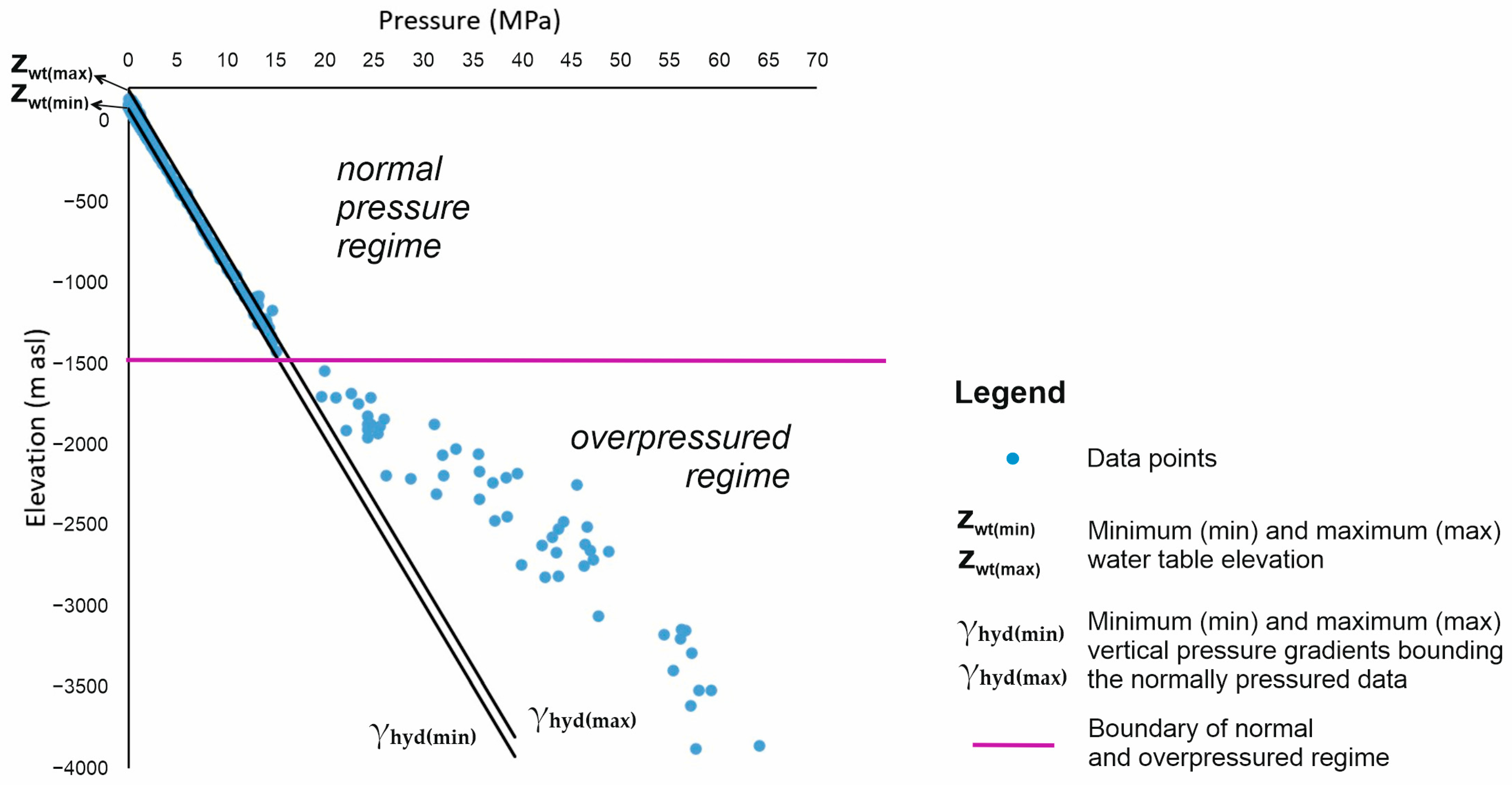
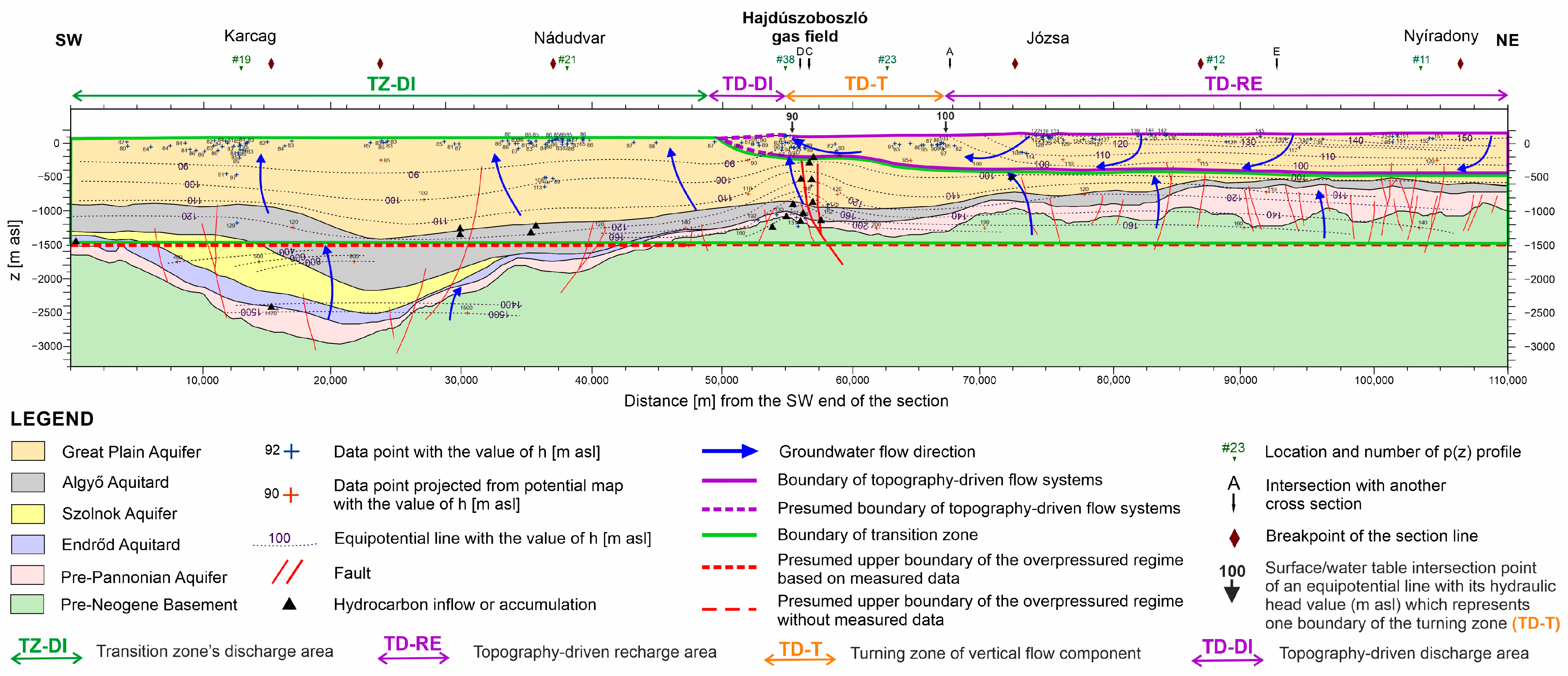
4.1. Regional Pressure Regimes and Vertical Flow Components
4.2. Regional Horizontal Groundwater Flow Conditions
4.3. Regional Groundwater Flow Pattern
4.3.1. NE Part of the Study Area
4.3.2. SW Part of the Study Area
4.3.3. Biogenic Gas Fields
5. Discussion
5.1. Developed Methodology of Basin-Scale Hydraulic Evaluation
5.2. Regional Groundwater Flow System Model of the Great Hungarian Plain, Central Pannonian Basin
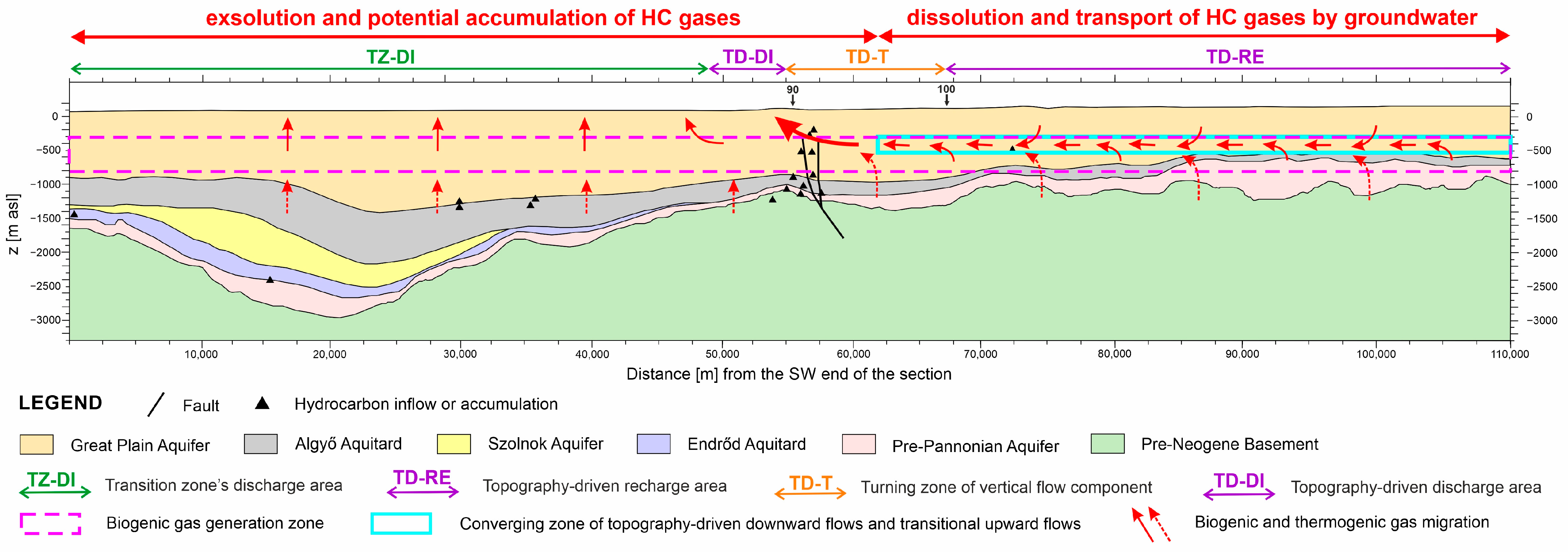
5.3. Groundwater Flow Controlled Migration and Accumulation Model of Dissolved Biogenic Gases
6. Conclusions
Author Contributions
Funding
Data Availability Statement
Acknowledgments
Conflicts of Interest
References
- Katz, B.J. Microbial Processes and Natural Gas Accumulations. Open Geol. J. 2011, 5, 75–83. [Google Scholar] [CrossRef]
- Liu, Y.; Whitman, W.B. Metabolic, phylogenetic, and ecological diversity of the methanogenic Archaea. Ann. N. Y. Acad. Sci. 2008, 1125, 171–189. [Google Scholar] [CrossRef]
- Schneider, F.; Dubille, M.; Montadert, L. Modeling of microbial gas generation: Application to the eastern Mediterranean “Biogenic Play”. Geol. Acta 2016, 14, 403–417. [Google Scholar] [CrossRef]
- Clayton, C. Source volumetrics of biogenic gas generation. In Bacterial Gas; Vially, R., Ed.; Editions Technip: Paris, France, 1992; pp. 191–204. [Google Scholar]
- Belyaev, S.S.; Wolkin, R.; Kenealy, W.R.; Deniro, M.J.; Epstein, S.; Zeikus, J.G. Methanogenic Bacteria from the Bondyuzhskoe Oil Field: General Characterization and Analysis of Stable-Carbon Isotopic Fractionation. Appl. Environ. Microbiol. 1983, 45, 691–697. [Google Scholar] [CrossRef] [PubMed]
- Rice, D. Controls, habitat and resource potential of ancient bacterial gas. In Bacterial Gas; Vially, R., Ed.; Editions Technip: Paris, France, 1992; pp. 91–118. [Google Scholar]
- Brown, A.A. Migration controls on the occurrence of economic bacterial gas accumulations. In Applications of Emerging Technologies: Unconventional Methods in Exploration for Petroleum and Natural Gas V; Institute for the Study of Earth and Man, Southern Methodist University: Dallas, TX, USA, 1997; pp. 84–106. [Google Scholar]
- Perez-Drago, G.; Dubille, M.; Montadert, L.; Brivio, L.; Hosni, M.; Di Biase, D.; Zaky, A. Biogenic and Thermogenic Hydrocarbon Potential of the South Levant Basin and Eastern Nile Delta, Offshore Egypt. In Proceedings of the 81st EAGE Conference and Exhibition 2019, London, UK, 3–6 June 2019; pp. 1–5. [Google Scholar] [CrossRef]
- Pérez-Drago, G.; Mouchot, N.; Dubille, M.; Montadert, L.; Di Biase, D.; Lacone, P.; Mazzarelli, M.; Hosni, M.; Thebault, A. The Importance of Multi-Scale Petroleum System Assessment for Plays and Prospects De-Risking in the Eastern Mediterranean Basin; Search and Discovery Article #11332; American Association of Petroleum Geologists: Tulsa, OK, USA, 2020; p. 19. [Google Scholar] [CrossRef]
- Bartha, A.; Balázs, A.; Szalay, Á. On the tectono-stratigraphic evolution and hydrocarbon systems of extensional back-arc basins: Inferences from 2D basin modelling from the Pannonian basin. Acta Geod. Geophys. 2018, 53, 369–394. [Google Scholar] [CrossRef]
- Schout, G.; Hartog, N.; Hassanizadeh, S.M.; Helmig, R.; Griffioen, J. Impact of groundwater flow on methane gas migration and retention in unconsolidated aquifers. J. Contam. Hydrol. 2020, 230, 103619. [Google Scholar] [CrossRef] [PubMed]
- Hubbert, M.K. Entrapment of Petroleum Under Hydrodynamic Conditions. Am. Assoc. Pet. Geol. Bull. 1956, 37, 1954–2026. [Google Scholar] [CrossRef]
- Tóth, J. Ground water and hydrocarbon migration. In The Geology of North America Vol. O-2, Hydrogeology; Geological Society of America: Boulder, CO, USA, 1988; pp. 485–502. [Google Scholar] [CrossRef]
- Anna, L.O. Effects of Groundwater Flow on the Distribution of Biogenic Gas in Parts of the Northern Great Plains of Canada and United States; Scientific Investigations Report 2010-5251; U.S. Geological Survey: Reston, VA, USA, 2011; 31p. [Google Scholar] [CrossRef]
- Cramer, B.; Poelchau, H.S.; Gerling, P.; Lopatin, N.V.; Littke, R. Methane released from groundwater: The source of natural gas accumulations in northern West Siberia. Mar. Pet. Geol. 1999, 16, 225–244. [Google Scholar] [CrossRef]
- Dang, Y.; Zhao, W.; Su, A.; Zhang, S.; Li, M.; Guan, Z.; Ma, D.; Chen, X.; Shuai, Y.; Wang, H.; et al. Biogenic gas systems in eastern Qaidam Basin. Mar. Pet. Geol. 2008, 25, 344–356. [Google Scholar] [CrossRef]
- Tóth, J. Cross-Formational Gravity-Flow of Groundwater: A Mechanism of the Transport and Accumulation of Petroleum (The Generalized Hydraulic Theory of Petroleum Migration). In Problems of Petroleum Migration, Studies in Geology No 10; Roberts, W.H.I., Cordell, R.J., Eds.; American Association of Petroleum Geologists: Tulsa, OK, USA, 1980; pp. 121–167. [Google Scholar]
- Jiang, X.-W.; Wang, X.-S.; Wan, L.; Ge, S. An analytical study on stagnation points in nested flow systems in basins with depth-decaying hydraulic conductivity. Water Resour. Res. 2011, 47, 1–16. [Google Scholar] [CrossRef]
- Jiang, X.-W.; Wan, L.; Ge, S.; Cao, G.-L.; Hou, G.-C.; Hu, F.-S.; Wang, X.-S.; Li, H.; Liang, S.-H. A quantitative study on accumulation of age mass around stagnation points in nested flow systems. Water Resour. Res. 2012, 48, 1–14. [Google Scholar] [CrossRef]
- Wells, P.R.A. Hydrodynamic Trapping in the Cretaceous Nahr Umr Lower Sand of the North Area, Offshore Qatar. J. Pet. Technol. 1988, 40, 357–361. [Google Scholar] [CrossRef]
- Czauner, B.; Mádl-Szőnyi, J. Regional hydraulic behavior of structural zones and sedimentological heterogeneities in an overpressured sedimentary basin. Mar. Pet. Geol. 2013, 48, 260–274. [Google Scholar] [CrossRef]
- Czauner, B.; Szkolnikovics-Simon, S.; Mádl-Szőnyi, J. The influence of deep groundwater flow systems on the Earth’s critical zone. In Proceedings of the EGU General Assembly, Vienna, Austria, 23–28 April 2023. EGU23-12709. [Google Scholar] [CrossRef]
- Czauner, B.; Szkolnikovics-Simon, S.; Mádl-Szőnyi, J. How to Extend in Depth the Earth’s Critical Zone Considering Groundwater Flow Systems? Eötvös Loránd University: Budapest, Hungary, 2023; submitted. [Google Scholar]
- Tóth, J. Hydraulic Continuity In Large Sedimentary Basins. Hydrogeol. J. 1995, 3, 4–16. [Google Scholar] [CrossRef]
- Mádl-Szőnyi, J.; Batelaan, O.; Molson, J.; Verweij, H.; Jiang, X.W.; Carrillo-Rivera, J.J.; Tóth, Á. Regional groundwater flow and the future of hydrogeology: Evolving concepts and communication. Hydrogeol. J. 2023, 31, 23–26. [Google Scholar] [CrossRef]
- Tóth, J.; Almási, I. Interpretation of observed fluid potential patterns in a deep sedimentary basin under tectonic compression: Hungarian Great Plain, Pannonian Basin. Geofluids 2001, 1, 11–36. [Google Scholar] [CrossRef]
- Tóth, J. Gravitational Systems of Groundwater Flow—Theory, Evaluation, Utilization; University Press: Cambridge, UK, 2009; 310p. [Google Scholar]
- Erhardt, I.; Ötvös, V.; Erőss, A.; Czauner, B.; Simon, S.; Mádl-Szőnyi, J. Hydraulic evaluation of the hypogenic karst area in Budapest (Hungary). Hydrogeol. J. 2017, 25, 1871–1891. [Google Scholar] [CrossRef]
- Mádl-Szőnyi, J.; Czauner, B.; Iván, V.; Tóth, Á.; Simon, S.; Erőss, A.; Bodor, P.; Havril, T.; Boncz, L.; Sőreg, V. Confined carbonates—Regional scale hydraulic interaction or isolation? Mar. Pet. Geol. 2019, 107, 591–612. [Google Scholar] [CrossRef]
- Czauner, B.; Molnár, F.; Masetti, M.; Arola, T.; Mádl-Szőnyi, J. Groundwater Flow System-Based Dynamic System Approach for Geofluids and Their Resources. Water 2022, 14, 1015. [Google Scholar] [CrossRef]
- Swarbrick, R.E.; Osborne, M.J. Mechanisms that Generate Abnormal Pressures: An Overview. In Abnormal Pressures in Hydrocarbon Environments, AAPG Memoir 70; Law, B.E., Ulmishek, G.F., Eds.; AAPG: Tulsa, OK, USA, 1998. [Google Scholar] [CrossRef]
- Burke, L.; Kinney, S.; Dubiel, R.; Pitman, J. Distribution of Regional Pressure in the Onshore and Offshore Gulf of Mexico Basin, USA; U.S. Geological Survey (USGS): Reston, VA, USA, 2012; 5p. [Google Scholar]
- Latimer, A.; Hill, M.; Hendrick, J. Pore Pressure Anomalies in the Horn River Basin, Northeastern BC. In Proceedings of the Geoconvention, Geoconvention 2017, Calgary, AB, Canada, 15–19 May 2017; p. 5. [Google Scholar]
- Li, C.; Luo, X.; Zhang, L.; Wang, B.; Guan, X.; Luo, H.; Lei, Y. Overpressure generation mechanisms and its distribution in the Paleocene Shahejie Formation in the Linnan Sag, Huimin Depression, Eastern China. Energies 2019, 12, 3183. [Google Scholar] [CrossRef]
- Wang, M.; Li, B.; Wei, G.; Li, J. Quaternary hydrogeology condition and reservoiring of biogenic gas in Eastern Qaidam Basin. Oil Gas Geol. 2003, 24, 341–345. [Google Scholar] [CrossRef]
- Molofsky, L.J.; Connor, J.A.; McHugh, T.E.; Richardson, S.D.; Woroszylo, C.; Alvarez, P.J. Environmental Factors Associated With Natural Methane Occurrence in the Appalachian Basin. Ground Water 2016, 54, 656–668. [Google Scholar] [CrossRef]
- Wen, T.; Niu, X.; Gonzales, M.; Zheng, G.; Li, Z.; Brantley, S.L. Big Groundwater Data Sets Reveal Possible Rare Contamination Amid Otherwise Improved Water Quality for Some Analytes in a Region of Marcellus Shale Development. Environ. Sci. Technol. 2018, 52, 7149–7159. [Google Scholar] [CrossRef] [PubMed]
- Kovács, Z. A hazai szénhidrogénvagyon (Hydrocarbon resources of Hungary). In Szénhidrogének Magyarországon (Hydrocarbons in Hungary); Kovács, Z., Ed.; Magyar Energetikai és Közmű-Szabályozási Hivatal: Budapest, Hungary, 2018; pp. 223–236. [Google Scholar]
- Bada, G.; Horváth, F.; Dövényi, P.; Szafián, P.; Windhoffer, G.; Cloetingh, S. Present-day stress field and tectonic inversion in the Pannonian basin. Glob. Planet. Chang. 2007, 58, 165–180. [Google Scholar] [CrossRef]
- Haas, J.; Budai, T.; Csontos, L.; Fodor, L.; Konrád, G. Pre-Cenozoic Geological Map of Hungary 1:500,000; Geological Institute of Hungary: Budapest, Hungary, 2010. [Google Scholar]
- Juhász, G.; Pogácsás, G.; Magyar, I.; Vakarcs, G. Tectonic versus climatic control on the evolution of fluvio-deltaic systems in a lake basin, Eastern Pannonian Basin. Sediment. Geol. 2007, 202, 72–95. [Google Scholar] [CrossRef]
- Sztanó, O.; Szafián, P.; Magyar, I.; Horányi, A.; Bada, G.; Hughes, D.W.; Hoyer, D.L.; Wallis, R.J. Aggradation and progradation controlled clinothems and deep-water sand delivery model in the Neogene Lake Pannon, Makó Trough, Pannonian Basin, SE Hungary. Glob. Planet. Chang. 2013, 103, 149–167. [Google Scholar] [CrossRef]
- Balázs, A.; Matenco, L.; Magyar, I.; Horváth, F.; Cloetingh, S. The link between tectonics and sedimentation in back-arc basins: New genetic constraints from the analysis of the Pannonian Basin. Tectonics 2016, 35, 1526–1559. [Google Scholar] [CrossRef]
- Mádl-Szőnyi, J.; Tóth, J. A hydrogeological type section for the Duna-Tisza Interfluve, Hungary. Hydrogeol. J. 2009, 17, 961–980. [Google Scholar] [CrossRef]
- Czauner, B.; Mádl-Szőnyi, J. The function of faults in hydraulic hydrocarbon entrapment: Theoretical considerations and a field study from the Trans-Tisza region, Hungary. Am. Assoc. Pet. Geol. Bull. 2011, 95, 795–811. [Google Scholar] [CrossRef]
- Mádl-Szőnyi, J.; Simon, S. Involvement of preliminary regional fluid pressure evaluation into the reconnaissance geothermal exploration-Example of an overpressured and gravity-driven basin. Geothermics 2016, 60, 156–174. [Google Scholar] [CrossRef]
- Haitjema, H.M.; Mitchell-Bruker, S. Are Water Tables a Subdued Replica of the Topography? Ground Water 2005, 43, 781–786. [Google Scholar] [CrossRef]
- Hubbert, M.K. The Theory of Ground-Water Motion. J. Geol. 1940, 48, 785–944. [Google Scholar] [CrossRef]
- Nagy, Z.; Baracza, M.K.; Szabó, N.P. Magnitude estimation of overpressure generation mechanisms using quantitative stochastic 2d basin models: A case study from the Danube-Tisza Interfluve area in Hungary. Appl. Sci. 2021, 11, 2841. [Google Scholar] [CrossRef]
- Vető, I. The Mixed Gas Belt, eastern Hungary—A geochemical puzzle. In Proceedings of the AAPG European Regional Conference, Budapest, Hungary, 3–4 May 2022; p. 38. [Google Scholar]
- Koroknai, B.; Wórum, G.; Tóth, T.; Koroknai, Z.; Fekete-Németh, V.; Kovács, G. Geological deformations in the Pannonian Basin during the neotectonic phase: New insights from the latest regional mapping in Hungary. Earth-Sci. Rev. 2020, 211, 103411. [Google Scholar] [CrossRef]
- Almási, I. Petroleum Hydrogeology of the Great Hungarian Plain, Eastern Pannonian Basin, Hungary. Ph.D. Thesis, University of Alberta, Edmonton, AB, Canada, 2001. [Google Scholar] [CrossRef]
- Underschultz, J.R.; Otto, C.J.; Bartlett, R. Formation fluids in faulted aquifers: Examples from the foothills of western Canada and the North West Shelf of Australia. In Evaluating Fault and Cap Rock Seals: AAPG Hedberg Series 2; Boult, P., Kaldi, J., Eds.; AAPG: Tulsa, OK, USA, 2005; pp. 247–260. [Google Scholar]
- Matthai, S.K.; Roberts, S.G. The Influence of Fault Permeability on Single-Phase Fluid Flow Near Fault-Sand Intersections: Results from Steady-State High-Resolution Models of Pressure-Driven Fluid Flow. Am. Assoc. Pet. Geol. Bull. 1996, 80, 1763–1779. [Google Scholar] [CrossRef]
- Aydin, A. Fractures, faults, and hydrocarbon entrapment, migration and flow. Mar. Pet. Geol. 2000, 17, 797–814. [Google Scholar] [CrossRef]
- Bredehoeft, J.D.; Hanshaw, B.B. On the maintenance of anomalous fluid pressures: I. Thick sedimentary sequences. GSA Bull. 1968, 79, 1097–1106. [Google Scholar] [CrossRef]
- Ingebritsen, S.E.; Sanford, W.E.; Neuzil, C.E. Groundwater in Geologic Processes; Cambridge University Press: Cambridge, UK, 2006. [Google Scholar]
- Tóth, J. A theory of groundwater motion in small drainage basins in central Alberta, Canada. J. Geophys. Res. 1962, 67, 4375–4388. [Google Scholar] [CrossRef]
- Tóth, J. A theoretical analysis of groundwater flow in small drainage basins. J. Geophys. Res. 1963, 68, 4795–4812. [Google Scholar] [CrossRef]
- Birchall, T.; Senger, K.; Swarbrick, R. Naturally occurring underpressure—A global review. Pet. Geosci. 2022, 28, petgeo2021-051. [Google Scholar] [CrossRef]
- Zhao, J.; Li, J.; Xu, Z. Advances in the origin of overpressures in sedimentary basins. Pet. Res. 2018, 3, 973. [Google Scholar] [CrossRef]
- Dahlberg, E.C. Applied Hydrodynamics in Petroleum Exploration; Springer: New York, NY, USA, 1995. [Google Scholar] [CrossRef]
- Csondor, K.; Czauner, B.; Csobaji, L.; Győri, O.; Erőss, A. Characterization of the regional groundwater flow systems in south Transdanubia (Hungary) to understand karst evolution and development of hydrocarbon and geothermal resources. Hydrogeol. J. 2020, 28, 2803–2820. [Google Scholar] [CrossRef]
- Hungarian Central Statistical Office. Public Water Abstraction. Available online: https://statinfo.ksh.hu/Statinfo/haViewer.jsp?lang=en (accessed on 15 July 2023).
- Adonya, R.A.; Czauner, B.; Márton, B. Biogenic Gas Generation and Migration in the Pannonian Basin. In Proceedings of the AAPG European Regional Conference, Budapest, Hungary, 3–4 May 2022; p. 36. [Google Scholar]
- Vető, I. Az alföldi lignitek/barnaszenek biogén metán potenciálja—Rock-Eval adatokon alapuló becslés (Biogenic methane potential of lignites/sub-bituminous coals of the Hungarian Great Plain—An assessment based on Rock-Eval data). Földtani Közlöny 2021, 151, 211–220. [Google Scholar] [CrossRef]
- Lenkey, L.; Mihályka, J.; Paróczi, P. Review of geothermal conditions of Hungary. Földtani Közlöny 2021, 151, 65–78. [Google Scholar] [CrossRef]
- Garven, G. Continental-Scale Groundwater Flow and Geologic Processes. Annu. Rev. Earth Planet. Sci. 1995, 23, 89–117. [Google Scholar] [CrossRef]
- Law, B.E.; Ulmishek, G.F.; Slavin, V.I. Abnormal Pressures in Hydrocarbon Environments; AAPG Memoir 70; American Association of Petroleum Geologists: Tulsa, OK, USA, 1998. [Google Scholar] [CrossRef]


| p(z) # | Elevation Interval | ||
|---|---|---|---|
| z > (−500) m Asl | z = (−500)–(−1500) m Asl | z < (−1500) m Asl | |
| 1 | 9.94 ↑ | 10.01 ↑ | |
| 2 | 9.91 ↑ | 9.99 ↑ | |
| 3 | 9.90 ↑ | 9.98 ↑ | |
| 4 | 9.77 ↔ | ||
| 5 | 9.74 ↔ | 10.10 ↑ | |
| 6 | 10.20 ↑ | ||
| 7 | 9.82 ↔ | ||
| 8 | 10.06 ↑ | ||
| 9 | 8.98 ↓ | 9.47 ↓ | |
| 10 | 8.66 ↓ | ||
| 11 | 8.32 ↓ | ||
| 12 | 9.07 ↓ | ||
| 13 | 9.33 ↓ | ||
| 14 | 10.25 ↑ | ||
| 15 | 9.93 ↑ | 10.00 ↑ | |
| 16 | 9.81 ↔ | ||
| 17 | 9.94 ↑ | ||
| 18 | 9.96 ↑ | 12.04 ↑ | |
| 19 | 9.92 ↑ | 10.26 ↑ | |
| 20 | 9.95 ↑ | ||
| 21 | 9.80 ↔ | 10.18 ↑ | |
| 22 | 10.12 ↑ | ||
| 23 | 9.62 ↓ | ||
| 24 | 8.98 ↓ | 11.46 ↑ | |
| 25 | 8.87 ↓ | 9.21 ↓ | |
| 26 | 8.44 ↓ | ||
| 27 | 9.48 ↓ | ||
| 28 | 9.72 ↔ | 11.50 ↑ | 67.06 ↑ |
| 29 | 9.55 ↓ | 14.84–32.32 ↑ | |
| 30 | 8.89 ↓ | ||
| 31 | 9.88 ↔ | ||
| 32 | 9.65 ↓ | ||
| 33 | 9.99 ↑ | ||
| 34 | 10.07 ↑ | ||
| 35 | 10.03 ↑ | 17.99 ↑ | |
| 36 | 9.91 ↑ | 10.16 ↑ | |
| 37 | 10.15 ↑ | 10.32 ↑ | 19.73 ↑ |
| 38 | 10.33 ↑ | 12.69 ↑ | |
| 39 | 8.54 ↓ | 9.67 ↓ | |
Disclaimer/Publisher’s Note: The statements, opinions and data contained in all publications are solely those of the individual author(s) and contributor(s) and not of MDPI and/or the editor(s). MDPI and/or the editor(s) disclaim responsibility for any injury to people or property resulting from any ideas, methods, instructions or products referred to in the content. |
© 2023 by the authors. Licensee MDPI, Basel, Switzerland. This article is an open access article distributed under the terms and conditions of the Creative Commons Attribution (CC BY) license (https://creativecommons.org/licenses/by/4.0/).
Share and Cite
Czauner, B.; Szabó, Z.; Márton, B.; Mádl-Szőnyi, J. Basin-Scale Hydraulic Evaluation of Groundwater Flow Controlled Biogenic Gas Migration and Accumulation in the Central Pannonian Basin. Water 2023, 15, 3272. https://doi.org/10.3390/w15183272
Czauner B, Szabó Z, Márton B, Mádl-Szőnyi J. Basin-Scale Hydraulic Evaluation of Groundwater Flow Controlled Biogenic Gas Migration and Accumulation in the Central Pannonian Basin. Water. 2023; 15(18):3272. https://doi.org/10.3390/w15183272
Chicago/Turabian StyleCzauner, Brigitta, Zsóka Szabó, Béla Márton, and Judit Mádl-Szőnyi. 2023. "Basin-Scale Hydraulic Evaluation of Groundwater Flow Controlled Biogenic Gas Migration and Accumulation in the Central Pannonian Basin" Water 15, no. 18: 3272. https://doi.org/10.3390/w15183272