Article

Plasma Analyzer for the Chinese FY-3E Satellite: In-Orbit Performance and Ground Calibration

1
National Space Science Center, Chinese Academy of Sciences, Beijing 100190, China
2
Beijing Key Laboratory of Space Environment Exploration, Beijing 100190, China
3
Key Laboratory of Space Weather, National Satellite Meteorological Center, China Meteorological Administration, Beijing 100081, China
4
Innovation Center for FengYun Meteorological Satellite (FYSIC), Beijing 100081, China
5
Shanghai lnstitute of Satellites Engineering, Shanghai 201109, China
*
Author to whom correspondence should be addressed.
Atmosphere 2023, 14(11), 1665; https://doi.org/10.3390/atmos14111665
Submission received: 8 October 2023 / Revised: 3 November 2023 / Accepted: 7 November 2023 / Published: 9 November 2023
(This article belongs to the Special Issue Research and Space-Based Exploration on Space Plasma)

Abstract

:
The plasma analyzer (PMA) on the Fengyun-3E (FY-3E) meteorological satellite series is a critical sensor of the space environment monitoring package that is capable of the comprehensive in situ detection of the thermal plasma environment and surface discharge effects. In this paper, we conducted a thorough evaluation of the PMA’s performance and reliability through a combination of ground-based laboratory calibration and in-orbit testing. During the ground-based calibration, the PMA underwent assessments for the energy range, field of view (FOV), and measurement accuracy, and obtained the detection accuracy and the geometric factors. During the in-orbit testing, the PMA successfully obtained the typical distribution characteristics of low-energy ions and electrons in orbital space regions, as well as the precipitating particles in the middle and high latitudes of both hemispheres. Notably, the PMA observed an expansion of the particle distribution in the high-latitude regions during a moderate geomagnetic storm. The results from both the ground-based calibration and in-orbit testing demonstrated that the PMA met the requirements for thermal plasma detection, with reliable and scientifically valid in-orbit detection data. These results provide a crucial foundation for studying spatial weather variations, improving the accuracy of space environment forecasts and enhancing disaster detection and monitoring capabilities.

1. Introduction

The FY-3E meteorological satellite is the second generation of China’s polar orbiting meteorological satellites series. On 5 May 2021, the FY-3E satellite was successfully launched into an orbit altitude of 836 km. As a civilian dawn–dusk orbit meteorological satellite, the FY-3E satellite’s PMA is one of the key sensors that compose the Space Environmental Monitor package of the satellite’s main payload. The scientific objective of the PMA is to carry out a comprehensive exploration of the thermal plasma environment and surface charge–discharge effects in the polar satellite orbit, and to obtain the fluxes and energy spectral distributions of precipitating particles, which is important for researching the ionospheric and thermospheric responses and variations caused by particle precipitation, as well as satellite surface charging. The scientific detection data from the FY-3E will contribute to the development of space weather forecasts, improving the monitoring accuracy of the space environment, providing a vital basis for studying space weather changes, and ensuring the safety of human space activities.
The observation and study of precipitating particles are of great significance for explaining the solar wind–magnetosphere–ionosphere coupling process. Energetic particles injected into the ionosphere trigger pitch angle scattering through collisions and wave–particle interactions, which cause the thermal plasma from regions such as the ring current, the solar wind, and the plasma sheet to enter the Earth’s upper atmosphere and ionosphere. When these energetic charged particles collide with a neutral atmosphere, they undergo energy loss and generate precipitating particles.
The injected energetic particles interact with neutral particles in the Earth’s upper atmosphere and excite optical radiation, resulting in auroras and an enhanced ionization of the ionosphere, altered atmospheric particle composition, increased ionospheric conductivity, and modified atmospheric temperatures [1,2,3,4,5,6,7]. In recent years, detection and monitoring loads for in situ plasma detection on low-orbit meteorological satellites have been gradually adopted. During the 1970s and 1980s, the DMSP series of low-altitude meteorological satellites from the U.S. NOAA used special sensor J (SSJ) precipitating electron and ion spectrometers and total energy detector (TED) detection loads to detect electrons and ionospheric ion fluxes from near-Earth space environments into the upper atmosphere [8,9]. Both the SSJ and TED are detection tools for measuring charged particle fluxes, and they can detect the electrons and ions that are injected into the upper atmosphere from the near-Earth space environment. The SSJ/5 was developed using a single triquadraspheric ESA to measure the electron and ion fluxes from a low energy of 30 eV to 30 keV. Its scope of view was 4° × 90°, in a 90-degree direction divided into six directions. The TED detected the total electron and ion fluxes from 300 eV to 20 keV using two cylindrical curved plate ESAs in two energy channels. The scope of view of the curved plate field covered approx. 40°. The FY-3E satellite observes the ionosphere with an orbit altitude of approx. 830 km. Its orbit limits the observable precipitating particles that mainly originate from the ring current, solar wind, and magnetospheric plasma sheet. Therefore, the PMA mainly observes the energy spectra of the precipitating particles that can produce more visible auroras. Compared with the SSJ/5 and TED, the PMA can obtain extensively spatial coverage, a more detailed plasma spatial distribution, and energy distributions.
A precise calibration of the PMA is a prerequisite for the application of space weather services. The PMA detects the space plasma environment and the satellite surface charging and inverts the absolute potential of the satellite, which requires observations of the energy spectral distribution of space electrons and ions. The range and accuracy of the detectable energy and FOV affect the in-orbit data application of the payload. In this paper, the detection requirements of the FY-3E satellite PMA are first introduced. Then, we present the calibration coefficients that were obtained through the ground calibration experiments and the range and accuracy of the detectable energy and FOV that were evaluated. Lastly, we present the results of an in-orbit test experiment that was carried out after the satellite was put into orbit and the payload was turned on, which provided the preliminary distribution characteristics of space plasma during quiet and disturbance periods in the space environment, and also verified the validity of the scientific data detected by the PMA.

2. Plasma Analyzer

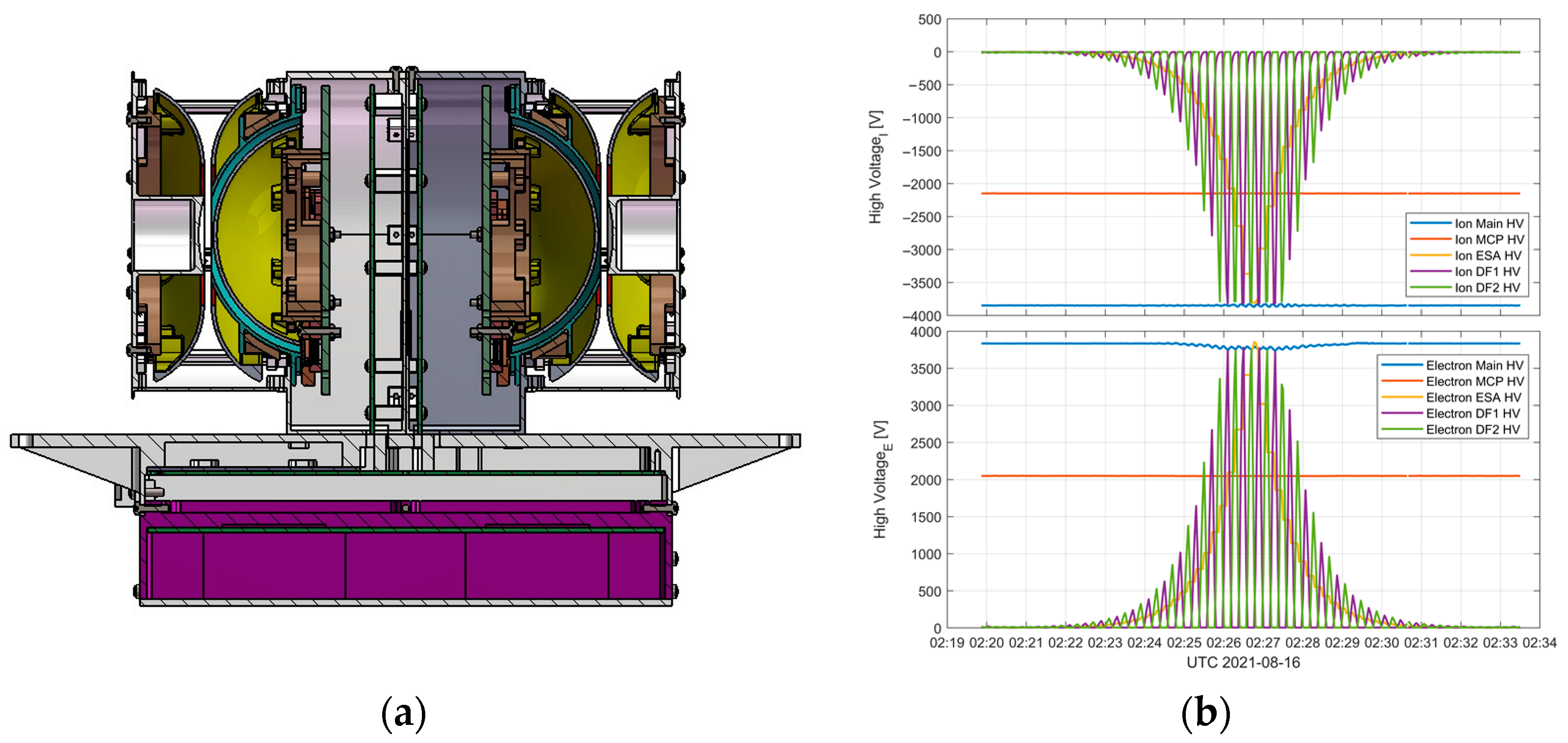
The PMA consists of an ion sensor and an electron sensor, which both obey the same detection principle, and are, respectively, composed of an electrostatic deflection part, an energy analyzer part (hemispherical electrostatic analyzer), a microchannel plate (MCP), anodes, and electronic parts. After ions or electrons pass through the electrostatic deflection system, they enter the hemispherical electrostatic analyzer consisting of inner and outer hemispheres. Under the selection of scanning bias, the ions or electrons of the corresponding energy pass through the slit between the inner and outer hemispheres and hit the rear MCP. After being amplified by the MCP, the charges are collected by the anode at the back end to generate charge pulses, which are processed and analyzed by the rear electronics to identify the energy spectral distribution and changes in the electrons and ions of the space plasma in different directions. The polar orbiting satellite is charged under the influence of space plasma. The charged satellite has a potential difference from its structural ground potential to space plasma. Space plasma can be considered as the absolute zero potential. The positively or negatively charged satellite as a whole accelerates or decelerates the incident ions and electrons. Figure 1b shows the high-voltage scan during the in-orbit test. The velocity variations of the ions and electrons, once obtained, may help invert the absolute potential of the satellite.
The PMA was installed on the -Z plane of the satellite, with its azimuth distributed along the ±X plane of the satellite. The design performances of the PMA are shown in Table 1 below). The X-axis of the satellite coordinate system indicates the direction of the satellite’s flight. The Y-axis points towards the sun. The Z-axis is defined as a cross product of the X-axis and Y-axis.

3. Ground-Based Calibration Experiment

The PMA directly measures the number of ions and electrons received by the sensor within different energy ranges and azimuth angles. The energy detection range of the ions and electrons corresponds to the measurable absolute charging potential on the satellite surface. To ensure the accuracy of the calibration experiment, we calibrated the detectable energy ranges and FOV of the ion sensor and the electron sensor separately in the ground-based calibration experiment and determined the electrostatic analyzer factor and the accuracy of the calibration experiment. The calibration experiments of the ion sensor and the electron sensor of the PMA were carried out using a standard ion/electron beam source, respectively. Figure 2 shows a photo of the PMA located in the calibration tank. The specific performances of the main calibration system and equipment are as follows.
Vacuum target chamber: Vacuum pressure < 1 × 10⁻⁴ Pa.
Electron beam source: Energy range of 30 eV~30 keV.
Ion beam source: Energy range of 30 eV~30 keV.
Vacuum turntable: The rotation covered the 180°× ± 45° FOV, with a positioning accuracy better than 0.1 mm for translation and better than 0.1° for rotation.
(1)
Detection energy range and the electrostatic analyzer factor (energy resolution)
The detection energy of the PMA is determined by the scanning voltage applied by the electrostatic analyzer. The number of detection energy channels corresponds to the number of scanning voltage steps. We set the number of scanning voltage steps of the electrostatic analyzer to 60 via the high-voltage module and set the same number of detection energy channels for the ion sensor and the electron sensor.
The two sensors of the PMA select the energy of the passing ions or electrons by applying varied positive or negative step scanning voltages V to the hemispherical electrostatic analyzer. The quantitative relationship between the energy of the selected charged particles E0 and the step scanning voltage V is presented in the following equation.
E 0 = k · V ,
where k is the electrostatic analyzer factor, which is determined by the structural characteristics of the electrostatic analyzer as an inherent parameter of the detector. We selected ion and electron beam sources of different levels of energy for the incidence, then obtained the distribution curves of the scanning voltage and the corresponding count values of the detector fitted to a Gaussian distribution. The voltage corresponding to the peak of the fitted curve can be substituted into Equation (1) to obtain the electrostatic analyzer factor k , and the energy resolution is represented by the FWHM ΔE/E of the peak.
The calibration of the electrostatic analyzer factor aimed to scan the voltage of the deflection plate of the electrostatic analyzer based on the ion source of the fixed energy. We found the electrostatic analyzer factor k by carrying out the calibration of the factor on multiple energy points and then linearly fitting it to Equation (1). The energy points involved in the ion sensor calibration were 3 keV, 5 keV, 10 keV, 15 keV; the energy points involved in the electron sensor calibration were 1 keV, 5 keV, 10 keV, 15 keV. Figure 3 shows the fitting results of the electrostatic analyzer factor of the ion/electron sensor. The electrostatic analyzer factor of the ion sensor was 8.03 ± 0.03, compared to 7.81 ± 0.02 in the case of the electron sensor. The scanning voltage of the electrostatic analyzer could reach between 3~4000 V. According to the fitting result of the electrostatic analyzer factor and Equation (1), the electrostatic analyzer factor of the ion sensor was 8.03 ± 0.03, and the measured electron energy range was 23.7 eV~31.6 keV.
The absolute charging potential on the satellite surface could be found by inversion based on the ion and electron energy spectra of the PMA. According to the detected energy ranges of the ions and electrons, the measured potential ranges of the PMA were −32.4 kV–24.3 V and +23.7 V~+31.6 kV.
(2)
Detection of the FOV and the geometric factor
The calibration of the FOV was carried out at the azimuth and elevation angles, as shown in Figure 4. The calibration of the FOV aimed to record the response of the instrument in different azimuth directions by scanning of the vacuum turntable in the azimuth direction.
A.
Calibration of the FOV at azimuth angles
For the ion/electron sensor, the FOV of 180° at the azimuth angles were divided into eight equal detection channels, each approx. 22.5°. Figure 4 shows the ground-based calibration results of the FOV at azimuth angles for the ion/electron sensor. It can be seen that the FOV of both sensors was 180°, the FOV of the eight detection channels was approx. 22.5° each, the measurement error of the azimuth angle was ±0.1°, determined by the repositioning accuracy of the turntable of the calibration system.
B.
Calibration of the FOV at elevation angles
For the FOV at the elevation angles of the ion/electron sensor, we selected the ion/electron incidence at different elevation angles by voltage scanning the upper and lower deflection plates of the deflection system. The ion and electron distributions at the elevation angles are shown in Figure 5a,b. By Gaussian fitting multiple ion and electron energy points at the elevation angles, the elevation angle of the ion sensor was determined to be 0.58° ± 0.13°, while the elevation angle of the electron sensor was 0.56° ± 0.02°.
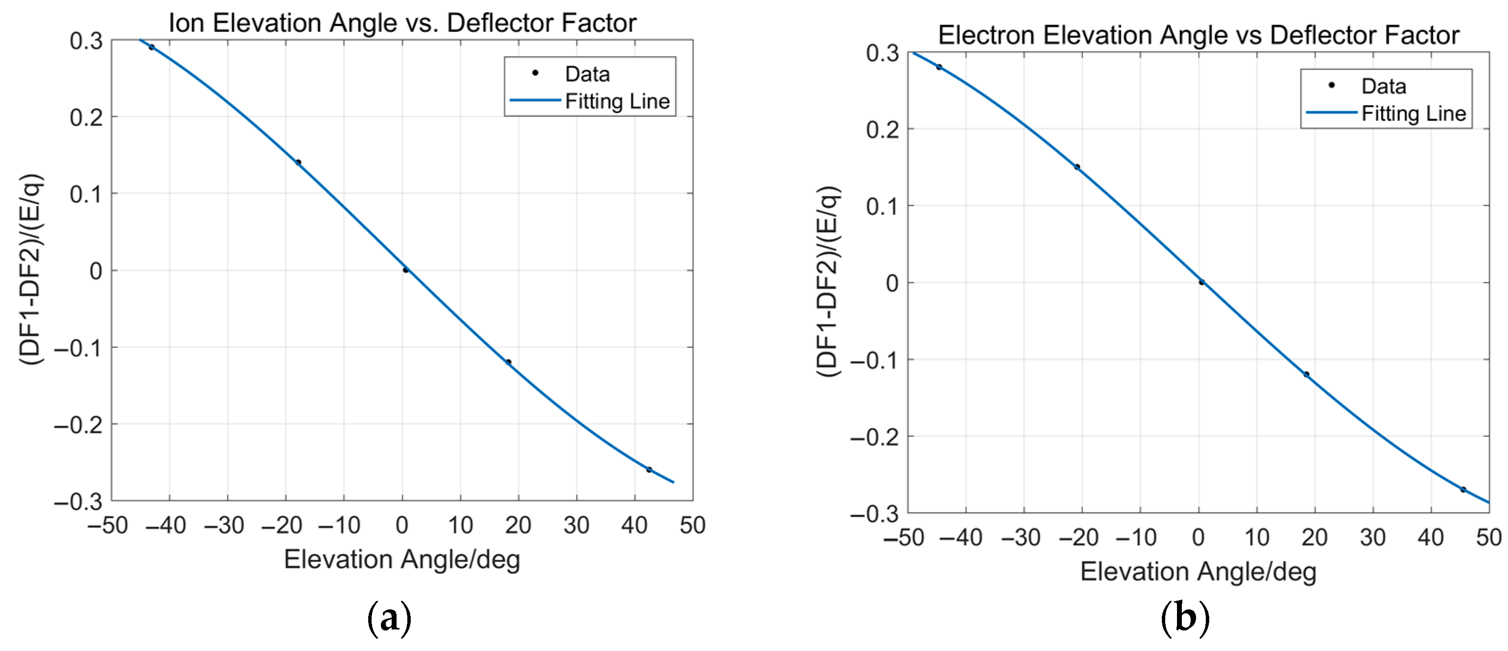
The deflection system constant represents the relationship between the voltage applied to the deflection plate and the measured FOV of the ion at elevation angles. The deflection system constant can be defined as follows.
R = V UP V LOW E / q
where VUP is the voltage of the upper deflection plate of the deflection system, VLOW is the voltage of the lower deflection plate of the deflection system, E is the measured ion/electron energy, and q is the particle charge number.
Based on the fixed energy and flux of the ion source, we set a fixed upper and lower deflection plate voltage and found the optimal direction of the ion incidence under this voltage configuration by scanning the rotated turntable. The turntable was aligned with the five elevation angles of the ion/electron sensor, which were, respectively, 43.0°, 18.0°, 1.0°, −18.0°, and −43.0° in the case of the ion sensor, and 45.0°, 20.0°, 1.0°, −20.0°, and −45.0° in the case of the electron sensor. To obtain their elevation angle scan curves, as shown in Figure 6, the horizontal coordinate was the elevation angle and the vertical ordinate was the deflection system constant. It can be seen that the FOV for both sensors at elevation angles reached ±45°.
(3)
Geometric factor
The calibration performances of the PMA are shown in Table 2.

4. In-Orbit Test and Preliminary Observations

The PMA directly measures the number of ions and electrons received by the sensor within different energy ranges and azimuth angles. The energy detection range of the ions and electrons corresponds to the measurable absolute charging potential on the satellite surface. To ensure the accuracy of the calibration experiment, we calibrated the detectable energy ranges and FOV of the ion sensor and the electron sensor separately in the ground-based calibration experiment and determined the electrostatic analyzer factor and the accuracy of the calibration experiment. The calibration experiments of the ion sensor and the electron sensor of the PMA were carried out using a standard ion/electron beam source. Figure 2 shows a photo of the PMA located in the calibration tank. The specific performances of the main calibration system and equipment are as follows.

4.1. Characteristics of Plasma Distribution in a Relatively Quiet Space Environment

After launching the FY-3E, the PMA switched to the continuous detection mode on 15 August 2021 and measured the differential flux in the direction of space plasma of the electrons and ions at an orbital height of 836 km.
Figure 7 illustrates the spatial flux distributions, profiles of the elevation angle-normalized flux, and profiles of energy-normalized flux of the ions and electrons in low Earth orbit during a quiet space environment period. These graphical representations highlight the typical behavior and properties of plasma in the orbital region. This indicated that the PMA recorded higher fluxes of ions and electrons in the polar high-latitude region and the radiation belt anomaly region. The central axis of the ion sensor’s elevation angle was nearly parallel to the magnetic field lines, indicating that the normalized flux at different elevation angles corresponded to the pitch angle of the electrons and ions. The results suggested that there was a stronger anisotropy in the distribution of electrons compared to ions. The profiles for the electron and ion distributions complied with the power-law spectrum f(E) = A × E−v, where the energy spectrum index (v) for the electrons was 1.07 and for the ions was 0.97. The statistical results indicated that the intensity of the differential flux of the ions and electrons in the mid-to-high latitudes ranged from 105 to 109 (cm−2 s−1 sr−1 keV−1). Among them, the daily average flux of the electrons was higher than that of the ions, and their distribution ranges were similar. These results were consistent with the observation data from the precipitating electron and ion spectrometer of the Defense Meteorological Satellite Program (DMSP) [10] at an altitude of 830 km in a sun-synchronous orbit (https://cdaweb.gsfc.nasa.gov/ (accessed on 26 August 2021)).

4.2. Characteristics of Plasma Distribution during a Geomagnetic Storm

During the early phase of the satellite’s orbit, a moderate geomagnetic storm occurred at the end of August 2021, where a Dst index reached −82 nT on the 27th within 9 h after the onset and entered the recovery phase on the 28th. In Figure 8 and Figure 9, we provide the variations in the total counts of electrons and ions with latitudes for the orbital space before and after the occurrence of the geomagnetic storm from 26–28 August 2021. It can be observed that precipitating particles were mainly distributed in the mid-to-high latitudes of the Northern and Southern hemispheres. Since the FY-3E is a dawn–dusk satellite, the left panels of Figure 8 and Figure 9 represent the observations from local time 0–10 am (dawn side), while the right panels represent the observations from local time 12–22 pm (dusk side). The results of Figure 8 and Figure 9 were obtained by interpolating all the in situ observation data from each satellite orbit of one day (approximately 14–15 orbits around the Earth). It can be observed that there was a significant difference between the Northern and Southern hemispheres in terms of background ions compared to electrons. The flux of background ions in the Northern Hemisphere was noticeably higher than that in the Southern Hemisphere. As shown in Figure 8 and Figure 9, at this orbital altitude, there were differences in the distribution of ions and electrons depending on the local time, with a more significant local time difference observed for ions compared to electrons. The observations from the three days before and after the geomagnetic storm in Figure 8 and Figure 9 indicated that the moderate geomagnetic storm primarily affected charged particles in the mid-to-high latitudes of the Northern and Southern hemispheres. During the peak of the storm, the range of precipitating particles located in the mid-to-high latitudes of both hemispheres increased. In the Southern Hemisphere, the lowest latitude of the distribution range extended from −50 degrees to −40 degrees, while in the Northern Hemisphere, it extended from 60 degrees to 50 degrees. A significant asymmetry in the flux and distribution of electrons and ions in the mid-to-high latitude precipitating belts between the Northern and Southern hemispheres was demonstrated. Outside the radiation belt anomaly region, the electron and ion flux in the Northern Hemisphere was generally higher than that in the Southern Hemisphere. The geomagnetic storm did not significantly affect the thermal plasma in the radiation belt anomaly region. We analyzed the daily average flux of electrons and ions from the 26th to the 28th, and the results showed that on the 27th, the daily average flux of electrons increased by approximately 5%, and the flux of ions increased by approximately 2.5%. On the 28th, both the electron and ion fluxes decreased by approximately 5% and 2.5%, respectively. The increase in the daily average electron flux was more significant than that of the ions. An increase in the precipitating particle flux and distribution area can heat the thermosphere, elevate the atmospheric density in the mid-to-high latitudes of both hemispheres, increase the ionization rate of the ionosphere, and cause disturbances in the ionosphere.

5. Conclusions and Discussion

The FY-3E PMA is China’s first instrument for detecting the thermal plasma environment in polar satellite orbits. This study introduced the ground calibration, in-orbit performance, and preliminary observation results of the PMA. Before the satellite launch, the PMA underwent ground calibration tests in laboratory conditions to evaluate the detection energy range, FOV, and accuracy of the instruments. The detection accuracy and geometric factors were determined, showing that the detection performance met the design requirements, and the data were reliable and effective for the satellite’s absolute potential calculation.
During the orbit performance phase, the PMA obtained thermal plasma ions and electrons in typical spatial regions along the satellite’s orbit, especially the characteristic distribution of precipitating particles in the mid-to-high latitude regions of the Northern and Southern hemispheres, which was consistent with the observations of the DMSP. The observations indicated that precipitating particles were mainly distributed in the mid-to-high latitude regions of the Northern and Southern hemispheres, with differential flux intensities of ions and electrons ranging from 105 to 109 (cm−2 s−1 sr−1 keV−1). The daily average flux of electrons was higher than that of the ions, and both the electrons and ions followed a power-law spectrum distribution. The distributions of the electrons and ions exhibited angular scattering characteristics, with the electrons showing a stronger anisotropy than the ions. Differences in the local time were observed in the distribution of the ions and electrons, with a more significant local time difference for the ions on the dawn and dusk sides. These observational characteristics were consistent with the general features and patterns of plasma in this spatial region.
The observation results before and after the geomagnetic storm indicated that the main impact of the storm occurred in mid-to-high latitude thermal plasma regions in both hemispheres. During the peak of the storm, the spatial region of the particle precipitation extended toward lower latitudes by approximately 10 degrees in the mid-to-high latitude regions of the Northern and Southern hemispheres. The increase in the electron flux was more significant than that of the ions. The effects of precipitating particles on the thermosphere and ionosphere during geomagnetic storms require further study.
The ground calibration and in-orbit performance results demonstrated the scientific validity of the PMA scientific data. The FY-3E PMA has the capability for monitoring the thermal plasma environment in real time along the satellite’s orbit, providing critical data for space weather forecasting research and in-orbit safety assurance for satellites.

Author Contributions

Conceptualization ideas, visualization and writing—original draft preparation, X.W. and D.D.; data calibration, B.S., B.L. and Z.T.; formal analysis, A.Z. and L.K.; writing—review and editing, D.D., A.Z. and L.K.; resources, Y.Y. and P.Z.; project administration, X.Z., J.W., C.H. and J.L. All authors have read and agreed to the published version of the manuscript.

Funding

This research was funded by the Strategic Priority Research Program of the Chinese Academy of Sciences (Grant No. XDA17010303), the National Natural Science Foundation of China (NSFC, Grant No. 41204128), and the Foundation of the Key Laboratory of National Defense Science and Technology, Chinese Academy of Sciences (CXJJ-22S031).

Institutional Review Board Statement

Not applicable.

Informed Consent Statement

Not applicable.

Data Availability Statement

The data are not publicly available since the satellite was in the in-orbit test phase during the data period referenced in this article. The data presented in this study can be obtained upon request from the corresponding authors. The space weather Dst indices are available at https://wdc.kugi.kyoto-u.ac.jp/ (accessed on 27 September 2023).

Acknowledgments

This work was supported by the Key Laboratory of Space Weather, National Satellite Meteorological Center, China Meteorological Administration. The authors thank the management and technical support of the Shanghai Institute of Satellites Engineering for their efforts in creating the excellent satellite conditions. The available data websites have largely promoted our work. In particular, we offer our sincere thanks to the reviewers for their valuable and helpful comments.

Conflicts of Interest

The authors declare no conflict of interest.

References

  1. Galand, M.; Richmond, A.D. Ionospheric Electrical Conductances Produced by Auroral Proton Precipitation. J. Geophys. Res. 2001, 106, 117–125. [Google Scholar] [CrossRef]
  2. Baker, D.N. Coupling between the Solar Wind, Magnetosphere, Ionosphere and Neutral Atmosphere; University of Colorado: Boulder, CO, USA, 2004. [Google Scholar]
  3. Gledhill, J.A. Aeronomic Effects of the South Atlantic Anomaly. Rev. Geophys. Space Phys. 1976, 14, 173–187. [Google Scholar] [CrossRef]
  4. Hardy, D.A.; Gussenhoven, M.S.; Brautigam, D. A statistical model of auroral ion precipitation. J. Geophys. Res. 1989, 94, 370–392. [Google Scholar] [CrossRef]
  5. Li, X.; Baker, D.N.; Elkington, S.; Temerin, M.; Reeves, G.D.; Belian, R.D.; Blake, J.B.; Singer, H.J.; Peria, W.; Parks, G. Energetic Particle Injections in the Inner Magnetosphere as a Response to an Inter planetary Shock. J. Atmos. Sol. Terr. Phys. 2003, 65, 233–244. [Google Scholar] [CrossRef]
  6. Grankin, D.; Mironova, I.; Bazilevskaya, G.; Rozanov, E.; Egorova, T. Atmospheric Response to EEP during Geomagnetic Disturbances. Atmosphere 2023, 14, 273. [Google Scholar] [CrossRef]
  7. Mironova, I.A.; Aplin, K.L.; Arnold, F.; Bazilevskaya, G.A.; Harrison, R.G.; Krivolutsky, A.A.; Nicoll, K.A.; Rozanov, E.V.; Turunen, E.; Usoskin, I.G. Energetic Particle Influence on the Earth’s Atmosphere. Space Sci. Rev. 2015, 194, 1–96. [Google Scholar] [CrossRef]
  8. Evans, D.S.; Greer, M.S. Polar Orbiting Environmental Satellite Space Environment Monitor-2: Instrument Descriptions and Archive Data Documentation; (NOAA Technical Memorandum OAR SEC-93); NOAA: Boulder, CO, USA, 2000.
  9. Sibanda, P. Particle Precipitation Effects on the South African Ionosphere. Master’s Thesis, Rhodes University, Makhanda, South Africa, 2006. [Google Scholar]
  10. Redmon, R.J.; Denig, W.F.; Kilcommons, L.M.; Knipp, D.J. New DMSP database of precipitating auroral electrons and ions. J. Geophys. Res. Space Phys. 2017, 122, 9056–9067. [Google Scholar] [CrossRef] [PubMed]
Figure 1. Structure and in-orbit parameter diagram of the PMA. (a) The structure diagram of the PMA. (b) The high-voltage scan in the in-orbit test.
Atmosphere 14 01665 g001
Figure 2. PMA in the calibration tank.
Atmosphere 14 01665 g002
Figure 3. The fitting result of the electrostatic analyzer factor of the ion/electron sensor. (a) Ions; (b) electrons.
Atmosphere 14 01665 g003
Figure 4. FOV at the azimuth angles of the eight channels of the ion/electron sensor. (a) Ions; (b) electrons.
Atmosphere 14 01665 g004
Figure 5. Ion and electron elevation angle distributions. (a) Ions; (b) electrons.
Atmosphere 14 01665 g005
Figure 6. Elevation angle scans of the ion/electron sensor. (a) Ions; (b) electrons.
Atmosphere 14 01665 g006
Figure 7. The typical spatial flux distributions, elevation angle-normalized flux profiles, and energy-normalized flux profiles of electrons and ions at a low Earth orbit altitude. (ad) The flux distribution of electrons and ions at the two hemispheres along the satellite trajectory on 26 August 2021. (e,f) The elevation angle-normalized flux profiles of electrons and ions on 26 August 2021. (g,h) The energy-normalized daily average distribution curves of ions and electrons. (a,b,e,g) Electrons; (c,d,f,h) ions.
Atmosphere 14 01665 g007
Figure 8. The spatial distribution of electron fluxes in the 0.3–30 keV underwent changes in both the Northern and Southern hemispheres before and after the geomagnetic storm for three days. (a) 26 August 2021; (b) 27 August 2021; (c) 28 August 2021.
Atmosphere 14 01665 g008
Figure 9. The spatial distribution of ion fluxes in the 0.3–30 keV underwent changes in both the Northern and Southern hemispheres before and after the geomagnetic storm for three days. (a) 26 August 2021; (b) 27 August 2021; (c) 28 August 2021.
Atmosphere 14 01665 g009
Table 1. The design performances of the PMA.
Energy Range300~3000 eV
Energy resolution15 eV
Channel2
Table 2. The design performances of the PMA.
ItemResult
Energy rangeIon: 24.3 eV~32.4 keV
Electron: 23.7 eV~31.6 keV
Energy resolution10 eV
Observation channel16 × 6
Detection accuracyAzimuth: ≤0.44%
Ion energy: ≤3.53%
Ion elevation angle: ≤10.00%
Electron energy: ≤5.31%
Electron elevation angle: ≤10.00%
Disclaimer/Publisher’s Note: The statements, opinions and data contained in all publications are solely those of the individual author(s) and contributor(s) and not of MDPI and/or the editor(s). MDPI and/or the editor(s) disclaim responsibility for any injury to people or property resulting from any ideas, methods, instructions or products referred to in the content.

