
Aerodynamic Shape Optimization of a Square Cylinder with Multi-Parameter Corner Recession Modifications


Abstract
:1. Introduction
2. Description of the Aerodynamic Shape Optimization Problem
2.1. Mathematical Model of the Aerodynamic Shape Optimization
- (1)
- The objective functions should quantitatively represent the aerodynamic performance of the cylinder, and change of the design variables should significantly impact the objective functions’ values.
- (2)
- To ensure the surrogate model’s optimization accuracy, the problem needs to be simplified by using a limited number of objective functions.
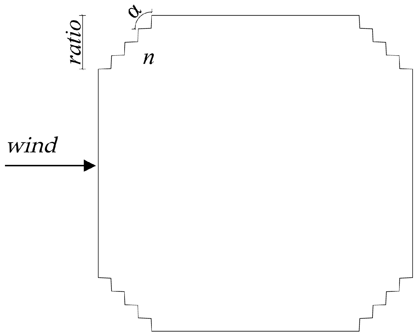
2.2. Geometric Parameters and Design Space
3. Solution Strategy
3.1. Proposal of the Surrogate Model Updating-Based Aerodynamic Shape Optimization Framework
- (1)
- (2)
- Based on the relation between input variables (geometric parameters) and output variables (aerodynamic force coefficients) of the initial sample points, the training set, validation set, and test set were allocated according to a certain proportion, and the GA-GRNN surrogate model was trained continuously until the test set verified that its prediction accuracy met the requirements.
- (3)
- To search for the objective functions (minimum CD and CσL) in the whole design space, based on the GA-GRNN surrogate model, the multi-objective non-dominated sorting genetic algorithm (NSGA-II) was adopted for the optimization, and the Pareto optimal front solutions were obtained, in which some of the solutions were selected for CFD verification.
- (4)
- If the prediction accuracy of the selected Pareto optimal front solutions satisfied the convergence criteria, the Pareto optimal front samples were added to the training samples, and a new round of training and optimization was carried out for the GA-GRNN surrogate model. The optimization accuracy was continuously improved through iterative updating until the convergence criteria were met, and finally the optimization solutions were acquired.
3.2. CFD Simulation
- (1)
- The paper aimed to search for the cross-sectional configuration with the most favorable aerodynamics, and the specific numerical value of the section aerodynamic coefficient is not strictly required. Previous 2D and 3D numerical simulation studies show that the influence law of section shape change on the aerodynamic performance of the structure obtained by the two methods is consistent, but there are only numerical differences [3,4,24].
- (2)
- A large amount of CFD calculation is required in the optimization process, and the 3D numerical simulation is time-consuming, so it is very difficult to realize in the existing conditions. In addition, the method of simplifying the 3D model to the 2D model for aerodynamic shape optimization has been extended to the field of civil engineering [17].
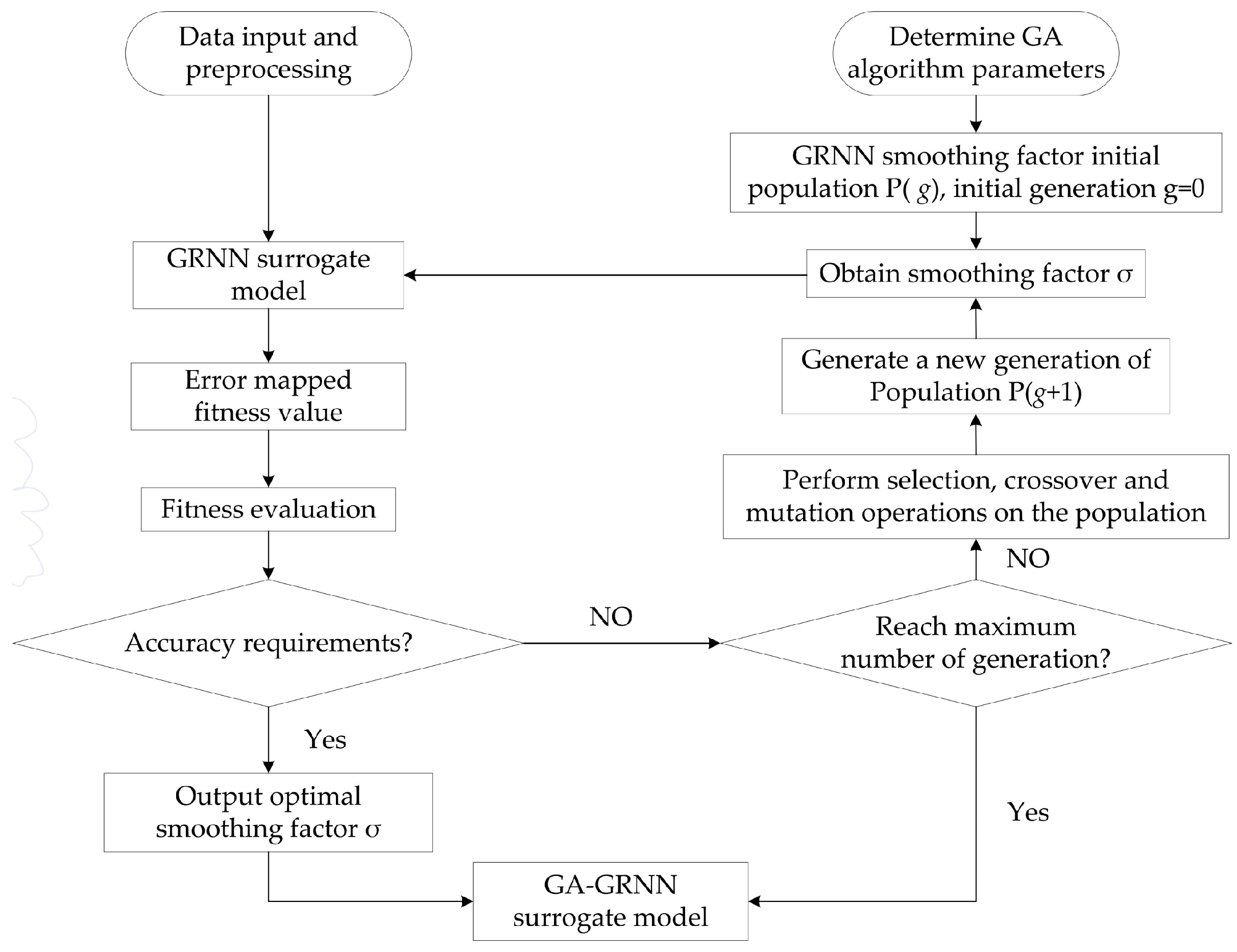
3.3. GA-GRNN Surrogate Model
3.4. Convergence Criteria for the Aerodynamic Shape Optimization
4. Results and Analysis
4.1. Aerodynamic Shape Optimization Results
4.2. Aerodynamic Force Coefficients and Strouhal Number St
4.3. Wind Pressure Coefficients Distributions
4.4. Time-Averaged Flow Field
- (1)
- When compared with the benchmark section S, the wake lengths L of the sections M1~M8 were significantly increased, and the maximum L was 2.41D for the section M6. Increase of the wake length can be attributed to the backward shift of the separation point caused by the corner recession modification, and the vortices in the wake region were far away from the leeward surface, which led to a small absolute value of the mean wind pressure coefficient Cp on the leeward surface. Such a decrease of wind pressure resulted in reduction of the pressure drag of the corner recession sections, and thus the mean drag coefficient CD.
- (2)
- When compared with the benchmark section S, the corner recession correction made the separation point of the optimal sections M1~M8 move backwards, restraining the development of vortex shedding in the wake and deflecting the separated shear layer towards the side surfaces [4,7,32], and thus the width of the recirculation region of the sections M1~M8 was significantly reduced. The minimum wake width W was 1.09D for the section M1. As a result, the vortex shedding intensity was restrained, and the root mean square lift coefficient CσL was significantly reduced.
4.5. Instantaneous Flow Field
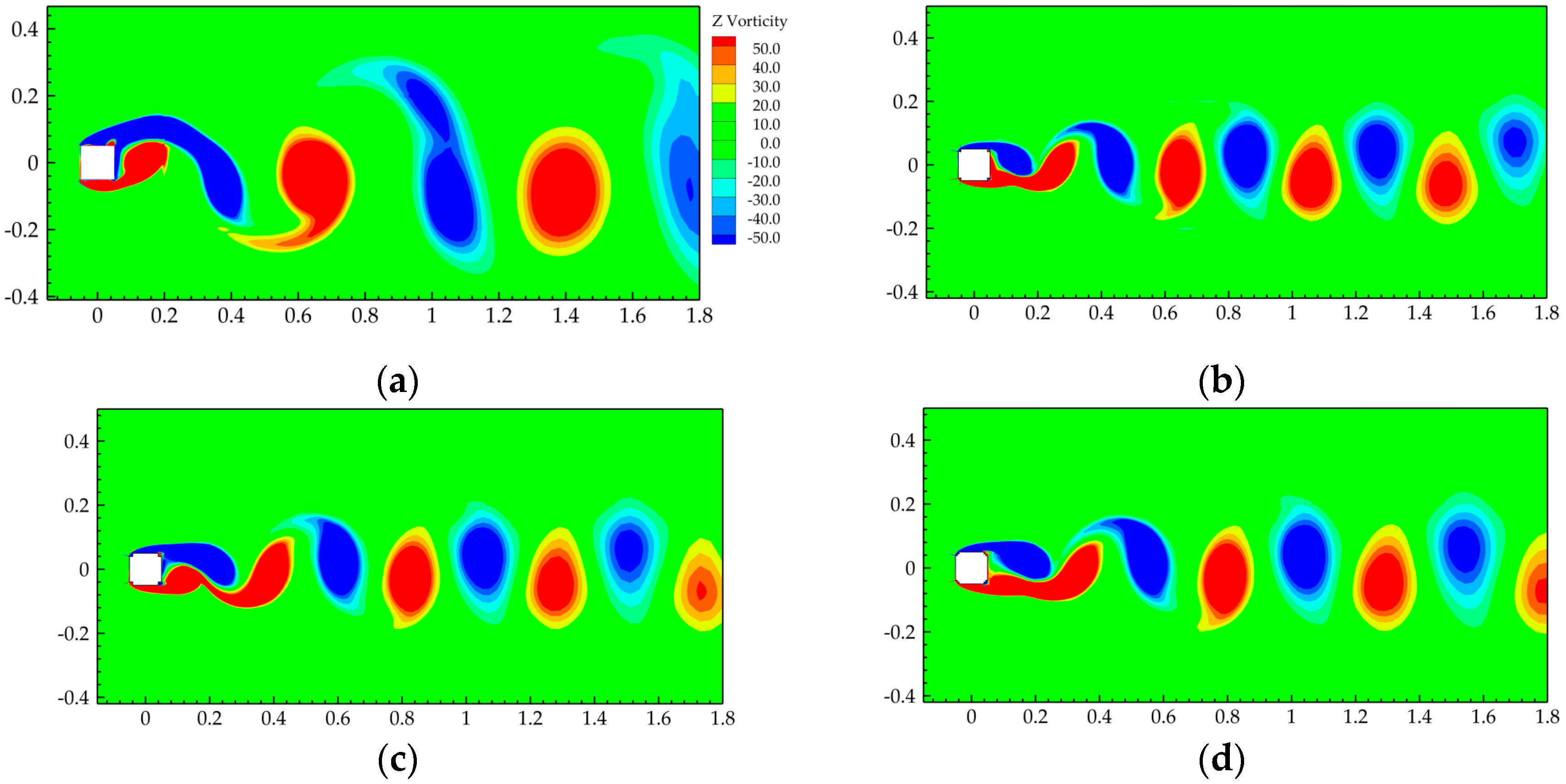
- (1)
- There were plenty of vortex structures around the sections. The lower side was dominated by positive vortices, while negative vortices dominated the upper side. With vortices’ formation and development in the downstream, alternating vortex shedding occurred in the wake region, and the corner recession modification did not change the vortex development trend.
- (2)
- When compared with the benchmark section S, the width of vortex street in the wake region of the sections M1~M8 was significantly reduced, and the reason can be attributed to the corner recession modification promoting the reattachment of the separated shear layer, and the separated flows being brought closer to the side surface due to the entrainment of small vortices, accompanied by constraint of the separation angles, thus significantly reducing the mean drag coefficient CD. It can be concluded that the narrow vortex street width in the wake area is the main reason for the decrease in CD surfaces [7].
- (3)
- The length scales of vortex shedding for the sections M1~M8 were reduced when compared with the benchmark section S, and the number of vortex sheds increased. It can be concluded that the corner recession modification can suppress the vortex shedding to a certain extent, reduce the intensity of vortex shedding, and accelerate the vortex shedding with a larger Strouhal number St (vortex shedding frequency). Therefore, the CσL of the sections M1~M8 were significantly reduced.
5. Conclusions
- (1)
- In the whole process of aerodynamic shape optimization, a total of 74 sample points were computed by the CFD simulation, accounting for 5.69% of the total number of samples (1300) in the whole design space. Additionally, the aerodynamic shape optimization results based on the GA-GRNN surrogate model with three or four design parameters were highly consistent. It is concluded that the present GA-GRNN surrogate model updating-based multi-objective optimization framework can significantly improve the optimization efficiency in solving complex engineering problems, while still ensuring the prediction accuracy. The proposed multi-objective optimization framework in this study can provide an important reference for the aerodynamic shape optimization of building structures and relevant studies.
- (2)
- Compared with the benchmark section S, the mean drag coefficient CD and root mean square lift coefficient CσL of the sections M1~M6 were significantly reduced, and the maximum values of the reduction coefficients CDR and CσLR could reach 0.457 and 0.928, which appeared in the sections M1 and M4, respectively. The corner recession modifications significantly increased the Strouhal number St of the square cylinder, and the maximum St was 0.214 for the section M1. The increase of St will lead to larger critical wind speed so as to postpone the vortex shedding resonance of flexible supertall buildings.
- (3)
- Based on the analysis of the flow structures around the optimal sections M1~M8, it is concluded that the corner recession modifications can postpone the flow separation and deflects the separated shear layer towards the side surfaces, which leads to significant elongation of the wake length and reduction of the width of the recirculation region, and thus the CD is reduced. Besides, the corner recession modifications can suppress the intensity of vortex shedding and increase the number of shedding vortices, and accelerate the vortex shedding with a larger Strouhal number St (vortex shedding frequency), and thus the CσL of the sections M1~M8 are significantly reduced.
Author Contributions
Funding
Institutional Review Board Statement
Informed Consent Statement
Data Availability Statement
Acknowledgments
Conflicts of Interest
References
- Kareem, A.; Kijewski, T.; Tamura, Y. Mitigation of motions of tall buildings with specific examples of recent applications. Wind Struct. 1999, 2, 201–251. [Google Scholar] [CrossRef] [Green Version]
- Irwin, P.A. Bluff body aerodynamics in wind engineering. J. Wind Eng. Ind. Aerodyn. 2008, 96, 701–712. [Google Scholar] [CrossRef]
- Zheng, C.R.; Xie, Y.; Khan, M.; Wu, Y.; Liu, J. Wind-induced responses of tall buildings under combined aerodynamic control. Eng. Struct. 2018, 175, 86–100. [Google Scholar] [CrossRef]
- Zheng, C.R.; Wang, Z.Y.; Zhang, J.; Wu, Y.; Jin, Z.; Chen, Y. Effect of the combined aerodynamic control on the amplitude characteristics of wind loads on a tall building. Eng. Struct. 2021, 245, 112967. [Google Scholar] [CrossRef]
- Kwok, K.C.S.; Wilhelm, P.A.; Wilkie, B.G. Effect of edge configuration on wind-induced response of tall buildings. Eng. Struct. 1988, 10, 135–140. [Google Scholar] [CrossRef]
- Kawai, H. Effect of corner modifications on aeroelastic instabilities of tall buildings. J. Wind Eng. Ind. Aerodyn. 1998, 74, 719–729. [Google Scholar] [CrossRef]
- Tamura, T.; Miyagi, T. The effect of turbulence on aerodynamic forces on a square cylinder with various corner shapes. J. Wind Eng. Ind. Aerodyn. 1999, 83, 135–145. [Google Scholar] [CrossRef]
- Tse, K.T.; Hitchcock, P.A.; Kwok, K.C.; Thepmongkorn, S.; Chan, C.M. Economic perspectives of aerodynamic treatments of square tall buildings. J. Wind Eng. Ind. Aerodyn. 2009, 97, 455–467. [Google Scholar] [CrossRef]
- Tanaka, H.; Tamura, Y.; Ohtake, K.; Nakai, M.; Kim, Y.C. Experimental investigation of aerodynamic forces and wind pressures acting on tall buildings with various unconventional configurations. J. Wind Eng. Ind. Aerodyn. 2012, 107, 179–191. [Google Scholar] [CrossRef]
- Zhang, Z.; Quan, Y.; Gu, M.; Xiong, Y. Effects of corner recession modification on aerodynamic coefficients of square high-rise buildings. China Civ. Eng. J. 2013, 46, 58–65. [Google Scholar]
- Zhang, Z.W.; Quan, Y.; Gu, M.; Xiong, Y. Effects of corner chamfering and rounding modification on aerodynamic coefficients of square tall buildings. China Civ. Eng. J. 2013, 46, 12–20. [Google Scholar]
- Zheng, C.R.; Zhang, J.T.; Zhang, Z.D. Experimental investigation on characteristics of mean wind loads of high-rise buildings controlled by corner recession and air-suction. J. Build. Struct. 2016, 37, 125–131. [Google Scholar]
- Kim, Y.; Kanda, J. Effects of taper and set-back on wind force and wind-induced response of tall buildings. Wind Struct. 2010, 13, 499–517. [Google Scholar] [CrossRef]
- Kim, Y.C.; Kanda, J. Wind pressures on tapered and set-back tall buildings. J. Fluids Struct. 2013, 39, 306–321. [Google Scholar] [CrossRef]
- Kim, Y.C.; Tamura, Y.; Tanaka, H.; Ohtake, K.; Bandi, E.K.; Yoshida, A. Wind-induced responses of super-tall buildings with various atypical building shapes. J. Wind Eng. Ind. Aerodyn. 2014, 133, 191–199. [Google Scholar] [CrossRef]
- Deng, T.; Yu, X.; Xie, Z. Aerodynamic measurements of across-wind loads and responses of tapered super high-rise buildings. Wind Struct. 2015, 21, 331–352. [Google Scholar] [CrossRef]
- Bernardini, E.; Spence, S.M.J.; Wei, D.; Kareem, A. Aerodynamic shape optimization of civil structures: A CFD-enabled Kriging-based approach. J. Wind Eng. Ind. Aerodyn. 2015, 144, 154–164. [Google Scholar] [CrossRef] [Green Version]
- Elshaer, A.; Bitsuamlak, G.; Damatty, A.E. Enhancing wind performance of tall buildings using corner aerodynamic optimization. Eng. Struct. 2017, 136, 133–148. [Google Scholar] [CrossRef]
- Elshaer, A.; Bitsuamlak, G. Multiobjective aerodynamic optimization of tall building openings for wind-induced load reduction. J. Struct. Eng. 2018, 144, 04018198. [Google Scholar] [CrossRef]
- Li, Y.G.; Zhang, M.Y.; Li, Y.; Li, Q.S.; Liu, S.J. Experimental study on wind load characteristics of high-rise buildings with opening. Struct. Des. Tall Spec. 2020, 29, e1734. [Google Scholar]
- Davenport, A.G. The response of six building shapes to turbulent wind. Philos. Trans. R. Soc. Lond. 1971, 269, 385–394. [Google Scholar]
- Cao, H.L.; Quan, Y.; Gu, M. Along-wind aerodynamic damping of high-rise buildings with aerodynamically modified square cross-sections. J. Vib. Shock 2012, 31, 84–89. [Google Scholar]
- Sun, Q.; Zhou, Z.Y.; Hu, C.X.; Qing, P.; Huang, D.M. Numerical aerodynamic shape optimization of streamlined box. J. Harbin Inst. Technol. 2021, 53, 93–100. [Google Scholar]
- Wang, Z.Y.; Zheng, C.R.; Joshua, A.M.; Wu, Y. Aerodynamic shape optimization of a square supertall building with corner recession based on Surrogate model. China Civ. Eng. J. 2022, 1–12. [Google Scholar] [CrossRef]
- Jin, R.C.; Chen, W.; Sudjianto, A. An efficient algorithm for constructing optimal design of computer experiments. J. Stat. Plan. Inference 2005, 134, 268–287. [Google Scholar] [CrossRef]
- Jourdan, A.; Franco, J. Optimal Latin hypercube designs for the Kullback-Leibler criterion. Asta-Adv. Stat. Anal. 2010, 94, 341–351. [Google Scholar] [CrossRef]
- Vidya, S.; Janani, E.S.V. Tabu search algorithm based general regression neural network for long term wind speed predictions. Automatika 2020, 61, 657–669. [Google Scholar] [CrossRef]
- Cheng, M.; Jiang, P.; Hu, J.X.; Shu, L.; Zhou, Q. A multi-fidelity surrogate modeling method based on variance-weighted sum for the fusion of multiple non-hierarchical low-fidelity data. Struct. Multidiscip. Optim. 2021, 64, 3797–3818. [Google Scholar] [CrossRef]
- Ulaganathan, S.; Couckuyt, I.; Ferranti, F.; Laermans, E.; Dhaene, T. Performance study of multi-fidelity gradient enhanced. Struct. Multidiscip. Optim. 2015, 51, 1017–1033. [Google Scholar] [CrossRef] [Green Version]
- Miyashita, K.; Katagiri, J.; Nakamura, O.; Ohkuma, T.; Tamura, Y.; Itoh, M.; Mimachi, T. Wind-induced response of high-rise buildings: Effects of corner cuts or openings in square buildings. J. Wind Eng. Ind. Aerodyn. 1993, 50, 319–328. [Google Scholar] [CrossRef]
- Du, X.Q.; Tian, X.X.; Ma, W.Y.; Li, E.D. Effects of rounded corner on aerodynamics of square cylinders and its flow mechanisms. Chin. J. Appl. Mech. 2018, 50, 1013–1023. [Google Scholar]
- Sharma, A.; Mittal, H.; Gairola, A. Mitigation of wind load on tall buildings through aerodynamic modifications: Review. J. Build. Eng. 2018, 18, 180–194. [Google Scholar] [CrossRef]


| Type | Number | Ratio | n | α | CD | CσL |
|---|---|---|---|---|---|---|
| Training set | 1 | 1 | 65 | 3 | 1.901 | 1.513 |
| 2 | 2 | 80 | 4 | 1.802 | 1.428 | |
| 3 | 3 | 105 | 2 | 1.666 | 1.257 | |
| 4 | 3 | 75 | 2 | 1.691 | 1.321 | |
| 5 | 4 | 110 | 4 | 1.555 | 1.033 | |
| 6 | 5 | 105 | 3 | 1.346 | 0.493 | |
| 7 | 6 | 65 | 3 | 1.189 | 0.270 | |
| 8 | 6 | 90 | 4 | 1.161 | 0.171 | |
| 9 | 6 | 70 | 3 | 1.180 | 0.182 | |
| 10 | 7 | 90 | 4 | 1.189 | 0.163 | |
| 11 | 8 | 85 | 3 | 1.148 | 0.146 | |
| 12 | 9 | 115 | 1 | 1.094 | 0.236 | |
| 13 | 10 | 100 | 4 | 1.189 | 0.149 | |
| 14 | 10 | 95 | 1 | 1.104 | 0.194 | |
| 15 | 11 | 85 | 5 | 1.202 | 0.157 | |
| 16 | 11 | 80 | 2 | 1.186 | 0.221 | |
| 17 | 12 | 65 | 5 | 1.160 | 0.134 | |
| 18 | 13 | 95 | 3 | 1.233 | 0.150 | |
| 19 | 14 | 90 | 2 | 1.271 | 0.191 | |
| 20 | 15 | 110 | 3 | 1.254 | 0.213 | |
| 21 | 15 | 90 | 2 | 1.256 | 0.132 | |
| 22 | 15 | 115 | 3 | 1.245 | 0.179 | |
| 23 | 16 | 75 | 3 | 1.274 | 0.166 | |
| 24 | 17 | 70 | 2 | 1.292 | 0.143 | |
| 25 | 18 | 105 | 4 | 1.246 | 0.176 | |
| 26 | 19 | 70 | 5 | 1.278 | 0.208 | |
| 27 | 19 | 100 | 2 | 1.352 | 0.233 | |
| 28 | 20 | 115 | 3 | 1.286 | 0.195 | |
| Validation set | 29 | 2 | 110 | 1 | 1.802 | 1.430 |
| 30 | 5 | 80 | 4 | 1.382 | 0.307 | |
| 31 | 7 | 85 | 5 | 1.206 | 0.173 | |
| 32 | 9 | 60 | 5 | 1.178 | 0.123 | |
| 33 | 12 | 120 | 1 | 1.148 | 0.210 | |
| 34 | 14 | 95 | 1 | 1.179 | 0.204 | |
| 35 | 16 | 100 | 2 | 1.315 | 0.238 | |
| 36 | 18 | 75 | 4 | 1.264 | 0.191 | |
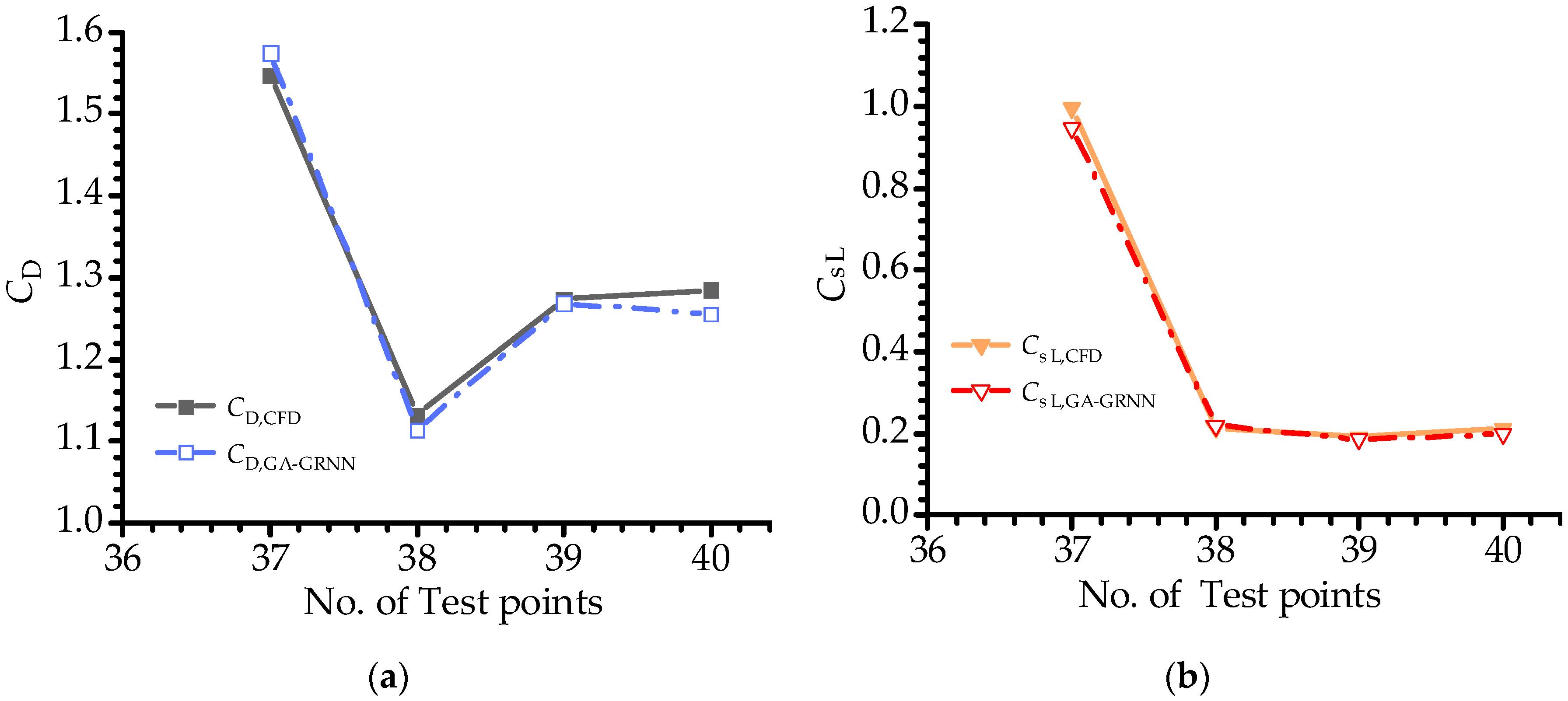
| Test set | 37 | 4 | 75 | 2 | 1.546 | 0.996 |
| 38 | 8 | 120 | 2 | 1.132 | 0.214 | |
| 39 | 13 | 60 | 4 | 1.273 | 0.191 | |
| 40 | 17 | 105 | 4 | 1.285 | 0.211 |
| Aerodynamic Force Coefficients | MAE | RMSE | R2 |
|---|---|---|---|
| CD | 0.032 | 0.023 | 0.975 |
| CσL | 0.061 | 0.044 | 0.984 |
| Typical Sections | CD | CσL | St |
|---|---|---|---|
| M1 | 1.033 | 0.235 | 0.216 |
| M9 | 1.037 | 0.228 | 0.214 |
Publisher’s Note: MDPI stays neutral with regard to jurisdictional claims in published maps and institutional affiliations. |
© 2022 by the authors. Licensee MDPI, Basel, Switzerland. This article is an open access article distributed under the terms and conditions of the Creative Commons Attribution (CC BY) license (https://creativecommons.org/licenses/by/4.0/).
Share and Cite
Wang, Z.; Zheng, C.; Mulyanto, J.A.; Wu, Y. Aerodynamic Shape Optimization of a Square Cylinder with Multi-Parameter Corner Recession Modifications. Atmosphere 2022, 13, 1782. https://doi.org/10.3390/atmos13111782
Wang Z, Zheng C, Mulyanto JA, Wu Y. Aerodynamic Shape Optimization of a Square Cylinder with Multi-Parameter Corner Recession Modifications. Atmosphere. 2022; 13(11):1782. https://doi.org/10.3390/atmos13111782
Chicago/Turabian StyleWang, Zhaoyong, Chaorong Zheng, Joshua Adriel Mulyanto, and Yue Wu. 2022. "Aerodynamic Shape Optimization of a Square Cylinder with Multi-Parameter Corner Recession Modifications" Atmosphere 13, no. 11: 1782. https://doi.org/10.3390/atmos13111782