1. Introduction
The exact date when optical ranging was first used for high-speed messaging is, of course, unknown, but it can be assumed that it began many centuries ago when signal smoke, torches, etc. were used for communication over long distances. Now, this type of communication continues to be used for messaging using the Morse alphabet and searchlights equipped with light shutters. However, these technologies of optical communication have long been replaced by new methods based on laser radiation and optical fiber for secure communication channels. In particular, these have culminated in the development of the global Internet. These new technologies prompt the question of whether there is any merit in the development of atmospheric and underwater optical communication systems with open communication channels? Radio communication through the atmosphere has a long history, it operates in all weather, and is available practically everywhere, whereas through water media, acoustic communication systems with open channels are widely used.
However, there are conditions under which there is value in developing and using optoelectronic atmospheric or underwater optical communication systems. i.e., when radio communication is impossible or undesirable, or when the rate of information transfer underwater by acoustic communication systems is insufficient. This explains the need for the development of atmospheric or underwater optical communication systems with open channels for information exchange, when the receiver and source locations are distanced but their optical axes lie in one plane. Optoelectronic systems (OES) of this type are called line-of-sight (LOS) systems. Non-scattered optical radiation comprises the useful signal in LOS systems. Many theoretical and experimental investigations of these systems have been published and continue to be published extensively (for example, see [
1]).
In the present work, results of investigations of optoelectronic communication systems (OECS) in which the useful signal is comprised of scattered or reflected optical radiation are considered. These OECS are called non-line-of-sight (NLOS) systems, and in Russia they are more often called over-the-horizon or bistatic systems (for example, see [
2,
3,
4,
5,
6,
7,
8,
9,
10,
11,
12]). If communication is based on reflected radiation (from a plane, a building, a ship hull, a submarine surface, etc.), this communication type is called direct NLOS. For LOS optical communication, high rates of information transfer are common. However, unavoidable interruptions of communication caused by opaque screens occluding the receiver field-of-view, or by beam wandering over the input pupil of the receiver due to the atmospheric (or water) turbulence, may occur. NLOS communication has none of these disadvantages and, in addition, it is multi-address (broadcast). In the present review, we focus on theoretical and experimental investigations of NLOS communication systems performed by Russian researchers. These works were initially conducted at the Institute of Laser Physics of the SB RAS under the supervision of Professor B. V. Poller in 2004 [
2], and were performed only on atmospheric paths. Over the past 7 years, investigations on problems of NLOS communication in atmospheric and water media have been carried out in the Russian Federation only at the Institute of Atmospheric Optics of the Siberian Branch of the Russian Academy of Science (SB RAS). Some aspects of joint research work, regarding optical waves and laser beams in the irregular atmosphere performed with our co-authors from Israel, were published by
IEEE in 1970 [
3] and by CRC Press in 2018 [
4], and in papers [
12]. The present paper summarizes the main results of this research undertaken during the past decade.
2. Research Objectives and Statement of Problems
Any bistatic OECS can be described by a set of the following input parameters: laser radiation wavelength λ, angular beam divergence ν
s, beam radius
rs, orientation of the beam optical axis
ωs (θ
s, φ
s), average source power
Ps, receiver field-of-view angle ν
d, input pupil radius
rd, orientation of the receiver optical axis
ωd (θ
d, φ
d), spectral photodetector sensitivity
S(λ), and noise level
Pf. The most important external parameter of the bistatic OECS is the base length
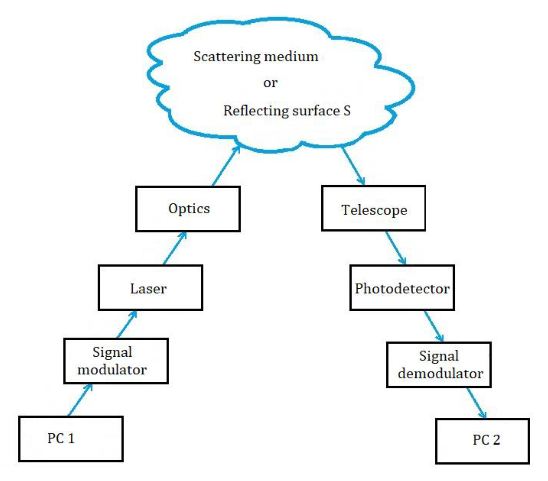
Ld (the distance between the source and the receiver). A block diagram of a typical NLOS communication system is shown in
Figure 1. From our point of view, any NLOS system will have these blocks (
Figure 1), where blocks “Telescope”, “Photodetector”, and “Signal demodulator” are related to the detector of optical waves, and blocks “Signal modulator”, “Laser”, and “Optics” are related to the source of radiation. Characteristics of these blocks comprise a real optical-electronic bistatic system.
We also should note that we do not highlight the ice, because ice has both reflection and scattering properties of optical radiation. These properties are listed in
Figure 1. If we choose to highlight ice, then for atmospheric systems or for experiments underwater during the summer, this drawing will not be suitable and another drawing would be necessary. Under “scattering medium or reflecting surface
S” we define the atmosphere or water region, including that covered by ice, which scatters optical waves by medium or reflects waves from surfaces of flying or moving vehicles, such aircraft. The functions of the units shown in
Figure 1 are as follows. The control computer (PC 1, see
Figure 1) provides information (texts, images, video series, control commands, etc.) to be transmitted through the communication channel. The information modulates laser radiation in the “Signal modulator” unit. After creating the output characteristics in the “Optics” unit, laser radiation is transmitted to the open communication channel. The radiation that has been scattered in the atmosphere or underwater is then focused with a telescope onto the input pupil of a photodetector and is fed to the “Signal demodulator” unit, where received signals are decoded and the retrieved information reaches the computer (PC 2). In the “Optics” unit, the radiation wavelength λ
1 can be converted to λ
2 using, for example, nonlinear crystals. Sometimes, converting the visible range of radiation into UV can be more economical than the purchase of a UV laser with a given pulse repetition rate. The ability exists to modulate and demodulate the radiation in the visible and UV ranges using the same optoelectronic units. We emphasize that the UV radiation used in the experiments was not dangerous for the operators because only scattered radiation is detected, and the laser beam is thus directed into the upper hemisphere relative to the Earth’s surface.
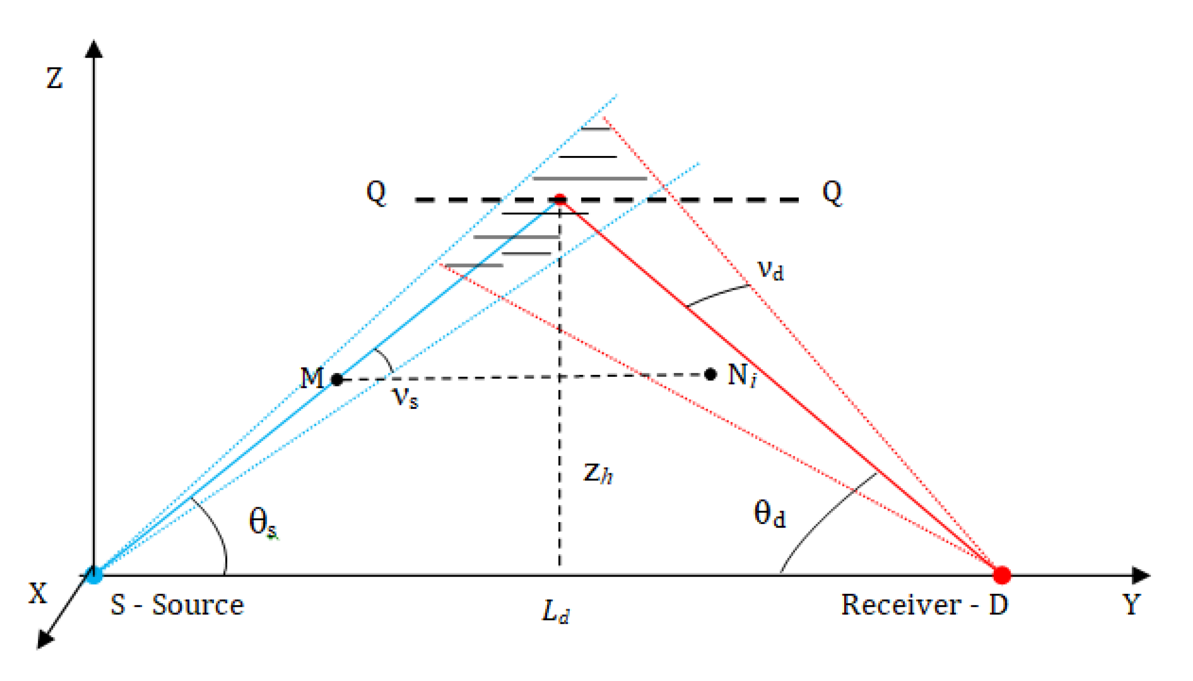
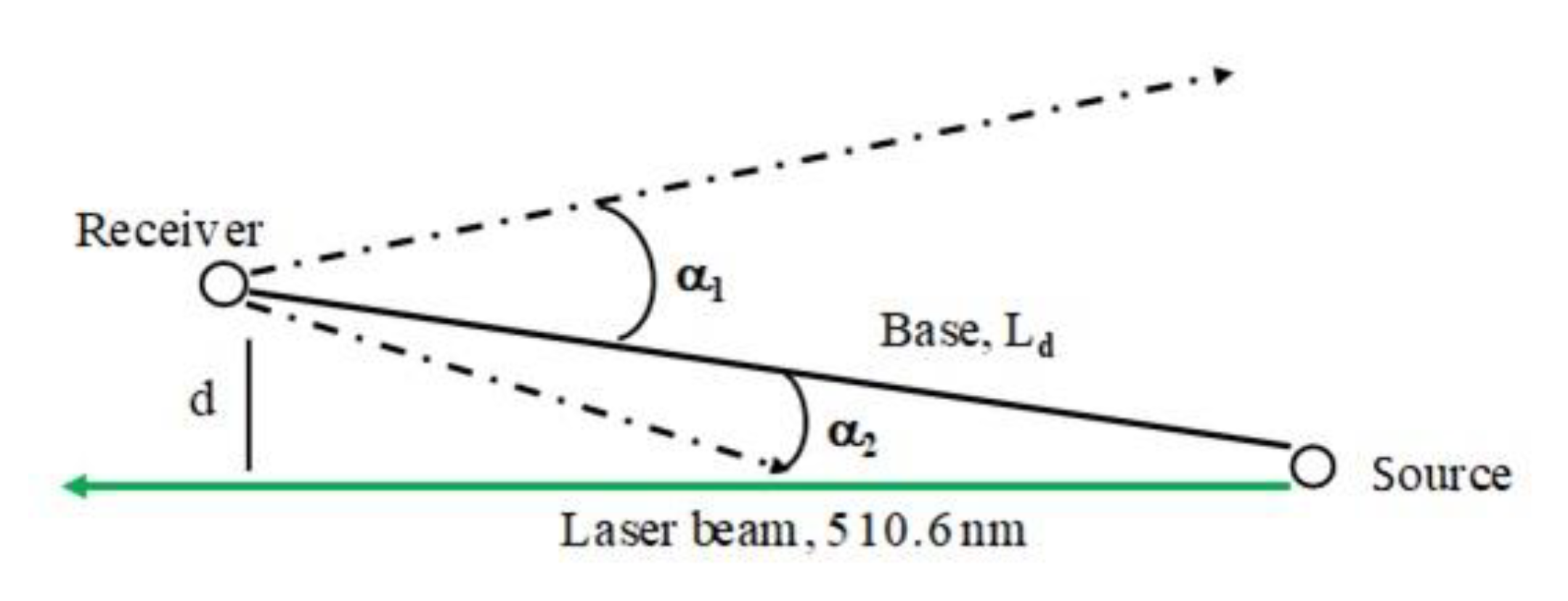
Figure 2 shows a coplanar configuration of a bistatic communication channel.
The main OECS output characteristics are the error probability
p, its standard deviation (SD) σ, and the rate of symbol transfer. Each of these characteristics depends on the above-listed parameters of the transceiving system and on the geometric schemes of the bistatic OECS channels. Therefore, the main objectives of theoretical and experimental investigations of bistatic communication or control systems are the determination of the values of these characteristics, and their dependence on all of the other parameters of a particular OECS and its units, in addition to the optical state of the radiation propagation channels from the source to the receiver (for example, see [
2,
3,
4,
5,
6,
7,
8,
9,
10,
11,
12,
13,
14,
15,
16,
17,
18,
19,
20,
21,
22,
23,
24,
25,
26] and the bibliography therein). In addition, the goal of experimental investigations is to confirm (or refute) theoretical predictions regarding the feasibility of a specific OECS design and its particular characteristics.
3. Theoretical Background
From a system analysis viewpoint, any OECS described by
Figure 1 has two parts: the transceiver (transmitter-receiver) system and the external communication channel. For given optoelectronic units, the output characteristics of the OECS shown in
Figure 2 will depend on the optical state of the radiation propagation channel from the source to the receiver. The state of the atmosphere or water can change between far-apart limits [
27,
28,
29,
30,
31]. Hence, in [
2,
3,
4,
5,
6,
7,
8,
9,
10,
11,
12,
13,
14,
15,
16,
17,
18,
19,
20,
21,
22,
23,
24,
25,
26] much attention was focused on an analysis of the influence of the input OECS parameters and the optical properties of the atmosphere on the communication quality. The optical properties of the communication channel, with all other conditions remaining the same, could limit the maximum transmission range of an OECS and increase the error probability. One way to overcome these difficulties is to apply a controllable decrease in the rate of information transfer. The transfer properties of bistatic OECS channels were investigated in the context of the theory of short-wavelength radiation transfer in scattering and absorbing media (e.g., the atmosphere and water) and the theory of linear system analysis. The radiation transfer equation (RTE) establishes a relationship between the light flux intensity at a given point, and in a preset direction in the medium and its optical characteristics. In the integral-differential form, it can be written as
where
I = I (λ,
r,ω) is the light intensity at a point
r in direction
ω,
c is the velocity of light,
βext(λ,
r) is the extinction coefficient at the point
r,
βsc(λ,
r) is the scattering coefficient at the point
r,
g (λ,
r,ω,
ω’) is the normalized scattering phase function at the point
r in the direction
ω,
ω’ is the direction of radiation propagation before scattering, and Φ
0 is the source function at the point
r in the direction
ω. Equation (1) is linear with light intensity; therefore, it is expedient to analyze the transfer properties of the bistatic communication channel in the context of linear systems theory, that is, to investigate the channel response
h(
t) to the input δ(
t) pulse depending on the input OECS parameters.
Equation (1) has no general analytical solution. To solve it for NLOS communication systems, various algorithms using the Monte Carlo method (from direct simulation algorithms [
18] to algorithms based on modified double local estimates [
9]) are often used. In [
9] we suggested a modified algorithm of the Monte Carlo method with double local estimates from each point of photon collision in the medium with scattering centers at each preset time interval. The procedure of estimation involves the following steps [
9].
A mobile Cartesian coordinate system centered at the receiver point D is constructed at each collision point. The Dy’ axis is directed toward the point of next collision M, the Dz’ axis is perpendicular to the Dy’ axes and lies in the plane containing the source axis and the vertical, and the Dx’ axis is perpendicular to the Dy’ and Dz’ axes and oriented such that the three vectors form a right-handed system of coordinates. A random direction (a, b, c) uniformly distributed over the solid angle is chosen within the field-of-view of the receiving system in the mobile system of coordinates.
In the mobile system of coordinates, sub-regions are constructed within the field-of-view of the receiving system. The boundaries of these sub-regions are formed by the field-of-view cones and ellipsoids of rotation. The equations of the ellipsoids of rotations are defined by the focal parameters
Pi and eccentricities
ei. The corresponding expressions were presented in [
9]. For each sub-region thus obtained, its own intermediate collision point
Ni is constructed on the beam formed by the direction (
a,
b,
c). For each intermediate collision point
Ni, the double local estimate of the radiation intensity is constructed after scattering at point
M and arrival at point
Ni, and then further scattered at this point and arriving at the receiving system
D. The estimate is calculated from the formula:
where ω is the photon “weight” at the collision point
M, σ
s is the scattering coefficient, σ
t is the extinction coefficient,
g is the scattering phase function,
is the radius vector of the collision point
M,
is the radius-vector of the intermediate point of collision
Ni,
is the angle of scattering measured from the direction of the photon trajectory before the collision to the
MNi direction,
is the angle of scattering from the direction
MNi to the direction
NiD,
b is the second coordinate of the random direction (
a,
b,
c) in the mobile system of coordinates,
is the optical thickness from the collision point
M to the intermediate collision point
Ni, and
is the optical thickness from the intermediate collision point to the receiving system. In [
9] the unbiased nature of the estimates obtained using this algorithm was proven. It was also shown that this algorithm is much less energy-consuming than the conventional algorithm of the double local estimate.
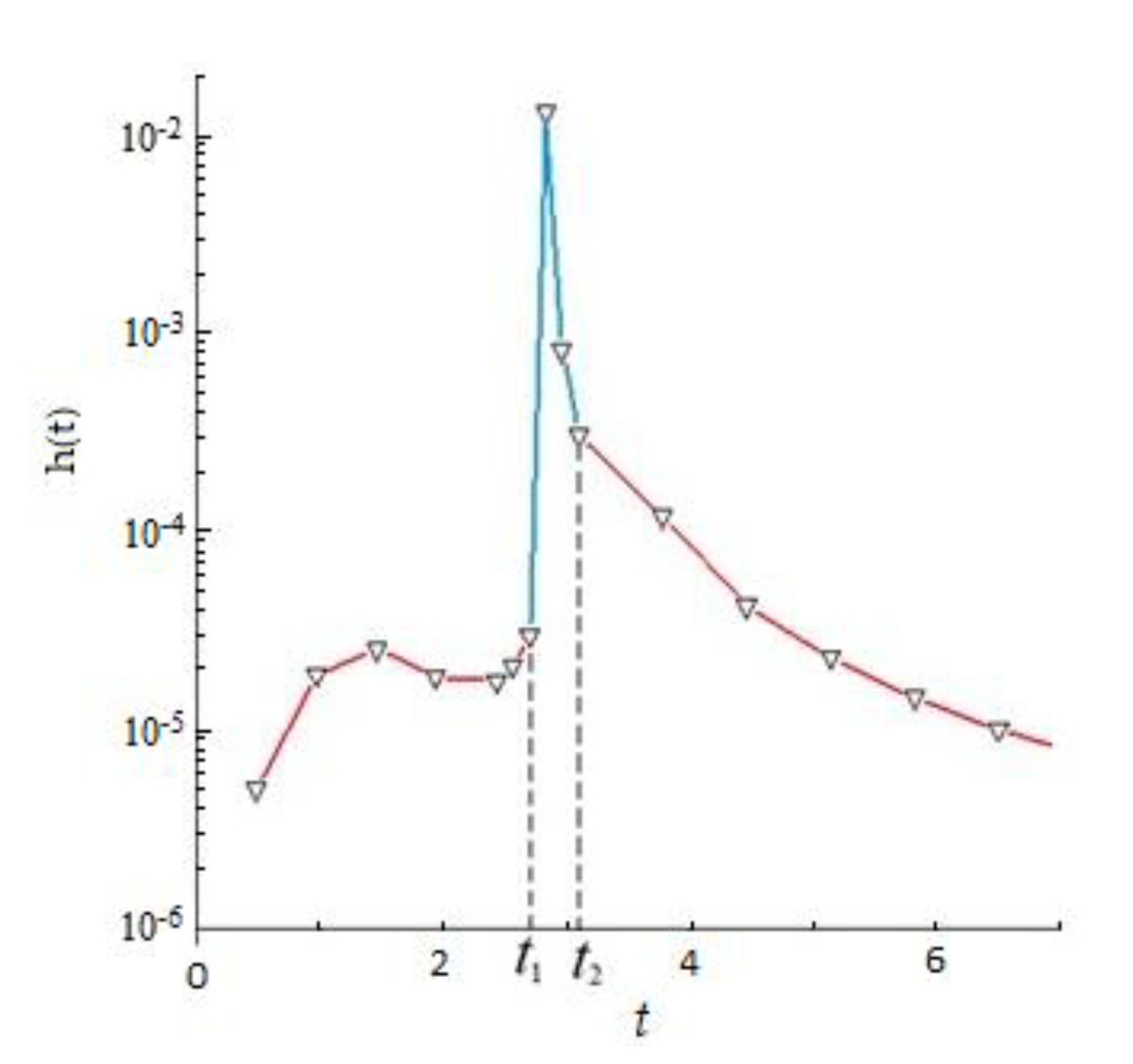
Clearly, the single-scattering approximation for estimating the impulse response characteristic
h(
t), pulse broadening, etc., has limitations. This follows from the analysis of the impulse responses of NLOS communication channels, whose typical form is shown in
Figure 3. The time interval [
t1,
t2] shown in
Figure 3 indicates the period of intersection of the laser beam divergence angle with the field-of-view angle of the receiving system (forming the hatched area shown in
Figure 2). The function
h(
t) for
t beyond this interval is determined by radiation that has been multiply scattered, that is, the leading and trailing fronts of the impulse response
h(
t) shown in
Figure 3 can be determined by solving the RTE (1) allowing for multiple scattering of no less than the second order. For atmospheric OECS, it is possible to choose the spectral characteristics of laser sources over a wide range of the spectrum, from UV to IR. In water, this choice is limited to the visible (green or dark blue) range of the spectrum because of the strong absorption by water of non-visible radiation (for example, see [
12,
26]).
There are a number of drawbacks of the bistatic communication configuration that could result in its unfeasibility. Clearly, for successful communication, the power of the received information-bearing signal must exceed the intrinsic photodetector noise power
Pf. Communication errors arise when this condition is occasionally violated. This can be caused by turbulence in the optical characteristics of the communication channel or by local clots of optically dense scattering or absorbing formations (fragments of smoke plumes, cloudy media, etc.) intersecting the receiver field-of-view. Communication may be unfeasible even when the information-bearing signal power exceeds the noise power. This may be observed when values of the impulse response at
t <
t1 and
t → t1 or at
t >
t2 and
t → t2 become close or equal to max
h(
t) in the central part (see
Figure 3). Proceeding from these general considerations of the optical radiation’s interaction with scattering and absorbing media, we now consider the influence of some optical and geometric parameters of bistatic OECS on the communication range and error probability. Consider the following: fix all geometric and optical parameters and all photodetector characteristics; let the divergence angle ν
s of the laser radiation beam be zero and the communication range be
Ld. It is clear from
Figure 2 that the maximum reasonable value is vs. = θ
s rather than π/2. To obtain the
Ld dependence on ν
s we increase it from zero to θ
s and examine the effect on the impulse response (
Figure 3). The duration of its leading edge will decrease, that is, the interval [0,
t1]
→ 0. The interval [
t1,
t2] will monotonically increase, and the maximum value of the impulse response will decrease, thereby increasing the error probabilities and decreasing the maximum base distances
Ld.
Now, we let all optical and geometric parameters of the OECS scheme (
Figure 2) be fixed except for the field-of-view angle ν
d of the receiving optical system that will monotonically increase from zero. Assume that at ν
d = 0 the communication range of the OECS is equal to
Ld. It can be easily demonstrated that as ν
d, increases, the power at the leading edge of the impulse response
h(
t) will increase, together with the time interval [
t1,
t2] (
Figure 3), but the maximal
h(
t) will not increase. Both of these factors increase the communication errors, that is, from a certain critical ν
d value, the base
Ld will decrease. It is straightforward to predict the dependence of
Ld on some optical properties of the medium forming the OECS channel shown in
Figure 2. Let the optical characteristics of the medium be homogeneous. Fix values of all other OECS parameters and let the medium be non-scattering. Obviously, when the base
Ld = 0, the error probability
p = 0, and the rate of symbol transfer
s = 0. Now, let the scattering coefficient
βsc → ∞; then, obviously, as
Ld → 0, the error probability
p → 0, and the rate of symbol transfer
s → 0. Hence, for each
βsc value there exists nonzero values of
Ld,
p, and
s. This implies that for each set of input OECS parameters, there exists an optical state of the medium at which a maximal base distance
Ld can be observed. This suggests that the optimal communication conditions (at least, from the viewpoint of the level of max
h(
t)) pertaining to variations in the orientation angles of the transmitted, θ
s, and receiving, θ
d, axes (given that all other OECS parameters remain the same) are realized when θ
s and θ
d → 0°. It is obvious that an increase in the average or peak laser radiation power will lead to an increase in the maximal
Ld value.
In [
7,
9,
20] results of statistical simulation of the impulse responses of the atmospheric and underwater communication channels using the Monte Carlo method, for various external and internal characteristics and parameters of the communication channels obtained in Russia at the Institute of Atmospheric Optics of the SB RAS (IAO SB RAS), were analyzed. A series of numerical experiments, discussed in [
9], were performed with the LOWTRAN-7 optical aerosol-gas models of the atmosphere and the meteorological visibility ranges
SM = 10 and 50 km; wavelengths λ = 0.3, 0.5, and 0.9 μm; angles θ
s = θ
d = 5°; ν
s = 0.0034°;
= 2°; and
Ld = 0.5–200 km. In calculations, 30 packages, comprising 10
8 photon histories each, were simulated, and provided errors of estimating the response
h(
t) not exceeding 0.15–10%. The main conclusions from the analysis of the transfer properties of the atmospheric communication channels performed in [
9] are the following. For short base distances (2–3 km), with other conditions remaining unchanged, the received information-bearing pulse power was maximal at the radiation wavelength λ = 0.3 μm. For longer base distances and low turbidity of the media (meteorological visibility range
SM ≥ 50 km), maximal power was reached at λ = 0.5 μm. For high atmospheric turbidity (
SM ≤ 10 km), the maximal ranges were observed at λ = 0.5 μm and λ = 0.9 μm, depending on the orientation of the receiving plane. It was demonstrated that the maximal pulse transmission frequencies for bistatic optoelectronic communication systems were between 4 × 10
3 and 2 × 10
7 Hz, depending on the optical conditions in the atmosphere and geometric parameters of the communication channels.
In [
20], in which underwater NLOS was studied, it was demonstrated that for communication at the wavelength λ = 0.5 μm and visibility depth
zw = 30 m for ranges 10–100 m and a wide variety of orientations of the source and receiver optical axes, the lower limit of radiation power recorded at the receiver must differ from the power of the radiation source by η ≥ 150 dB. In this case, the maximum number of transmitted pulses
was between 3 × 10
6 Hz and 2 × 10
7 Hz for a source pulse duration of Δ
t = 30 ns. The transfer properties of underwater optical communication channels with scattered laser radiation were simulated for optical water characteristics taken from [
29,
31]. These simple discussions allow us to evaluate and estimate the coincidence between the obtained theoretical and experimental results. Here we want to note that during the above theoretical analysis, we did not account for the influence of atmospheric characteristics or water medium, or the characteristics of the detector or source on the probability of error in communication, because in
Section 4, we proposed and realized techniques to control it at a real-time scale.
5. Conclusions
In recent decades, comprehensive theoretical and experimental investigations of optical communication systems based on scattered laser radiation have been carried out in atmospheric and water media in Russia. Results of these investigations have been published in [
7,
9,
13,
14,
19,
20,
34]. Theoretical research has been carried out using the Monte Carlo method. For this purpose, a new modification of the algorithm of double local estimate has been developed for the purpose of simulation of the impulse response of external (atmospheric or water) channels with optical radiation scattering and absorption [
7]. Simulations have been carried out in a wide range of optical-geometric conditions of observations, and employing coplanar NLOS communication schemes [
9]. Atmospheric NLOS communication systems with radiation sources in the visible, near-IR, and UV wavelength ranges (λ = 300, 500, and 900 nm) for meteorological visibility between 10 and 50 km have been investigated. Underwater NLOS communication systems have been considered for radiation sources at a wavelength of 300 nm and visibility depth of 30 m for a wide range of orientation angles of the source and receiver optical axes [
20].
A new effective version of the Monte Carlo double local estimation algorithm has been created for the statistical simulation of the impulse response characteristics of coplanar atmospheric and underwater NLOS channels taking into account multiple scattering and absorption of optical radiation in dispersed media. Monte Carlo simulations have been used to estimate the maximum transmission ranges and the pulse transfer characteristics for these hypothetical communication systems, taking into account the parameters of photoelectron multipliers [
9,
20]. In particular, for atmospheric communication systems, the conditions under which these ranges can reach more than 100 km with a pulse transfer rate of 2 × 10
7 Hz have been determined. Underwater NLOS communication was realized for base distances around 10–100 m and pulse transfer rates from 3 × 10
6 Hz to 2 × 10
7 Hz. Based on numerical experiments, for the first time, the limiting ranges of action and transmission rates of pulses in bistatic communication systems were established for radiation sources at wavelengths of 300, 500, and 900 nm for given angles of divergence of radiation, field of view of receivers, and meteorological ranges of visibility in the atmosphere. Scanning the corresponding global literature regarding similar investigations allows us to emphasize that there are no analogues in studies of competing scientific groups.
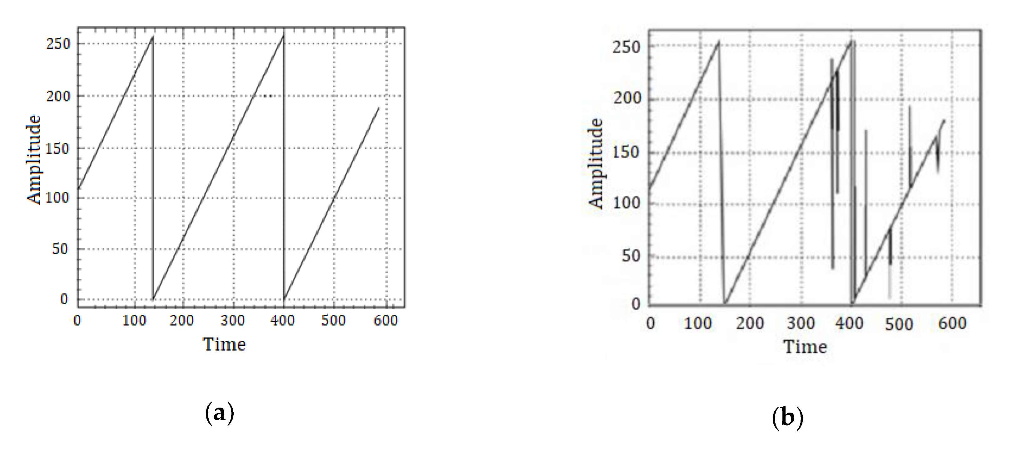
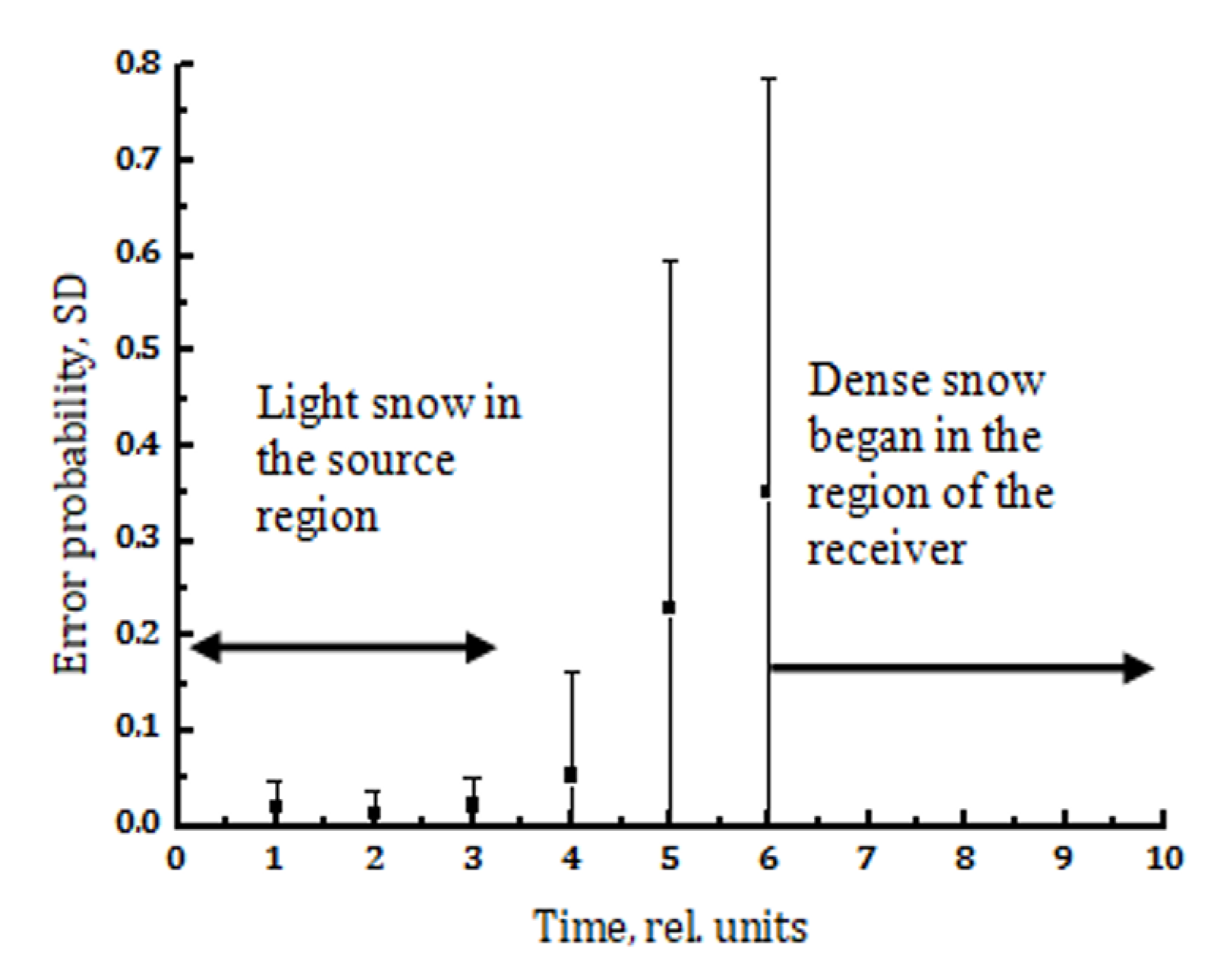
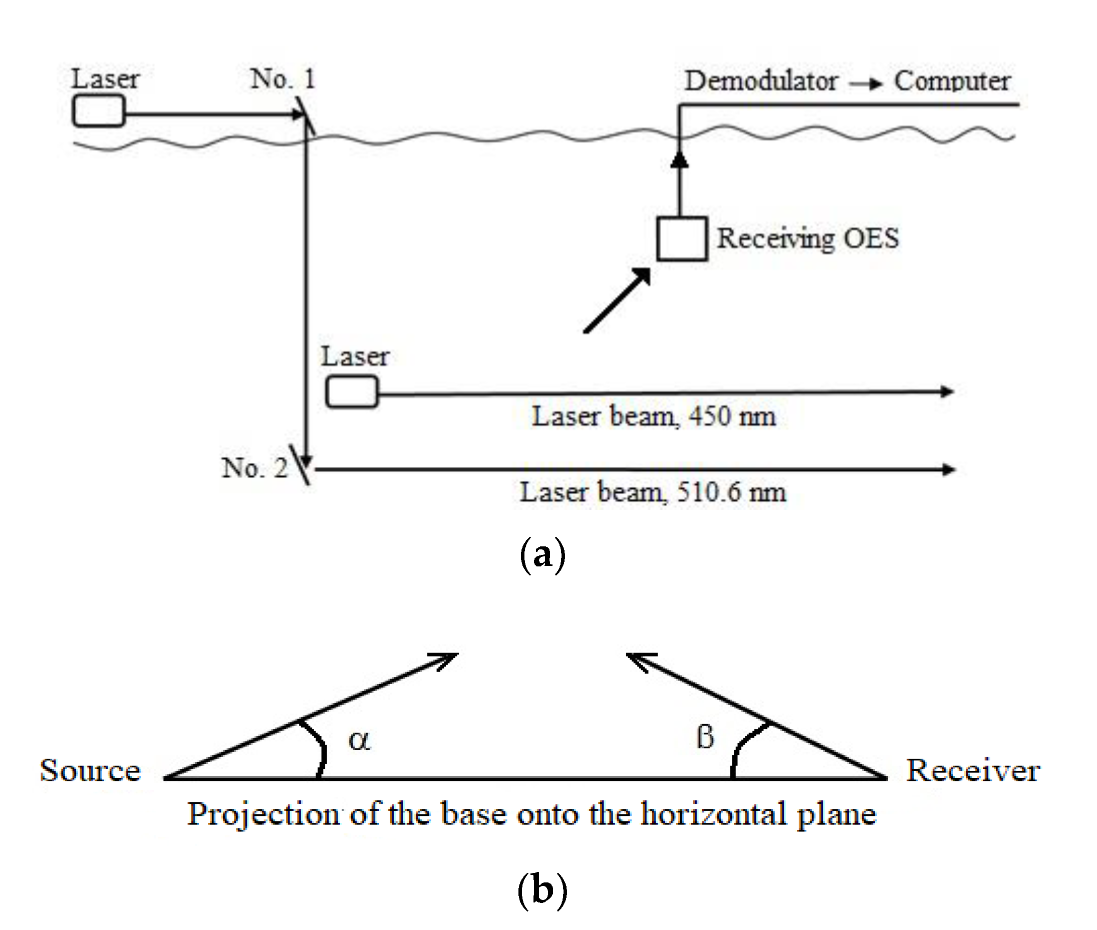
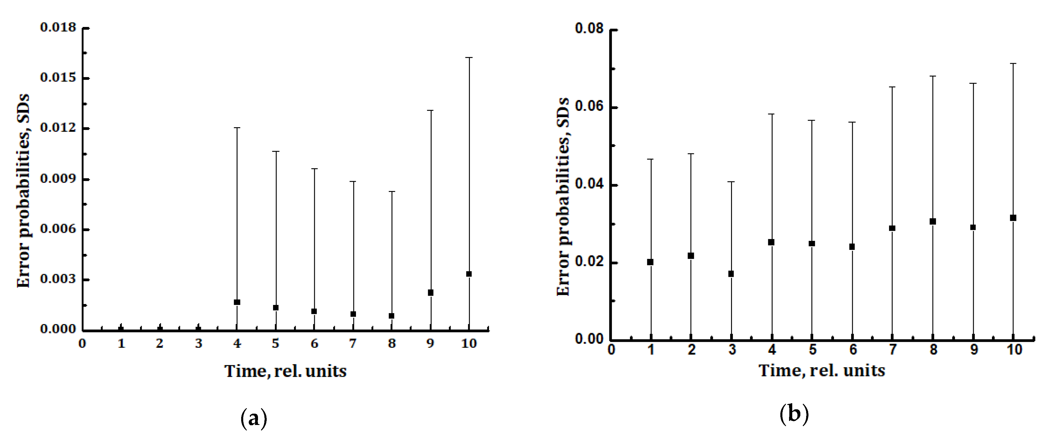
Experimental investigations of atmospheric and underwater NLOS communication systems were performed outdoors in Russia. No laboratory experiments were carried out for these purposes. For the first time, a method for estimating the probabilities of communication errors and their standard deviations in real time has been proposed and implemented. It can be used to diagnose the quality of NLOS communication channels and select the characteristics of the transmitter–receiver units to ensure their maximum quality. To evaluate the performance of NLOS communication in real time, a simple technique of estimating the communication error probabilities and SD was used in the experiments.
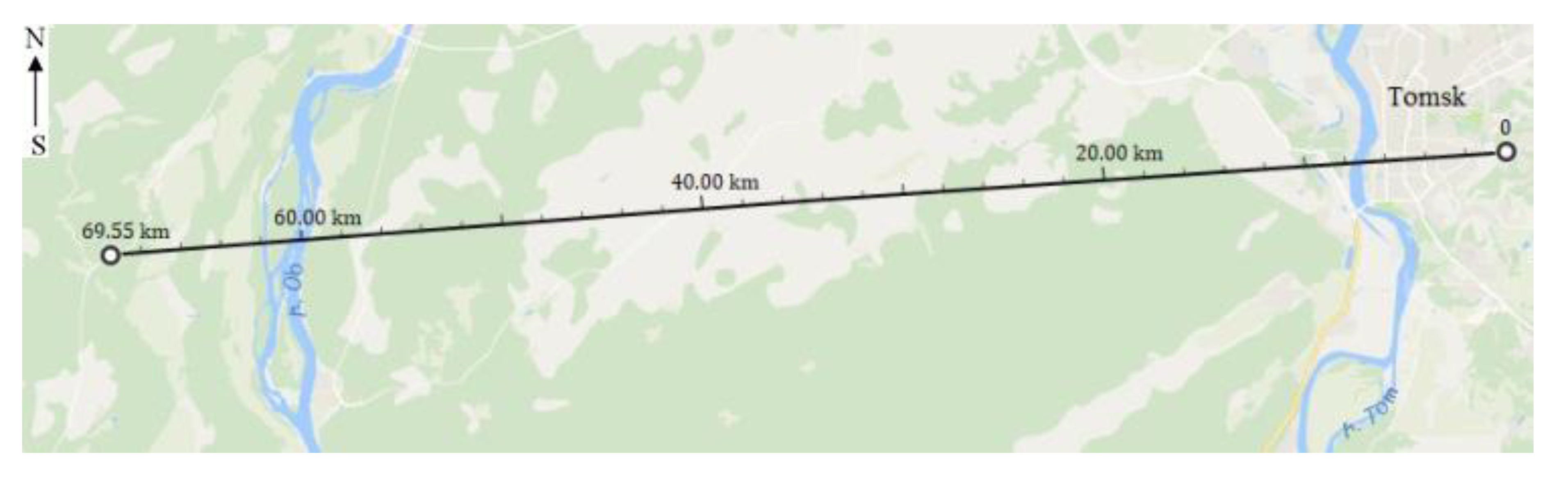
NLOS communication was realized for base distances up to 70 km in the visible range at a wavelength of 510.6 nm at night, and up to 1.3 km in the UV range at a wavelength of 255.3 nm in the daytime and at night. The experiments were performed under different meteorological conditions in the atmosphere, which varied during the experiments. Underwater NLOS communication was carried out in a freshwater lake (including under ice) at radiation wavelengths of 510.6 and 450 nm at basic distances of up to 40 m. In the forefront of the experimental investigations carried out in Russia stand the underwater NLOS communication trials, including communication under ice. This communication was realized with sources in the visible range, at wavelengths of 510.6 and 450 nm and at distances up to 40 m. We emphasize no data exist in the literature on NLOS experiments of other scientific groups carried out under ice.
In our future research, we plan to conduct NLOS experiments in the IR range at a wavelength of 1064 nm together with our co-authors, commencing in the middle of 2021.


 and
and 


