
Fatigue Behaviour of CFRP Strengthened Out-of-Plane Gusset Welded Joints with Double Cracks

Abstract
:
1. Introduction
2. Experimental Program
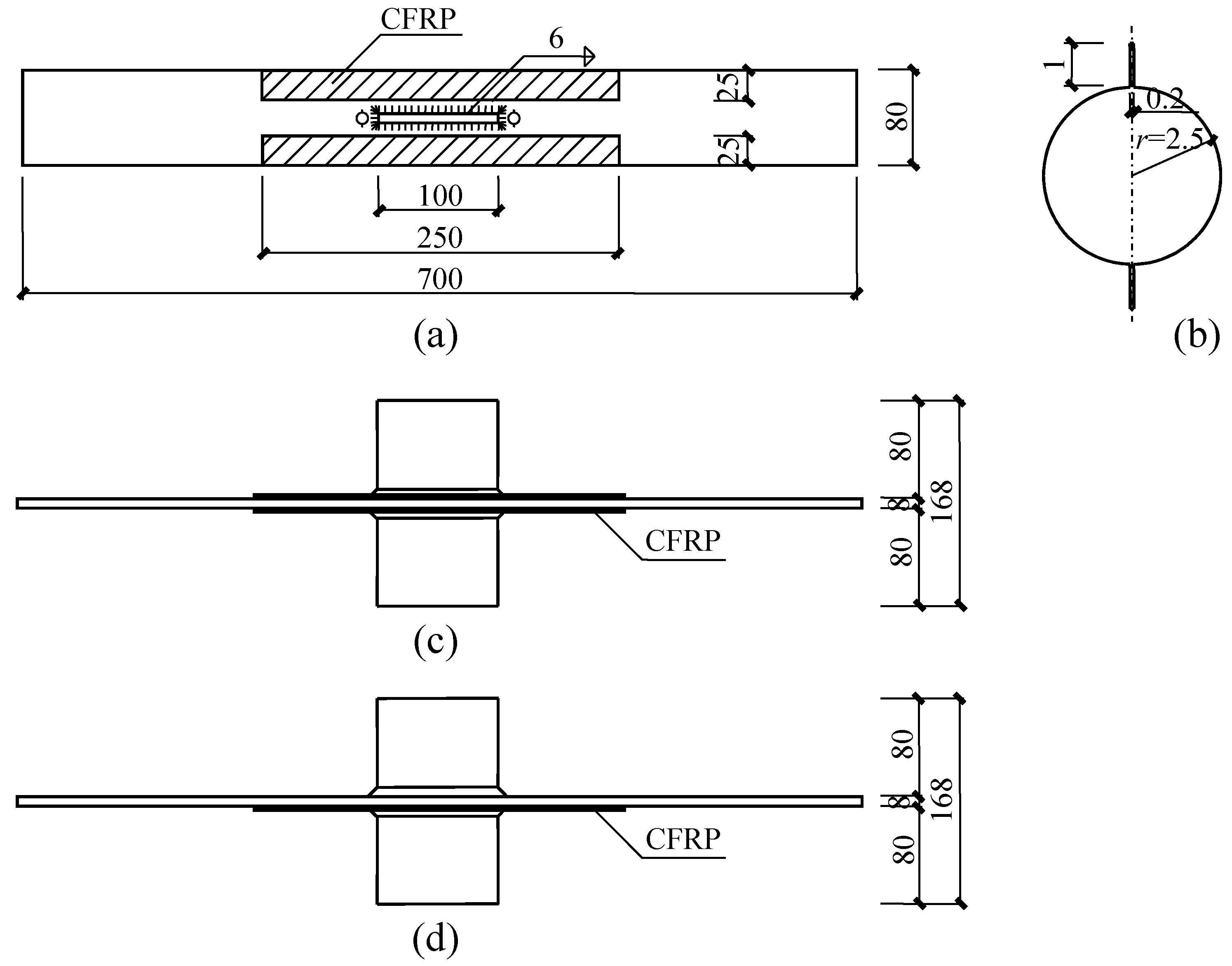
2.1. Configuration of Test Specimens

2.2. Material Properties
2.3. Specimen Preparation
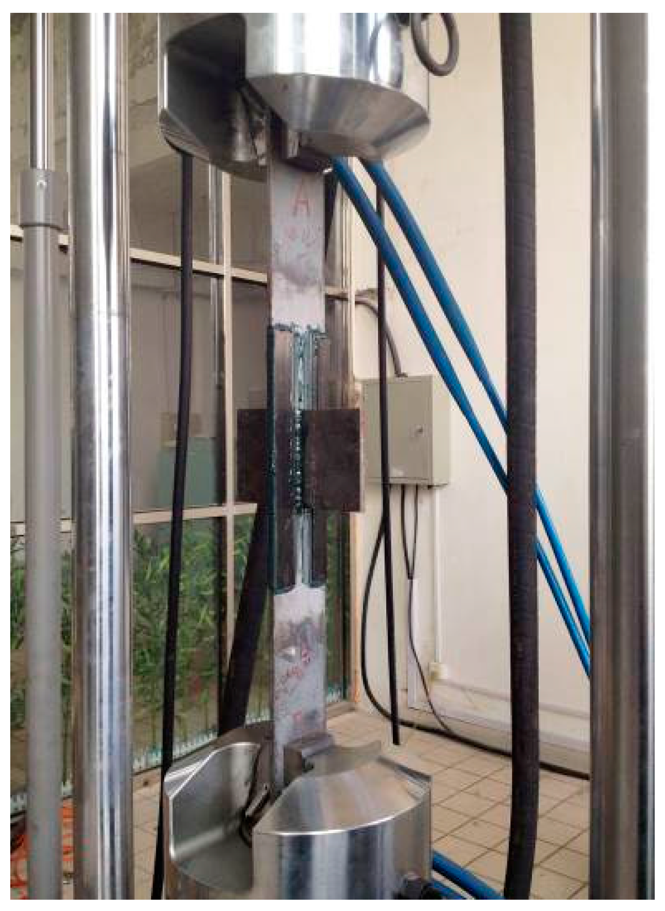
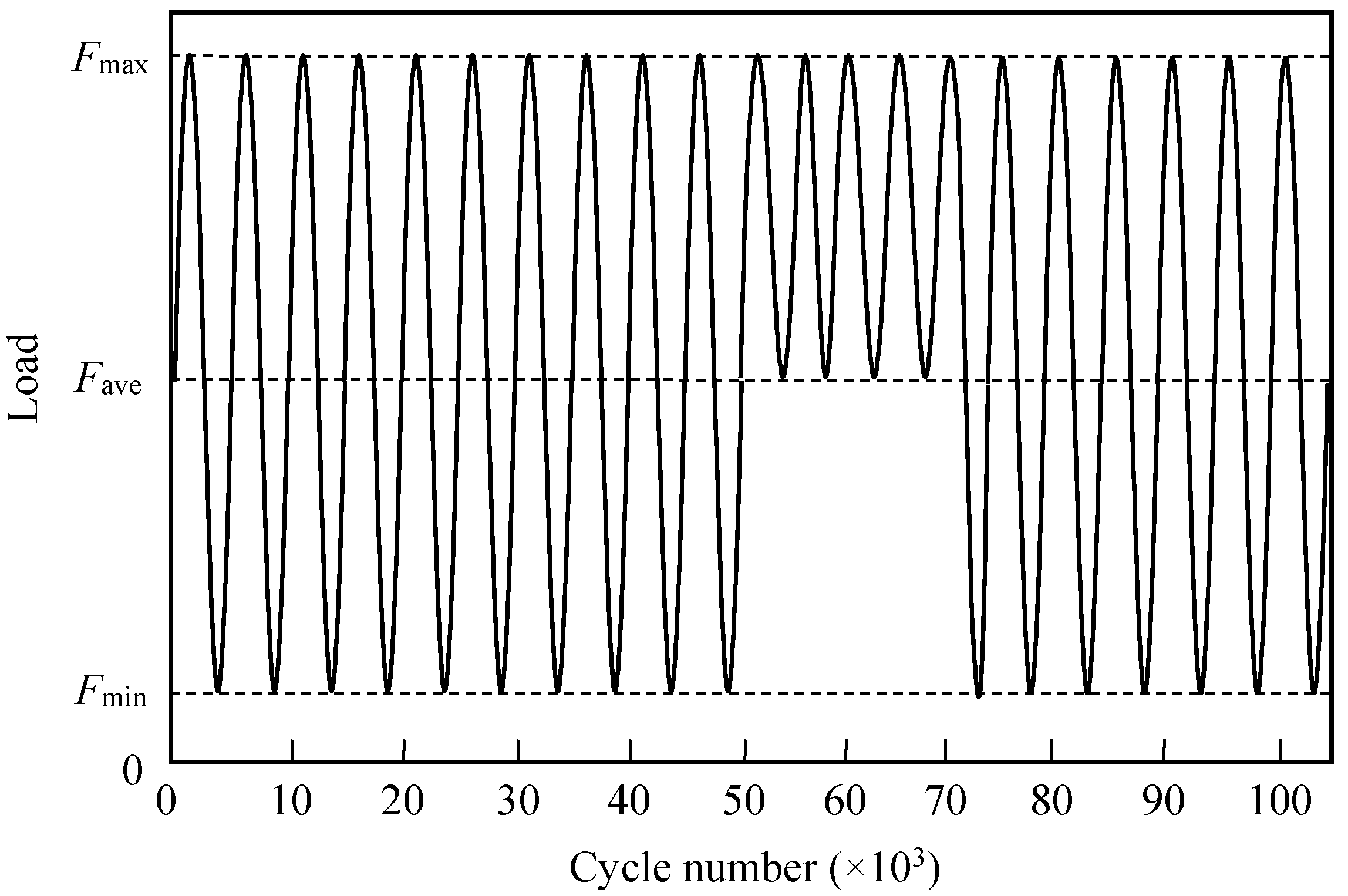
2.4. Fatigue Loading


3. Experimental Results

| Specimen | CFRP modulus | Bond configuration | Stress range (MPa) | Bond thickness (mm) | Tested fatigue cycles (N) | Extension ratio | Predicted fatigue cycles (Np) | Np/N |
|---|---|---|---|---|---|---|---|---|
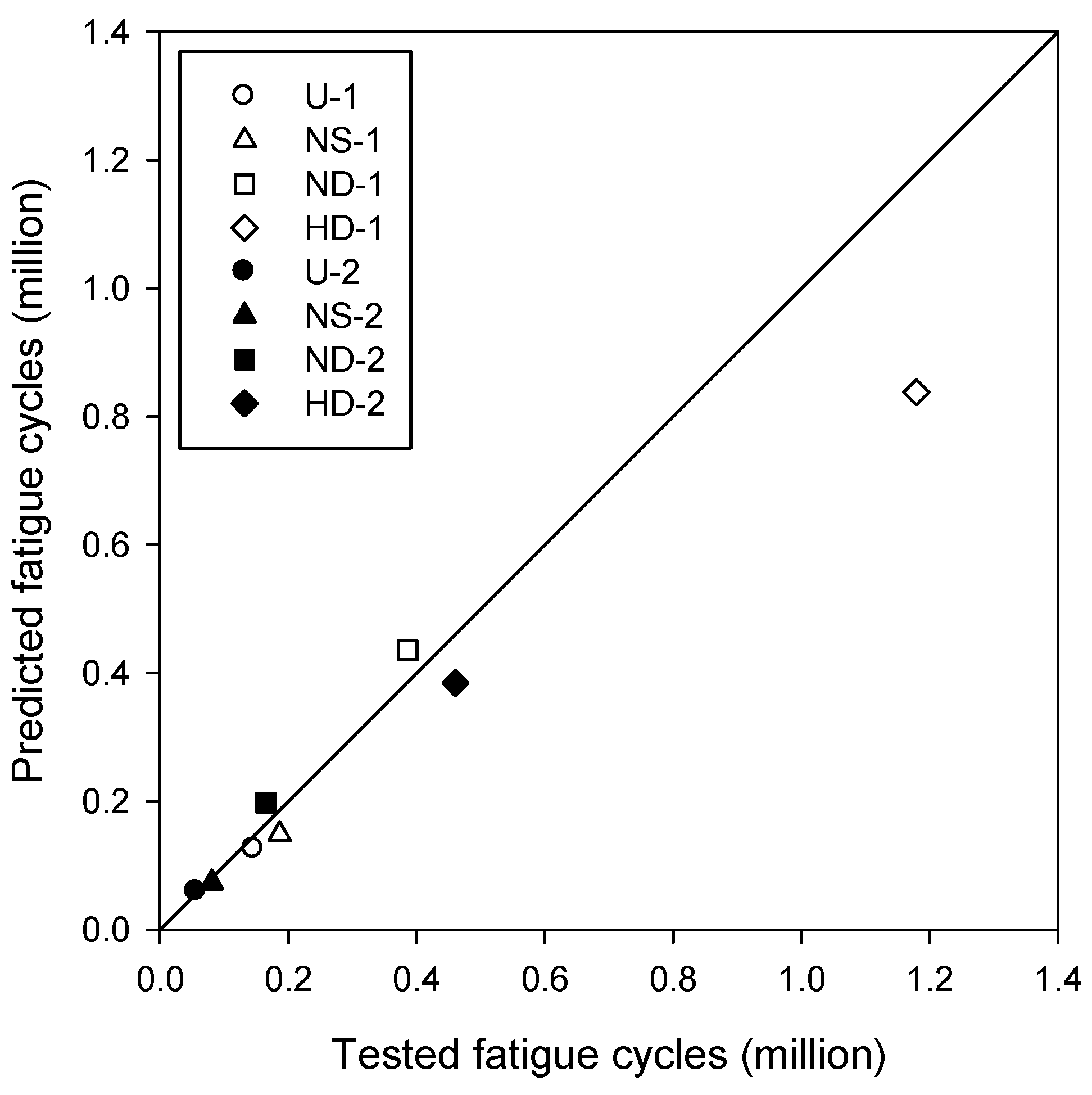
| U-1 | - | - | 120 | - | 146001 | 1.00 | 125720 | 0.86 |
| NS-1 | Normal | Single side | 120 | 0.60 | 186884 | 1.28 | 148590 | 0.80 |
| ND-1 | Normal | Double sides | 120 | 0.43 | 386525 | 2.65 | 435620 | 1.13 |
| HD-1 | Ultra-high | Double sides | 120 | 0.58 | 1179410 | 8.08 | 837750 | 0.71 |
| U-2 | - | - | 153 | - | 56394 | 1.00 | 59653 | 1.05 |
| NS-2 | Normal | Single side | 153 | 0.49 | 80938 | 1.44 | 73131 | 0.90 |
| ND-2 | Normal | Double sides | 153 | 0.42 | 164865 | 2.92 | 198060 | 1.20 |
| HD-2 | Ultra-high | Double sides | 153 | 0.52 | 460952 | 8.17 | 384290 | 0.83 |
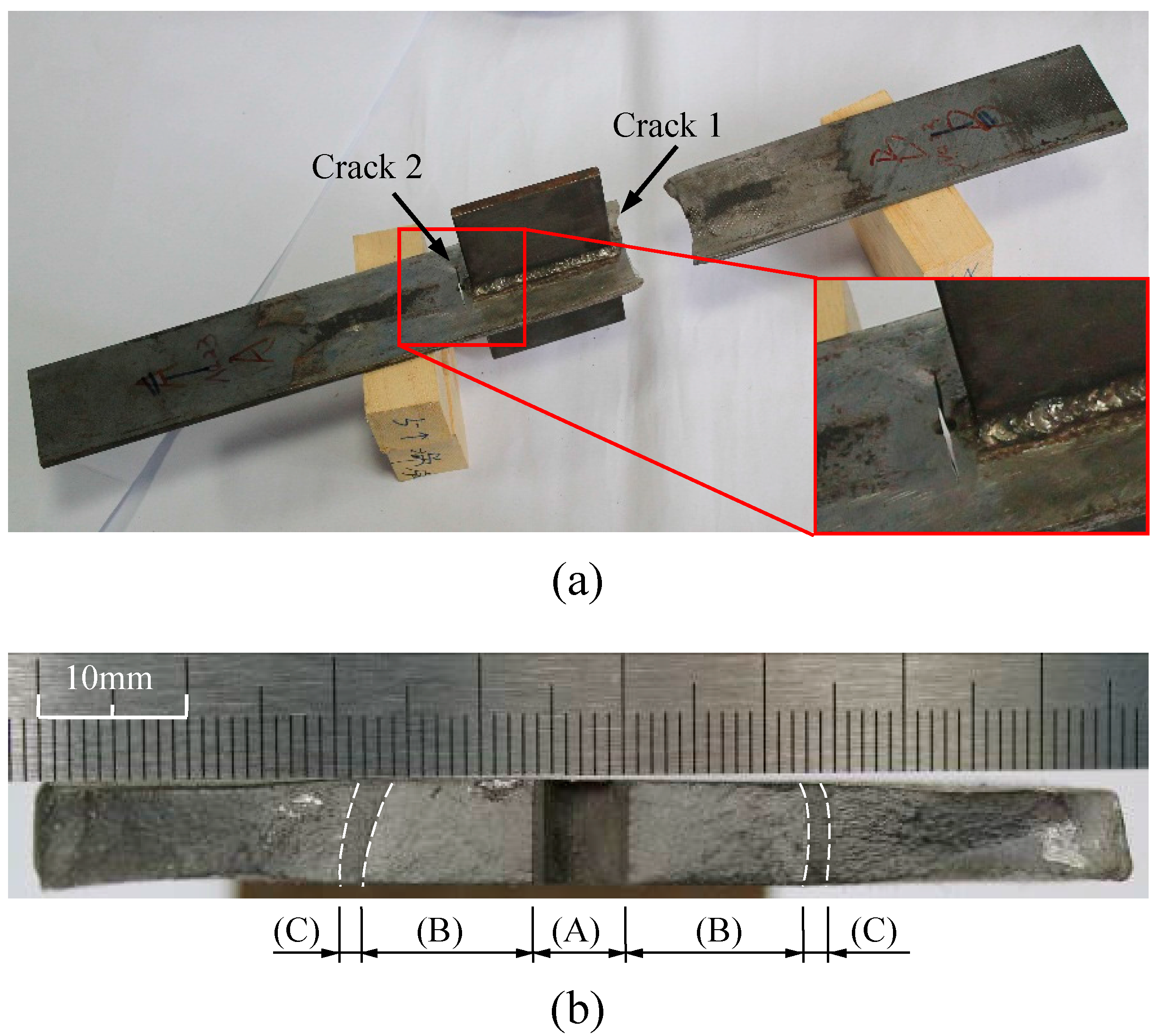
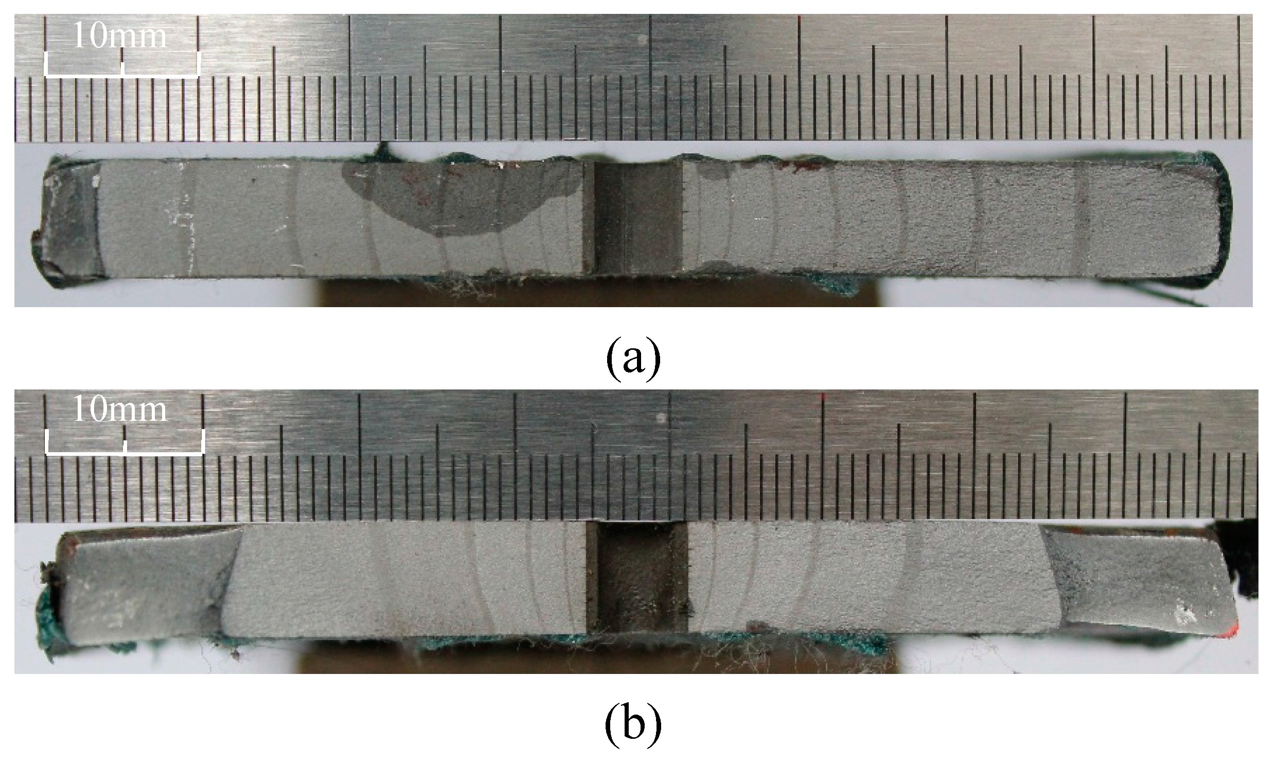
3.1. Failure Mode
3.1.1. Specimen without CFRP Retrofitting

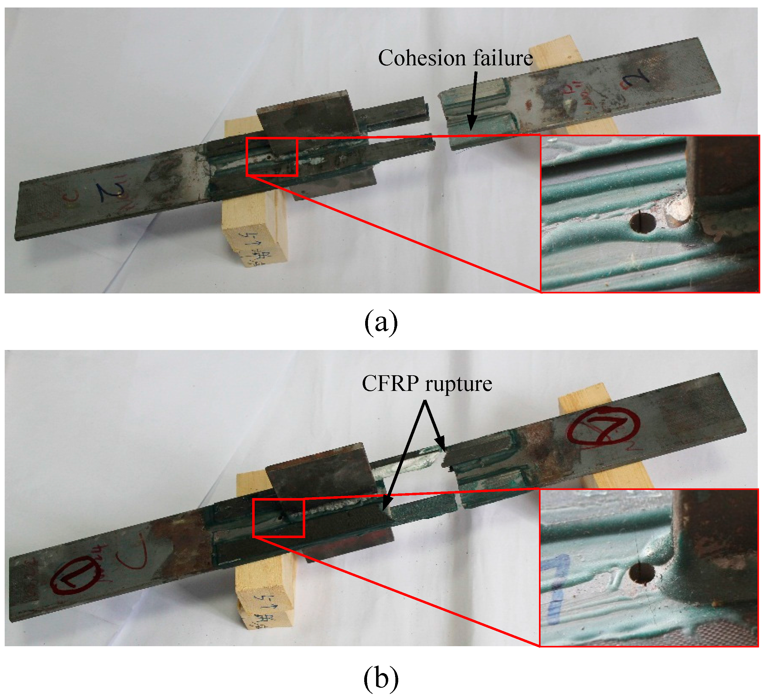
3.1.2. Specimen with CFRP Retrofitting


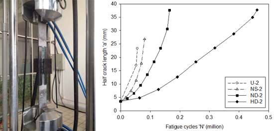
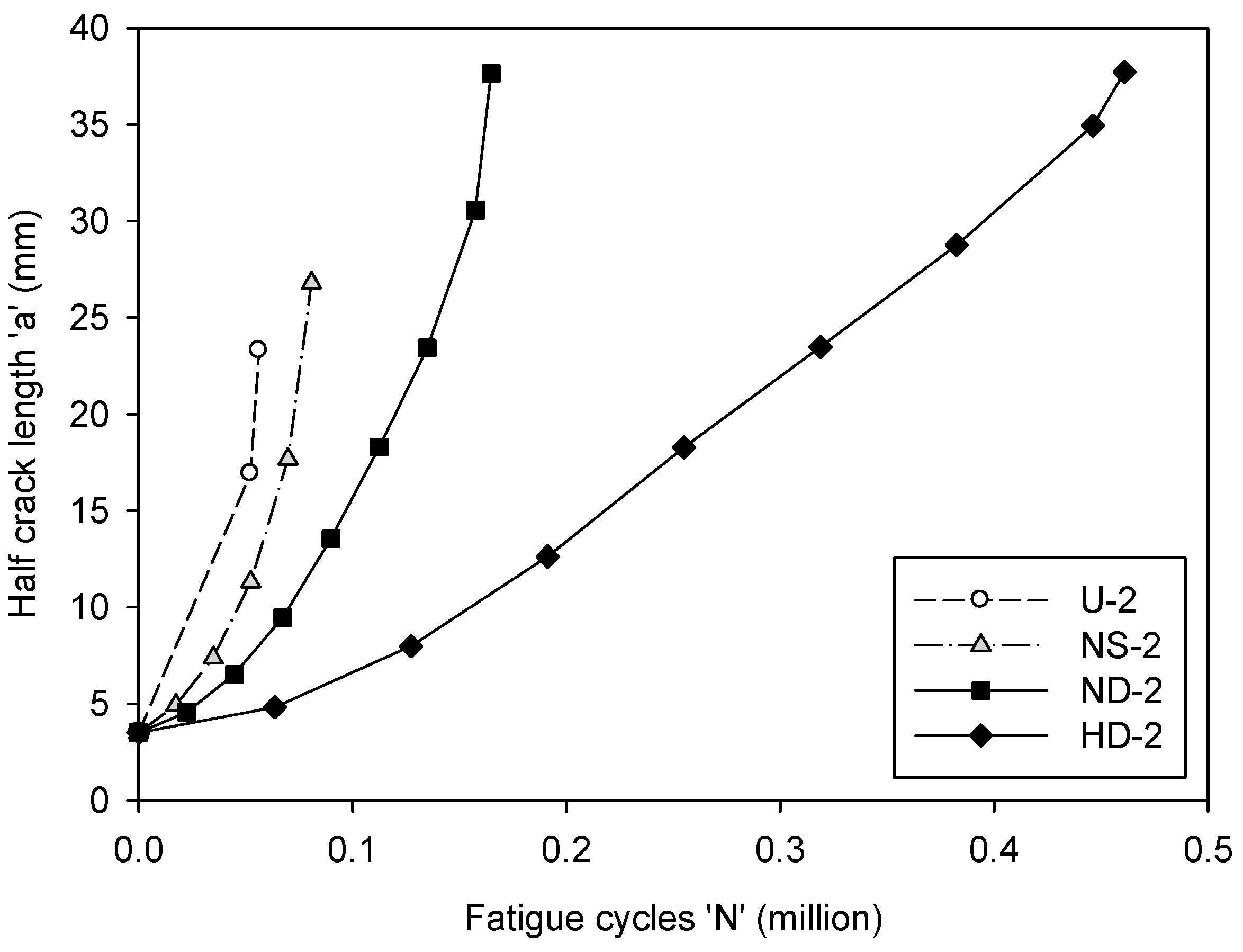
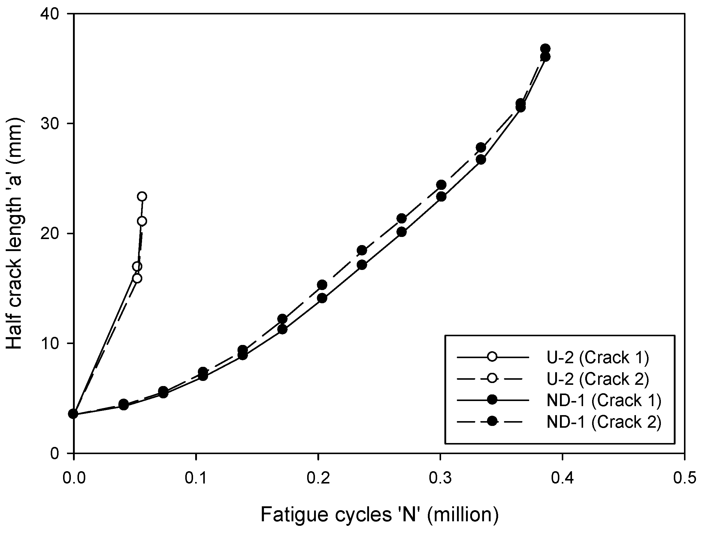
3.2. Fatigue Crack Propagation

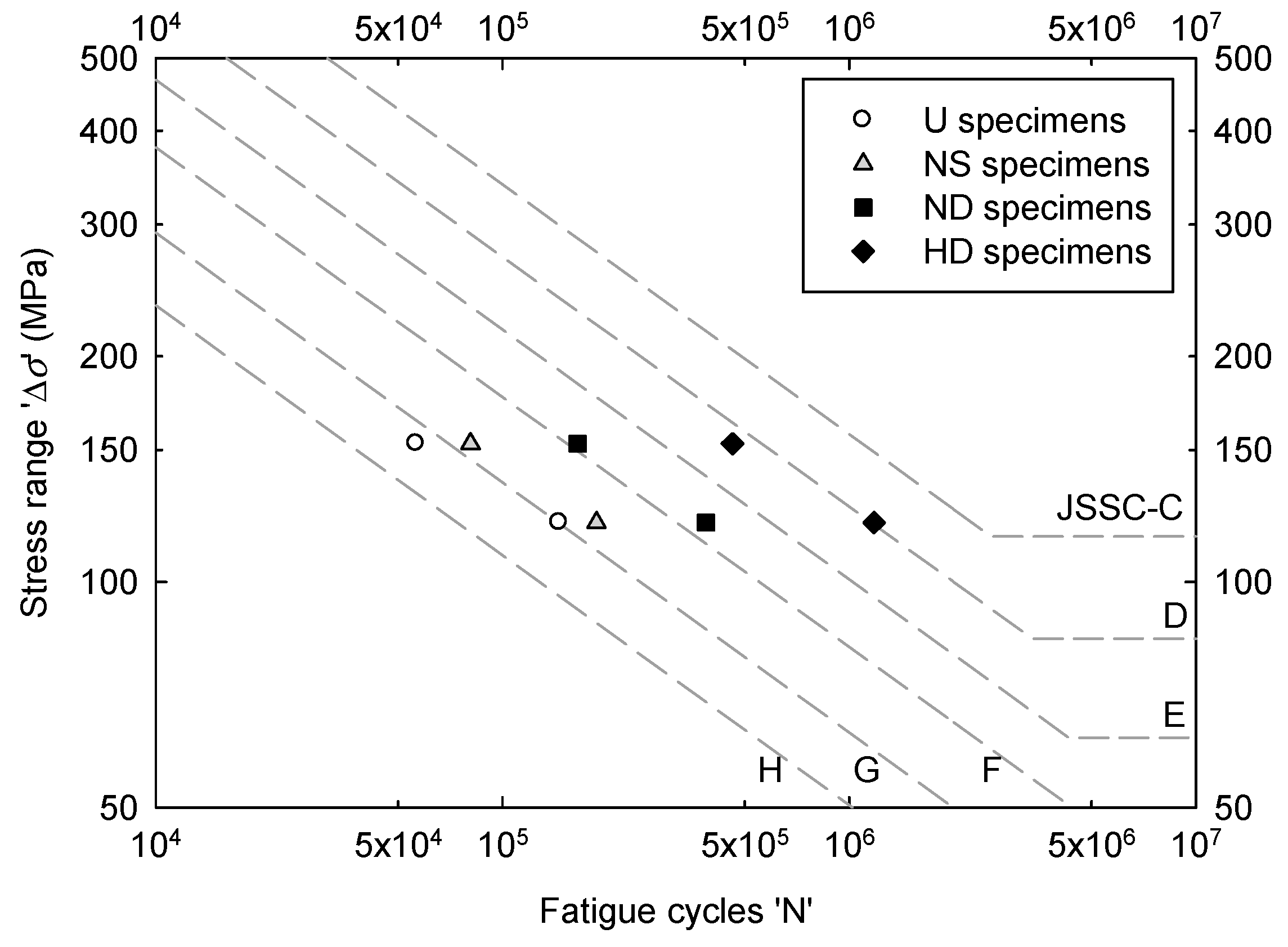
3.3. Fatigue Life


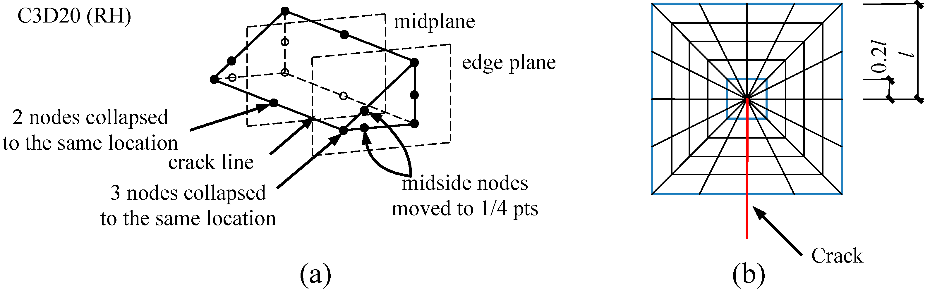
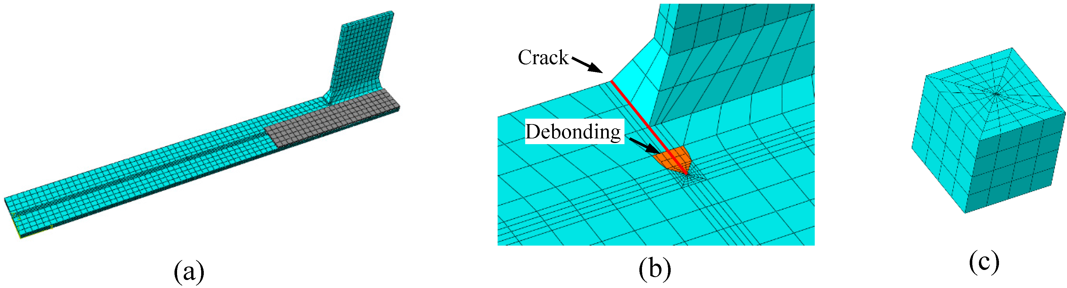
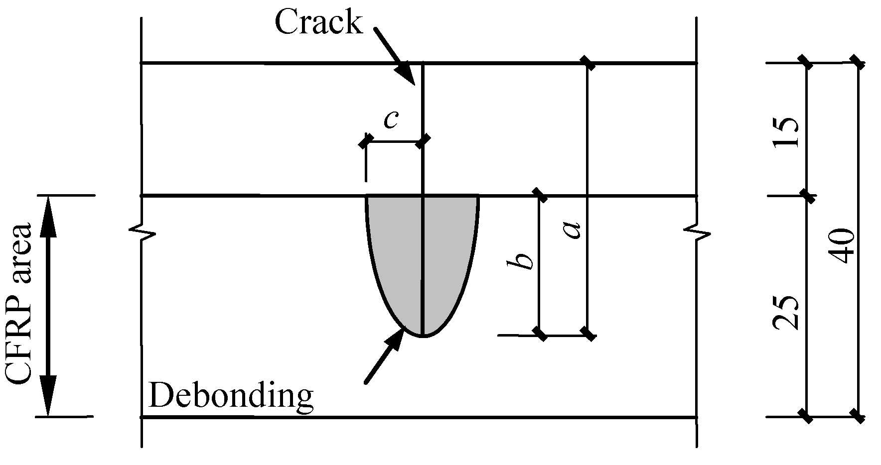
4. Finite Element Modelling


5. Numerical Results
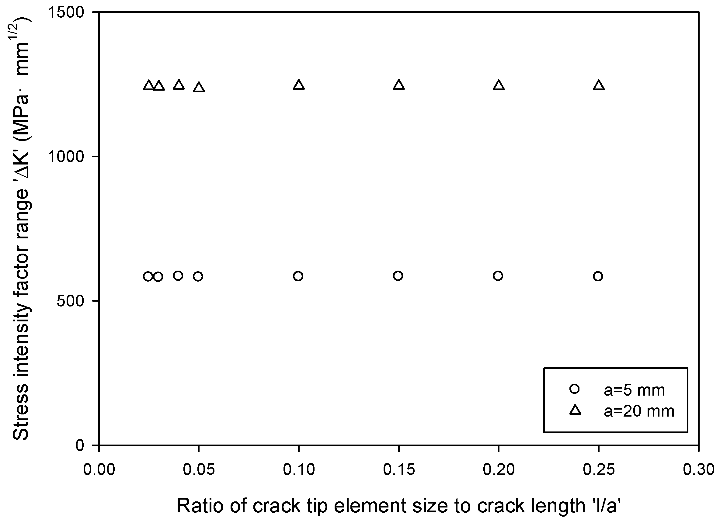
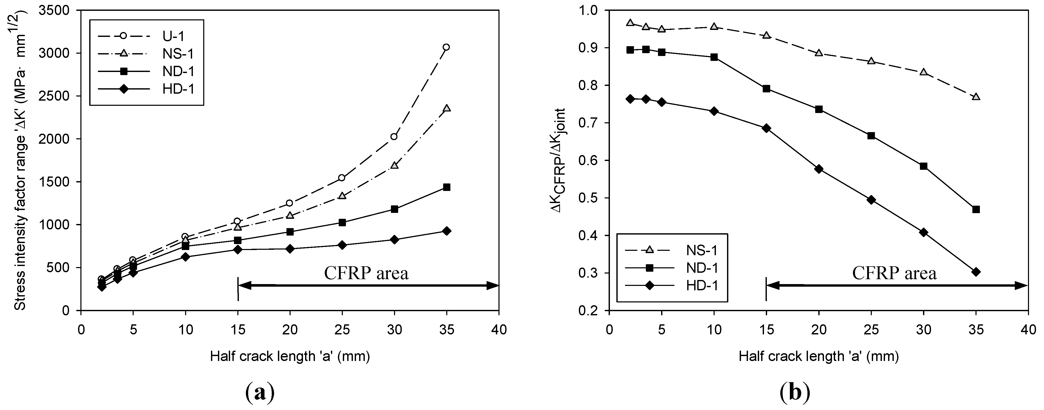
5.1. Stress Intensity Factor

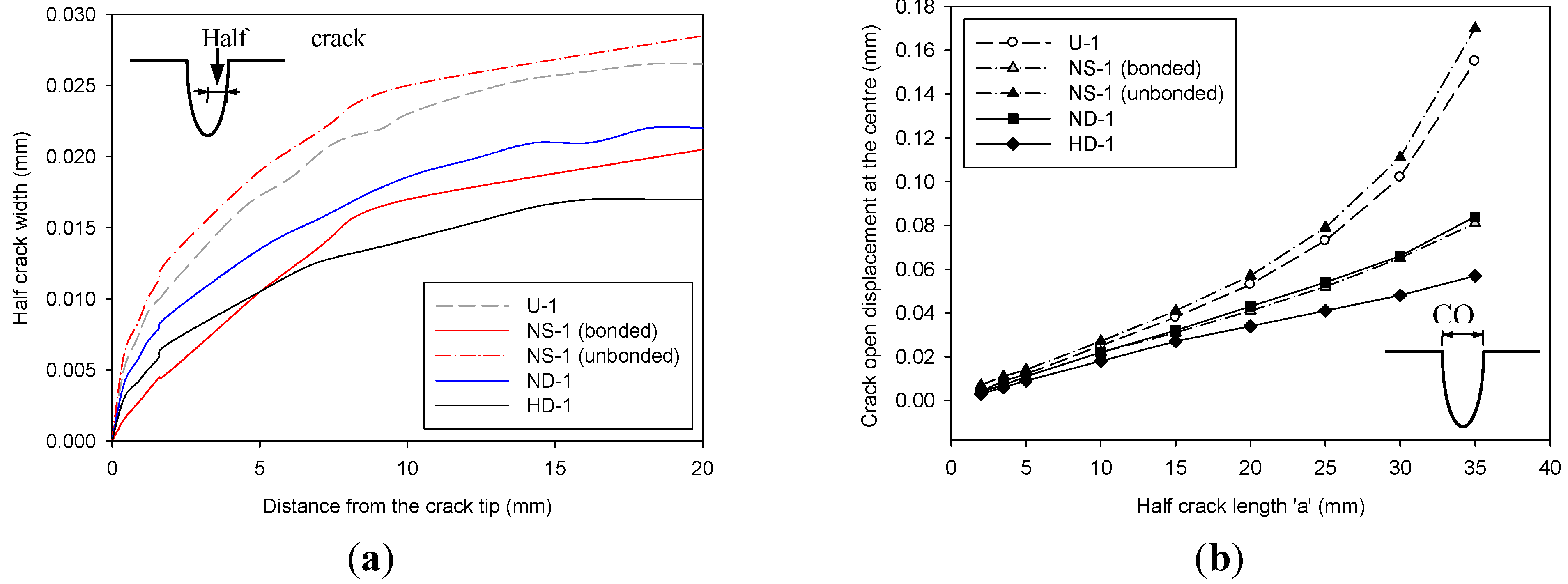
5.2. Crack Opening Displacement

5.3. Fatigue Life Prediction

6. Conclusions
Acknowledgments
Author Contributions
Conflicts of Interest
References
- Alsayed, S.H.; Al-Salloum, Y.A.; Almusallam, T.H. Fibre-reinforced polymer repair materials—some facts. Proc. ICE Civ. Eng. 2000, 138, 131–134. [Google Scholar] [CrossRef]
- Zhao, X.L.; Zhang, L. State-of-the-art review on FRP strengthened steel structures. Eng. Struct. 2007, 29, 1808–1823. [Google Scholar] [CrossRef]
- Teng, J.G.; Yu, T.; Fernando, D. Strengthening of steel structures with fiber-reinforced polymer composites. J. Constr. Steel Res. 2012, 78, 131–143. [Google Scholar] [CrossRef]
- Jones, S.C.; Civjan, S.A. Application of fibre-reinforced polymer overlays to extend steel fatigue life. J. Compos. Constr. 2003, 7, 331–338. [Google Scholar] [CrossRef]
- Täljsten, B.; Hansen, C.S.; Schmidt, J.W. Strengthening of old metallic structures in fatigue with prestressed and non-prestressed CFRP laminates. Constr. Build. Mater. 2009, 23, 1665–1677. [Google Scholar] [CrossRef]
- Liu, H.B.; Al-Mahaidi, R.; Zhao, X.L. Experimental study of fatigue crack growth behaviour in adhesively reinforced steel structures. Compos. Struct. 2009, 90, 12–20. [Google Scholar] [CrossRef]
- Wu, C.; Zhao, X.L.; Al-Mahaidi, R.; Emdad, M.R.; Duan, W.H. Fatigue tests of cracked steel plates strengthened with UHM CFRP plates. Adv. Struct. Eng. 2012, 15, 1801–1816. [Google Scholar] [CrossRef]
- Yu, Q.Q.; Zhao, X.L.; Al-Mahaidi, R.; Xiao, Z.G.; Chen, T.; Gu, X.L. Tests on cracked steel plates with different damage levels strengthened by CFRP laminates. Int. J. Struct. Stab. Dyn. 2014, 14, 1450018. [Google Scholar] [CrossRef]
- Colombi, P.; Fava, G.; Sonzogni, L. Effect of initial damage level and patch configuration on the fatigue behaviour of reinforced steel plates. Fatigue Fract. Eng. Mater. Struct. 2015, 38, 368–378. [Google Scholar] [CrossRef]
- Wang, H.T.; Wu, G.; Wu, Z.S. Effect of FRP configurations on the fatigue repair effectiveness of cracked steel plates. J. Compos. Constr. 2014, 18, 04013023. [Google Scholar] [CrossRef]
- Colombi, P.; Fava, G.; Sonzogni, L. Fatigue crack growth in CFRP-strengthened steel plates. Compos. Part B Eng. 2015, 72, 87–96. [Google Scholar] [CrossRef] [Green Version]
- Liu, H.B.; Zhao, X.L.; Al-Mahaidi, R. Boundary element analysis of CFRP reinforced steel plates. Compos. Struct. 2009, 91, 74–83. [Google Scholar] [CrossRef]
- Yu, Q.Q.; Zhao, X.L.; Chen, T.; Gu, X.L.; Xiao, Z.G. Crack propagation prediction of CFRP retrofitted steel plates with different degrees of damage using BEM. Thin-Walled Struct. 2014, 82, 145–158. [Google Scholar] [CrossRef]
- Yu, Q.Q.; Chen, T.; Gu, X.L.; Zhao, X.L. Boundary element analysis of edge cracked steel plates strengthened by CFRP laminates. Thin-Walled Struct 2015. Submitted for publication. [Google Scholar]
- Ghafoori, E.; Schumacher, A.; Motavalli, M. Fatigue behaviour of notched steel beams reinforced with bonded CFRP plates: Determination of prestressing level for crack arrest. Eng. Struct. 2012, 45, 270–283. [Google Scholar] [CrossRef]
- Jiao, H.; Mashiri, F.; Zhao, X.L. A comparative study on fatigue behaviour of steel beams retrofitted with welding, pultruded CFRP plates and wet layup CFRP sheets. Thin-Walled Struct. 2012, 59, 144–152. [Google Scholar] [CrossRef]
- Kim, Y.J.; Harries, K.A. Fatigue behavior of damaged steel beams repaired with CFRP strips. Eng. Struct. 2011, 33, 1491–1502. [Google Scholar] [CrossRef]
- Colombi, P.; Fava, G. Experimental study on the fatigue behaivour of cracked steel beams repaired with CFRP plates. Eng. Fract. Mech. 2015. [Google Scholar] [CrossRef] [Green Version]
- Ghafoori, E.; Motavalli, M. Normal, high and ultra-high modulus carbon fiber-reinforced polymer laminates for bonded and un-bonded strengthening of steel beams. Mater. Des. 2015, 67, 232–243. [Google Scholar] [CrossRef]
- Ghafoori, E.; Motavalli, M. Lateral-torsional buckling of steel I-beams retrofitted by bonded and un-bonded CFRP laminates with different pre-stress levels: Experimental and numerical study. Constr. Build. Mater. 2015, 76, 194–206. [Google Scholar] [CrossRef]
- Ghafoori, E.; Motavalli, M.; Botsis, J.; Herwig, A.; Galli, M. Fatigue strengthening of damaged metallic beams using prestressed unbonded and bonded CFRP plates. Int. J. Fatigue 2012, 44, 303–315. [Google Scholar] [CrossRef]
- Ghafoori, E.; Motavalli, M.; Nussbaumer, A.; Herwig, A.; Prinz, G.S.; Fontana, M. Determination of minimum CFRP pre-stress levels for fatigue crack prevention in retrofitted metallic beams. Eng. Struct. 2015, 84, 29–41. [Google Scholar] [CrossRef]
- Ghafoori, E.; Motavalli, M.; Nussbaumer, A.; Herwig, A.; Prinz, G.S.; Fontana, M. Design criterion for fatigue strengthening of riveted beams in a 120-year-old railway metallic bridge using pre-stressed CFRP plates. Compos. Part B Eng. 2015, 68, 1–13. [Google Scholar] [CrossRef]
- Ghafoori, E.; Motavalli, M.; Zhao, X.L.; Nussbaumer, A.; Fontana, M. Fatigue design criteria for strengthening metallic beams with bonded CFRP plates. Eng. Struct. 2015, 101, 542–557. [Google Scholar] [CrossRef]
- Xiao, Z.G.; Zhao, X.L. CFRP repaired welded thin-walled cross-beam connections subject to in-plane fatigue loading. Int. J. Struct. Stab. Dyn. 2012, 12, 195–211. [Google Scholar] [CrossRef]
- Chen, T.; Yu, Q.Q.; Gu, X.L.; Zhao, X.L. Study on fatigue behavior of strengthened non-load-carrying cruciform welded joints using carbon fibre sheets. Int. J. Struct. Stab. Dyn. 2012, 12, 179–194. [Google Scholar] [CrossRef]
- Koller, R.E.; Stoecklin, I.; Weisse, B.; Terrasi, G.P. Strengthening of fatigue critical welds of a steel box girder. Eng. Fail. Anal. 2012, 25, 329–345. [Google Scholar] [CrossRef]
- Koller, R.E.; Stoecklin, I.; Valet, S.; Terrasi, G.P. CFRP-strengthening and long-term performance of fatigue critical welds of a steel box girder. Polymers 2014, 6, 443–463. [Google Scholar] [CrossRef]
- Nakamura, H.; Jiang, W.; Suzuki, H.; Maeda, K.I.; Irube, T. Experimental study on repair of fatigue cracks at welded web gusset joint using CFRP strips. Thin-Walled Struct. 2009, 47, 1059–1068. [Google Scholar] [CrossRef]
- Wu, C.; Zhao, X.L.; Al-Mahaidi, R.; Emdad, M.R.; Duan, W.H. Fatigue tests on steel plates with longitudinal weld attachment strengthened by ultra high modulus carbon fibre reinforced polymer plate. Fatigue Fract. Eng. Mater. Struct. 2013, 36, 1027–1038. [Google Scholar] [CrossRef]
- Wang, Z.Y.; Wang, Q.Y. Fatigue strength of CFRP strengthened welded joints with corrugated steel plate. Compos. Part B Eng. 2015, 72, 30–39. [Google Scholar] [CrossRef]
- Chen, T.; Zhao, X.L.; Gu, X.L.; Xiao, Z.G. Numerical analysis on fatigue crack growth life of non-load-carrying cruciform welded joints repaired with FRP materials. Compos. Part B Eng. 2014, 56, 171–177. [Google Scholar] [CrossRef]
- Chen, T.; Yu, Q.Q.; Gu, X.L.; Nie, G.H. Stress intensity factors (KI) of cracked non-load-carrying cruciform welded joints repaired with CFRP materials. Compos. Part B Eng. 2013, 45, 1629–1635. [Google Scholar] [CrossRef]
- Yu, Q.Q.; Chen, T.; Gu, X.L.; Zhao, X.L.; Xiao, Z.G. Boundary element analysis of fatigue crack growth for CFRP strengthened steel plates with longitudinal weld attachment. J. Compos. Constr. 2015, 19, 04014044. [Google Scholar] [CrossRef]
- Chen, T.; Yu, Q.Q.; Gu, X.L.; Zhao, X.L. Fatigue Test on Out-of-Plane Gusset Welded Joints Strengthened with Carbon Fiber Reinforced Polymer Materials. In Proceedings of the 3rd Asia-Pacific Conference on FRP in Structures, Hokkaido, Japan, 2–4 February 2012.
- Code for Design of Steel Structures; GB 50017-2003; China Planning Press: Beijing, China, 2003.
- Metallic Materials—Tensile Testing at Ambient Temperature; GB/T 228–2002; China Architecture & Building Press: Beijing, China, 2002.
- Fawzia, S. Bond characteristics between steel and carbon fibre reinforced polymer (CFRP) composites. PhD Thesis, Monash University, Melbourne, Australia, 2007. [Google Scholar]
- Nguyen, T.C.; Bai, Y.; Zhao, X.L.; Al-Mahaidi, R. Mechanical characterization of steel/CFRP double strap joints at elevated temperatures. Compos. Struct. 2011, 93, 1604–1612. [Google Scholar] [CrossRef]
- Nguyen, T.C.; Bai, Y.; Al-Mahaidi, R.; Zhao, X.L. Time-dependent behaviour of steel/CFRP double strap joints subjected to combined thermal and mechanical loading. Compos. Struct. 2012, 94, 1826–1833. [Google Scholar] [CrossRef]
- Hollaway, L.C.; Cadei, J. Progress in the technique of upgrading metallic structures with advances polymer composites. Prog. Struct. Eng. Mater. 2002, 4, 131–148. [Google Scholar] [CrossRef]
- Mall, S.; Ramamurthy, G. Effect of bond thickness on fracture and fatigue strength of adhesively bonded composite joints. Int. J. Adhes. Adhes. 1989, 9, 33–37. [Google Scholar] [CrossRef]
- Lam, A.C.C.; Cheng, J.J.R.; Yam, M.C.H.; Kennedy, G.D. Repair of steel structures by bonded carbon fibre reinforced polymer patching: experimental and numerical study of carbon fibre reinforced polymer-steel double-lap joints under tensile loading. Can. J. Civ. Eng. 2007, 34, 1542–1553. [Google Scholar] [CrossRef]
- Recommendations for Fatigue Design of Welded Joints and Components; IIW document IIW-1823–07 ex XIII-2151–07/XV-1254–07; International Institute of Welding: Graz, Austria, 2008.
- Amiri, A.; Cavalli, M.N. Experimental investigation of fatigue behavior of carbon fiber composites using fully reversed four point bending test. Compos. Mater. Join. Technol. Compos. 2013, 7, 131–137. [Google Scholar]
- Tomita, Y.; Morioka, K.; Iwasa, M. Bending fatigue of long carbon fiber-reinforced epoxy composites. Mater. Sci. Eng. A 2001, 319–321, 679–682. [Google Scholar] [CrossRef]
- Monfared, A.; Soudki, K.; Walbridge, S. CFRP Reinforcing to Extend the Fatigue Lives of Steel Structures. In Proceedings of the 4th International Conference on FRP composites in Civil Engineering, Zurich, Switzerland, 22–24 July 2008.
- Steel Structures; AS 4100–1998; Standards Association of Australia: Sydney, Australia, 1998.
- Eurocode 3: Design of steel structures. Part 1–9: Fatigue; British Standards Institution: Brussels, Belgium, 2005.
- Fatigue Design and Assessment of Steel Structures; BS 7608:1993; British Standards Institution: Brussels, Belgium, 1993.
- Fatigue Design Recommendations for Steel Structures; Japanese Society of Steel Construction: Tokyo, Japan, 1995.
- Baumgartner, J.; Bruder, T. Influence of weld geometry and residual stresses on the fatigue strength of longitudinal stiffeners. Weld. World 2013, 57, 841–855. [Google Scholar] [CrossRef]
- ABAQUS, version 6.11; a software suite for finite element analysis; SIMULIA Inc: Providence, RI, USA, 2010.
- Colombi, P.; Bassetti, A.; Nussbaumer, A. Analysis of cracked steel members reinforced by pre-stress composite patch. Fatigue Fract. Eng. Mater. Struct. 2003, 26, 59–66. [Google Scholar] [CrossRef]
- Elber, W. Fatigue crack closure under cyclic tension. Eng. Fract. Mech. 1970, 2, 37–45. [Google Scholar]
- Liu, H.B.; Xiao, Z.G.; Zhao, X.L.; Al-Mahaidi, R. Prediction of fatigue life for CFRP strengthened steel plates. Thin-Walled Struct. 2009, 4, 1069–1077. [Google Scholar] [CrossRef]
- Guide to Methods for Assessing the Acceptability of Flaws in Metallic Structures; BS7910:2005; British Standards Institution: Brussels, Belgium, 2005.
© 2015 by the authors; licensee MDPI, Basel, Switzerland. This article is an open access article distributed under the terms and conditions of the Creative Commons Attribution license (http://creativecommons.org/licenses/by/4.0/).
Share and Cite
Yu, Q.-Q.; Chen, T.; Gu, X.-L.; Zhang, N.-X. Fatigue Behaviour of CFRP Strengthened Out-of-Plane Gusset Welded Joints with Double Cracks. Polymers 2015, 7, 1617-1637. https://doi.org/10.3390/polym7091475
Yu Q-Q, Chen T, Gu X-L, Zhang N-X. Fatigue Behaviour of CFRP Strengthened Out-of-Plane Gusset Welded Joints with Double Cracks. Polymers. 2015; 7(9):1617-1637. https://doi.org/10.3390/polym7091475
Chicago/Turabian StyleYu, Qian-Qian, Tao Chen, Xiang-Lin Gu, and Ning-Xi Zhang. 2015. "Fatigue Behaviour of CFRP Strengthened Out-of-Plane Gusset Welded Joints with Double Cracks" Polymers 7, no. 9: 1617-1637. https://doi.org/10.3390/polym7091475