Article

Polyaniline-Doped Spherical Polyelectrolyte Brush Nanocomposites with Enhanced Electrical Conductivity, Thermal Stability, and Solubility Property

School of Printing and Packaging Engineering, Shanghai Publishing and Printing College, Shanghai, 200093, China
Polymers 2015, 7(9), 1599-1616; https://doi.org/10.3390/polym7091473
Submission received: 11 July 2015 / Accepted: 19 August 2015 / Published: 2 September 2015

Abstract

:
The synthesis procedure and dopant are crucial to the electrical conductivity, thermal stability, and solubility properties of polyaniline (PANI). In this paper, high-performance PANI was synthesized by means of chemical oxidative polymerization using anionic spherical polyelectrolyte brushes (ASPB) as dopant. The bonding structure, crystallographic structure, morphology, and thermal stability of the conductive nanocomposite were analyzed by Fourier transform infrared spectroscopy (FTIR), X-ray diffraction (XRD), scanning electron microscopy (SEM), and thermo-gravimetric analysis (TGA) respectively. Meanwhile, investigation on the electrical conductivity suggested that the room-temperature electrical conductivity of PANI doped with ASPB (PANI/ASPB) was 19.3 S/cm, which was higher than that of PANI (7.0 S/cm), PANI doped with poly(sodium-p-styrenesulfonate) (PSS) (PANI/PSS) (14.6 S/cm), PANI doped with SiO2 (PANI/SiO2) (18.2 S/cm), and PANI doped with canonic spherical polyelectrolyte brushes (CSPB) (PANI/CSPB) (8.0 S/cm). Meanwhile, the addition of ASPB improved the thermal stability and solubility properties of PANI. ASPB played the role of template. Conductive mechanism of PANI/ASPB nanocomposite can be explained by the theoretical models of three-dimensional variable range-hopping (3D VRH).

Graphical Abstract

1. Introduction

In recent years, the new term “Internet of Things” (IOT) frequently appears on people’s horizons, especially those living in the era of rapid development of information [1,2]. IOT is a network which can encode and recognize things using the radio frequency identification (RFID) technology. Any article can exchange information and communicate by connecting to Internet, so as to achieve the intelligent recognition of objects, positioning, tracking, monitoring, and management [3,4,5,6]. Etching has always been the most common method of making RFID antennas. This approach must go through two processes of dry etching and wet etching. Wet etching is difficult to reduce production costs [7]. At the same time, it is also not environmentally friendly because it needs to be treated with a chemical process, producing large amounts of waste liquor. While printing RFID antennas by conductive ink is only needed to go through a dry process with little waste liquor, lower scrap rates, and stable antenna performance, mass production and a significantly-reduced production cost can be achieved. Therefore, the application of conductive ink in RFID is an inevitable trend. In view of this, how to get conductive ink with excellent properties is the focus of our research.
With the development of printed electronics, three development trends of conductive ink have merged: organic ink, nanomaterials, and printed silicon [8,9,10]. Conducting polymers, as one of irreplaceable organic materials, can be used in almost all emerging industries and modern high-tech fields. Among the extensive studies of conducting polymers involving polyaniline (PANI), polypyrrole (PPy) [11,12], and polythiophene (PT), PANI has attracted attention recently due to its ready availability, simple synthesis, excellent electrical and optical properties, magnetoresistance (MR) behaviors, and thermal stability [13,14,15,16]. However, large-scale application of PANI is limited except for improving its insolubility and infusibility. Consequently, many studies have focused on the synthesis of PANI with suitably-modified structures by “doping” [17,18,19,20]. It is encouraging that the doped PANI not only possesses high electrical conductivity, but also has good solubility properties. Thus, it is a promising new material for the preparation of conductive ink. In consideration of this fact, anionic spherical polyelectrolyte brushes (ASPB) with spherical structure and charged chains may be a novel dopant of conducting polymers. For one thing, its spherical structure can provide the growth direction for conducting polymers, and the properties of conducting nanocomposites are improved by well-controlling the length of grafted brushes and/or the amount of ASPB in the PANI/ASPB nanocomposites. For another, as one of three development trends of conductive ink, nano-silica is selected as the cores of ASPB.
The aim of this paper is to obtain PANI conducting nanocomposite with excellent electrical conductivity, thermal stability, and solubility properties by using ASPB as dopant. On the basis of previous work [21], PANI, ASPB consisting of SiO2 cores and poly(sodium-p-styrenesulfonate) (PSS) brushes [22], and PANI doped with PSS, SiO2, and canonic spherical polyelectrolyte brushes (CSPB) were also synthesized. A variety of characterization and analytical methods were used to investigate the structure and properties of conducting nanocomposites. Based on this evidence, the doping mechanism of ASPB was explored. Furthermore, electrical conductivity, which was crucial to conducting polymers and their effects, factors such as polymerization temperature and time, the molecular weight of grafted polyelectrolyte brushes, and the amount of ASPB were also discussed.

2. Experimental Section

2.1. Raw Materials and Reagents

Aniline monomer (Sinopharm of Chemical Reagents Co., Ltd., Shanghai, China) was distilled under reduced pressure before use. Other chemicals and solvents such as ammonium persulfate (APS, 98%, Sinopharm of Chemical Reagents Co., Ltd., Shanghai, China), sodium-p-styrenesulfonate (SSS), Hydrochloric acid (HCl, 36%–38%), and ethanol were analytical reagents and were used without further purification. Monodisperse spherical SiO2 nanoparticles (ca. 100 nm) were prepared using tetraethoxysilane by sol-gel method. The ASPB (Dz ≈ 100 nm, Mw = 500–2000 g/mol) consisting of SiO2 cores and PSS brushes and CSPB (Dz ≈ 100 nm, Mw = 2000 g/mol) consisting of SiO2 cores and poly (diallyl dimethyl ammonium chloride) (p-DMMPAC) brushes were prepared by surface-initiated polymerization.

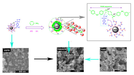
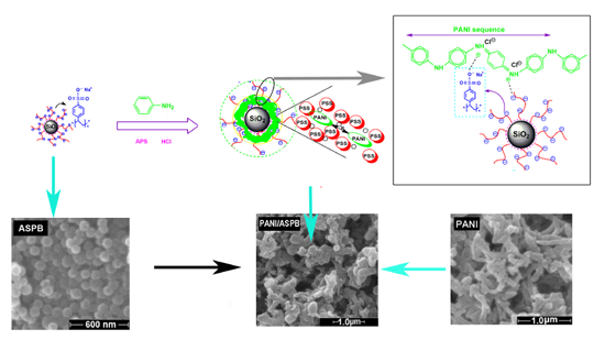
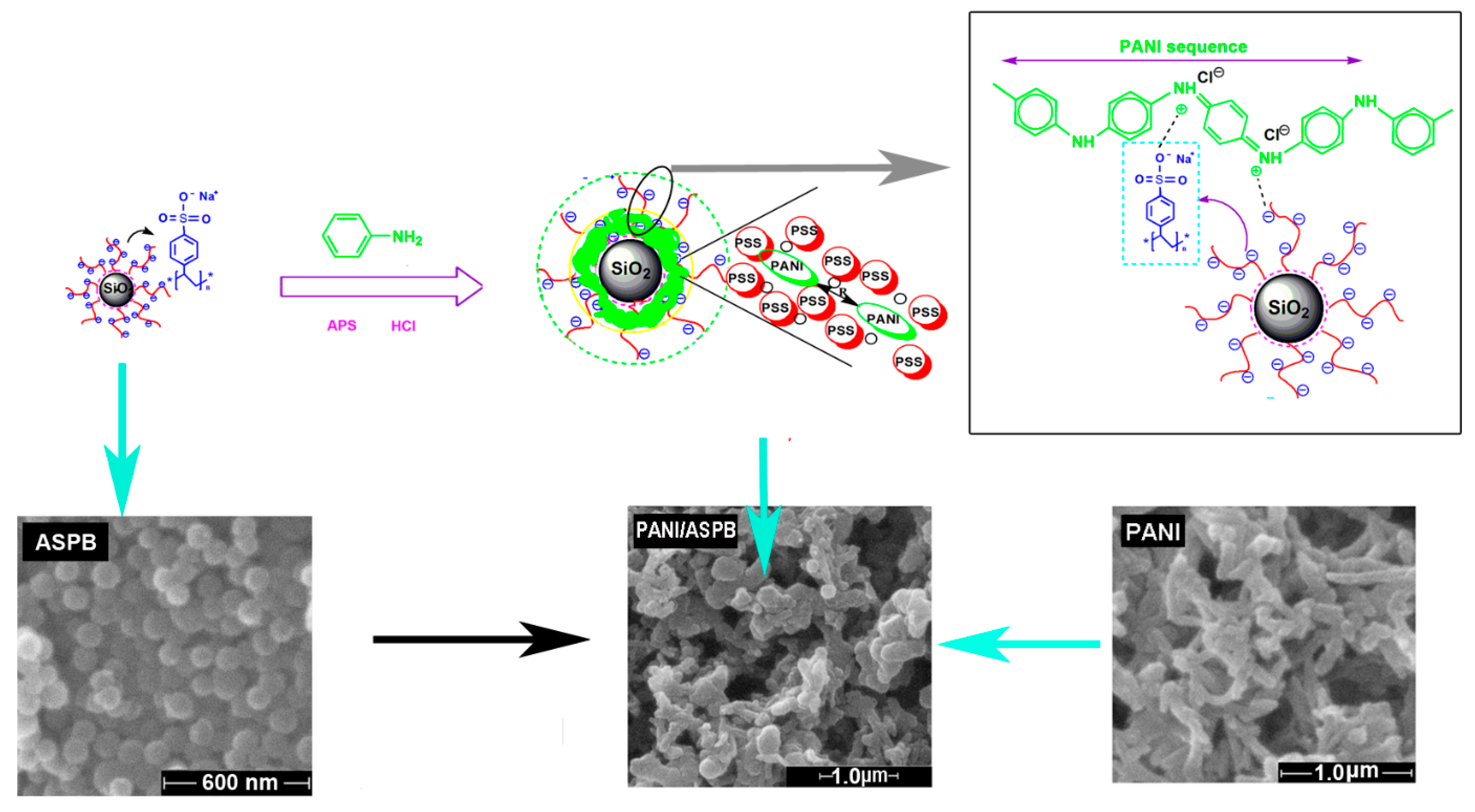
2.2. Preparation of PANI/ASPB Nanocomposite

In a typical set of synthesis, 76.5 mg of ASPB was firstly dispersed in 31.5 mL of 2 M HCl (aq.) by ultrasonic dispersion machine for 20 min followed by addition of 1.5 mL of aniline. The mixture was cooled to 5 °C and stirred for 20 min in a N2 atmosphere. APS (3.75 g) was then added to above mixture. Polymerization was allowed to proceed for 6 h. The resultant products were collected after repeated filtration, washing with ethanol and distilled water, and drying overnight in vacuum at 60 °C. For the purpose of exploring the doping effect of different dopants (PSS, SiO2, and CSPB) on the electrical conductivity, PANI, PANI/PSS, PANI/SiO2, and PANI/CSPB nanocomposites were also synthesized.

2.3. Structural and Morphological Analysis

The products were investigated by Scanning Electron Microscope (SEM, Quanta 200 FEI, Netherlands, operated at 30 kV), Fourier transform infrared spectroscopy (FTIR, Nicolet AVATAR 360FT; Thermo Fisher Scientific Inc.: Waltham, MA, USA), Ultraviolet-visible spectroscopy (UV-VIS, Shimadzu “UV-240”; Shimadzu Corporation: Kyoto, Japan), and X-ray diffraction (XRD, Shimadzu “XRD-6000”; Shimadzu Corporation: Kyoto, Japan, operated at a voltage of 40 kV and a current of 40 mA with CuKα radiation, λ = 1.54060 Å). The samples for UV-VIS spectroscopy measurement were dissolved in the ethanol solution (1 mg of samples diluted in 10 mL of ethanol), and the samples for XRD experiment were measured in a continuous scan mode at 5–50° (2θ) with a scanning rate of 5°/min.

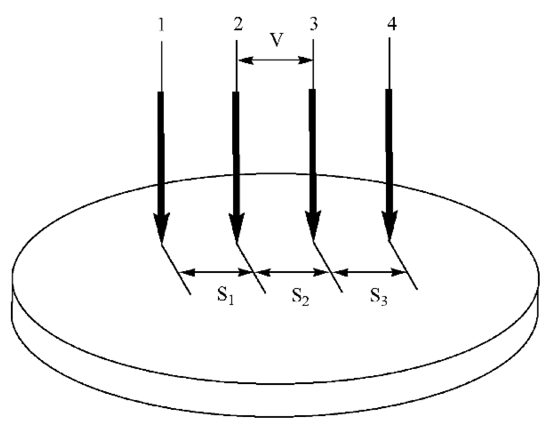
2.4. Performance Tests

The thermal stability of samples was studied by thermo-gravimetric analysis (TGA), which was performed on a SETSYS-1750 instrument (SETARAM Instrumentation, Caluire, Lyon, France) at a heating rate of 10 °C/min under N2 atmosphere. The measurement of electrical conductivity was carried out on a four-point probe (RTS-4, Shanghai, China) apparatus at room temperature.
The samples were firstly pressed into the circular tablet with a diameter of 13 mm at 20 MPa, the thickness W (>1 mm) of each tablet was then measured. As displayed in Figure 1, four metal probes were lined up. I denote the current between probe 1 and probe 4, V denote the potential difference between probe 2 and probe 3, and S denote the distance of adjacent probe (S1 = S2 = S3 = 1 mm). The resistivity ρ and source current I could be calculated using the following equations [23]:
ρ = V I C
I = F ( W / S ) × F ( D / S ) × W × 0.1
σ = 1 ρ
As the probe factor, C is determined by the geometric position of probe. F (W/S) is the width correction coefficient, and F (D/S) (S = 1) is the diameter correction coefficient. They are all taken from a reference.
Figure 1. Schematic representation of four-point probe resistivity measurement.
Polymers 07 01473 g001
With the purpose of understanding the solubility properties of the samples, which was reflected by the conductivity of saturated solution (T = 25 °C, pH = 6), the solubility experiment was performed using DDS-12A digital conductivity meter (Hubei Provincial Institute of Measurement and Testing, Wuhan, China). Ten milligrams of samples were firstly dissolved in 4 mL of ethanol. After being stirred and heated to boiling, the mixture was subjected to remove the supernatant and soluble impurities. The process above was repeated twice. Ten milliliters of ethanol was then added and heated to boiling so as to fully dissolve the samples. The samples were placed in a constant temperature bath for 20 min to precipitate the solid. Since the solid particles suspended in the electrode might affect the test result, 3 or 4 mL of supernatant was placed into the beaker. The conductivity of saturated solution of ethanol was measured prior to carrying out the experiment as a reference.

3. Results and Discussion

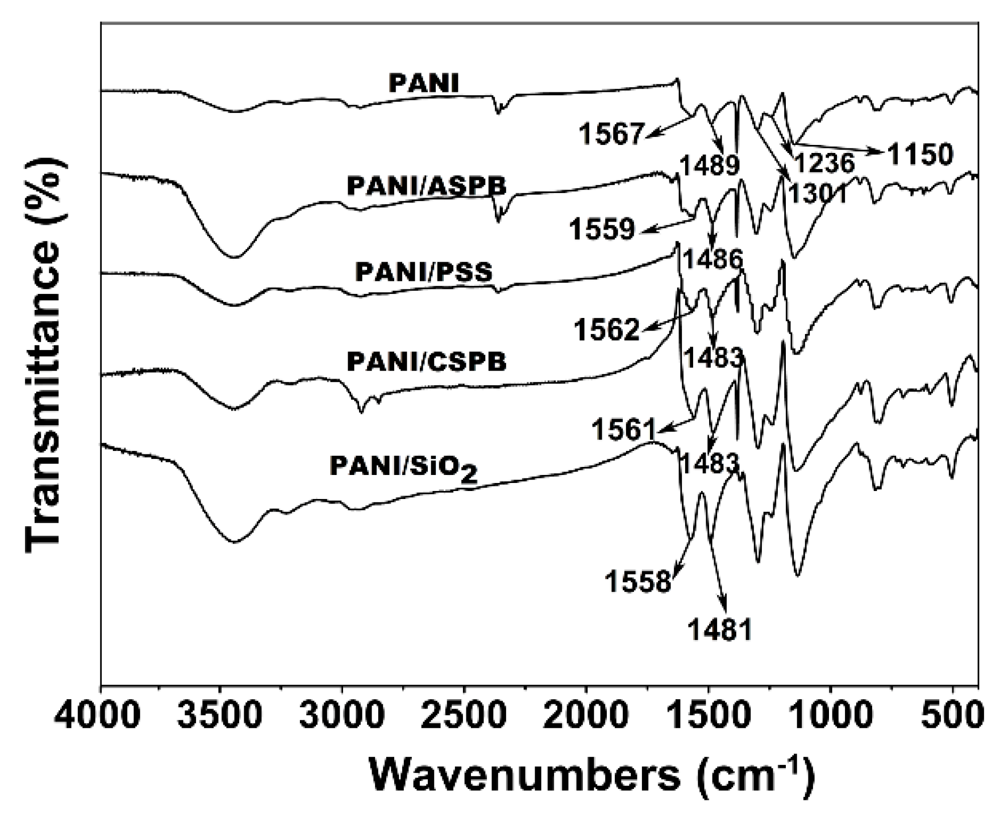
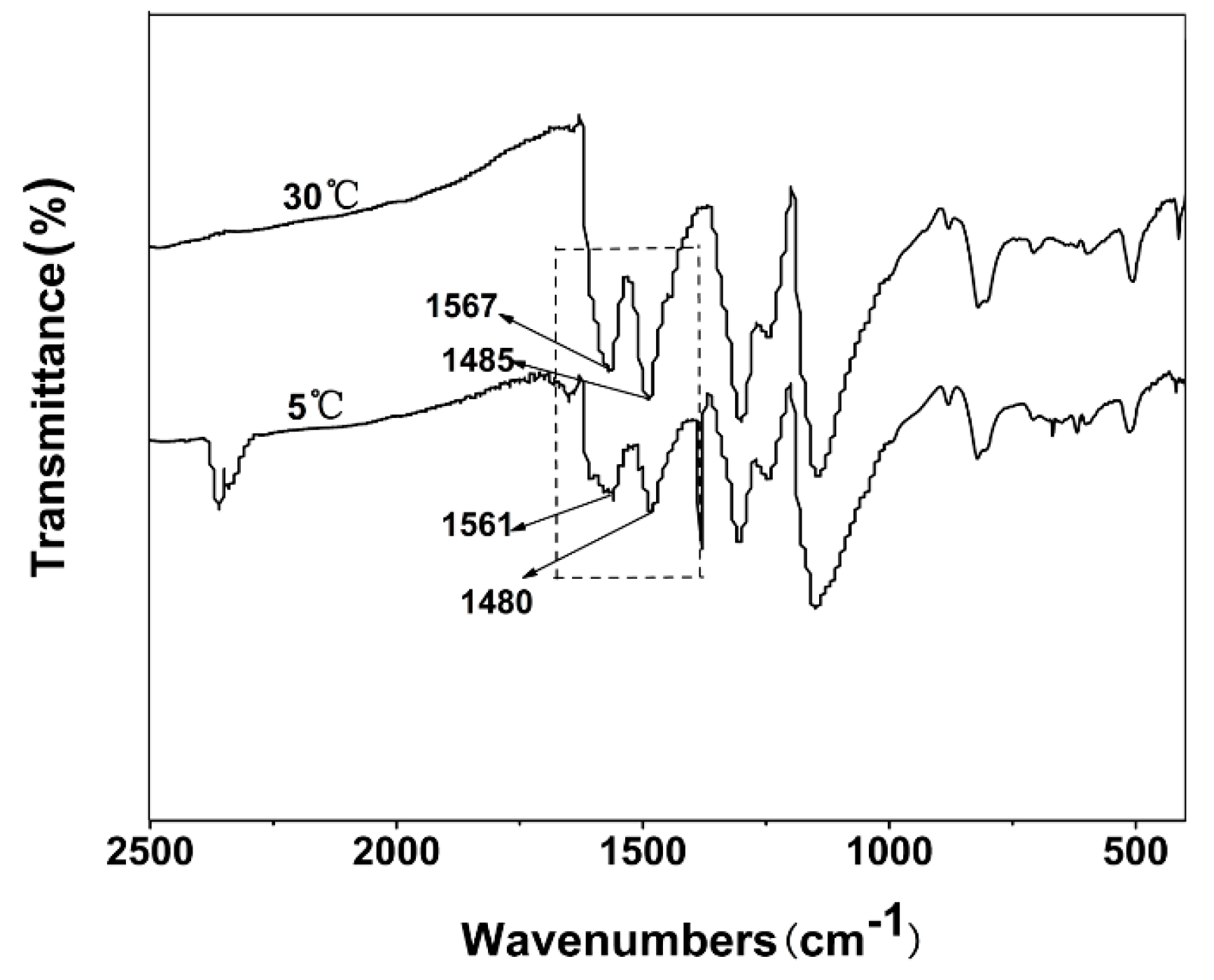
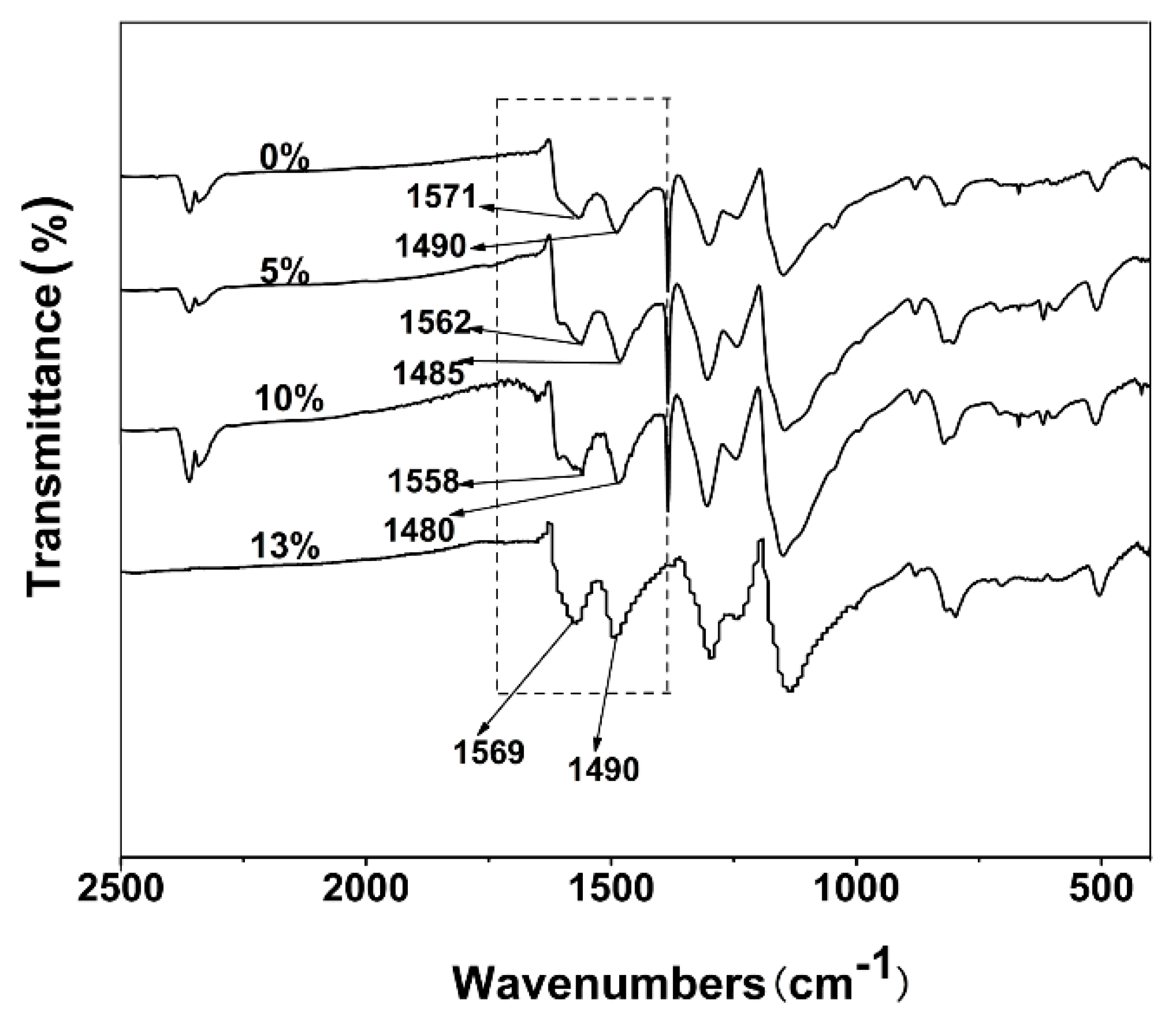
3.1. Structural Analysis-FTIR Spectra

The chemical structure of samples is monitored by FTIR spectroscopy (Figure 2). The protonated PANI shows strong peaks at 1567 and 1489 cm−1 corresponding to the stretching vibration of the quinonoid and benzenoid rings, and the peaks at 1301 and 1203 cm−1 can be assigned to C–N and C=N stretching vibrations respectively, which are coincident with the literature [24]. In presence of ASPB, PSS, CSPB and SiO2, no new peaks appear, indicating that the dopant ions have no effect on the structure of PANI chains. It is a further evidence of proton acid doping for PANI. Meanwhile, the positions of two characteristic absorption peaks of a quinone ring and a benzene ring have shifted to the low wavenumber by doping, which may be due to the enhancement of delocalization of charge electron by chemical oxidative polymerization doping [25]. However, the extent of shift is slightly different. When doped with ASPB and SiO2, larger shifts than doping with PSS and CSPB for the above two peaks occurs, indicating that the charge delocalization in PANI chains may be strong, and the electrical conductivity increases. The increase in electrical conductivity is further confirmed by the delocalization effects of radical cation.
Figure 2. FTIR spectra of PANI, PANI/ASPB, PANI/PSS, PANI/CSPB, and PANI/SiO2 nanocomposites.
Polymers 07 01473 g002

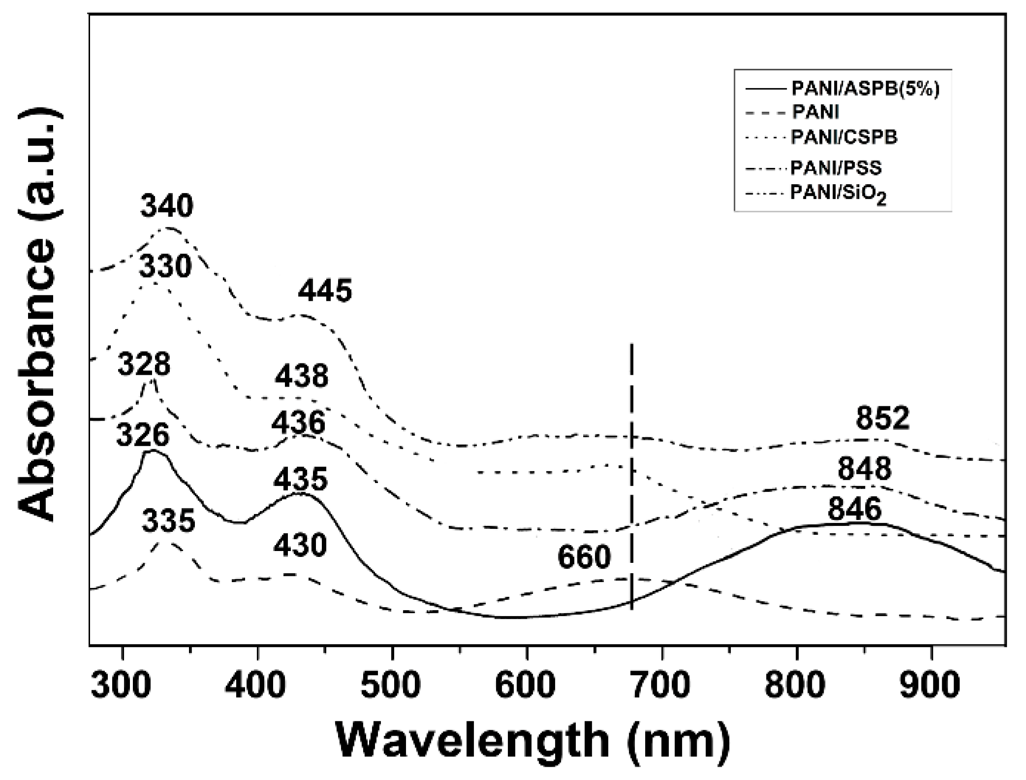
3.2. Structural Analysis—UV-VIS Spectra

Figure 3 displays the UV-VIS absorption spectra of all the samples. Take PANI for example, the absorption peak corresponding to π–π* electronic transition for the quinone ring is clearly present at 335 nm, and the absorption peak at 660 nm is attributed to the charge transfer of the quinone imine ring [26]. In addition, with all PANI doped with acid a new peak appears around 430 nm, corresponding to the polaron absorption peak [27]. For PANI doped with ASPB, PSS, and SiO2, a broad peak around 846 nm turns up, which also originated from the formation of polarons in PANI chains. These new peaks suggest delocalization and electron conduction. Meanwhile, the absorption peaks at 660 nm disappear. This shows that the delocalization of PANI chains can be increased, along with the extension of effective conjugation length for PANI chains [28].
Figure 3. UV-VIS spectra of PANI, PANI/ASPB, PANI/PSS, PANI/CSPB, and PANI/SiO2 nanocomposites.
Polymers 07 01473 g003

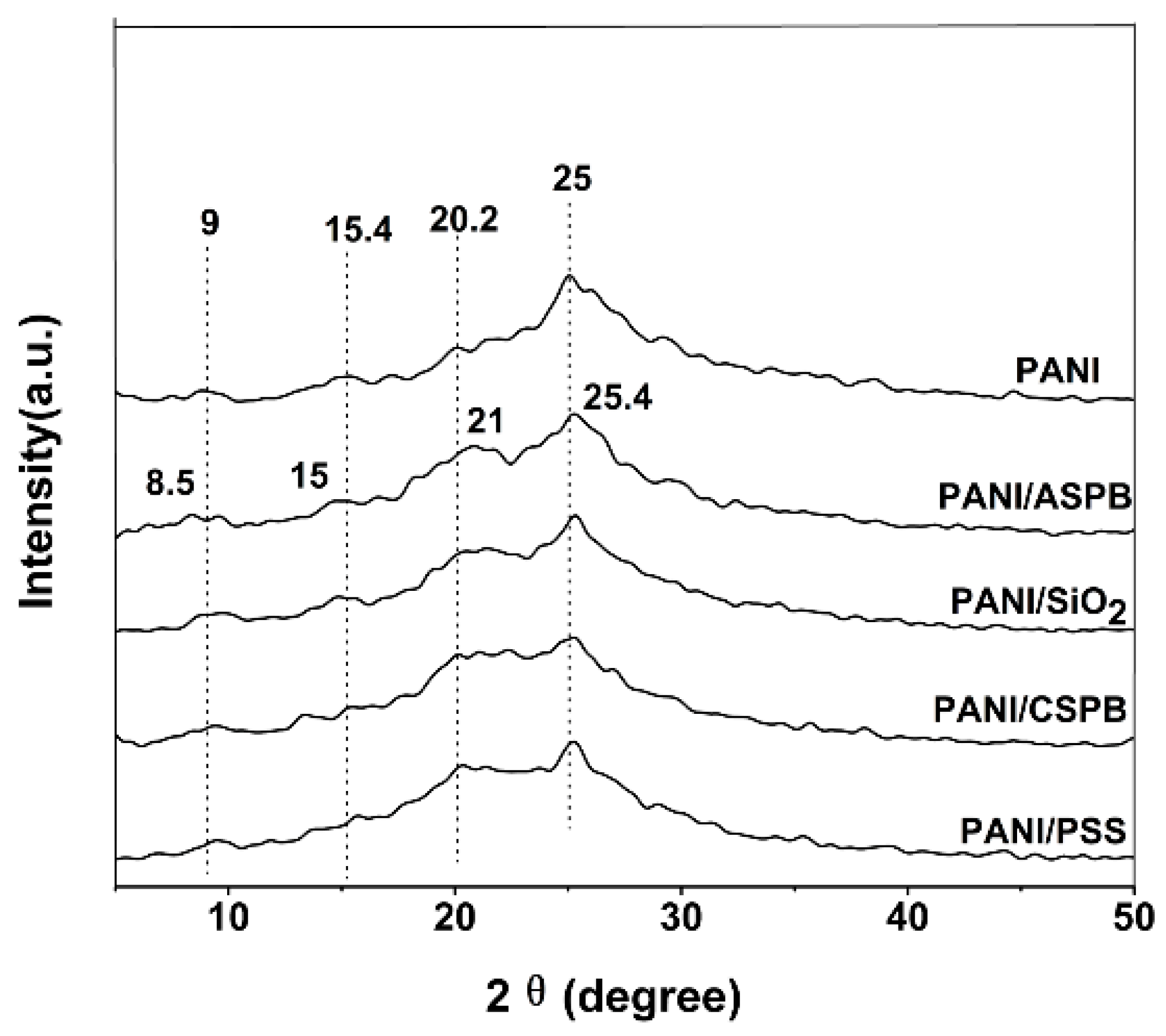
3.3. Structural Analysis—XRD Patterns

Studies have shown that the stretched PANI chains are easier to crystallize than the curled PANI chains. This is due to the fact that stretch conformation makes the distance among the PANI chains short, leading to a high crystallinity. Additionally, the stretch of polymer chains enhances delocalization of polaron energy bands, increasing the mobility and conductivity of the carrier in the chains. Figure 4 displays the XRD patterns of PANI doped with different dopants. The main peaks at 2θ = 9°, 15.4°, 20.2°, and 25° for the XRD pattern of PANI are attributed to the structure of parallel, periodically interlaced with vertical in polymer chains [29]. When dopants are added, as the ratio of [Cl]/[N] in nanocomposite is decreased, the intensity of the peaks at 2θ = 21° is increased [30], and the changes of position and intensity for remaining peaks take place. When doped with ASPB and SiO2, the shape of two peaks was similar, and the peak positions have shifted to 2θ = 8.5°, 15°, 21° and 25.4° respectively. According to the Prague formula (2dsinθ = nλ), the interplanar distance (d) is 1.06 nm, 0.58 nm, 0.42 nm, 0.35 nm separately when the diffraction peaks are 2θ = 8.5°, 15°, 21° and 25.4°. The full width at half maximum (FWHM) of PANI, PANI/ASPB and PANI/SiO2 at 2θ = 25°, 2θ = 25.4° is 2.4°, 3°, and 2°, respectively, which indicates that the crystallinity of conducting nanocomposites increases by doping with SiO2. It can be considered that the formation of the ordered structure for benzene is promoted by addition of ASPB and SiO2, helping the plane scattering between the benzene ring [31]. However, the increase in crystallization means a larger particle size for nanocomposites, and the solubility is degraded. For PANI/ASPB nanocomposite, the FWHM increases, demonstrating it has low crystallinity and small particle size. Therefore, the solubility of PANI/ASPB nanocomposite is improved. For the PANI/PSS and PANI/CSPB nanocomposites, peaks are broadened, indicating that the particle size becomes smaller. This may be because the flexible chains of PSS prevent the growth of PANI chains. While the peaks are not very clear for PANI/CSPB nanocomposite, indicating the crystallinity degree of the nanocomposite is poor.
Figure 4. XRD patterns of PANI, PANI/ASPB, PANI/PSS, PANI/CSPB, and PANI/SiO2 nanocomposites.
Polymers 07 01473 g004

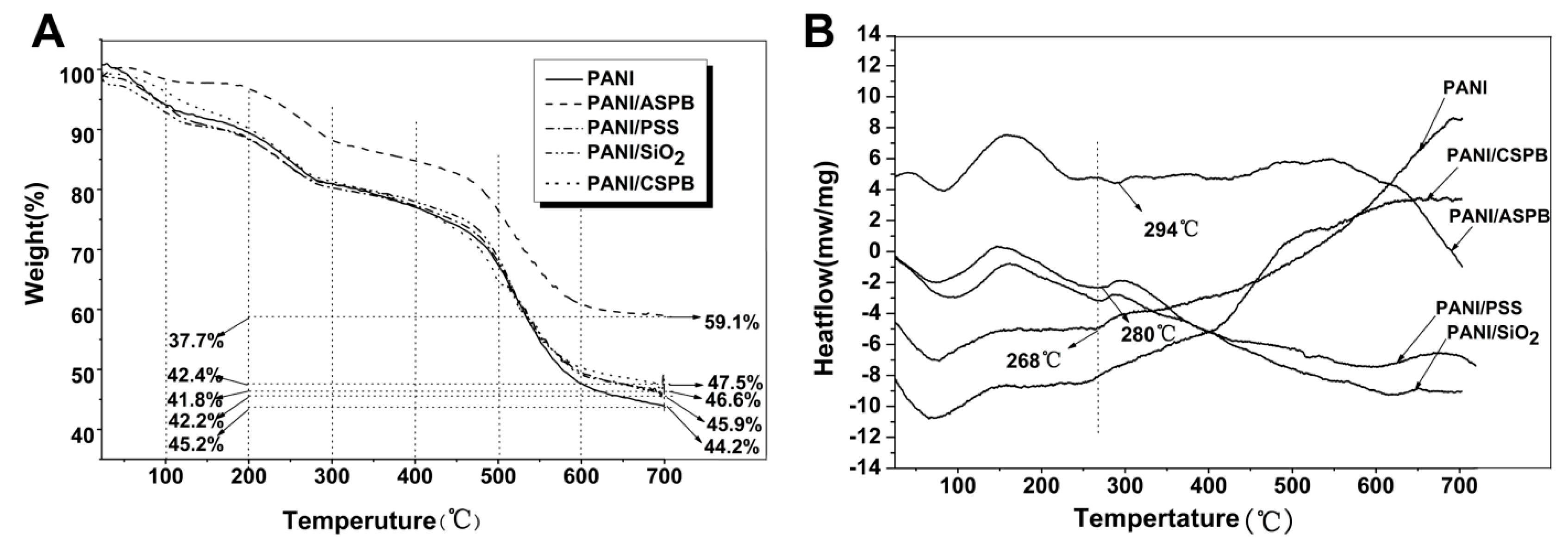
3.4. Thermal Stability
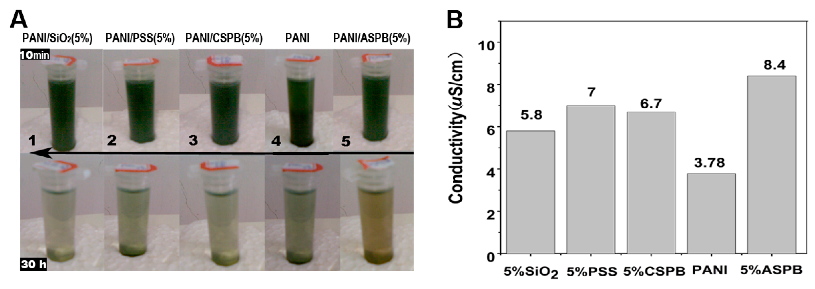
The thermal stability of conductive nanocomposites is investigated by TGA (under N2 atmosphere). As shown in Figure 5, nearly 7.9 wt % weight loss has occurred at 100 °C because PANI is hygroscopic, while only 2 wt % weight loss for PANI/ASPB nanocomposite due to the evaporation of residual water. With the increasing of temperature, main mass loss for PANI, PANI/ASPB, PANI/PSS, PANI/CSPB, and PANI/SiO2 nanocomposites starts at about 200 °C because of PANI degradation [32]. The mass loss at 200–700 °C for all the conductive nanocomposites is calculated as follows: PANI = 45.2%, PANI/SiO2 = 41.8%, PANI/CSPB = 42.6%, PANI/PSS = 42.4%, PANI/ASPB = 37.7%. Compared with PANI, the mass loss for PANI/ASPB and PANI/ SiO2 nanocomposites is decreased by 3.4% and 7.5% respectively, indicating that the thermal stability can be improved by doping with the two dopants. It is of importance for the preparation of high-performance conductive nanocomposites. While the effects of PSS and CSPB for improving the thermal stability of PANI are not obvious. The DSC curves of PANI with different dopants are also displayed in Figure 5. The thermal decomposition temperatures of PANI/ASPB and PANI/SiO2 are at 294 and 280 °C respectively, which are higher than that of PANI (268 °C). Thus, the thermal stability of PANI can be improved by doping with ASPB and SiO2. On one hand, SiO2 and ASPB possess a high thermal stability. On the other hand, the interaction between the dopants and PANI chains may be enhanced by the addition of SiO2 and ASPB, thus increasing the orderliness of PANI chains. As a result, a stable structure of molecule chains is obtained.
Figure 5. (A) TGA curves and (B) DSC curves of PANI, PANI/ASPB PANI/PSS, PANI/CSPB, and PANI/SiO2 nanocomposites.
Polymers 07 01473 g005

3.5. Solubility

The solubility of samples is shown in Figure 6. It is reflected by the conductivity of saturated solution (T = 25 °C, pH = 6). As demonstrated by Figure 6A, the conductive nanocomposites with different dopants (0.01 g) are firstly dispersed in ethanol (4 mL) by ultrasonic dispersion machine for 10 min, and then maintained for a long time. Thirty hours later, the solution of conductive nanocomposite with good solubility should be green. We can see that the solutions are clear for the PANI/SiO2 and PANI/CSPB nanocomposites, while dark green is shown for the solutions of PANI/PSS and PANI/ASPB nanocomposites, indicating that these two nanocomposites have good solubility. The reason for this is that the flexible long PSS chains make the resulting PANI chains short and small, thereby inducing the dissolution of conductive nanocomposite. A poor solubility is obtained by addition of SiO2, which is mainly due to the increase of the crystallinity of conductive nanocomposite. This result is in accordance with the XRD studies. Additionally, Figure 6B shows the quantitative analysis method. After understanding the conductivity of saturated solution of ethanol (0.2 μS/cm), the conductivities of saturated solution of PANI/ASPB, PANI/SiO2, PANI/PSS, PANI/CSPB, and PANI are 8.4, 5.8, 7.0, 6.7, and 3.78 μS/cm, respectively. So the contributions of different dopants on solubility properties of conductive nanocomposites follow the order: ASPB > PSS > CSPB > SiO2.
Figure 6. (A) Qualitative and (B) quantitative analysis of the conductivity of saturated solution of PANI, PANI/ASPB, PANI/PSS, PANI/CSPB, and PANI/SiO2 nanocomposites (T = 25 °C, pH = 6).
Polymers 07 01473 g006

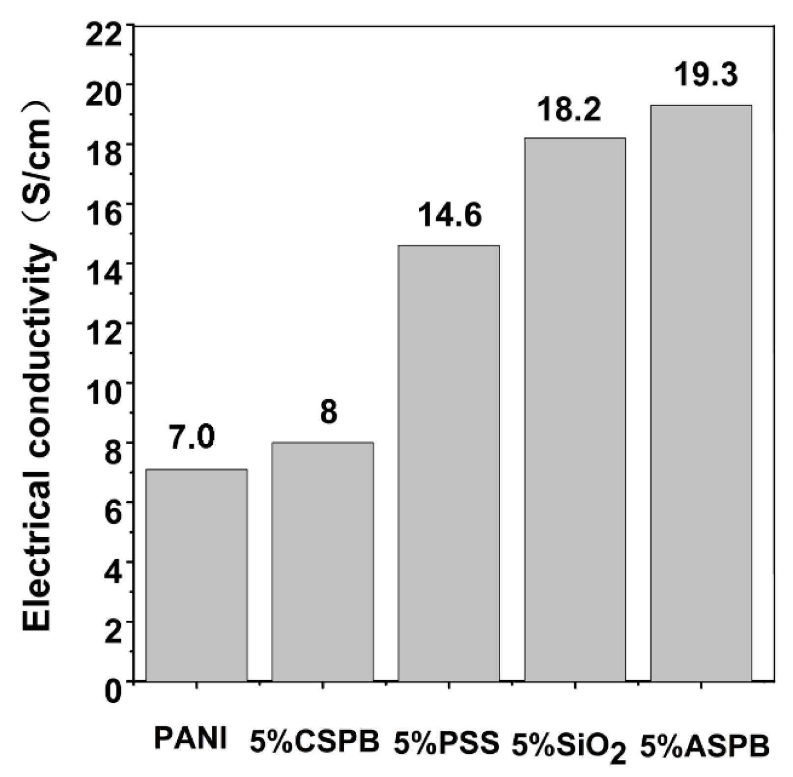
3.6. Evaluation of Dopants

In a word, the effects of different dopants on PANI are different, which is proved by a variety of characterization methods. When the amount of dopants is 5 wt %, the performances of PANI are displayed in Table 1.
Table 1. Table 1.Effect of dopant species on the properties of PANI.
PropertiesSamples
PANIPANI/ASPBPANI/SiO2PANI/PSSPANI/CSPB
Electrical conductivity (S/cm)7.019.318.214.68
Conductivity of saturated solution (μS/cm)3.788.45.876.7
Exothermic peak (°C)268294280270inconspicuous
It can be seen from the table that the contributions of each dopant on electrical conductivity, thermal stability and solubility of PANI follow the order: ASPB > SiO2 > PSS> CSPB, ASPB > SiO2 > PSS > CSPB and ASPB > PSS > CSPB > SiO2, respectively. When doped with SiO2, the structure regularity of PANI may be increased according to the literature [32], thus improving the electrical conductivity and thermal stability of PANI. However, the solubility of PANI is not enhanced due to its insoluble in most solvents. The addition of PSS can improve the solubility properties of conductive nanocomposite. For one thing, the growth of PANI chains is hindered by the flexible PSS chains. For another, the water-solubility of PANI is promoted by the hydrophilicity of PSS. However, the thermal stability has not been improved significantly. ASPB, which combined the advantages of SiO2 and PSS, can enhance the thermal stability and solubility properties of PANI by SiO2 nanoparticles and PSS, respectively. For CSPB doped, the properties of PANI are not significantly enhanced, except its solubility, which may be attributed to the structure of CSPB. CSPB consists of SiO2 cores and p-DMMPAC (cationic polyelectrolyte) brushes. Unlike the strong complexation that happens between PSS (anionic polyelectrolyte) and PANI, repulsive interaction results from cationic charge of brush layers and polymeric cations formed by the polymerization of aniline monomers. As a result, the structure of PANI/CSPB nanocomposite becomes irregular, which may have a negative effect on the electrical conductivity and thermal stability. To sum up, the improvement of comprehensive performances of PANI is achieved by doping with ASPB.

3.7. Electrical Conductivity and Its Influence Factors

The measurement of electrical conductivity is performed using a RTS-4 four point probe. Results are showed in Figure 7.
From the investigations on electrical conductivity of samples, we can see that PANI/ASPB nanocomposite displays a higher value (19.3 S/cm) than those of PANI (7.0 S/cm), PANI/PSS (14.6 S/cm), PANI/SiO2 (18.2 S/cm), and PANI/CSPB (8 S/cm) nanocomposites. Increases in the magnitude of electrical conductivity are in accordance with the FTIR studies. It is known that the electrical conductivity is affected by many factors, such as polymerization temperature, polymerization time, molecular weight of grafted brushes, and the amount of dopants. Take 5 wt % ASPB for example, the influence of above factors on electrical conductivity is discussed.
Figure 7. Pictures of the room-temperature electrical conductivity of PANI, PANI/ASPB, PANI/PSS, PANI/CSPB, and PANI/SiO2 nanocomposites.
Polymers 07 01473 g007

3.7.1. Polymerization Temperature

As discussed above, the electrical conductivity of conducting polymers can be qualitatively described by the stretching vibration displacement of the benzene ring and the quinone in the FTIR spectra. As depicted in Figure 8, when the polymerization temperature is at 30 °C, the peaks are at 1567 cm−1 for the benzene ring and 1485 cm−1 for quinine, whereas they move to 1561 and 1480 cm−1, respectively, at 5 °C, indicating that a low temperature helps to improve the electrical conductivity of conducting polymers. It is mainly because that PANI grows slowly at a low temperature, the orderliness of the molecular structure of PANI is formed with reduced defects, helping to improve the electrical conductivity of conductive nanocomposites. In contrast to the case, when polymerization temperature is at 30 °C, π delocalized electrons are damaged, leading to the formation of PANI defect. It not only makes the surface morphology rough, but also affects the electrical conductivity. Therefore, polymerization should be carried out at low temperature. In order to prove the FTIR results, the electrical conductivity is measured by the four probe method. Results show that the electrical conductivities are 19.3 S/cm at 5 °C and 9.3 S/cm at 30 °C, respectively.
Figure 8. Effects of polymerization temperature on the electrical conductivity of PANI/ASPB nanocomposite.
Polymers 07 01473 g008

3.7.2. The Amount of ASPB

According to above method, when ASPB are added in the amount of 0 wt %, 5wt %, 10 wt %, and 13 wt %, FTIR spectra of PANI/ASPB nanocomposite are shown in Figure 9. We can see that the absorption peaks of the quinone ring and the benzene ring are gradually moved to a low wavenumber by increasing the amount of ASPB. This may be due to the improvement of delocalization of charge electrons by doping [33], and the decrease of the carbon-carbon bond force constant in quinone ring. In addition, as the dopant content increases while PANI content decreases, it will affect the chain arrangement and electron transition between chains. This would contribute to the decreased electrical conductivity. However, when the amount of ASPB increases to 13 wt %, the peaks move to higher frequencies. Therefore, excessive dopant will decrease the electrical conductivity of conductive nanocomposites. Possible reasons for this are due to the nonconductive silica cores which occupy most of the amount of dopant in the conductive nanocomposite. In conclusion, the electrical conductivity of PANI/ASPB nanocomposite can be improved by doping with a small amount of ASPB. While the ASPB reach a certain doping amount, the excessive silica prevents the movement of electrons in the polymer chains, leading to the decreased electrical conductivity. The measurements of electrical conductivity also prove the results: the electrical conductivity of PANI with different amount of ASPB (0 wt %, 5wt %, 10 wt % and 13 wt % ) are 7.0 S/cm, 19.3 S/cm, 23.6 S/cm, and 20.0 S/cm, separately.
Figure 9. Effects of the amount of ASPB on the electrical conductivity of PANI/ASPB nanocomposite.
Polymers 07 01473 g009

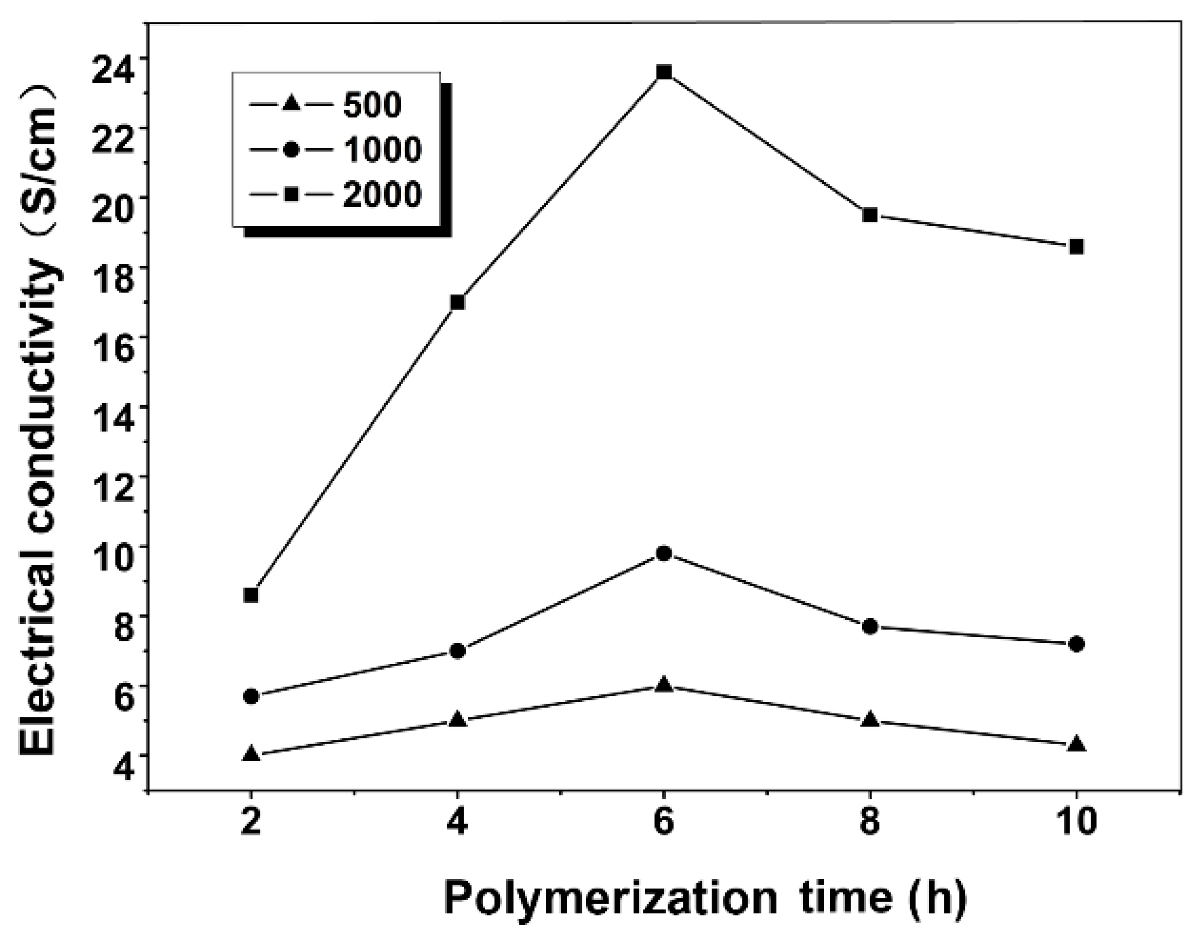
3.7.3. Polymerization Time and Molecular Weight of Grafted Brushes

When polymerization temperature is fixed to 5 °C, and the dopant is added in an amount of 10 wt %, the effects of polymerization time and molecular weight of ASPB brushes on the electrical conductivity are presented in Figure 10. It can be seen from the figure that the electrical conductivity increases with the increase of polymerization time at first; the highest electrical conductivity values are obtained when polymerization time is for 6 h (23.6 S/cm). It may be explained that structural regularity of the conducting polymer will help to improve electrical conductivity. With the extension of polymerization time, the interaction probability between ASPB and PANI increases, thus improving the electrical conductivity. However, a long polymerization time will decrease the electrical conductivity of the conducting polymer, which may be due to the occurrences of side reactions and the local peroxide of the aniline ring [34]. In addition, when other conditions remain the same, different molecular weights of grafted brushes (500 g/mol, 1000 g/mol, 2000 g/mol) are selected to study the relation between it and electrical conductivity. It can be observed from the figure that the increase of the molecular weight of grafted brushes helps to improve the electrical conductivity of nanocomposites. This can be understood by the fact that the long polyelectrolyte chains are favorable to the orderly growth of aniline monomers in the ASPB system, leading to more extended PANI chains with extended conjugate length.
Figure 10. Effects of polymerization time and molecular weight of grafted brushes on the electrical conductivity of PANI/ASPB nanocomposite.
Polymers 07 01473 g010

3.8. Doping Mechanism and Morphological Analysis—SEM Images

In order to explore the doping and conductive mechanism of PANI, the structure of polyaniline is firstly studied.

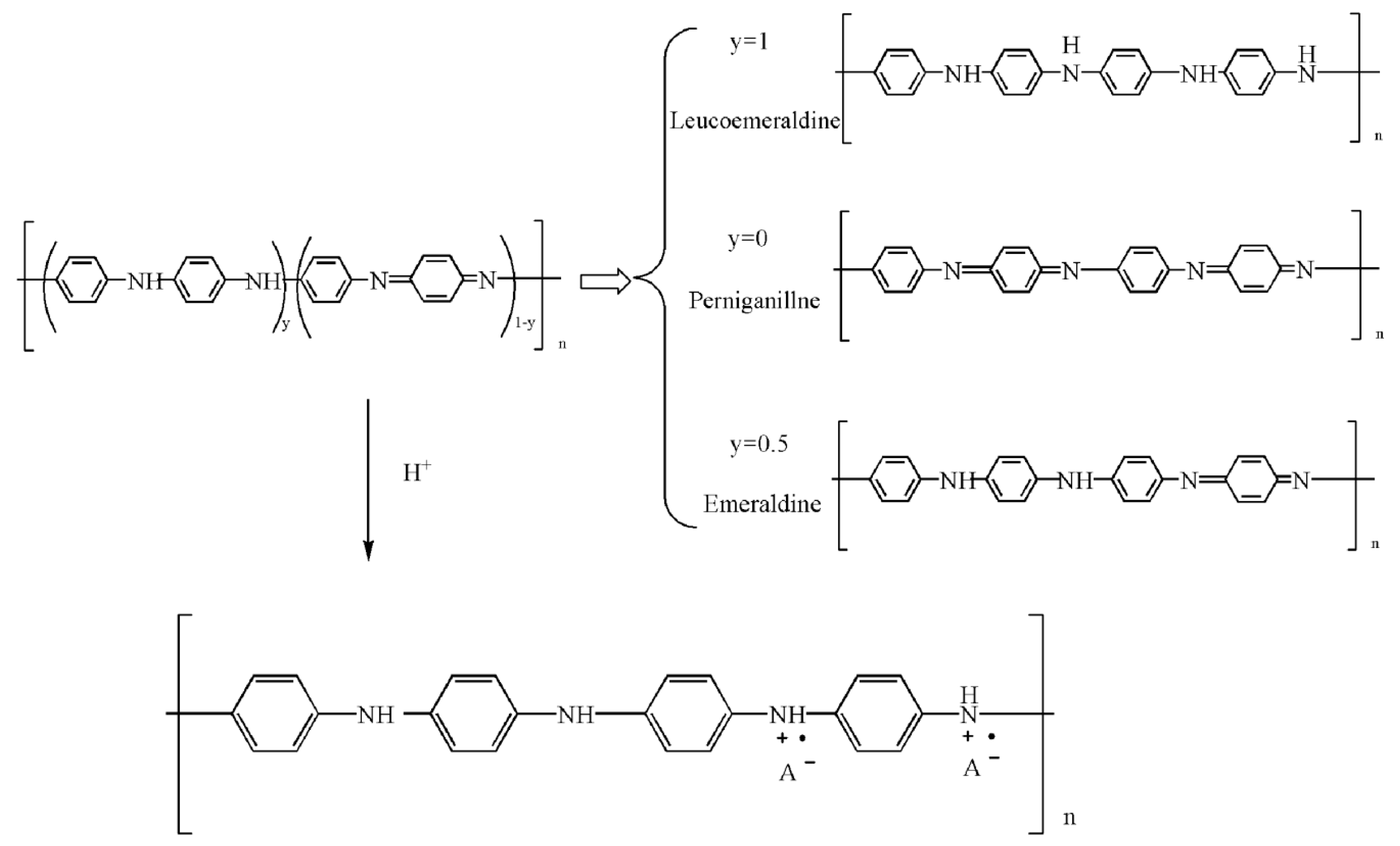
3.8.1. The Structure of Polyaniline

The structure of polyaniline is complex. MacDiarmid [35] presented the benzene-quinone structural model of polyaniline in 1987 (see Figure 11), which was gradually recognized and accepted.
As shown in Figure 11, the structure of PANI changes with different redox status. PANI of reduction state shows a benzene structure (Leucoemeraldine) (y = 1), which is unstable in the environment, and the electrical conductivity of PANI is no more than 10−10 S/cm. PANI of an oxidation state behaves as an alternating “benzene-quinone” structure (Perniganillne) (y = 0 benzene/quinone = 1:1). Since the imino groups in PANI chains cannot be further oxidized, it is stable in the air. Emeraldine structure appears when PANI is in a semi-reduction and semi-oxidation state (y = 0.5, benzene/quinone = 3:1). The best electrical conductivity of PANI at this time is obtained. The redox status of PANI can be transformed by changing the reaction conditions [36].
Figure 11. Scheme representation of redox status for PANI.
Polymers 07 01473 g011
Unlike the doping mechanism of most of the conducting polymers, the dopant itself has no valence change of acid-doped polyaniline. According to the doping mechanism of protonic acid, the doping reaction occurs preferentially in the imine nitrogen atom of polymer chains [37] when a proton acid is added. A protonated imine nitrogen atom forms a radical cation, thus enhancing the electrical conductivity of PANI.
The synthesis process of PANI/ASPB nanocomposite and doping mechanism can be explained by template theory. As described by Figure 12, the electrical conductivity of PANI is mainly dependent on two factors: doping degree (protonation degree) and oxidation degree. The doping degree of PANI can be adjusted by pH. When pH value is kept invariant, the electrical conductivity is determined by the oxidation degree. PANI is insulated from the highest oxidation state and lowest reduction state, the conductive state only appears at semi-oxidation state and semi-reduction state. The conductive and doping mechanisms are explained by the following two aspects.

3.8.2. Three-Dimensional Variable Range Hopping (3D VRH) Theoretical Models

It is known that the electronic structure of PANI doped with protonic acid changes greatly. The conductive mechanism of PANI is usually described by Granular Metal Island Model [38]. The relationship between the electrical conductivity and temperature for doped PANI is according to Equation (4):
σ = σ 0 exp [ ( T 0 T ) 1 r + 1 ]
where σ0 and T0 are constant, which are dependent on the molecular vibration frequency, average transition length, localization length, and state density of materials. r is the dimensions of electronic variable transition. One-dimensional system (r = 1), two-dimensional system (r = 2), and three-dimensional systems (r = 3) are obtained. The Equation (4) also can be transformed to the logarithmic Equation (5):
ln σ = ln σ 0 ( T 0 T ) 1 r + 1
This means there is a linear relationship between lnσ and T−1/2 or T−1/4. That is to say, the conductive mechanism of PANI can be explained by the one-dimensional or the three-dimensional model [39]. Just as shown in SEM images (see Figure 12), PANI/ASPB is composed of similar circular particles with a diameter between 100 and 500 nm, while PANI is fibrous. Based on the three-dimensional variable range-hopping model (3D VRH), it may be assumed that every particle is crimped by a bunch of one-dimensional PANI chains. When the conducting polymer chains are correlated closely, the transition of carrier occurs among the one-dimensional molecular chains, which is three-dimensional variable range-hopping.
Figure 12. Schematic representations of reaction process and doping mechanism of ASPB.
Polymers 07 01473 g012

3.8.3. Template Theory

ASPB serve as a template in the synthesis of PANI/ASPB nanocomposite. The polymerization of aniline monomers takes place in the PSS chains. Compared to the amount of positive charge per unit length in PANI chains, PSS chains contain more negative charge per unit length, thus, part of SO3 is balanced by Na+. The density gradient formed by densely grafted PSS chains affect the distribution of aniline monomers. Thus, the high-concentration aniline monomers are located at the cores of ASPB, where the polymerization reaction happens preferentially. On the basis of the doping mechanism of protonic acid, a polymeric cation is formed by the polymerization of aniline monomers. These polymeric cations, just like multivalent counter-ions in brush layers, make the complexation between PANI and PSS irreversible. As the polymerization of aniline monomers is controlled in the brush layers, ASPB raise the function of the template in synthesis of PANI/ASPB nanocomposite. This is also explored by the SEM study, which enables us to investigate nanoscale morphology of the PANI/ASPB nanocomposite. We can see that a typical “rod-like” or a fibrillar structure of PANI is displayed. The structure of PANI is stretched with length of ca. 600 nm and a diameter of (100 ± 10) nm. While doped with ASPB, a spherical-like structure forms. The space factors for PANI;s orderly growth is provided by ASPB with uniform spherical structure.

4. Conclusions

1. PANI/ASPB nanocomposite has been synthesized by means of chemical oxidative polymerization. Different characterization and analytical methods confirm that ASPB have been doped into PANI system. Different from the “rod-like” or fibrillar morphology of PANI, PANI/ASPB nanocomposite displays a sphere-like structure, suggesting that ASPB serves as a template.
2. PANI/ASPB nanocomposite possesses higher room-temperature electrical conductivity, enhanced thermal stability, and good solubility properties. SiO2 cores are the main factors to improve the thermal stability of conductive nanocomposite, and the PSS chains densely grafted on the surface of the cores play an important role of the increase of solubility properties.
3. The effects of polymerization variables (the types of dopants, polymerization time and temperature, the amount of ASPB, and the molecular weight of grafted polyelectrolyte chains) on the electrical conductivity of nanocomposites are discussed. Results show that the electrical conductivity of PANI/ASPB nanocomposite is 23.6 S/cm at polymerization conditions of polymerization time 6 h, polymerization temperature 5 °C, the amount of ASPB 10%, and the molecular weight of grafted polyelectrolyte chains 2000 g/mol.
4. The conductive mechanism of PANI/ASPB nanocomposite can be explained by the theoretical model of three-dimensional variable range-hopping.

Acknowledgments

This work is supported by Innovation Program of Shanghai Municipal Education Commission (15ZZ112).

Author Contributions

Na Su is responsible for the whole paper, including the designation and performance of experiments, and writing the paper.

Conflicts of Interest

The author declares no conflict of interest.

References

  1. Sangoi, R.; Smith, C.G.; Seymour, M.D.; Venkataraman, J.N.; Clark, D.M.; Kleper, M.L.; Kahn, B.E. Printing radio frequency identification (RFID) tag antennas using inks containing metal nanoparticles. J. Disper. Sci. Technol. 2004, 25, 513. [Google Scholar] [CrossRef]
  2. Huang, Y.; Su, N.; Zhang, X.Z.; Zhao, J.J.; Li, H.B.; Liu, X.H.; Zhang, H.N. Controllable synthesis and characterization of poly(aniline-co-pyrrole) using anionic spherical polyelectrolyte brushes as dopant and template. Polym. Compos. 2014, 5, 1858–1863. [Google Scholar] [CrossRef]
  3. Miles, S.B. RFID Technology and Applications; Cambridge University Press: London, UK, 2011; pp. 6–8. [Google Scholar]
  4. Calvert, P. Inkjet printing for materials and devices. Chem. Mater. 2001, 13, 3299–3305. [Google Scholar] [CrossRef]
  5. Berggren, M.; Nilsson, D.; Robinson, N.D. Organic materials for printed electronics. Nat. Mater. 2007, 6, 3–5. [Google Scholar] [CrossRef] [PubMed]
  6. Zhang, X.; Zhu, J.; Haldolaarachchige, N.; Ryu, J.; Young, D.P.; Wei, S.; Guo, Z. Synthetic process engineered polyaniline nanostructures with tunable morphology and physical properties. Polymer 2012, 53, 2109–2120. [Google Scholar] [CrossRef]
  7. Karwa, A. Printing Studies with Conductive Inks and Exploration of New Conducting Polymer Compositions. Master’s Thesis, Rochester Institute of Technology, Rochester, New York, NY, USA, March 2006. [Google Scholar]
  8. Hara, K.; Kurashige, M.; Ito, S.; Shinpo, A.; Suga, S.; Sayama, K.; Arakawa, H. Novel polyene dyes for highly efficient dye-sensitized solar cells. Chem. Commun. 2003, 252–253. [Google Scholar] [CrossRef]
  9. Shiraknwa, H.; Louis, E.J.; MacDiarmid, A.G.; Chiang, C.K.; Heeger, A.J. Synthesis of electrically conducting organic polymers halogen derivatives of polyacetylene, (CH)x. J. Chem. Soc. Chem. Commun. 1977, 16, 578–580. [Google Scholar] [CrossRef]
  10. Saurin, M.; Armes, S.P. Study of the chemical polymerization of pyrrole onto printed circuit boards for electroplating applications. J. Appl. Polym. Sci. 1995, 56, 41–50. [Google Scholar] [CrossRef]
  11. Wu, J.; Sun, Y.; Xu, W. Investigating thermoelectric properties of doped polyaniline nanowires. Synth. Met. 2014, 189, 177–182. [Google Scholar] [CrossRef]
  12. Wu, J.; Sun, Y.; Pei, W.B.; Huang, L.; Xu, W.; Zhang, Q. Polypyrrole nanotube film for flexible thermoelectric application. Synth. Met. 2014, 196, 173–177. [Google Scholar] [CrossRef]
  13. Zhao, C.; Wu, J.; Kjelleberg, S.; Loo, J.S.C.; Zhang, Q. Employing a flexible and low-cost polypyrrole nanotube membrane as an anode to enhance current generation in microbial fuel cells. Small 2015, 11, 3440–3443. [Google Scholar] [CrossRef] [PubMed]
  14. Gu, H.; Huang, Y.; Zhang, X.; Wang, Q.; Zhu, J.; Shao, L.; Haldolaarachchige, N.; Young, D.P.; Wei, S.; Guo, Z. Magnetoresistive polyaniline-magnetite nanocomposites with negative dielectrical properties. Polymer 2012, 53, 801–809. [Google Scholar] [CrossRef]
  15. Zhou, D.; Li, Y.; Wang, J.; Xu, P.; Han, X. Synthesis of polyaniline nanofibers with high electrical conductivity from CTAB-SDBS mixed surfactants. Mater. Lett. 2011, 65, 3601–3604. [Google Scholar] [CrossRef]
  16. Feng, X.M.; Liu, Y.G.; Lu, C.L.; Zhu, J.-J. One-step synthesis of AgCl/polyaniline core–shell composites with enhanced electroactivity. Nanotechnology 2006, 17, 3578–3583. [Google Scholar] [CrossRef] [PubMed]
  17. Jain, S.; Chakane, S.; Samui, A.B.; Krishnamurthy, V.N.; Bhoraskar, S.V. Humidity sensing with weak acid-doped polyaniline and its composites. Sens. Actuator B Chem. 2003, 96, 124–129. [Google Scholar] [CrossRef]
  18. Shambharkar, B.H.; Umare, S.S. Synthesis and characterization of polyaniline/NiO nanocomposite. J. Appl. Polym. Sci. 2011, 122, 1905–1912. [Google Scholar] [CrossRef]
  19. Vhanakhande, B.B.; Jadhav, S.V.; Kulkarni, D.C.; Puri, V. Investigations on the microwave properties of electropolymerised polyaniline thin film. Microw. Opt. Technol. Lett. 2008, 50, 761–766. [Google Scholar] [CrossRef]
  20. Lin, Q.Q.; Li, Y.; Yang, M.J. Polyaniline nanofiber humidity sensor prepared by electrospinning. Sens. Actuators B Chem. 2012, 161, 967–972. [Google Scholar] [CrossRef]
  21. Su, N.; Gu, P.; Zhao, J.J. Preparation and properties of polyaniline—Anionic sdherical polyelectrolyte brushes (PANI/ASPB) nanocomposites. Micro Nano Lett. 2015, 10, 175–178. [Google Scholar] [CrossRef]
  22. Su, N.; Li, H.B.; Zheng, H.M. Synthesis and characterization of poly(sodium-p-styrene sulfonate)/modified SiO2 spherical brushes. eXPRESS Polym. Lett. 2012, 6, 680–686. [Google Scholar] [CrossRef]
  23. Su, N.; Li, H.B.; Yuan, S.J.; Yi, S.P.; Yin, E.Q. Synthesis and characterization of polypyrrole doped with anionic spherical polyelectrolyte brushes. eXPRESS Polym. Lett. 2012, 6, 697–705. [Google Scholar]
  24. Kulkarni, M.V.; Viswanath, A.K.; Marimuthu, R.; Seth, T. Spectroscopic, transport, and morphological studies of polyaniline doped with inorganic acids. Polym. Eng. Sci. 2004, 44, 1676–1681. [Google Scholar] [CrossRef]
  25. Hatchett, D.W.; Josowicz, M.; Janata, J. Acid doping of polyaniline: Spectroscopic and electrochemical studies. J. Phys. Chem. B 1999, 103, 10992–10998. [Google Scholar] [CrossRef]
  26. Mavundla, S.E.; Malgas, G.F.; Baker, P.; Iwuoha, E.I. Physicochemical and morphological properties of poly(aniline-co-pyrrole). Electroanalysis 2008, 20, 2347–2353. [Google Scholar] [CrossRef]
  27. Kuo, C.-T.; Chen, S.-A.; Hwang, G.-W.; Kuo, H.-H. Field-effect transistor with the water-soluble self-acid-doped polyaniline thin films as semiconductor. Synth. Met. 1998, 93, 155–160. [Google Scholar] [CrossRef]
  28. Souza, F.G.; Soares, B.G. Methodology for determination of PANI. DBSA content in conductive blends by using UV-vis spectrometry. Polym. Test. 2006, 25, 512–517. [Google Scholar] [CrossRef]
  29. Wang, J.; Wang, J.; Yang, Z.; Wang, Z.; Zhang, F.; Wang, S. A novel strategy for the synthesis of polyaniline nanostructures with controlled morphology. React. Funct. Polym. 2008, 68, 1435–1440. [Google Scholar] [CrossRef]
  30. Pouget, J.P.; Jozefowicz, M.E.; Epstein, A.J.; Tang, X.; MacDiarmid, A.G. X-ray structure of polyaniline. Macromolecules 1991, 24, 779–789. [Google Scholar] [CrossRef]
  31. Yin, W.; Ruckenstein, E. Soluble polyaniline co-doped with dodecyl benzene sulfonic acid and hydrochloric acid. Synth. Met. 2000, 108, 39–46. [Google Scholar] [CrossRef]
  32. Maeda, S.; Amres, S.P. Rreparatlon of novel polypyrrole-silica colloidal nanocomposites. J. Colloid Interface Sci. 1993, 159, 257–259. [Google Scholar] [CrossRef]
  33. Hu, X.Q.; Lu, Y.; Liu, J.H. Synthesis of polypyrrole microtubes with actinomorphic morphology in the presence of a beta-cyclodextrin derivative-methyl orange inclusion complex. Macro. Rapid Commun. 2004, 25, 1117–1120. [Google Scholar] [CrossRef]
  34. McManus, P.M.; Yang, S.C.; Cushman, R.J. Elecrtochemical doping of aniline: Eeffest on conductivity and optical spectra. J. Chem. Soc. Chem. Commun. 1985, 22, 1556–1557. [Google Scholar] [CrossRef]
  35. Huang, W.S.; Humphrey, B.D.; MacDiarmid, A.G. Polyaniline, a novel conducting polymer: Morphology and chemistry of its oxidation and reduction in aqueous electrolytes. J. Chem. Soc. 1986, 82, 2385–2400. [Google Scholar] [CrossRef]
  36. Stafström, S.; Brédas, J.L.; Epstein, A.J.; Woo, H.S.; Tanner, D.B.; Huang, W.S.; MacDiarmid, A.G. Polaron lattice in highly conducting polyaniline: Theoretical and optical studies. Phys. Rev. Lett. 1987, 59, 1464–1467. [Google Scholar] [CrossRef] [PubMed]
  37. Castillo-Grtega, M.M.; Inoue, M.B.; Inoue, M.J. Chemical synthesis of highly conducting polyrrole by the use of copper perchlorate as an oxidant. Synth. Met. 1989, 28, 65–70. [Google Scholar] [CrossRef]
  38. Gosh, M.; Barman, A.; Meikap, A.K.; De, S.K.; Chatterjee, S. Hopping transport in HCl doped conducting polyaniline. Phys. Lett. A 1999, 260, 138–148. [Google Scholar]
  39. Jaroslav, S.; Pavel, K.; Aubrey, D.J. The formation of polyaniline and the nature of its structures. Polymer 1996, 37, 367–369. [Google Scholar]

