
Characterization of Ceria Nanoparticles as Abrasives Applied with Defoaming Polymers for CMP (Chemical Mechanical Polishing) Applications

Abstract
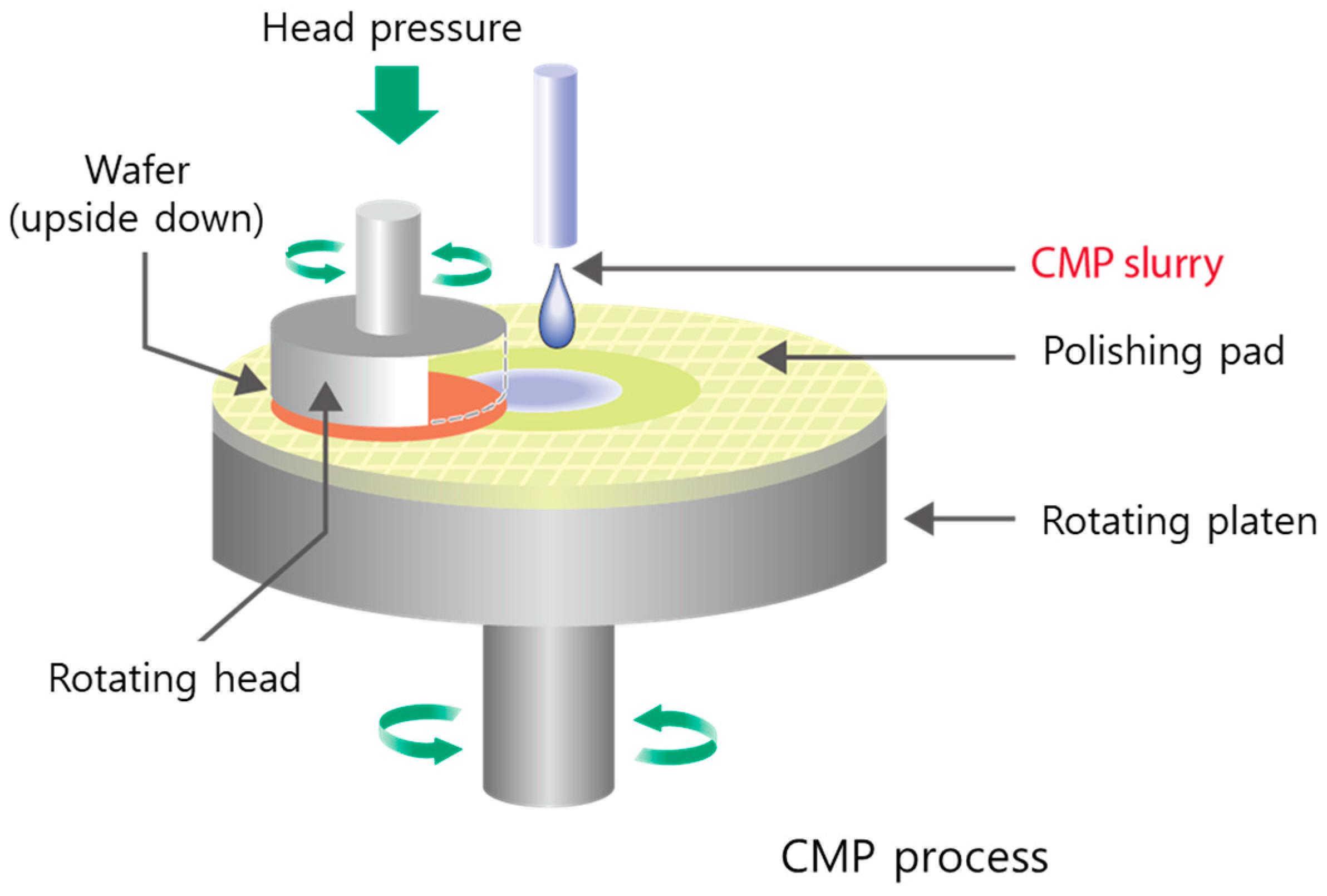
:1. Introduction
2. Experimental Methods
2.1. Preparation of Calcined Ceria Nanoparticles
2.2. Preparation of the Ceria Slurry
2.3. Polishing Experiments
2.4. Characterizations
3. Results and Discussion
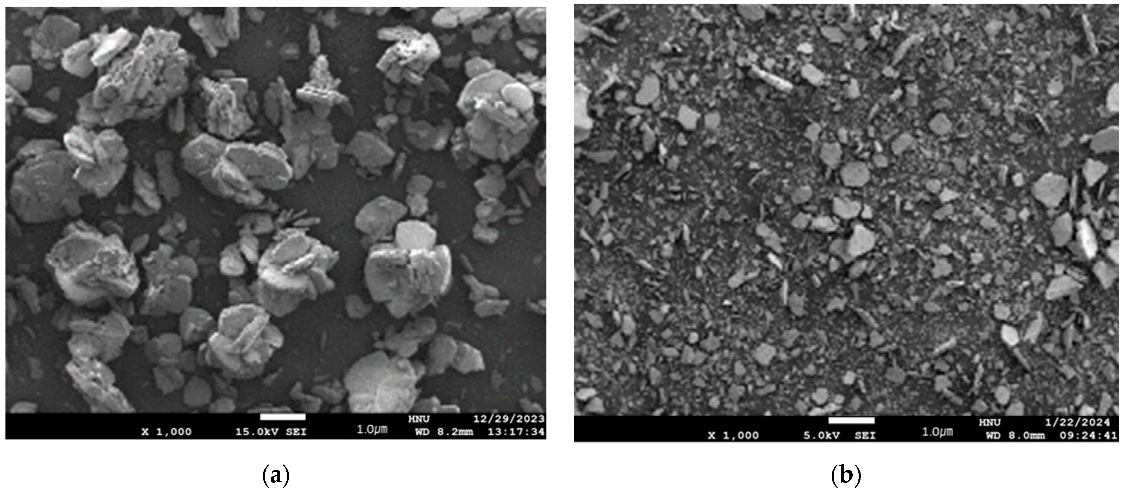
3.1. Preparation of Calcined Ceria Nanoparticles
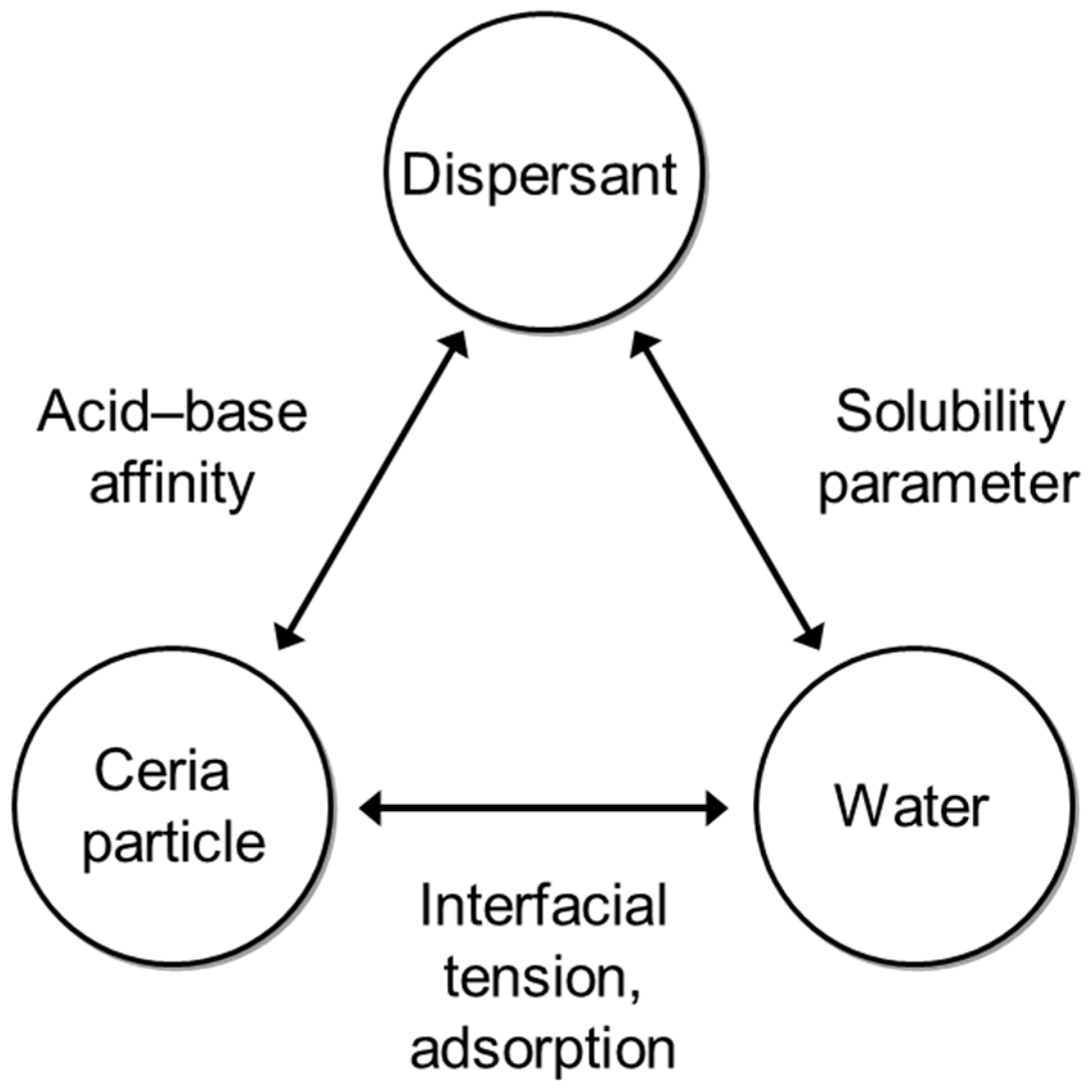
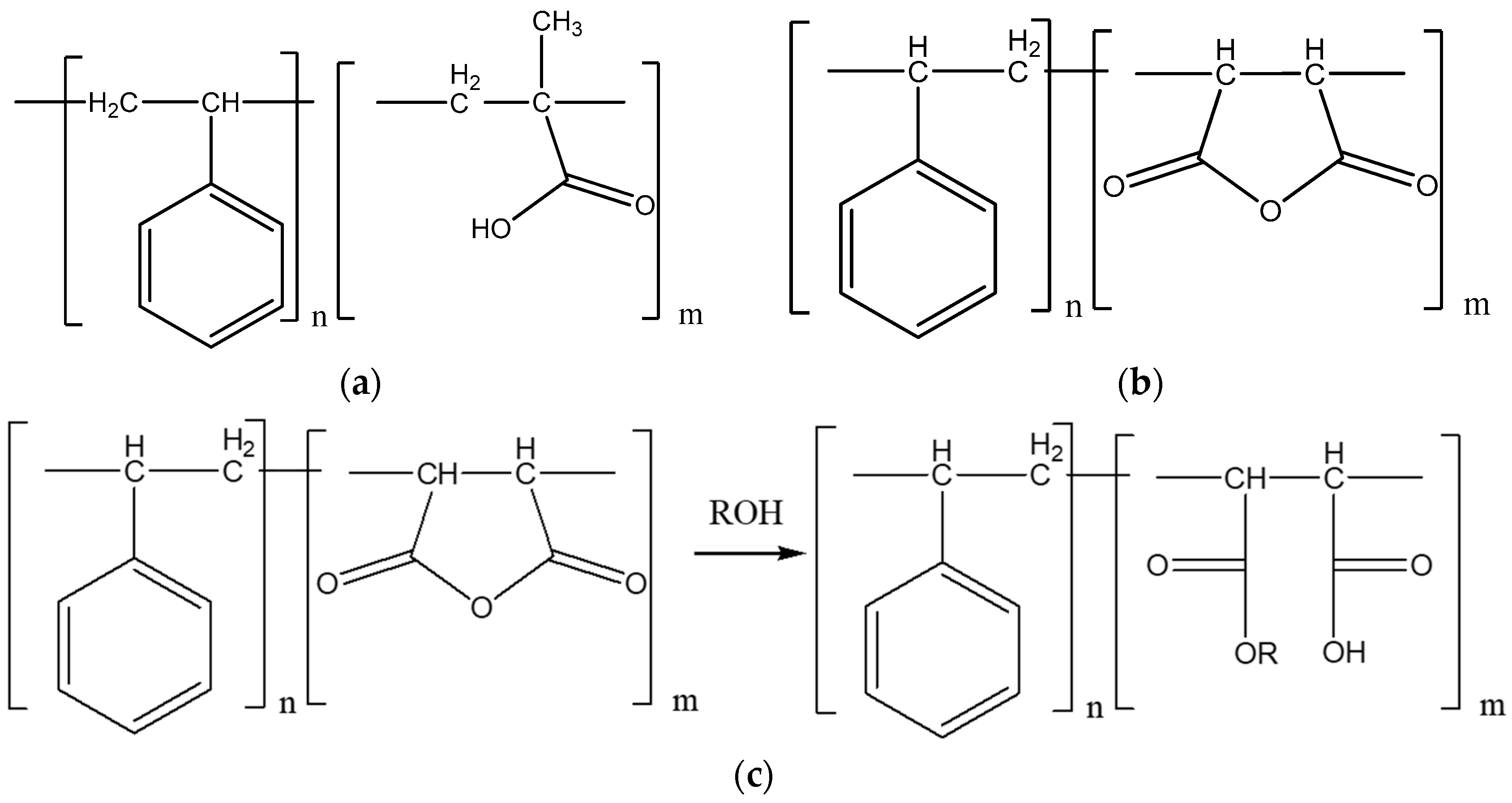
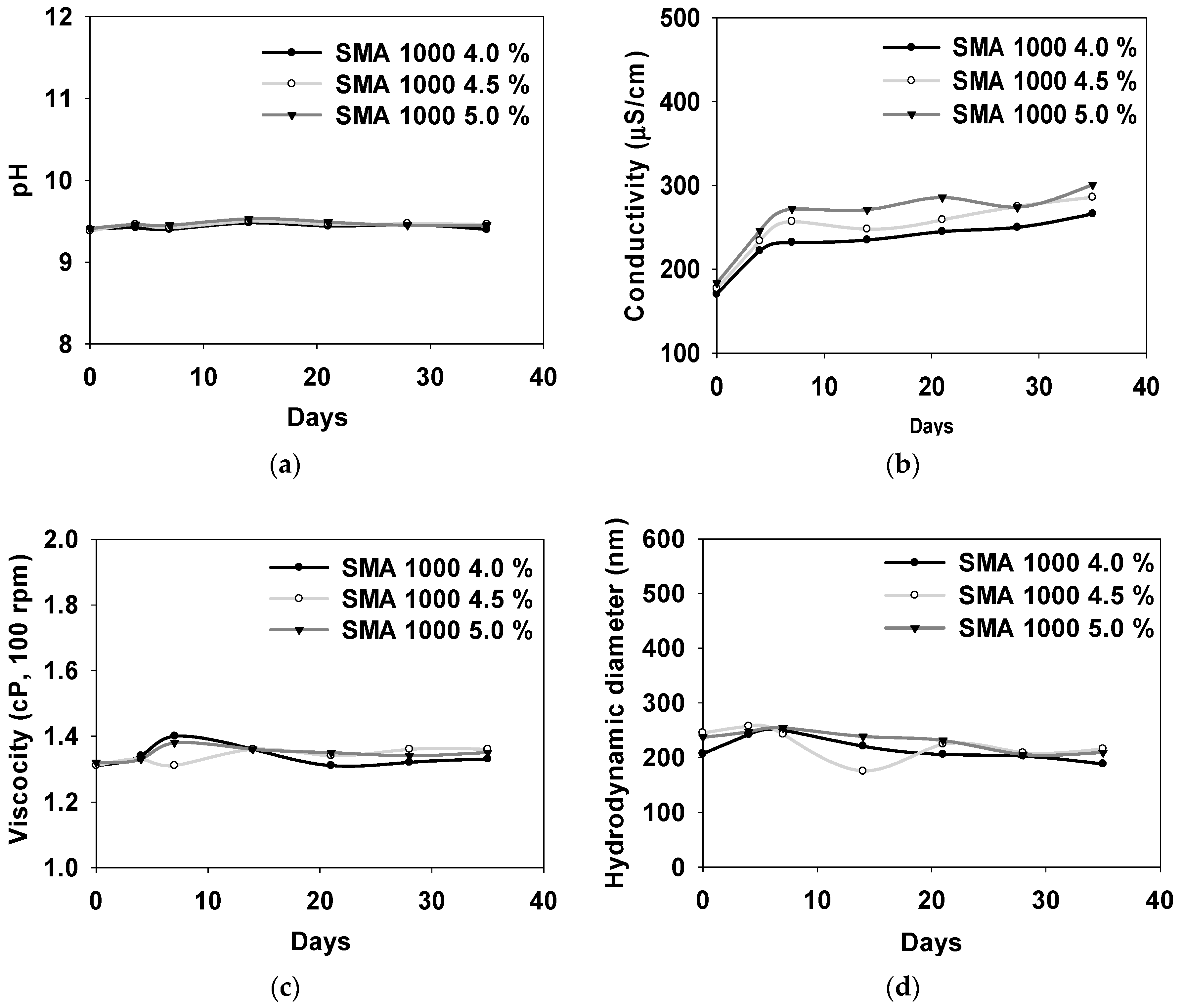
3.2. Properties of Synthesized SMA-1000 Dispersion Material
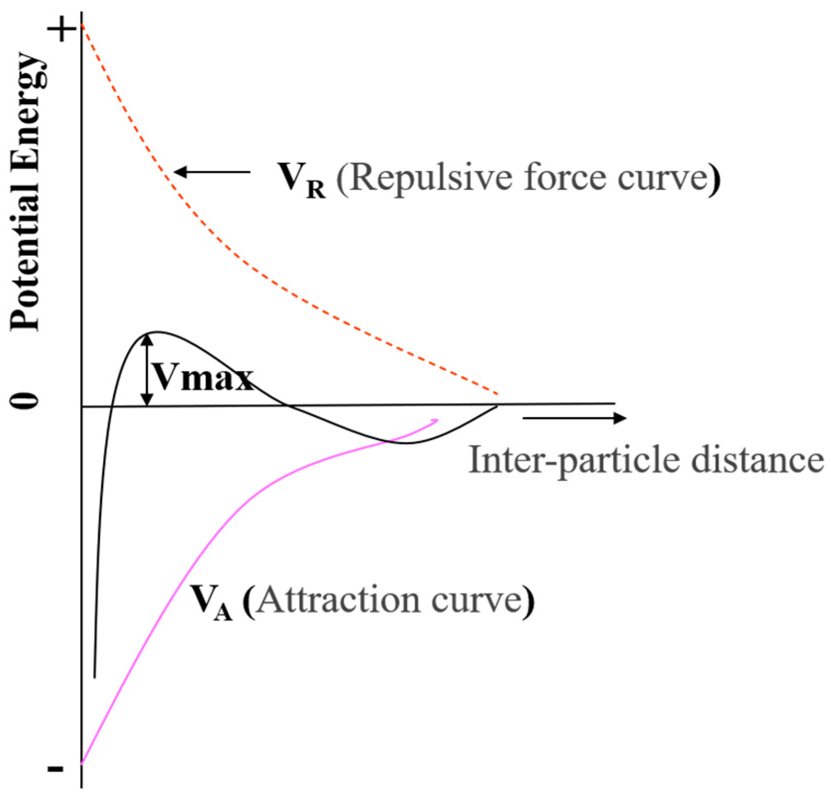
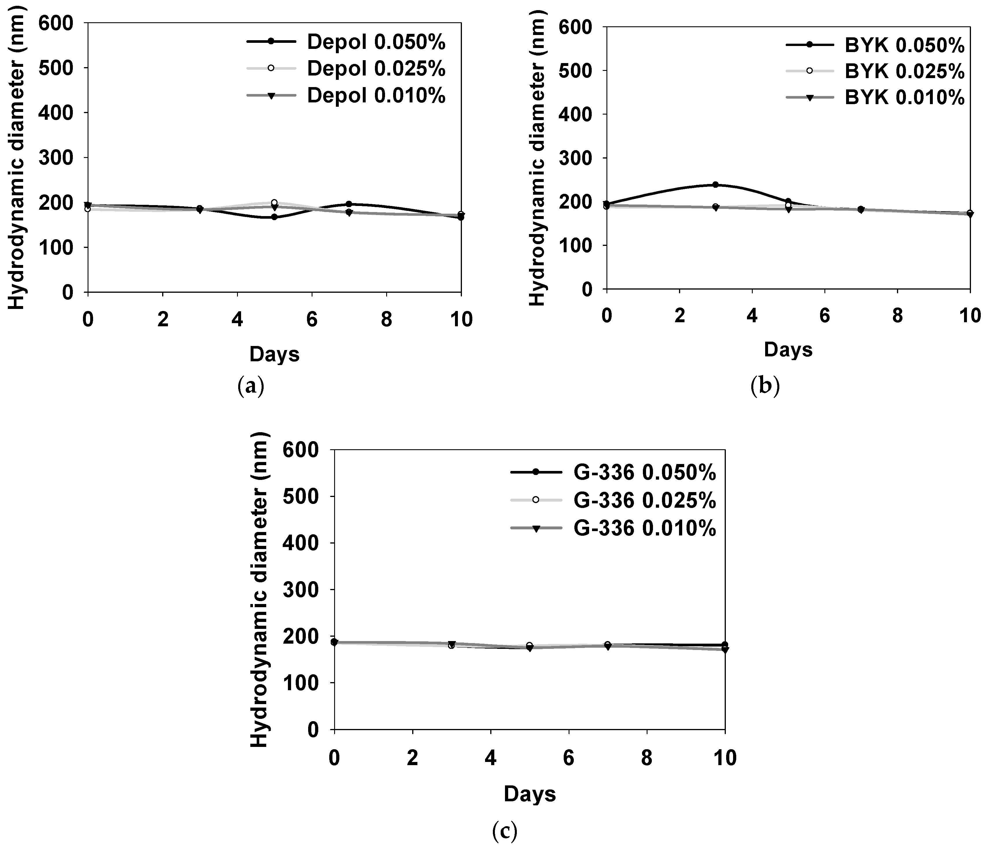
3.3. Properties of SMA-1000 Dispersion Applied with Three Types of Defoaming Polymers as Additives
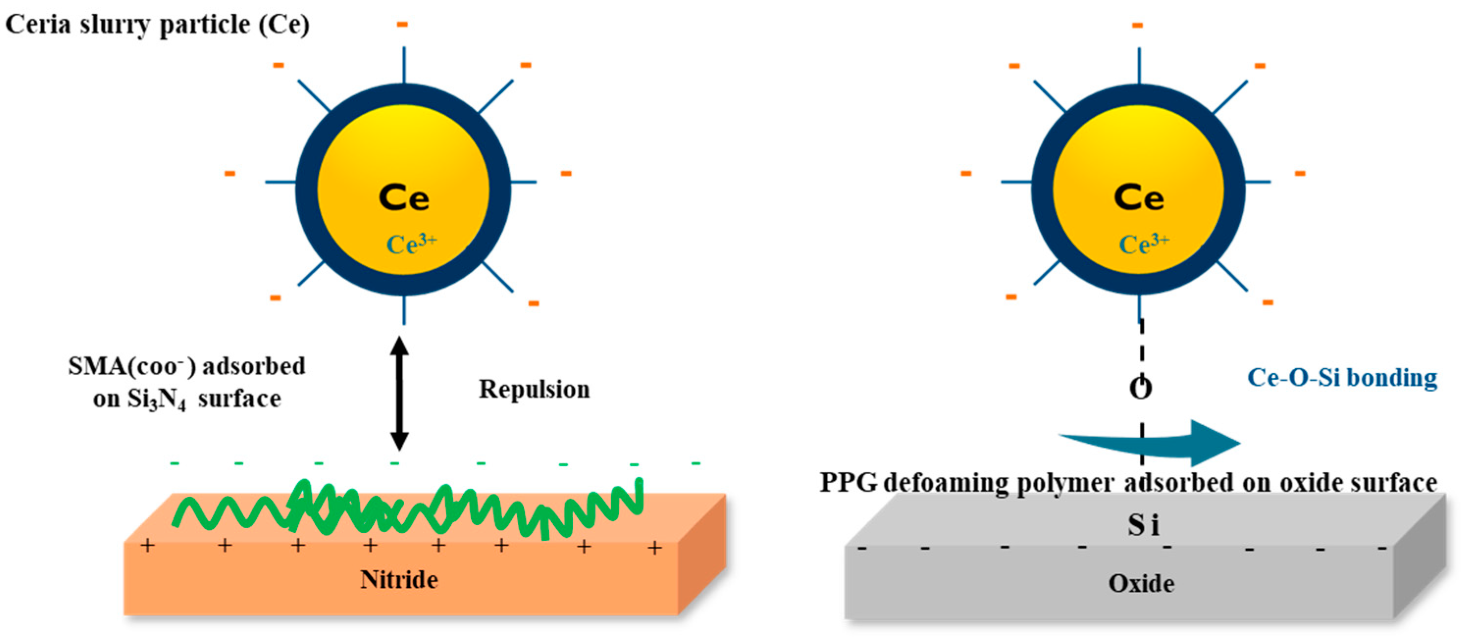
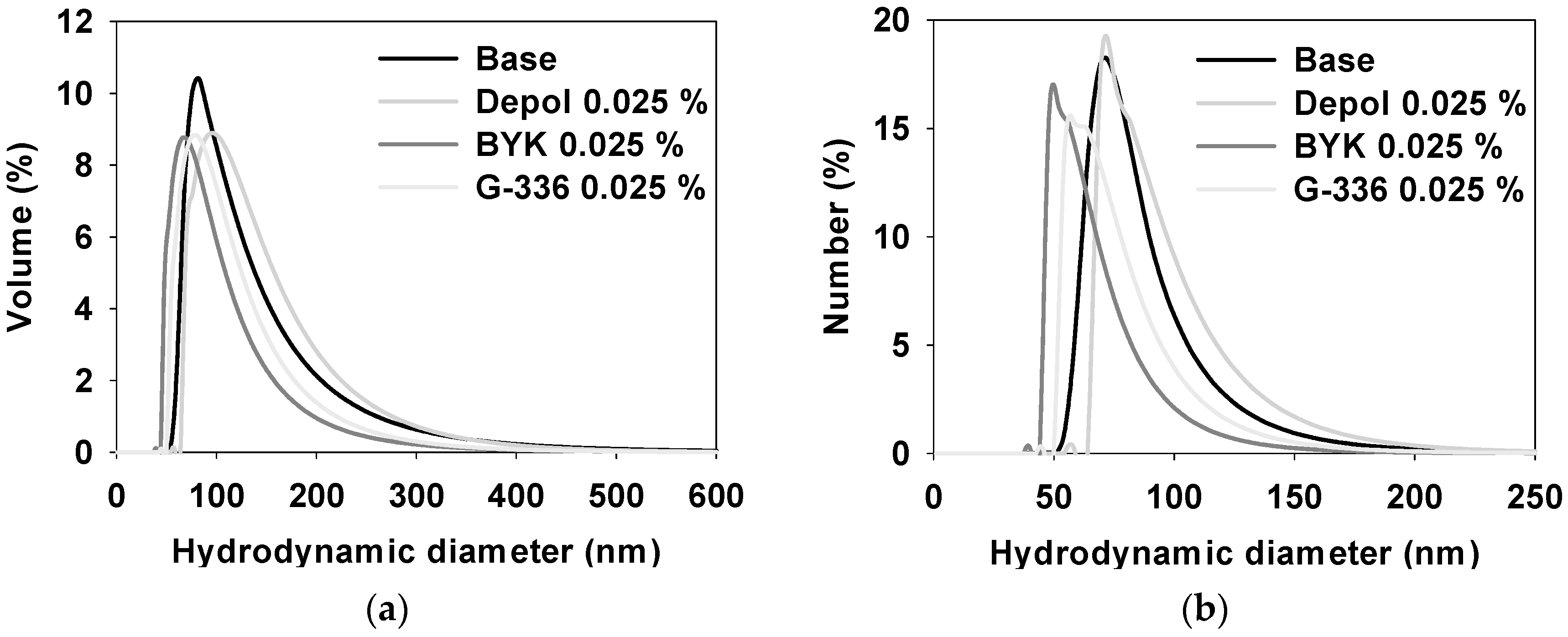
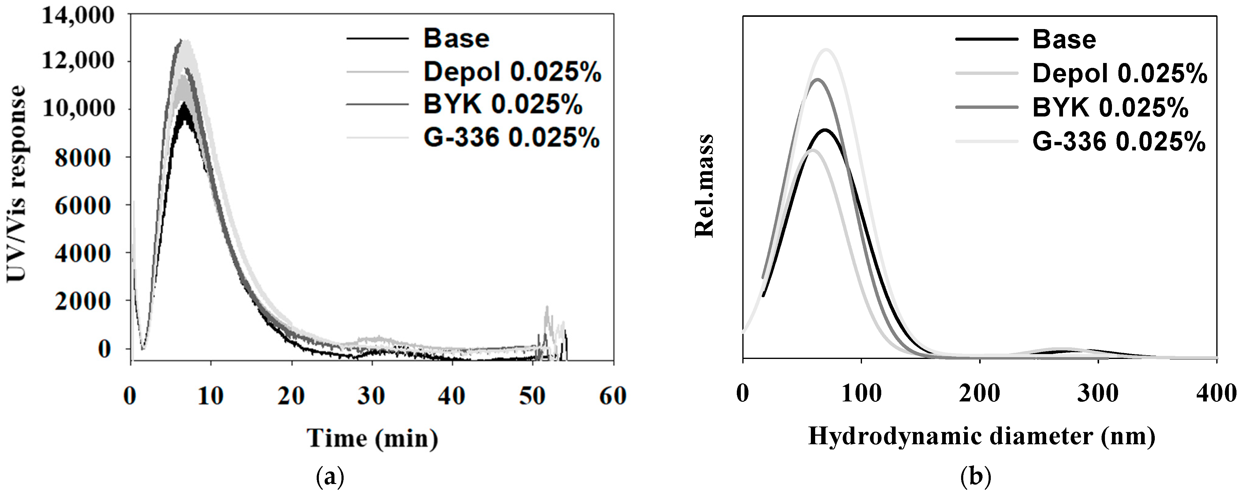
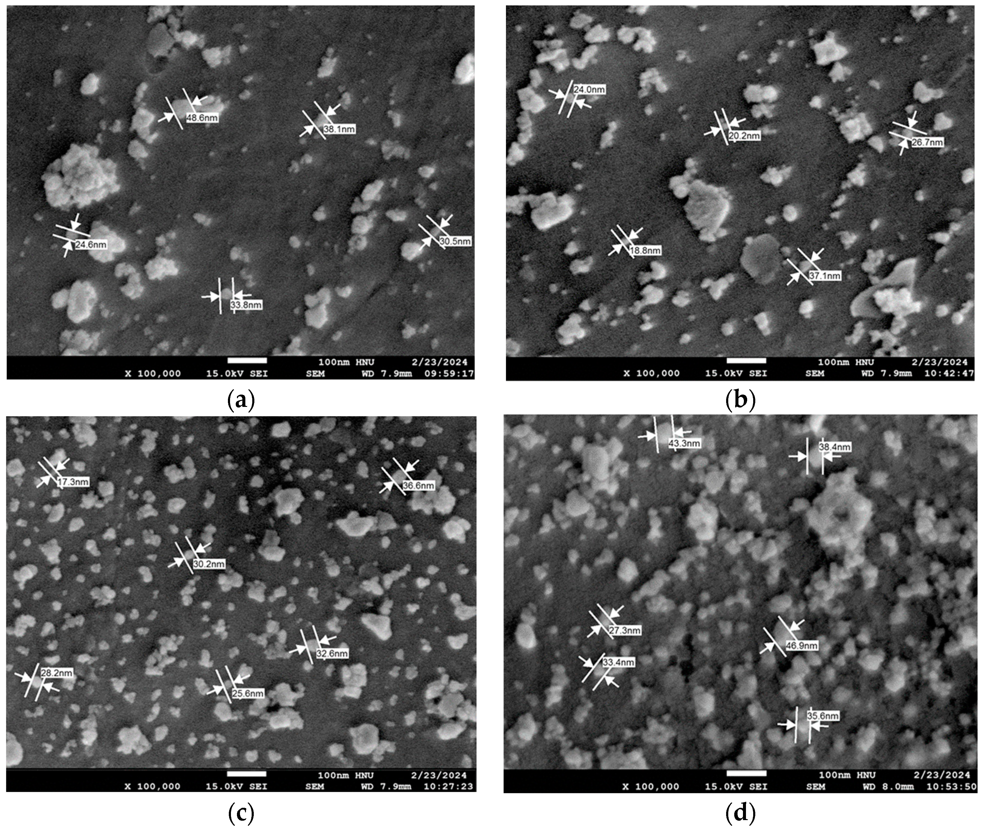
3.4. Properties of Ceria Slurry Applied with Three Types of Defoaming Polymers as Additives
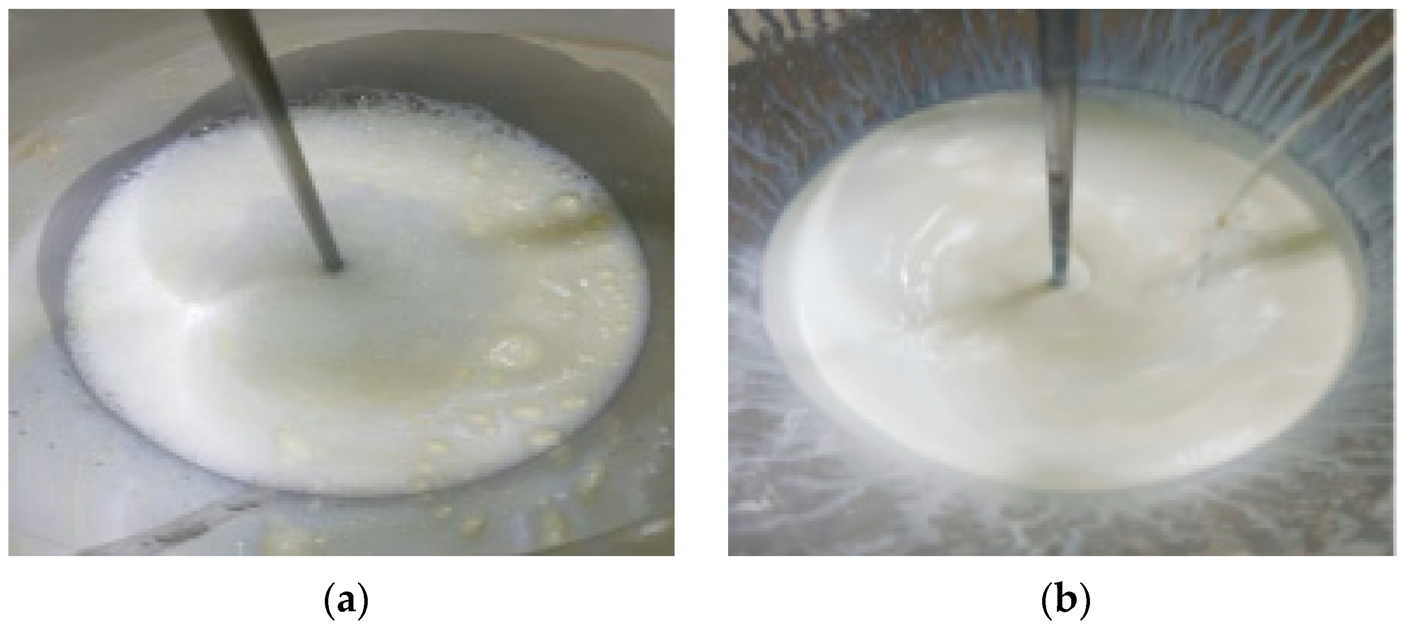
3.5. Polishing Test of Ceria Slurry Applied with Defoaming Polymers as Additives
4. Conclusions
Author Contributions
Funding
Institutional Review Board Statement
Data Availability Statement
Conflicts of Interest
References
- Nanz, G.; Camilletti, L.E. Modeling of chemical-mechanical polishing: A review. Semicond. Manuf. 1995, 8, 382–389. [Google Scholar] [CrossRef]
- Bouzid, D.; Belkhie, N.; Aliouane, T. Optical glass surfaces polishing by cerium oxide particles. IOP Conf. Ser. Mater. Sci. Eng. 2012, 28, 012007. [Google Scholar] [CrossRef]
- Wang, L.; Zhang, K.; Song, Z.; Feng, S. Ceria concentration effect on chemical mechanical polishing of optical glass. Appl. Surf. Sci. 2007, 253, 4951–4954. [Google Scholar] [CrossRef]
- Zhong, Z.W.; Tian, Y.B.; Ng, J.H.; Ang, Y.J. Chemical mechanical polishing (CMP) processes for manufacturing optical silicon substrates with shortened polishing time. Mater. Manuf. Process. 2014, 29, 15–19. [Google Scholar] [CrossRef]
- Cheng, J.; Huang, S.; Li, Y.; Wang, T.; Xie, L.; Lu, X. RE (La, Nd and Yb) doped CeO2 abrasive particles for chemical mechanical polishing of dielectric materials: Experimental and computational analysis. Appl. Surf. Sci. 2020, 506, 144668–144676. [Google Scholar] [CrossRef]
- Oh, S.; Seok, J. An integrated material removal model for silicon dioxide layers in chemical mechanical polishing processes. Wear 2009, 266, 839–849. [Google Scholar] [CrossRef]
- Wang, Y.; Zhao, Y.W.; Chen, X. Chemical mechanical planarization from macroscale to molecular-scale. Mater. Manuf. Process. 2012, 27, 641–649. [Google Scholar] [CrossRef]
- Tian, Y.B.; Ang, Y.J.; Zhong, Z.W.; Xu, H.; Tan, R. Chemical mechanical polishing of glass disk substrates: Preliminary experimental investigation. Mater. Manuf. Process. 2013, 28, 488–494. [Google Scholar] [CrossRef]
- Xu, G.; Zhang, Z.; Meng, F.; Liu, L.; Liu, D.; Shi, C.; Cui, X.; Wang, J.; Wen, W. Atomic-scale surface of fused silica induced by chemical mechanical polishing with controlled size spherical ceria abrasives. J. Manuf. Process. 2023, 85, 783–792. [Google Scholar] [CrossRef]
- Kim, J.Y.; Han, S.J.; Kim, S.S. The Enhanced Electrophoresis Method in Leachate System for Repairing of Leaks in Waste Landfill Geomembrane Liner. J. Korean Soc. Civ. Eng. 2010, 30, 7–15. [Google Scholar]
- Song, G.D.; Kim, M.H.; Lee, Y.T.; Maeng, W.Y. Improvement in the Dispersion Stability of Iron Oxide (Magnetite, Fe3O4) Particles with Polymer Dispersant Injection. Appl. Chem. Eng. 2013, 24, 656–662. [Google Scholar] [CrossRef]
- Lee, S.B.; Park, H.H.; Bae, I.S.; Yoon, J.S.; Kim, B.J. Effect of Al, Al2O3 Dispersants and Heat Treatment on Deposits from Watt’s Ni Plating Bamth. Korean J. Mater. Res. 2002, 12, 153–159. [Google Scholar]
- Hedrick, J.B.; Sinha, S.P. Cerium-based polishing compounds: Discovery to manufacture. J. Alloys Compd. 1994, 207–208, 377–382. [Google Scholar] [CrossRef]
- Urie, R.W.; Wylie, A.W. Rare earth oxides for glass polishing. J. Soc. Chem. Ind. 1947, 66, 433–436. [Google Scholar] [CrossRef]
- Kosynkin, V.D.; Arzgatkina, A.A.; Ivanov, E.N.; Chtoutsa, M.G.; Grabko, A.I.; Kardapolov, A.V. The study of process production of polishing powder based on cerium dioxide. J. Alloys Compd. 2000, 303–304, 421–425. [Google Scholar] [CrossRef]
- Kim, D.-H.; Kim, S.-K.; Kang, H.-G.; Park, J.-G.; Paik, U. The effect of cerium precursor agglomeration on the synthesis of ceria particles and its influence on shallow trench isolation chemical mechanical polishing performance. Jpn. J. Appl. Phys. 2005, 44, 8422–8426. [Google Scholar] [CrossRef]
- Li, Y.; Cheng, C.; Chen, W.; Hu, J.; Zhou, X.; Hu, P. Preparation and polishing property of ultra-fine ceria by calcining hydrate cerium acetate directly. Chin. J. Inorg. Chem. 2006, 22, 733–737. [Google Scholar]
- Kurokawa, S.; Toyama, T.; Hayashi, T.; Suda, E.; Tokuda, J. Controllable CMP of oxide flim by using colloidal ceria slurry. In Proceedings of the ICPT 2017—International Conference on Planarization/CMP Technology, Leuven, Belgium, 11–13 October 2017; pp. 177–182. [Google Scholar]
- Kim, N.Y.; Kim, G.; Sun, H.; Hwang, U.; Kim, J.; Kwak, D.; Park, I.-K.; Kim, T.; Suhr, J.; Nam, J.-D. A nanoclustered ceria abrasives with low crystallinity and high Ce3+/Ce4+ ratio for scratch reduction and high oxide removal rates in the chemical mechanical planarization. J. Mater. Sci. 2022, 57, 12318–12328. [Google Scholar] [CrossRef]
- Kim, E.; Hong, J.; Seok, H.; Kim, T. Photo oxidative degradation of polyacids derived ceria nanoparticle modulation for chemical mechanical polishing. Sci. Rep. 2022, 12, 1613. [Google Scholar] [CrossRef]
- Sahir, S.; Yerribonia, N.P.; Han, S.Y.; Han, K.M.; Kim, T.G.; Mahadev, N.; Park, J.G. Investigation of the effect of different cleaning forces on Ce-O-Si bonding during oxide post-CMP cleaning. Appl. Surf. Sci. 2021, 545, 149035–149046. [Google Scholar] [CrossRef]
- Myong, K.K.; Byun, J.; Choo, M.J.; Kim, H.; Kim, J.; Lim, Y.T.; Kim, J.J. Direct and quantitative study of ceria–SiO2 interaction depending on Ce3+ concentration for chemical mechanical planarization (CMP) cleaning. Mater. Sci. Semicond. Process. 2021, 122, 105500–105506. [Google Scholar] [CrossRef]
- Kim, K.; Yi, D.K.; Paik, U. Increase in Ce3+ concentration of ceria nanoparticles for high removal rate of SiO2 in chemical mechanical planarization. ECS J. Solid State Sci. Technol. 2017, 6, 681–685. [Google Scholar] [CrossRef]
- Netzband, C.M.; Dunn, K. Investigation into the effect of CMP slurry chemicals on ceria abrasive oxidation state using XPS. ECS J. Solid State Sci. Technol. 2019, 8, 629–633. [Google Scholar] [CrossRef]
- Lin, S.-S. Preparing an active cerium oxide catalyst for the catalytic incineration of aromatic hydrocarbons. Appl. Catal. 2004, 268, 227–233. [Google Scholar]
- He, H.-W.; Wu, X.-Q.; Ren, W.; Peng, S.; Xi, Y.; Zhi, S.T. Synthesis of crystalline cerium dioxide hydrosol by a sol–gel method. Ceram. Int. 2012, 38, S501–S504. [Google Scholar] [CrossRef]
- Chen, H.I.; Chang, H.-Y. Synthesis of nanocrystalline cerium oxide particles by the precipitation method. Ceram. Int. 2005, 31, 795–802. [Google Scholar] [CrossRef]
- Rojas, S.; Gispert, J.D.; Abad, S.; Buaki-Sogo, M.; Victor, V.M. In Vivo biodistribution of amino-functionalized ceria nanoparticles in rats using positron emission tomography. Mol. Pharm. 2012, 9, 3543–3550. [Google Scholar] [CrossRef]
- Annis, J.W.; Fisher, J.M.; Thompsett, D.; Walton, R.I. Solvothermal synthesis routes to substituted cerium dioxide materials. Inorganics 2021, 9, 40. [Google Scholar] [CrossRef]
- Ali, M.M.; Mahdi, H.S.; Parveen, A. Optical properties of cerium oxide (CeO2) nanoparticles synthesized by hydroxide mediated method. AIP Conf. Proc. 2018, 1953, 030044. [Google Scholar]
- Wakamatsu, K.; Kurokawa, S.; Toyama, T.; Hayashi, T. CMP characteristics of quarts glass substrate by aggregated colloidal ceria slurry. Precis. Eng. 2019, 60, 458–464. [Google Scholar] [CrossRef]
- Lyklema, J.; van Leeuwen, H.P.; Minor, M. DLVO-theory, a dynamic re-interpretation. Adv. Colloid Interface Sci. 1999, 83, 33–69. [Google Scholar] [CrossRef]
- Kabir, H.; Garg, N. Rapid prediction of cementitious initial sorptivity via surface wettability. NPJ Mater. Degrad. 2023, 7, 52. [Google Scholar] [CrossRef]
- Deltombe, R.; Kubiak, K.J.; Bigerelle, M. How to Select the Most Relevant 3D Roughness Parameters of a Surface. Scanning 2014, 36, 150–160. [Google Scholar] [CrossRef]
- Seo, J.; Lee, J.W.; Moon, J.; Sigmund, W.; Paik, U. Role of the surface chemistry of ceria surfaces on silicate adsorption. ACS Appl. Mater. Interfaces 2014, 6, 7388. [Google Scholar] [CrossRef] [PubMed]
- Kim, S.K.; Lee, S.; Paik, U.; Katoh, T.; Park, J.G. Influence of the electrokinetic behaviors of abrasive ceria particles and the deposited plasma-enhanced tetraethylorthosilicate and chemically vapor deposited Si3N4 films in an aqueous medium on chemical mechanical planarization for shallow trench isolation. J. Mater. Res. 2003, 18, 2163. [Google Scholar]
- Hackley, V.A. Colloidal processing of silicon nitride with poly (acrylic acid): I, adsorption and electrostatic interactions. J. Am. Ceram. Soc. 1997, 80, 2315. [Google Scholar] [CrossRef]
- Sehgal, A.; Lalatonne, Y.; Berret, J.-F.; Morvan, M. Precipitation−redispersion of cerium oxide nanoparticles with poly(acrylic acid): Toward stable dispersions. Langmuir 2005, 21, 9359. [Google Scholar] [CrossRef] [PubMed]
- Lee, J.; Bae, J.; Kim, W.; Lee, S. A Study on Aqueous Dispersing of Carbon Black Nanoparticles Surface-Coated with Styrene Maleic Acid (SMA) Copolymer. Polymers 2022, 14, 5455. [Google Scholar] [CrossRef]


| Element | Cerium Carbonate | Cerium Oxide | ||
|---|---|---|---|---|
| wt% | Atomic % | wt% | Atomic % | |
| C | 10.8 | 25.2 | 5.46 | 20.2 |
| O | 36.8 | 64.3 | 20.2 | 56.2 |
| Ce | 52.4 | 10.5 | 74.3 | 23.5 |
| Name | pH | Mw |
|---|---|---|
| SMA 1000 | 8.07 | 8.60 × 10⁴ |
| Conc. (%) | pH | Conductivity (ms/cm) | Viscosity (cP) | DLS (nm) |
|---|---|---|---|---|
| 4.0 | 9.43 ± 0.0300 | 231 ± 30.5 | 1.34 ± 0.0300 | 216 ± 22.3 |
| 4.5 | 9.45 ± 0.0400 | 248 ± 35.6 | 1.34 ± 0.0200 | 224 ± 27.6 |
| 5.0 | 9.46 ± 0.0400 | 262 ± 38.2 | 1.35 ± 0.0200 | 232 ± 18.3 |
| Defoaming Polymer | Conc (%) | pH | Conductivity (μs/cm) | Viscosity (cP) | DLS (nm) |
|---|---|---|---|---|---|
| Depol | 0.010 | 9.68 ± 0.0500 | 205 ± 10.9 | 1.33 ± 0.0100 | 183 ± 9.16 |
| 0.025 | 9.68 ± 0.0600 | 208 ± 13.0 | 1.32 ± 0.0100 | 183 ± 9.82 | |
| 0.050 | 9.67 ± 0.0500 | 209 ± 14.9 | 1.32 ± 0.0100 | 181 ± 4.28 | |
| BYK | 0.010 | 9.68 ± 0.0500 | 206 ± 11.1 | 1.32 ± 0.0100 | 183 ± 7.77 |
| 0.025 | 9.68 ± 0.0600 | 209 ± 11.2 | 1.31 ± 0.0100 | 184 ± 7.40 | |
| 0.050 | 9.68 ± 0.0600 | 212 ± 15.0 | 1.31 ± 0.0100 | 197 ± 4.80 | |
| G-336 | 0.010 | 9.64 ± 0.0200 | 218 ± 9.07 | 1.32 ± 0.0100 | 179 ± 6.43 |
| 0.025 | 9.65 ± 0.0300 | 219 ± 8.93 | 1.32 ± 0.0100 | 179 ± 4.75 | |
| 0.050 | 9.66 ± 0.0300 | 245 ± 11.6 | 1.32 ± 0.0100 | 180 ± 4.32 |
| Size Distribution (nm) | Base | Depol | BYK | G-336 |
|---|---|---|---|---|
| Volume | 117 ± 60.8 | 128 ± 57.1 | 91.4 ± 45.6 | 103 ± 47.9 |
| Number | 83.2 ± 23.2 | 92.6 ± 26.0 | 64.8 ± 18.5 | 74.3 ± 21.1 |
| Size Distribution (nm) | Base | Depol | BYK | G-336 |
|---|---|---|---|---|
| Main | 72.2 ± 1.34 | 62.6 ± 3.20 | 73.3 ± 1.39 | 82.0 ± 7.69 |
| Minor | 283 ± 3.01 | 293 ± 1.52 | N.D | N.D |
| Polishing Rate (Å/min) | Base | Depol | BYK | G-336 |
|---|---|---|---|---|
| PETEOS | 3493 | 4650 | 5558 | 5417 |
| Nitride | 60 | 75 | 83 | 68 |
| Selection ratio | 59 | 62 | 67 | 80 |
Disclaimer/Publisher’s Note: The statements, opinions and data contained in all publications are solely those of the individual author(s) and contributor(s) and not of MDPI and/or the editor(s). MDPI and/or the editor(s) disclaim responsibility for any injury to people or property resulting from any ideas, methods, instructions or products referred to in the content. |
© 2024 by the authors. Licensee MDPI, Basel, Switzerland. This article is an open access article distributed under the terms and conditions of the Creative Commons Attribution (CC BY) license (https://creativecommons.org/licenses/by/4.0/).
Share and Cite
Hwang, S.; Kim, W. Characterization of Ceria Nanoparticles as Abrasives Applied with Defoaming Polymers for CMP (Chemical Mechanical Polishing) Applications. Polymers 2024, 16, 844. https://doi.org/10.3390/polym16060844
Hwang S, Kim W. Characterization of Ceria Nanoparticles as Abrasives Applied with Defoaming Polymers for CMP (Chemical Mechanical Polishing) Applications. Polymers. 2024; 16(6):844. https://doi.org/10.3390/polym16060844
Chicago/Turabian StyleHwang, Sohee, and Woonjung Kim. 2024. "Characterization of Ceria Nanoparticles as Abrasives Applied with Defoaming Polymers for CMP (Chemical Mechanical Polishing) Applications" Polymers 16, no. 6: 844. https://doi.org/10.3390/polym16060844