
Press Conduction Welding for Secondary Bonding of Aircraft Skin/Stiffener Assemblies Using Carbon Fiber/PEKK Thermoplastic Composites and PEI Adhesive


Abstract
:1. Introduction
2. Investigation of Welding Temperature Range Based on Single-Lap Shear Tests
2.1. Materials
2.2. Single-Lap Shear Test
2.3. Press Consolidation Welding of Skin and Omega Stiffener
3. Results
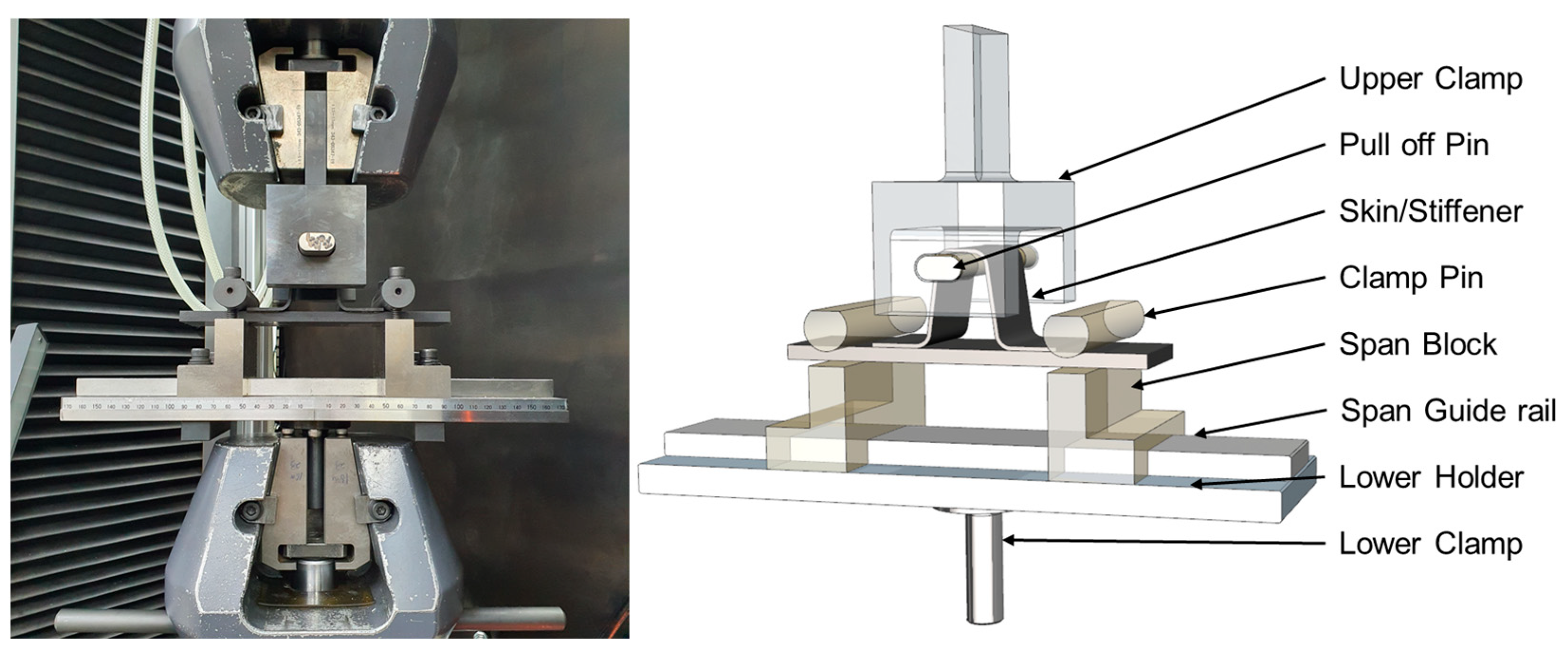
3.1. Pull-Off Test
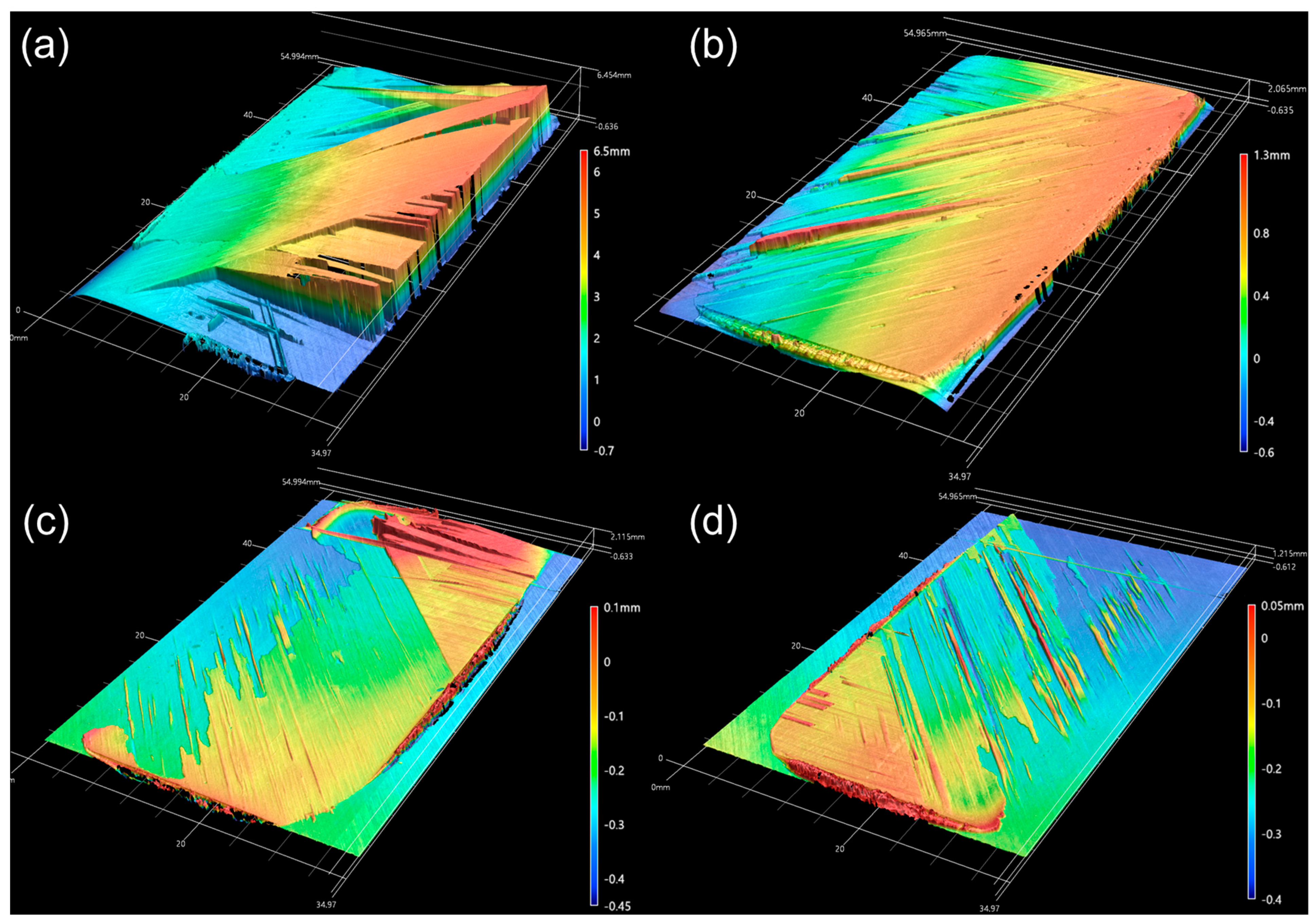
3.2. Fracture Surface Analysis
4. Discussion
5. Conclusions
- (1)
- The temperature range for the process was determined using DSC. The optimal conditions were then determined by performing a single-lap shear test. The results indicated that the highest bonding strength of approximately 19.5 MPa was achieved at a temperature of 340 °C. Conversely, no bonding was observed under conditions close to the crystallization temperature of PEKK. It is believed that this was due to insufficient melting of the PEI adhesive, which resulted in a lack of interdiffusion.
- (2)
- Various types of composite failures, including fiber tear failure, were observed under the bonding conditions derived from the single-lap shear test, aligning with the findings from the pull-off tests of the skin/omega stiffener specimens.
- (3)
- It is believed that the squeezed PEI adhesive lump causes the following effect. The formation of irregular lumps leads to the growth of cracks inside the laminate, which results in fiber tear failure and bridging of specific plies during the fracture process. As a result, it is assumed that there is a phenomenon where the maximum load and the first peak load do not match in the pull-off test results.
- (4)
- The welding of thermoplastic composites typically excludes the use of adhesives owing to the reversible reaction characteristics of the matrix. However, this investigation aimed to analyze experimentally and highlight the challenges that must be addressed in the application of secondary bonding to thermoplastic composites. Based on this analysis, the study contributes to a deeper understanding of the mechanical behavior of bonded joints in thermoplastic composite structures and underscores the need for further research to refine bonding processes in aerospace applications. In order to minimize the influence of adhesive lump, it is necessary to conduct in-depth research on fatigue strength and physical properties after bonding through a peel strength-based double cantilever beam test and end-notch flexure test. Such research is being planned.
Author Contributions
Funding
Institutional Review Board Statement
Data Availability Statement
Conflicts of Interest
References
- Soutis, C. Fibre reinforced composites in aircraft construction. Prog. Aerosp. Sci. 2005, 41, 143–151. [Google Scholar] [CrossRef]
- Roberts, T. Rapid growth forecast for carbon fibre market. Reinf. Plast. 2007, 51, 10–13. [Google Scholar] [CrossRef]
- Heimbs, S.; Heller, S.; Middendorf, P.; Hähnel, F.; Weiße, J. Low velocity impact on CFRP plates with compressive preload: Test and modelling. Int. J. Impact Eng. 2009, 36, 1182–1193. [Google Scholar] [CrossRef]
- Cantwell, W.J.; Morton, J. Comparison of the low and high velocity impact response of CFRP. Composites 1989, 20, 545–551. [Google Scholar] [CrossRef]
- Abrate, S. Impact on laminated composite materials. Appl. Mech. Rev. 1991, 44, 155–190. [Google Scholar] [CrossRef]
- Blundell, D.J.; Crick, R.A.; Fife, B.; Peacock, J.; Keller, A.; Waddon, A. Spherulitic morphology of the matrix of thermoplastic PEEK/Carbon fibre aromatic polymer composites. J. Mater. Sci. 1989, 24, 2057–2064. [Google Scholar] [CrossRef]
- Vu-Khanh, T.; Denault, J. Effect of molding parameters on the interfacial strength in PEEK/Carbon composites. J. Reinf. Plast. Compos. 1993, 12, 916–931. [Google Scholar] [CrossRef]
- Choupin, T.; Fayolle, B.; Régnier, G.; Paris, C.; Cinquin, J.; Brulé, B. Isothermal crystallization kinetic modeling of Poly(Etherketoneketone) (PEKK) copolymer. Polymer 2017, 111, 73–82. [Google Scholar] [CrossRef]
- Ageorges, C.; Ye, L. Fusion Bonding of Polymer Composites; Springer: London, UK, 2002; ISBN 978-1-4471-1087-3. [Google Scholar]
- Ageorges, C.; Ye, L.; Hou, M. Experimental investigation of the resistance welding for thermoplastic-matrix composites. Part I: Heating element and heat transfer. Compos. Sci. Technol. 2000, 60, 1027–1039. [Google Scholar] [CrossRef]
- Hou, M.; Ye, L.; Mai, Y.-W. An experimental study of resistance welding of carbon fibre fabric reinforced polyetherimide (CF Fabric/PEI) composite material. Appl. Compos. Mater. 1999, 6, 35–49. [Google Scholar] [CrossRef]
- Koutras, N.; Villegas, I.F.; Benedictus, R. Influence of temperature on the strength of resistance welded glass fibre reinforced PPS joints. Compos. Part A Appl. Sci. Manuf. 2018, 105, 57–67. [Google Scholar] [CrossRef]
- Dubé, M.; Hubert, P.; Gallet, J.N.A.H.; Stavrov, D.; Bersee, H.E.N.; Yousefpour, A. Metal mesh heating element size effect in resistance welding of thermoplastic composites. J. Compos. Mater. 2012, 46, 911–919. [Google Scholar] [CrossRef]
- Hou, M.; Yang, M.; Beehag, A.; Mai, Y.-W.; Ye, L. Resistance welding of carbon fibre reinforced thermoplastic composite using alternative heating element. Compos. Struct. 1999, 47, 667–672. [Google Scholar] [CrossRef]
- Russello, M.; Catalanotti, G.; Hawkins, S.C.; Falzon, B.G. Welding of thermoplastics by means of carbon-nanotube Web. Compos. Commun. 2020, 17, 56–60. [Google Scholar] [CrossRef]
- Russello, M.; Catalanotti, G.; Hawkins, S.C.; Falzon, B.G. Resistance welding of carbon fibre reinforced PEKK by means of CNT webs. J. Compos. Mater. 2023, 57, 79–94. [Google Scholar] [CrossRef]
- Brassard, D.; Dubé, M.; Tavares, J.R. Modelling resistance welding of thermoplastic composites with a nanocomposite heating element. J. Compos. Mater. 2021, 55, 625–639. [Google Scholar] [CrossRef]
- Bayerl, T.; Duhovic, M.; Mitschang, P.; Bhattacharyya, D. The heating of polymer composites by electromagnetic induction—A review. Compos. Part A Appl. Sci. Manuf. 2014, 57, 27–40. [Google Scholar] [CrossRef]
- Moser, L. Experimental Analysis and Modeling of Susceptorless Induction Welding of High Performance Thermoplastic Polymer Composites. Ph.D. Dissertation, Technical University of Kaiserslautern, Kaiserslautern, Germany, 2012. [Google Scholar]
- Zach, T.; Lew, J.; North, T.H.; Woodhams, R.T. Joining of high strength oriented polypropylene using electromagnetic induction bonding and ultrasonic welding. Mater. Sci. Technol. 1989, 5, 281–287. [Google Scholar] [CrossRef]
- Flanagan, M.; Doyle, A.; Doyle, K.; Ward, M.; Bizeul, M.; Canavan, R.; Weafer, B.; Brádaigh, C.M.Ó.; Harrison, N.M.; Goggins, J. Comparative manufacture and testing of induction-welded and adhesively bonded carbon fibre PEEK stiffened panels. J. Thermoplast. Compos. Mater. 2019, 32, 1622–1649. [Google Scholar] [CrossRef]
- Tijs, B.H.A.H.; Doldersum, M.H.J.; Turon, A.; Waleson, J.E.A.; Bisagni, C. Experimental and numerical evaluation of conduction welded thermoplastic composite joints. Compos. Struct. 2022, 281, 114964. [Google Scholar] [CrossRef]
- Meakin, P.J.; Cogswell, F.N.; Halbritter, A.J.; Smiley, A.J.; Staniland, P.A. Thermoplastic interlayer bonding of aromatic polymer composites—Methods for using semi-crystallized polymers. Compos. Manuf. 1991, 2, 86–91. [Google Scholar] [CrossRef]
- Dominguez, S.; Derail, C.; Léonardi, F.; Pascal, J.; Brulé, B. Study of the Thermal Properties of Miscible Blends between Poly(Ether Ketone Ketone) (PEKK) and Polyimide. Eur. Polym. J. 2015, 62, 179–185. [Google Scholar] [CrossRef]
- Belguise, A.; Cantournet, S.; Fabre, V.; Le gorju, K.; Gaucher, V.; Tahon, J.-F.; Bresson, B.; Fretigny, C.; Lequeux, F.; Montes, H. Confinement and Distribution of the Composition in Semicrystalline/Amorphous Miscible Blends of PEKK/PEI: A Calorimetry Study. Macromolecules 2021, 54, 7364–7376. [Google Scholar] [CrossRef]
- ASTM D5868-01(2014); Standard Test Method for Lap Shear Adhesion for Fiber Reinforced Plastic (FRP) Bonding. ASTM: West Conshohocken, PA, USA, 2014.


| Parameter | Details |
|---|---|
| Material | CF/PEKK [+45/0/−45/90]2s 16 Ply, 2.24 mm |
| Adhesive | PEI film, 0.175 mm thickness |
| Welding pressure | 1 MPa |
| Holding time | 180 s |
| Welding temperature | 260, 280, 300, 320, and 340 °C |
| Ejecting temperature | 150 ± 10 °C |
| Cooling rate | 0.6 °C/s |
Disclaimer/Publisher’s Note: The statements, opinions and data contained in all publications are solely those of the individual author(s) and contributor(s) and not of MDPI and/or the editor(s). MDPI and/or the editor(s) disclaim responsibility for any injury to people or property resulting from any ideas, methods, instructions or products referred to in the content. |
© 2024 by the authors. Licensee MDPI, Basel, Switzerland. This article is an open access article distributed under the terms and conditions of the Creative Commons Attribution (CC BY) license (https://creativecommons.org/licenses/by/4.0/).
Share and Cite
Choi, H.; Lee, C.-J.; Jeon, Y.-J.; Choi, W.-C.; Kim, D. Press Conduction Welding for Secondary Bonding of Aircraft Skin/Stiffener Assemblies Using Carbon Fiber/PEKK Thermoplastic Composites and PEI Adhesive. Polymers 2024, 16, 750. https://doi.org/10.3390/polym16060750
Choi H, Lee C-J, Jeon Y-J, Choi W-C, Kim D. Press Conduction Welding for Secondary Bonding of Aircraft Skin/Stiffener Assemblies Using Carbon Fiber/PEKK Thermoplastic Composites and PEI Adhesive. Polymers. 2024; 16(6):750. https://doi.org/10.3390/polym16060750
Chicago/Turabian StyleChoi, Hyunseok, Chan-Joo Lee, Yong-Jun Jeon, Woo-Chun Choi, and Dongearn Kim. 2024. "Press Conduction Welding for Secondary Bonding of Aircraft Skin/Stiffener Assemblies Using Carbon Fiber/PEKK Thermoplastic Composites and PEI Adhesive" Polymers 16, no. 6: 750. https://doi.org/10.3390/polym16060750