
High-Cycle Fatigue Behaviour of Polyetheretherketone (PEEK) Produced by Additive Manufacturing


Abstract
:1. Introduction
2. Materials and Methods
2.1. Materials and Equipment
2.2. Specimen 3D Printing
2.3. Fatigue Testing
2.4. Fractography
3. Results and Discussion
3.1. High-Cycle Fatigue of 3D-Printed PEEK
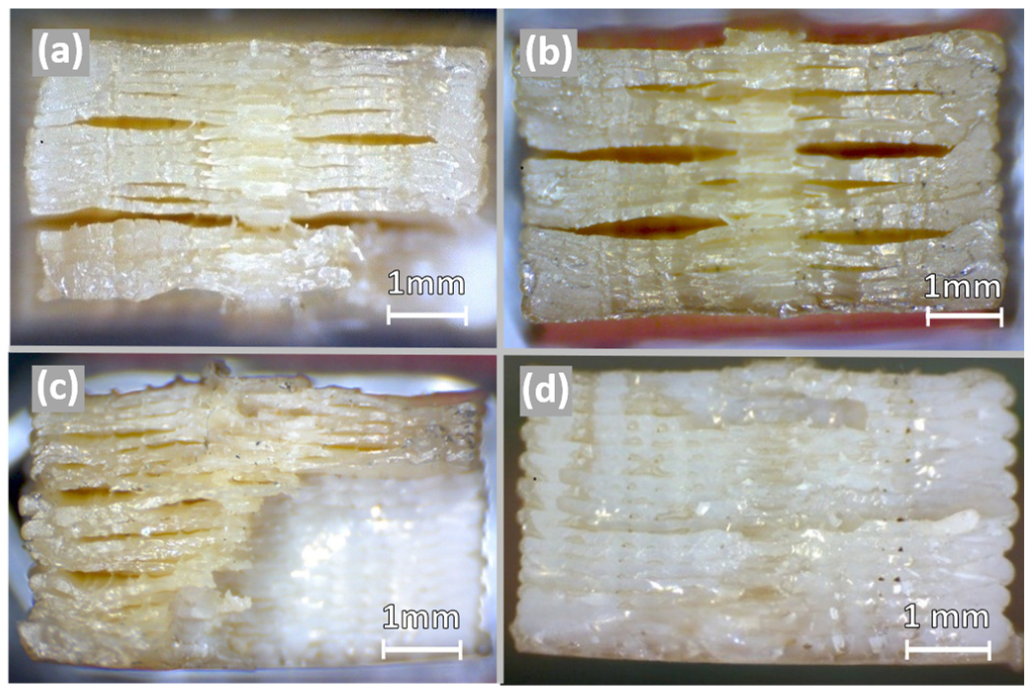
3.2. Fracture Surface Analysis
4. Conclusions
Author Contributions
Funding
Institutional Review Board Statement
Data Availability Statement
Conflicts of Interest
References
- Sachs, E.; Cima, M.; Cornie, J.; Brancazio, D.; Bredt, J.; Curodeau, A.; Fan, T.; Khanuja, S.; Lauder, A.; Lee, J.; et al. Three-Dimensional Printing: The Physics and Implications of Additive Manufacturing. CIRP Ann.—Manuf. Technol. 1993, 42, 257–260. [Google Scholar] [CrossRef]
- Gibson, I.; Rosen, D.; Stucker, B.; Khorasani, M. Additive Manufacturing Technologies, 3rd ed.; Springer International Publishing: New York, NY, USA, 2021; ISBN 978-3-030-56127-7. [Google Scholar]
- Thompson, M.K.; Moroni, G.; Vaneker, T.; Fadel, G.; Campbell, R.I.; Gibson, I.; Bernard, A.; Schulz, J.; Graf, P.; Ahuja, B.; et al. Design for Additive Manufacturing: Trends, Opportunities, Considerations, and Constraints. CIRP Ann.—Manuf. Technol. 2016, 65, 737–760. [Google Scholar] [CrossRef]
- Haryńska, A.; Carayon, I.; Kosmela, P.; Szeliski, K.; Łapiński, M.; Pokrywczyńska, M.; Kucińska-Lipka, J.; Janik, H. A Comprehensive Evaluation of Flexible FDM/FFF 3D Printing Filament as a Potential Material in Medical Application. Eur. Polym. J. 2020, 138, 109958. [Google Scholar] [CrossRef]
- Garcia, J.; Yang, Z.L.; Mongrain, R.; Leask, R.L.; Lachapelle, K. 3D Printing Materials and Their Use in Medical Education: A Review of Current Technology and Trends for the Future. BMJ Simul. Technol. Enhanc. Learn. 2018, 4, 27–40. [Google Scholar] [CrossRef] [PubMed]
- Ali, M.A.; Rajabi, M.; Sudhir Sali, S. Additive Manufacturing Potential for Medical Devices and Technology. Curr. Opin. Chem. Eng. 2020, 28, 127–133. [Google Scholar] [CrossRef]
- Kurtz, S.M.; Devine, J.N. PEEK Biomaterials in Trauma, Orthopedic, and Spinal Implants. Biomaterials 2007, 28, 4845–4869. [Google Scholar] [CrossRef] [PubMed]
- Kurtz, S.M. PEEK Biomaterials Handbook, 1st ed.; Elsevier: Amsterdam, The Netherlands, 2012; ISBN 978-1-4377-4463-7. [Google Scholar]
- Green, S.; Schlegel, J. A Polyaryletherketone Biomaterial for Use in Medical Implant Applications. Polym. Med. Ind. Proc. 2001, 1–7. [Google Scholar]
- Weinans, H.; Huiskes, R.; Grootenboer, H.J. Effects of Material Properties of Femoral Hip Components on Bone Remodeling. J. Orthop. Res. 1992, 10, 845–853. [Google Scholar] [CrossRef]
- Basgul, C.; Yu, T.; Macdonald, D.W.; Siskey, R.; Marcolongo, M.; Kurtz, S.M. Structure-Property Relationships for 3D-Printed PEEK Intervertebral Lumbar Cages Produced Using Fused Filament Fabrication. J. Mater. Res. 2018, 33, 2040–2051. [Google Scholar] [CrossRef]
- Basgul, C.; Yu, T.; MacDonald, D.W.; Siskey, R.; Marcolongo, M.; Kurtz, S.M. Does Annealing Improve the Interlayer Adhesion and Structural Integrity of FFF 3D Printed PEEK Lumbar Spinal Cages? J. Mech. Behav. Biomed. Mater. 2020, 102, 103455. [Google Scholar] [CrossRef]
- Petersmann, S.; Smith, J.A.; Schäfer, U.; Arbeiter, F. Material Extrusion-Based Additive Manufacturing of Polyetheretherketone Cranial Implants: Mechanical Performance and Print Quality. J. Mater. Res. Technol. 2023, 22, 642–657. [Google Scholar] [CrossRef]
- Rendas, P.; Figueiredo, L.; Machado, C.; Mourão, A.; Vidal, C.; Soares, B. Mechanical Performance and Bioactivation of 3D-Printed PEEK for High-Performance Implant Manufacture: A Review. Prog. Biomater. 2022, 12, 89–111. [Google Scholar] [CrossRef]
- Naffakh, M.; Gómez, M.A.; Ellis, G.; Marco, C. Thermal Properties, Structure and Morphology of PEEK/Thermotropic Liquid Crystalline Polymer Blends. Polym. Int. 2003, 52, 1876–1886. [Google Scholar] [CrossRef]
- Talbott, M.F.; Springer, G.S.; Berglund, L.A. The Effects of Crystallinity on the Mechanical Properties of PEEK Polymer and Graphite Fiber Reinforced PEEK. J. Compos. Mater. 1987, 21, 1056–1081. [Google Scholar] [CrossRef]
- Yang, C.; Tian, X.; Li, D.; Cao, Y.; Zhao, F.; Shi, C. Influence of Thermal Processing Conditions in 3D Printing on the Crystallinity and Mechanical Properties of PEEK Material. J. Mater. Process. Technol. 2017, 248, 1–7. [Google Scholar] [CrossRef]
- Zhao, Y.; Zhao, K.; Li, Y.; Chen, F. Mechanical Characterization of Biocompatible PEEK by FDM. J. Manuf. Process. 2020, 56, 28–42. [Google Scholar] [CrossRef]
- Basgul, C.; Thieringer, F.M.; Kurtz, S.M. Heat Transfer-Based Non-Isothermal Healing Model for the Interfacial Bonding Strength of Fused Filament Fabricated Polyetheretherketone. Addit. Manuf. 2021, 46, 102097. [Google Scholar] [CrossRef]
- Bellehumeur, C.; Li, L.; Sun, Q.; Gu, P. Modeling of Bond Formation between Polymer Filaments in the Fused Deposition Modeling Process. J. Manuf. Process. 2004, 6, 170–178. [Google Scholar] [CrossRef]
- Bakrani Balani, S.; Mokhtarian, H.; Coatanéa, E.; Chabert, F.; Nassiet, V.; Cantarel, A. Integrated Modeling of Heat Transfer, Shear Rate, and Viscosity for Simulation-Based Characterization of Polymer Coalescence during Material Extrusion. J. Manuf. Process. 2023, 90, 443–459. [Google Scholar] [CrossRef]
- Vaezi, M.; Yang, S. Extrusion-Based Additive Manufacturing of PEEK for Biomedical Applications. Virtual Phys. Prototyp. 2015, 10, 123–135. [Google Scholar] [CrossRef]
- Wang, P.; Zou, B.; Xiao, H.; Ding, S.; Huang, C. Effects of Printing Parameters of Fused Deposition Modeling on Mechanical Properties, Surface Quality, and Microstructure of PEEK. J. Mater. Process. Technol. 2019, 271, 62–74. [Google Scholar] [CrossRef]
- Es-Said, O.S.; Foyos, J.; Noorani, R.; Mendelson, M.; Marloth, R.; Pregger, B.A. Effect of Layer Orientation on Mechanical Properties of Rapid Prototyped Samples. Mater. Manuf. Process. 2000, 15, 107–122. [Google Scholar] [CrossRef]
- Ahn, S.H.; Montero, M.; Odell, D.; Roundy, S.; Wright, P.K. Anisotropic Material Properties of Fused Deposition Modeling ABS. Rapid Prototyp. J. 2002, 8, 248–257. [Google Scholar] [CrossRef]
- Masood, S.H.; Mau, K.; Song, W.Q. Tensile Properties of Processed FDM Polycarbonate Material. Mater. Sci. Forum 2010, 654–656, 2556–2559. [Google Scholar] [CrossRef]
- Durgun, I.; Ertan, R. Experimental Investigation of FDM Process for Improvement of Mechanical Properties and Production Cost. Rapid Prototyp. J. 2014, 20, 228–235. [Google Scholar] [CrossRef]
- Wu, W.; Geng, P.; Li, G.; Zhao, D.; Zhang, H.; Zhao, J. Influence of Layer Thickness and Raster Angle on the Mechanical Properties of 3D-Printed PEEK and a Comparative Mechanical Study between PEEK and ABS. Materials 2015, 8, 5834–5846. [Google Scholar] [CrossRef] [PubMed]
- Pu, J.; McIlroy, C.; Jones, A.; Ashcroft, I. Understanding Mechanical Properties in Fused Filament Fabrication of Polyether Ether Ketone. Addit. Manuf. 2021, 37, 101673. [Google Scholar] [CrossRef]
- Rinaldi, M.; Ghidini, T.; Cecchini, F.; Brandao, A.; Nanni, F. Additive Layer Manufacturing of Poly (Ether Ether Ketone) via FDM. Compos. Part B Eng. 2018, 145, 162–172. [Google Scholar] [CrossRef]
- Silva, M.; Shepherd, E.F.; Jackson, W.O.; Dorey, F.J.; Schmalzried, T.P. Average Patient Walking Activity Approaches 2 Million Cycles per Year: Pedometers under-Record Walking Activity. J. Arthroplast. 2002, 17, 693–697. [Google Scholar] [CrossRef]
- Zadpoor, A.A. Mechanical Performance of Additively Manufactured Meta-Biomaterials. Acta Biomater. 2019, 85, 41–59. [Google Scholar] [CrossRef]
- Trotignon, J.P.; Verdu, J.; Martin, C.; Morel, E. Fatigue Behaviour of Some Temperature-Resistant Polymers. J. Mater. Sci. 1993, 28, 2207–2213. [Google Scholar] [CrossRef]
- Saib, K.S.; Isaac, D.H.; Evans, W.J. Effects of Processing Variables on Fatigue in Molded Peek and Its Short Fiber Composites. Mater. Manuf. Process. 1994, 9, 829–850. [Google Scholar] [CrossRef]
- Berer, M.; Major, Z.; Pinter, G.; Constantinescu, D.M.; Marsavina, L. Investigation of the Dynamic Mechanical Behavior of Polyetheretherketone (PEEK) in the High Stress Tensile Regime. Mech. Time-Depend. Mater. 2014, 18, 663–684. [Google Scholar] [CrossRef]
- Abbasnezhad, N.; Khavandi, A.; Fitoussi, J.; Arabi, H.; Shirinbayan, M.; Tcharkhtchi, A. Influence of Loading Conditions on the Overall Mechanical Behavior of Polyether-Ether-Ketone (PEEK). Int. J. Fatigue 2018, 109, 83–92. [Google Scholar] [CrossRef]
- Shrestha, R.; Simsiriwong, J.; Shamsaei, N.; Moser, R.D. Cyclic Deformation and Fatigue Behavior of Polyether Ether Ketone (PEEK). Int. J. Fatigue 2016, 82, 411–427. [Google Scholar] [CrossRef]
- Evans, N.T.; Torstrick, F.B.; Lee, C.S.D.; Dupont, K.M.; Safranski, D.L.; Chang, W.A.; Macedo, A.E.; Lin, A.S.P.; Boothby, J.M.; Whittingslow, D.C.; et al. High-Strength, Surface-Porous Polyether-Ether-Ketone for Load-Bearing Orthopedic Implants. Acta Biomater. 2015, 13, 159–167. [Google Scholar] [CrossRef] [PubMed]
- Avanzini, A.; Donzella, G.; Gallina, D.; Pandini, S.; Petrogalli, C. Fatigue Behavior and Cyclic Damage of Peek Short Fiber Reinforced Composites. Compos. Part B Eng. 2013, 45, 397–406. [Google Scholar] [CrossRef]
- Avanzini, A.; Battini, D.; Petrogalli, C.; Pandini, S.; Donzella, G. Anisotropic Behaviour of Extruded Short Carbon Fibre Reinforced PEEK Under Static and Fatigue Loading. Appl. Compos. Mater. 2022, 29, 1041–1060. [Google Scholar] [CrossRef]
- Abu Bakar, M.S.; Cheng, M.H.W.; Tang, S.M.; Yu, S.C.; Liao, K.; Tan, C.T.; Khor, K.A.; Cheang, P. Tensile Properties, Tension-Tension Fatigue and Biological Response of Polyetheretherketone-Hydroxyapatite Composites for Load-Bearing Orthopedic Implants. Biomaterials 2003, 24, 2245–2250. [Google Scholar] [CrossRef]
- Tang, S.M.; Cheang, P.; Abu Bakar, M.S.; Khor, K.A.; Liao, K. Tension-Tension Fatigue Behavior of Hydroxyapatite Reinforced Polyetheretherketone Composites. Int. J. Fatigue 2004, 26, 49–57. [Google Scholar] [CrossRef]
- Pan, Y.; Mao, J.; Ding, J. Fatigue Performance of Hydroxyapatite Filled Polyetheretherketone Functional Gradient Biocomposites. Mater. Technol. 2018, 33, 761–768. [Google Scholar] [CrossRef]
- Nishitani, H.; Noguchi, H.; Kim, Y.H.; Yamaguchi, T. Fatigue Strength of Plain and Notched Specimens of Short Carbon-Fiber Reinforced Poly-Ether-Ether-Ketone (In Comparison with Poly-Ether-Ether-Ketone). J. Soc. Mater. Sci. 1992, 41, 740–745. [Google Scholar] [CrossRef]
- Avanzini, A.; Petrogalli, C.; Battini, D.; Donzella, G. Influence of Micro-Notches on the Fatigue Strength and Crack Propagation of Unfilled and Short Carbon Fiber Reinforced PEEK. Mater. Des. 2018, 139, 447–456. [Google Scholar] [CrossRef]
- Rendas, P.; Figueiredo, L.; Geraldo, M.; Vidal, C.; Soares, B.A. Improvement of Tensile and Flexural Properties of 3D Printed PEEK through the Increase of Interfacial Adhesion. J. Manuf. Process. 2023, 93, 260–274. [Google Scholar] [CrossRef]
- Apium PEEK 450 Natural Datasheet. Available online: https://apiumtec.com/en/case-studies-datasheets (accessed on 28 September 2023).
- ASTM Standard D638; Standard Test Method for Tensile Properties of Plastics. ASTM International: West Conshohocken, PA, USA, 2003.
- Hu, B.; Duan, X.; Xing, Z.; Xu, Z.; Du, C.; Zhou, H.; Chen, R.; Shan, B. Improved Design of Fused Deposition Modeling Equipment for 3D Printing of High-Performance PEEK Parts. Mech. Mater. 2019, 137, 103139. [Google Scholar] [CrossRef]
- ASTM Standard D7791; Standard Test Method for Uniaxial Fatigue Properties of Plastics. ASTM International: West Conshohocken, PA, USA, 2012.
- Sobieraj, M.C.; Murphy, J.E.; Brinkman, J.G.; Kurtz, S.M.; Rimnac, C.M. Notched Fatigue Behavior of PEEK. Biomaterials 2010, 31, 9156–9162. [Google Scholar] [CrossRef] [PubMed]
- Andrzejewska, A.; Pejkowski, L.; Topoliński, T. Tensile and Fatigue Behavior of Additive Manufactured Polylactide. 3D Print. Addit. Manuf. 2019, 6, 272–280. [Google Scholar] [CrossRef]
- Ezeh, O.H.; Susmel, L. Fatigue Strength of Additively Manufactured Polylactide (PLA): Effect of Raster Angle and Non-Zero Mean Stresses. Int. J. Fatigue 2019, 126, 319–326. [Google Scholar] [CrossRef]
- Jerez-Mesa, R.; Travieso-Rodriguez, J.A.; Llumà-Fuentes, J.; Gomez-Gras, G.; Puig, D. Fatigue Lifespan Study of PLA Parts Obtained by Additive Manufacturing. Procedia Manuf. 2017, 13, 872–879. [Google Scholar] [CrossRef]
- Dadashi, A.; Azadi, M. Experimental Bending Fatigue Data of Additive-Manufactured PLA Biomaterial Fabricated by Different 3D Printing Parameters. Prog. Addit. Manuf. 2023, 8, 255–263. [Google Scholar] [CrossRef]
- Puigoriol-Forcada, J.M.; Alsina, A.; Salazar-Martín, A.G.; Gomez-Gras, G.; Pérez, M.A. Flexural Fatigue Properties of Polycarbonate Fused-Deposition Modelling Specimens. Mater. Des. 2018, 155, 414–421. [Google Scholar] [CrossRef]
- Fischer, M.; Schöppner, V. Fatigue Behavior of FDM Parts Manufactured with Ultem 9085. Jom 2017, 69, 563–568. [Google Scholar] [CrossRef]
- Azadi, M.; Dadashi, A.; Dezianian, S.; Kianifar, M.; Torkaman, S.; Chiyani, M. High-Cycle Bending Fatigue Properties of Additive-Manufactured ABS and PLA Polymers Fabricated by Fused Deposition Modeling 3D-Printing. Forces Mech. 2021, 3, 100016. [Google Scholar] [CrossRef]
- Ziemian, S.; Okwara, M.; Ziemian, C.W. Tensile and Fatigue Behavior of Layered Acrylonitrile Butadiene Styrene. Rapid Prototyp. J. 2015, 21, 270–278. [Google Scholar] [CrossRef]
- Hassanifard, S.; Behdinan, K. Anisotropy and Internal Flaws Effects on Fatigue Response of Notched 3D-Printed PLA Parts. Mater. Today Commun. 2023, 35, 105734. [Google Scholar] [CrossRef]
- Kiani, P.; Sedighi, M.; Kasaeian-Naeini, M.; Jabbari, A.H. High Cycle Fatigue Behavior and Thermal Properties of PLA/PCL Blends Produced by Fused Deposition Modeling. J. Polym. Res. 2023, 30, 264. [Google Scholar] [CrossRef]
- Goodman, J. Mechanics Applied to Engineering, 8th ed.; Longmans Green & Co., Ed.; Longmans, Green: Harlow, UK, 1862. [Google Scholar]
- Brillhart, M.; Gregory, B.L.; Botsis, J. Fatigue Fracture Behaviour of PEEK: 1. Effects of Load Level. Polymer 1991, 32, 1605–1611. [Google Scholar] [CrossRef]
- Rae, P.J.; Brown, E.N.; Orler, E.B. The Mechanical Properties of Poly(Ether-Ether-Ketone) (PEEK) with Emphasis on the Large Compressive Strain Response. Polymer 2007, 48, 598–615. [Google Scholar] [CrossRef]


| Filament Material Properties | |
|---|---|
| Density, ρ [g/cm3] | 1.3 |
| Elastic modulus, E [GPa] | 4.0 |
| [MPa] | 98 |
| [%] | 45 |
| [°C] | 143 |
| [°C] | 343 |
| FFF Printing Parameters | ||||
|---|---|---|---|---|
| Nozzle temperature | 485 °C | Layer height | 0.20 mm | |
| Bed temperature | 130 °C | Extrusion width | 0.48 mm | |
| Zone heater temperature | 130 °C | Printing speed | 2000 mm/min | |
| Deposition pattern | Concentric | Underspeed | Outline | 40% |
| Deposition sequence | Inside-Out | Solid infill | 80% | |
| Perimeter shells | 2 | First layer | 40% | |
| Brim outlines | 25 | X/Y movement speed | 4800 mm/min | |
| Stress Level | [MPa] | [MPa] | [MPa] | Specimen Number (#) | [mm2] | [N] | [N] |
|---|---|---|---|---|---|---|---|
| 75% | 65.0 | 39.0 | 26.0 | 7 | 26.43 | 1030 | 687 |
| 8 | 26.52 | 1030 | 690 | ||||
| 85% | 73.7 | 44.2 | 29.5 | 1 | 26.45 | 1170 | 780 |
| 2 | 26.29 | 1160 | 775 | ||||
| 3 | 26.67 | 1180 | 786 | ||||
| 92% | 79.8 | 47.9 | 31.9 | 4 | 27.82 | 1330 | 888 |
| 95% | 82.4 | 49.5 | 32.9 | 5 | 25.97 | 1280 | 856 |
| 6 | 24.96 | 1230 | 822 |
| Specimen Number | [MPa] | [MPa] | |
|---|---|---|---|
| 1 | 44.2 | 29.5 | 327,112 |
| 2 | 44.2 | 29.5 | 662,683 |
| 3 | 44.2 | 29.5 | 369,762 |
| 4 | 47.9 | 31.9 | 36,506 |
| 5 | 49.5 | 32.9 | 315,418 |
| 6 | 49.5 | 32.9 | 70,159 |
| 7 | 39.0 | 26.0 | 634,019 |
| 8 | 39.0 | 26.0 | 10,000,000 |
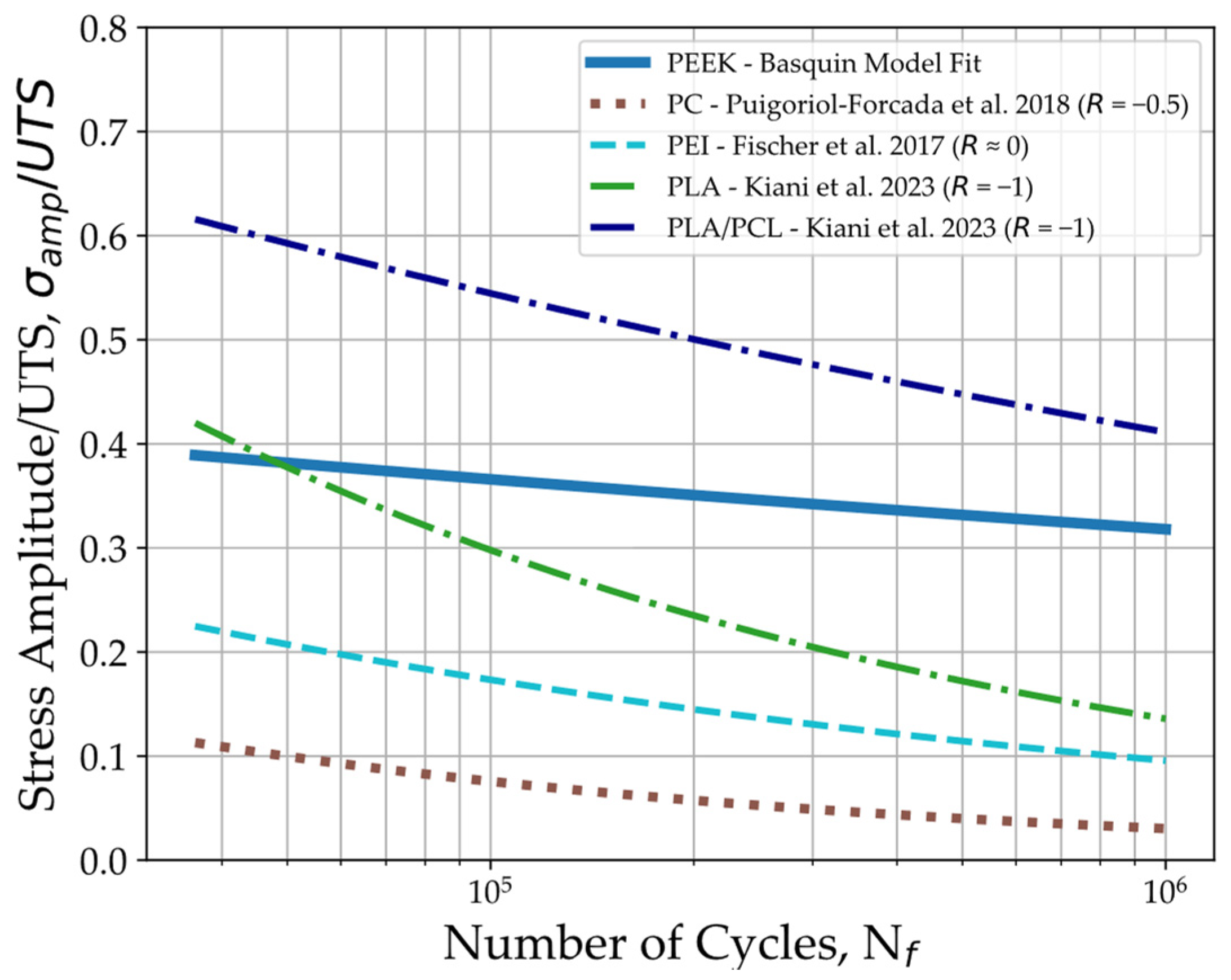
| Ref. | Specimen Type | [MPa] | [MPa] | [MPa] | [MPa] |
|---|---|---|---|---|---|
| In the present study | 3D-printed PEEK | 86.7 | 39.0 | 26.0 | 47.3 |
| Avanzini et al. [40] | Extruded PEEK | 102.0 | 40.0 | 40.0 | 65.8 |
| Sobieraj et al. [51] | Extruded PEEK—moderate notch | 112.0 * | 42.0 ** | 42.0 ** | 67.1 |
| Extruded PEEK—razor notch | 85.0 * | 27.4 ** | 27.4 ** | 40.5 | |
| Puigoriol-Forcada et al. [56] | 3D-printed PC | 48.7 | 4.4 ** | 1.5 ** | 1.6 |
| Fischer et al. [57] | 3D-printed PEI | 72.5 * | 6.9 ** | 6.9 ** | 7.7 |
| Kiani et al. [61] | 3D-printed PLA | 61.3 | 0.0 | 15.5 | 15.5 |
| 3D-printed PLA/PCL (80/20) | 33.5 | 0.0 | 13.6 | 13.6 |
Disclaimer/Publisher’s Note: The statements, opinions and data contained in all publications are solely those of the individual author(s) and contributor(s) and not of MDPI and/or the editor(s). MDPI and/or the editor(s) disclaim responsibility for any injury to people or property resulting from any ideas, methods, instructions or products referred to in the content. |
© 2023 by the authors. Licensee MDPI, Basel, Switzerland. This article is an open access article distributed under the terms and conditions of the Creative Commons Attribution (CC BY) license (https://creativecommons.org/licenses/by/4.0/).
Share and Cite
Rendas, P.; Imperadeiro, A.; Martins, R.F.; Soares, B.A.R. High-Cycle Fatigue Behaviour of Polyetheretherketone (PEEK) Produced by Additive Manufacturing. Polymers 2024, 16, 18. https://doi.org/10.3390/polym16010018
Rendas P, Imperadeiro A, Martins RF, Soares BAR. High-Cycle Fatigue Behaviour of Polyetheretherketone (PEEK) Produced by Additive Manufacturing. Polymers. 2024; 16(1):18. https://doi.org/10.3390/polym16010018
Chicago/Turabian StyleRendas, Pedro, Alexandre Imperadeiro, Rui F. Martins, and Bruno A. R. Soares. 2024. "High-Cycle Fatigue Behaviour of Polyetheretherketone (PEEK) Produced by Additive Manufacturing" Polymers 16, no. 1: 18. https://doi.org/10.3390/polym16010018