Article

Experimental Study on Shear-Peeling Debonding Behavior of BFRP Sheet-to-Steel Interfaces

1
Department of Civil Engineering, College of Civil Science and Engineering, Yangzhou University, Yangzhou 225127, China
2
Jiangsu Province Engineering Research Center of Prefabricated Building and Intelligent Construction, Suqian 223800, China
*
Authors to whom correspondence should be addressed.
Polymers 2023, 15(9), 2216; https://doi.org/10.3390/polym15092216
Submission received: 24 March 2023 / Revised: 29 April 2023 / Accepted: 5 May 2023 / Published: 8 May 2023

Abstract

:
In order to study the failure mode and debonding behavior of the interface between BFRP (basalt fiber reinforced polymer) sheet and structural steel under mixed-mode loading conditions, eighteen specimens with different initial angles were tested in this study. The specimens were designed with different initial angles to ensure that the interface performed under mixed-mode loading conditions. The relations between the bond strengths, failure modes, and initial angles were investigated. A new evaluation method to predict the interfacial bond strength under shear-peeling loading mode was proposed. The test results show that specimens with a smaller initial angle are more likely to exhibit a shear debonding failure at the interface between the steel plate and adhesive. In contrast, specimens with a larger initial angle are more likely to exhibit peeling of the interface. The ultimate tensile strength of the specimen is higher with a smaller initial angle. The results predicted by the proposed method are in good agreement with the experimental results.

1. Introduction

Steel structures have many advantages, including excellent seismic performance, high strength, fast construction speed, stable quality, light weight, and green environmental protection [1,2,3,4]. However, due to the external environment as well as internal defects and human factors, steel structures are likely to accumulate damage over the course of their service life. Although traditional welding, bolted connections, and external steel plate reinforcement methods can improve the bearing capacity of the damaged structures, they may also cause further damage and additional weight to the structures [5,6,7,8,9]. There are many advantages to using fiber-reinforced polymer sheets for reinforcement, such as corrosion resistance, light weight, simple construction, environmental friendliness, etc., which can be adopted to improve the bearing strength, corrosion resistance, and compressive buckling capacity of the steel structures [10,11,12,13,14].
The advantages of fiber-reinforced polymer (FRP) include corrosion resistance, light weight, simplicity of construction, no pollution, and superior fatigue resistance. Steel structures can be strengthened using FRP to increase their ultimate strength and buckling resistance, as well as protect them from corrosion [15,16,17,18]. At present, the main fiber-reinforced polymers are carbon-fiber-reinforced polymer (CFRP), glass-fiber-reinforced polymer (GFRP), and basalt-fiber-reinforced polymer (BFRP). Basalt fiber is a pure, natural, inorganic material made from natural rocks. After use, it can be returned to nature without special treatment. In comparison with CFRP and GFRP, BFRP has the advantages of environmental protection, low cost, superior insulation, low hygroscopicity, and abundant raw materials [19,20].
Many researchers have carried out experiments on the bonding properties of FRP-to-steel interface, and corresponding theoretical formulae have been proposed [21,22,23,24,25]. Doroudi et al. [26] investigated the behavior of CFRP-to-steel bonded joints under quasi-static cyclic loading using nine single shear pull-off test specimens, in which three different bond thicknesses and both quasi-static monotonic and quasi-static cyclic loading methods were considered. The results showed that the stiffness of the load-displacement curves tends to decrease with an increasing number of loading cycles. Bocciarelli et al. [27] conducted an experimental study on the fatigue behavior of steel structures retrofitted by FRP materials. The results showed that the fatigue resistance of the interface between the steel plate and the CFRP plate is remarkably superior to that of welded cover plates. Dehghani et al. [28] proposed a new method for the analysis of bonded connections of CFRP and steel substrates. A comparison of results obtained from their proposed model and experimental data showed that the ultimate debonding load could be accurately estimated by their proposed model. In this model, unlike some previous bond-slip models, the ultimate debonding load is independent of the thickness of the adhesive. Biscaia et al. [29] investigated the performance of CFRP-to-steel bonded joints under different temperatures (20 °C, 35 °C, 50 °C, 65 °C, 80 °C, and 95 °C). According to the local bond-slip behavior of the tested specimens, a temperature-dependent bond-slip model with a bi-linear shape was proposed and implemented into commercial software based on the finite element method. Yu et al. [30] conducted an experimental study on the behavior of CFRP-to-steel bonded interfaces by testing a series of single-lap bonded joints. The test results showed that the bond strength of such bonded joints depends strongly on the interfacial fracture energy among other factors. Wu et al. [31] conducted a series of static and fatigue tests on UHM (ultra-high modulus) CFRP plate and steel plate double strap joints to investigate the effect of residual bond strength and residual bond stiffness on bond behavior. Wu et al. [32] studied the bond characteristics between ultra-high modulus (UHM) CFRP laminates with a modulus of 460 GPa and steel through a series of experiments with double strap steel joints bonded with UHM CFRP laminates. The effect of two types of adhesives (Araldite and Sikadur) on the failure modes, bond strength, effective bond length, CFRP strain distribution, adhesive layer shear stress distribution, and bond-slip relationship were discussed. Then, theoretical models were employed for the prediction of the specimen bond strength and effective bond length, and their applicability for UHM CFRP steel joints was verified by comparisons with experimental results. Golewski [33] studied the tensile behavior of double- and triple-adhesive single-lap joints. It was found that the energy required to damage the joint when using double-sided adhesive tape is several times greater than that required to damage a joint made with epoxy. Jawdhari et al. [34] investigated the bond-slip relationship between CFRP rod panels and concrete. They found that the debonding load of a CFRP rod panel is higher than that of an externally bonded conventional CFRP plate of similar cross-sectional area and mechanical properties. Mukhtar et al. [35] tested the adhesive bond between FRP laminate and concrete in both double shear and mixed mode (shear/peeling) using a novel test apparatus. Test results showed that the bond capacity decreases as the peel angle increases. Altaee et al. [36] studied the bond-slip relations of CFRP-steel joints using a new bilinear model. The proposed model resulted in excellent predictions in terms of the ultimate strength, failure mode, and all other interfacial properties. Jawdhari et al. [37] carried out a three-dimensional nonlinear finite element analysis to study the strip panels’ interfacial and flexural properties. As a result, strip panels with finger joints were found to carry more load for a given CFRP thickness and splice plate length.
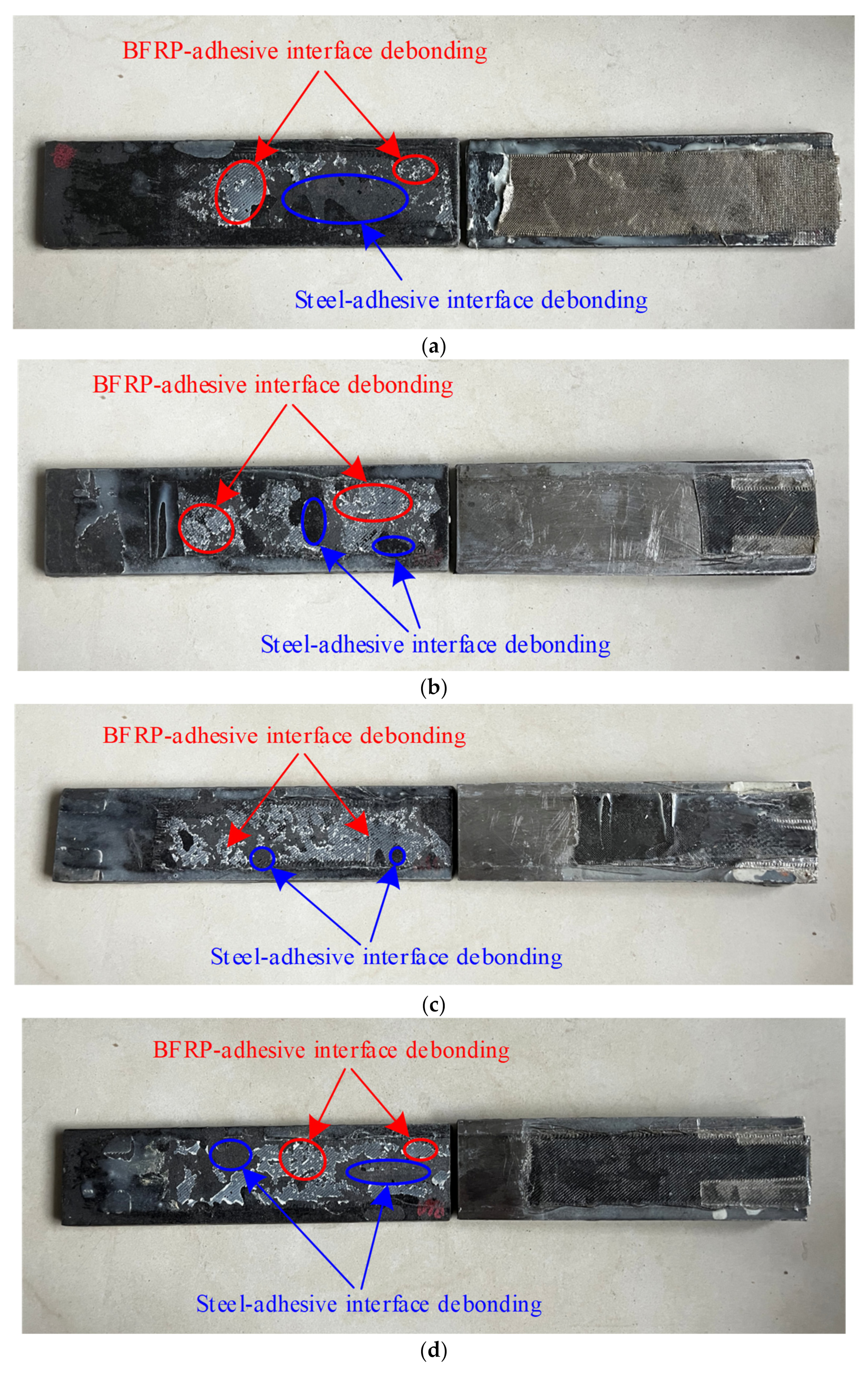
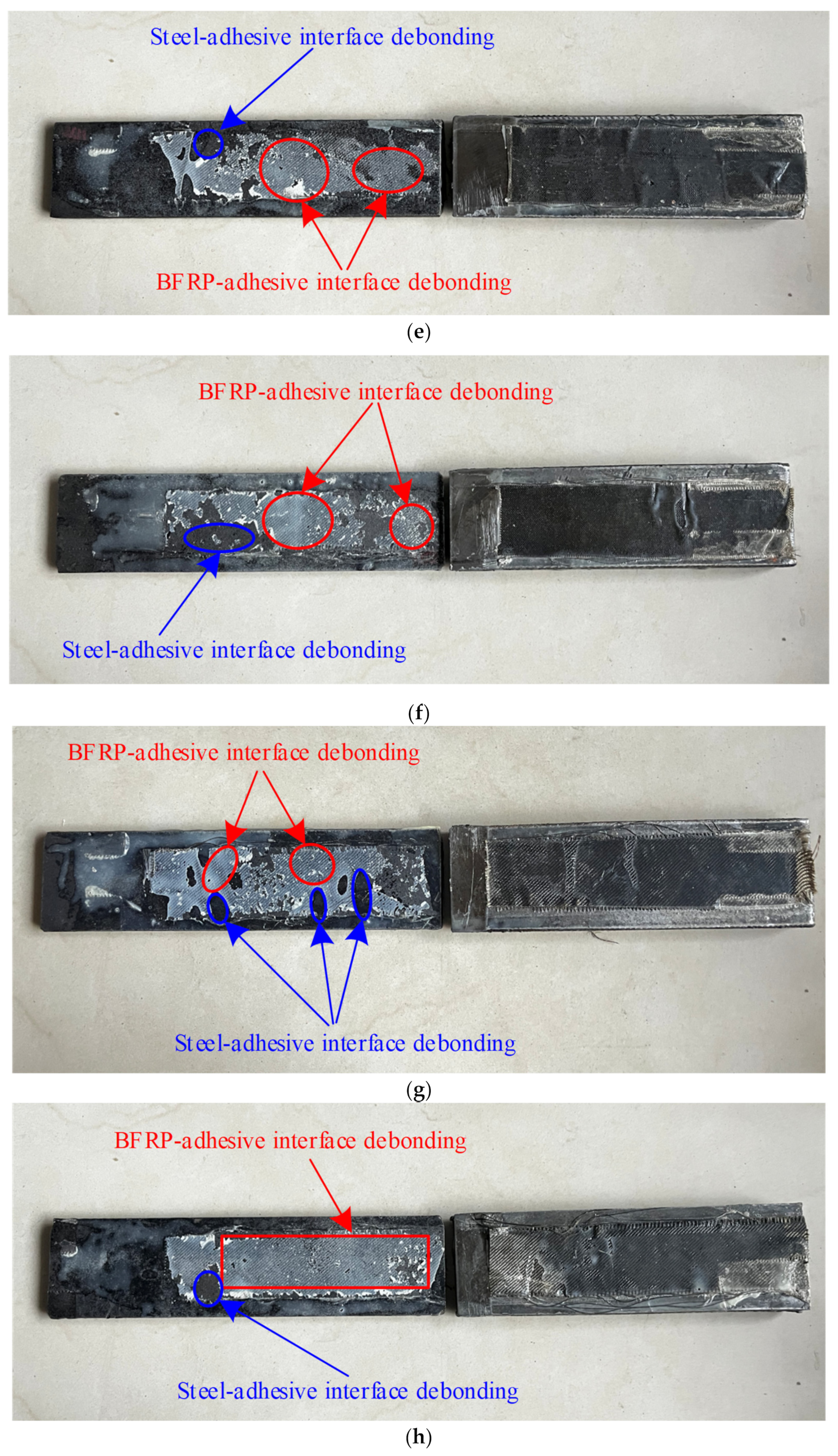
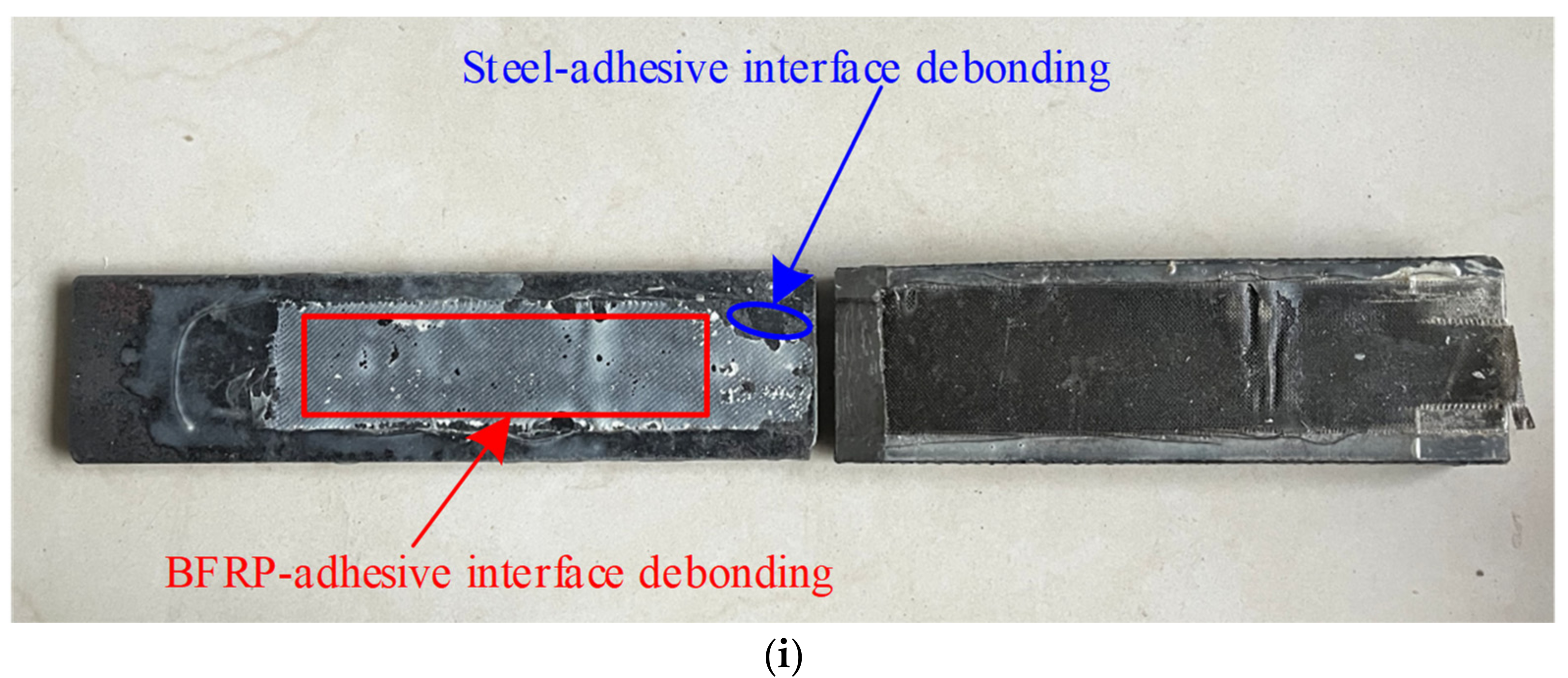
Most of the above studies focused on the bonding behavior of the interfaces regarding shear forces. However, the failure of the FRP-to-steel interface is related to the mixed-mode debonding failure, i.e., the combined actions of shear and peeling forces [38,39,
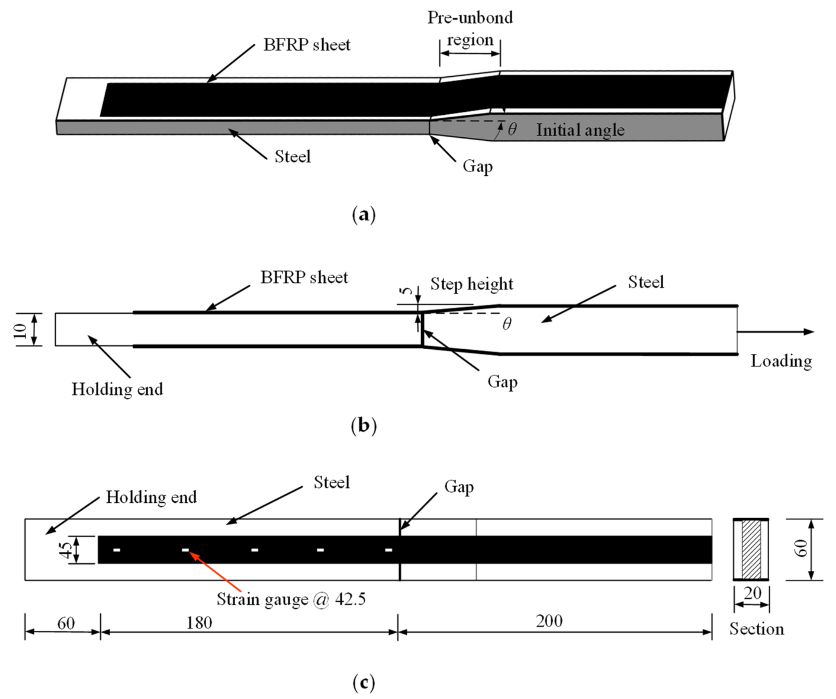
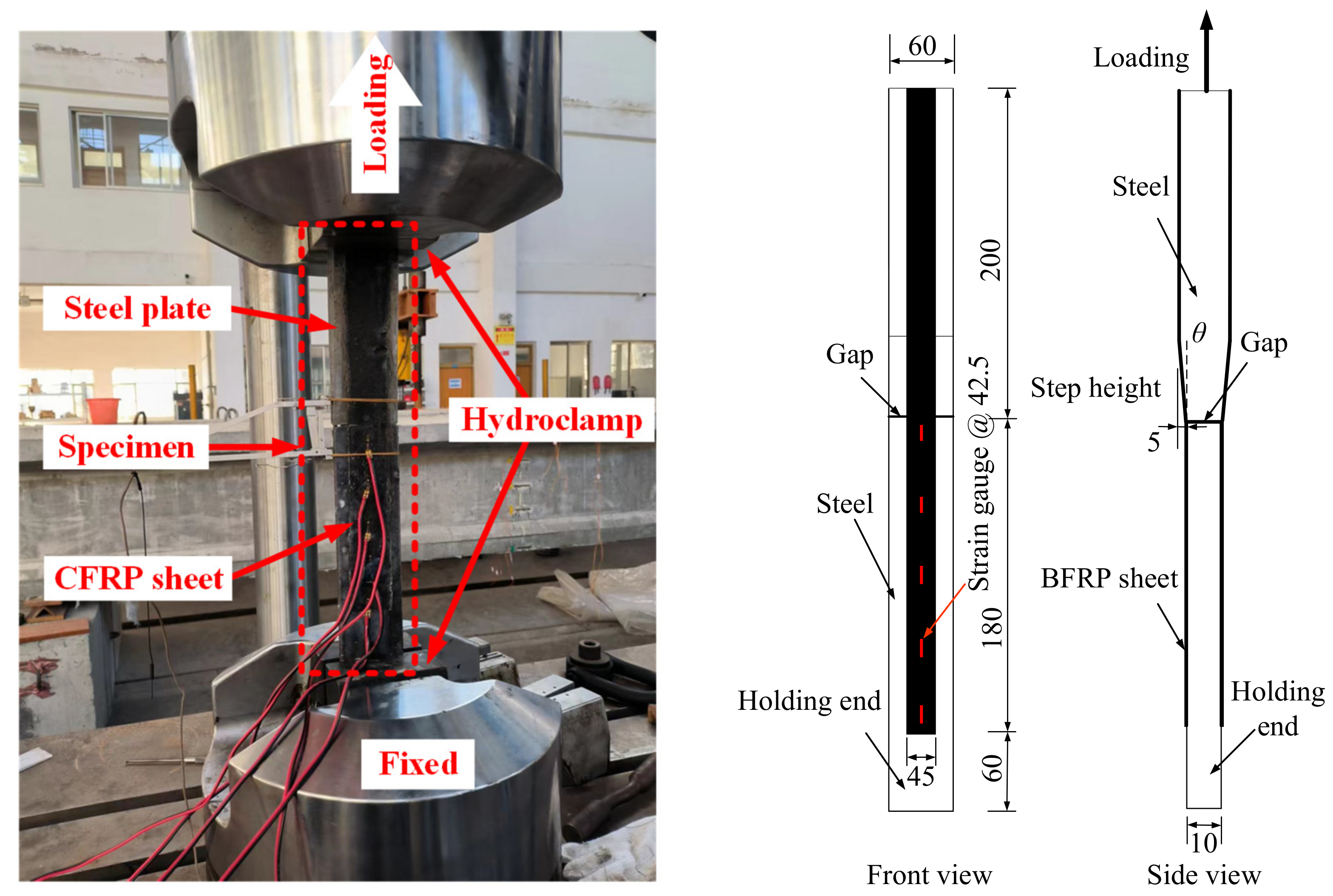
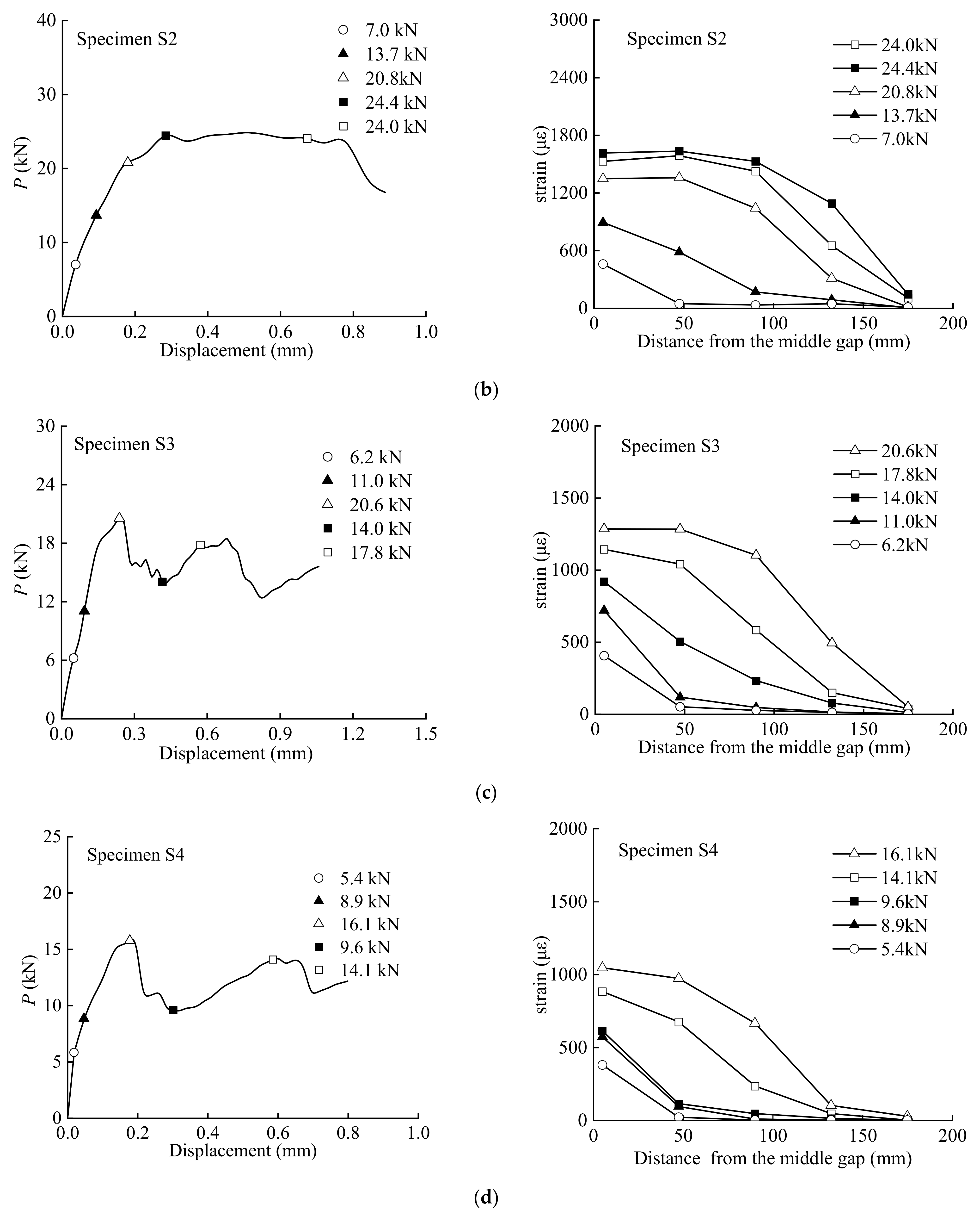
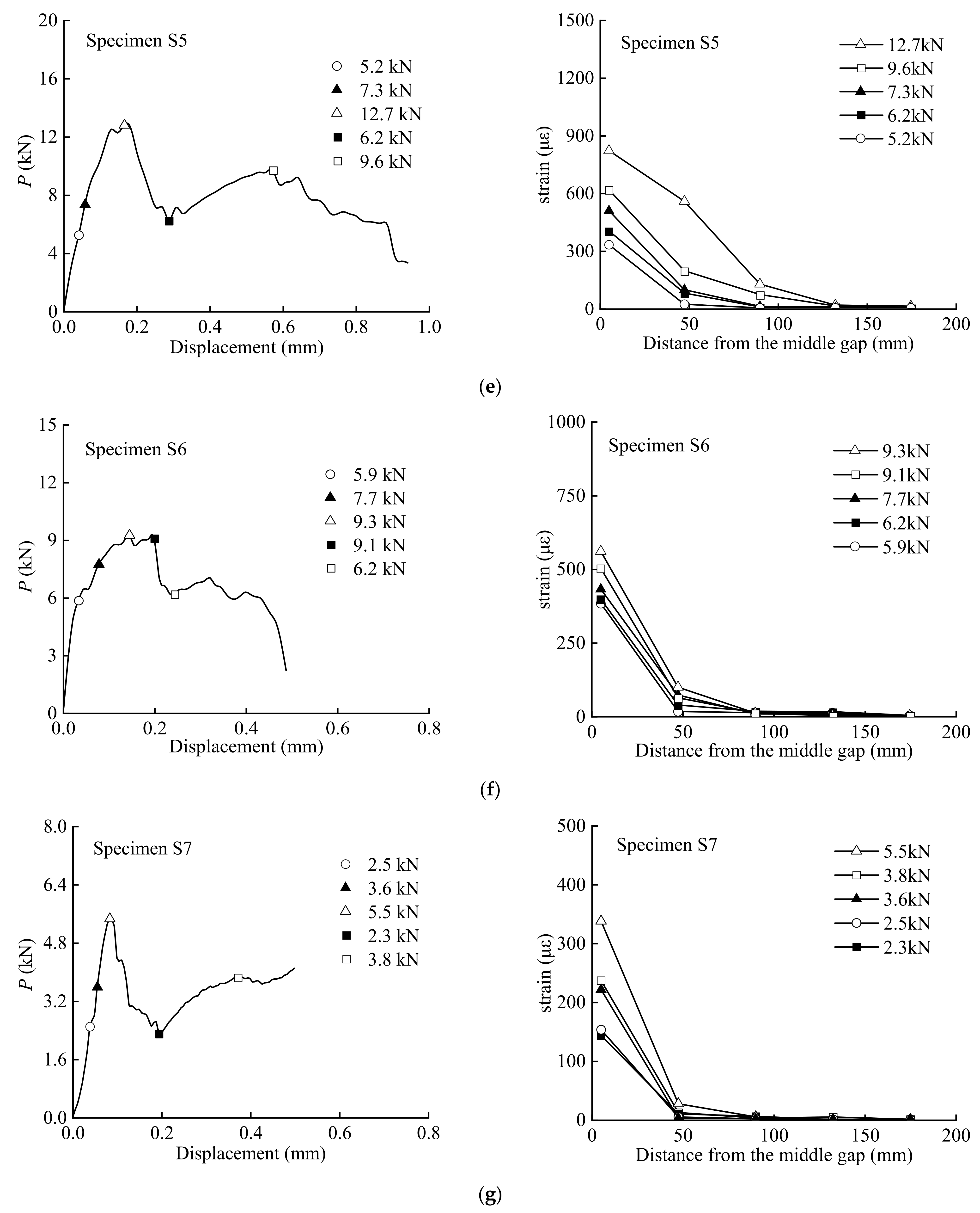
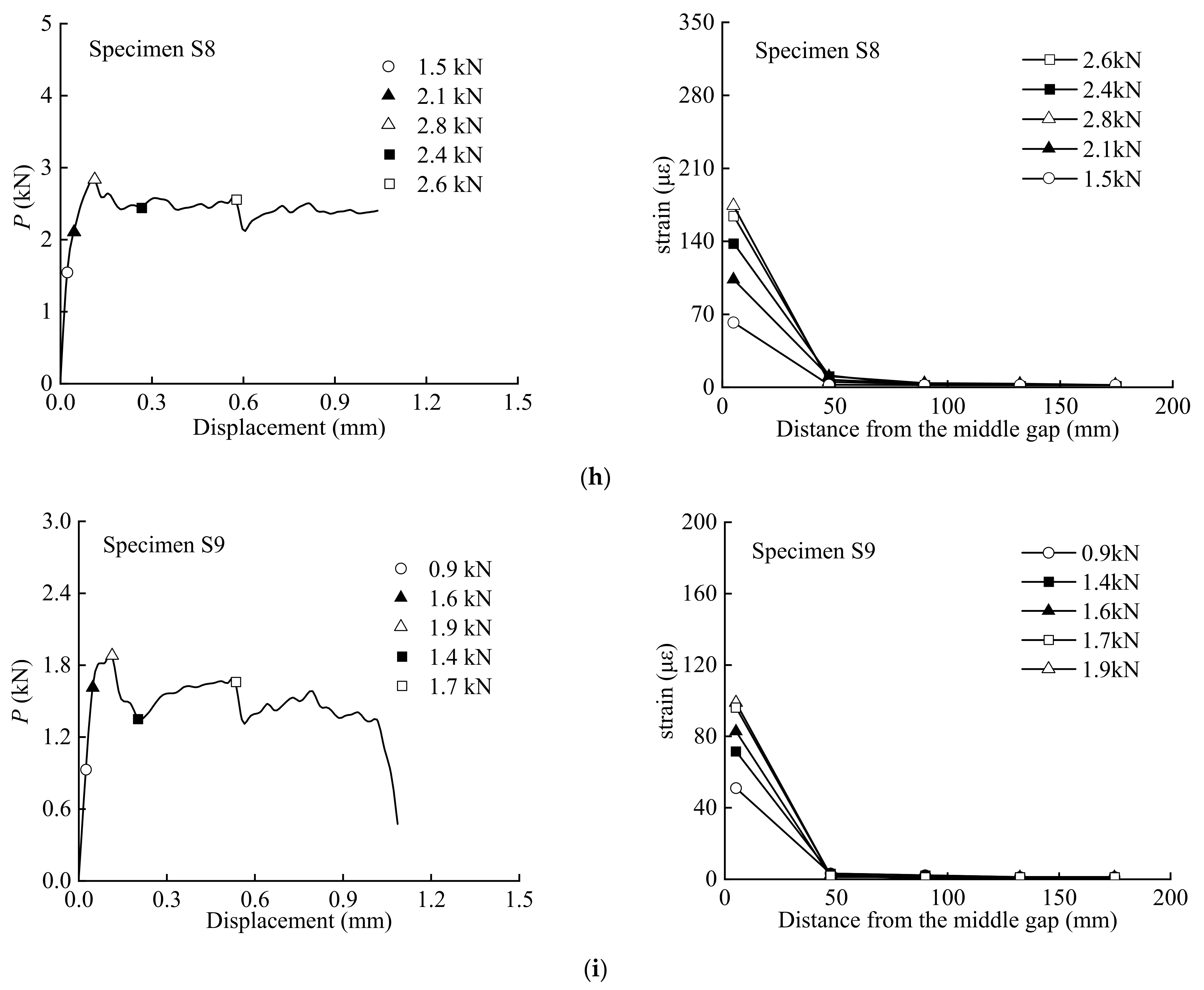
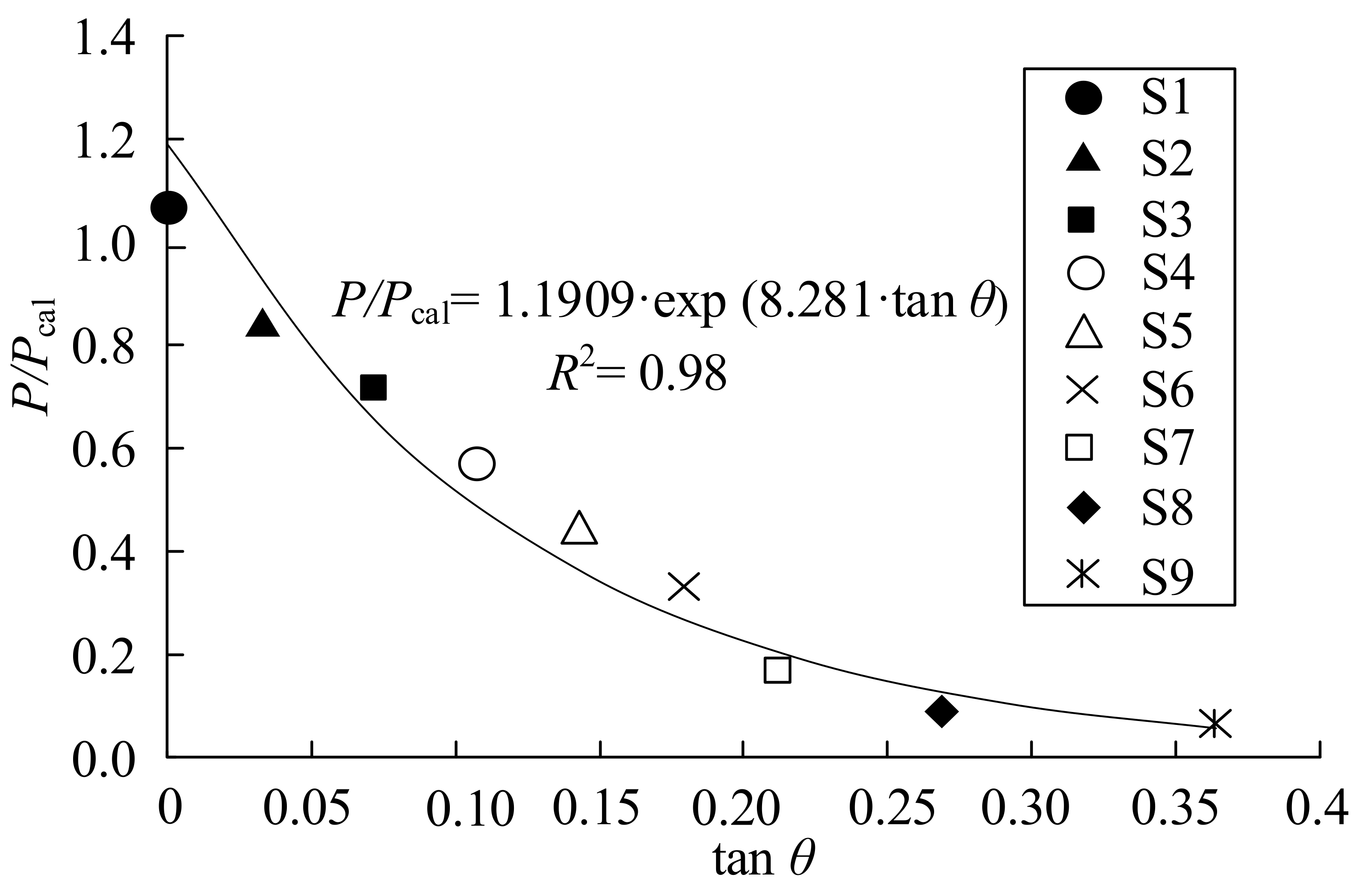
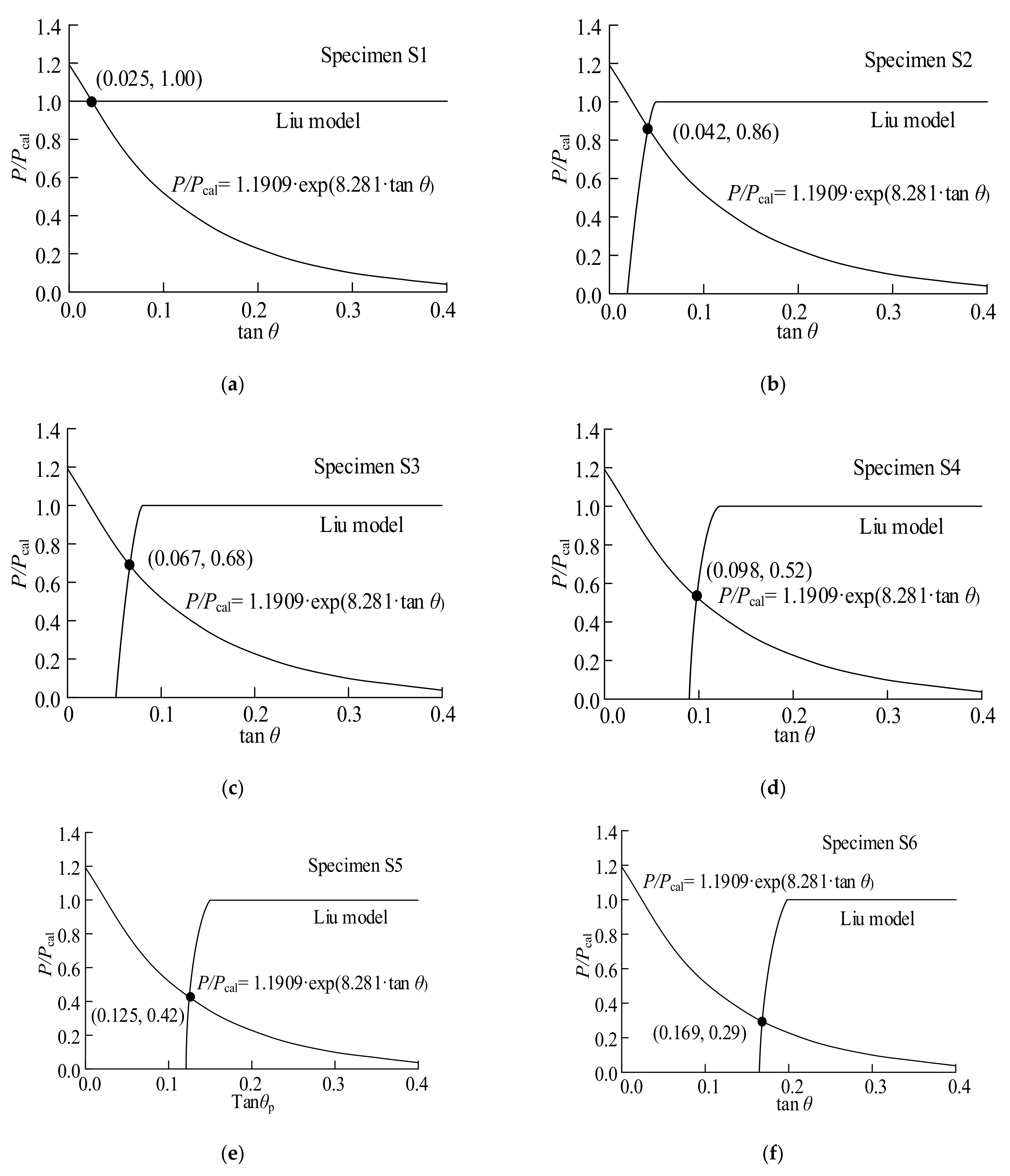
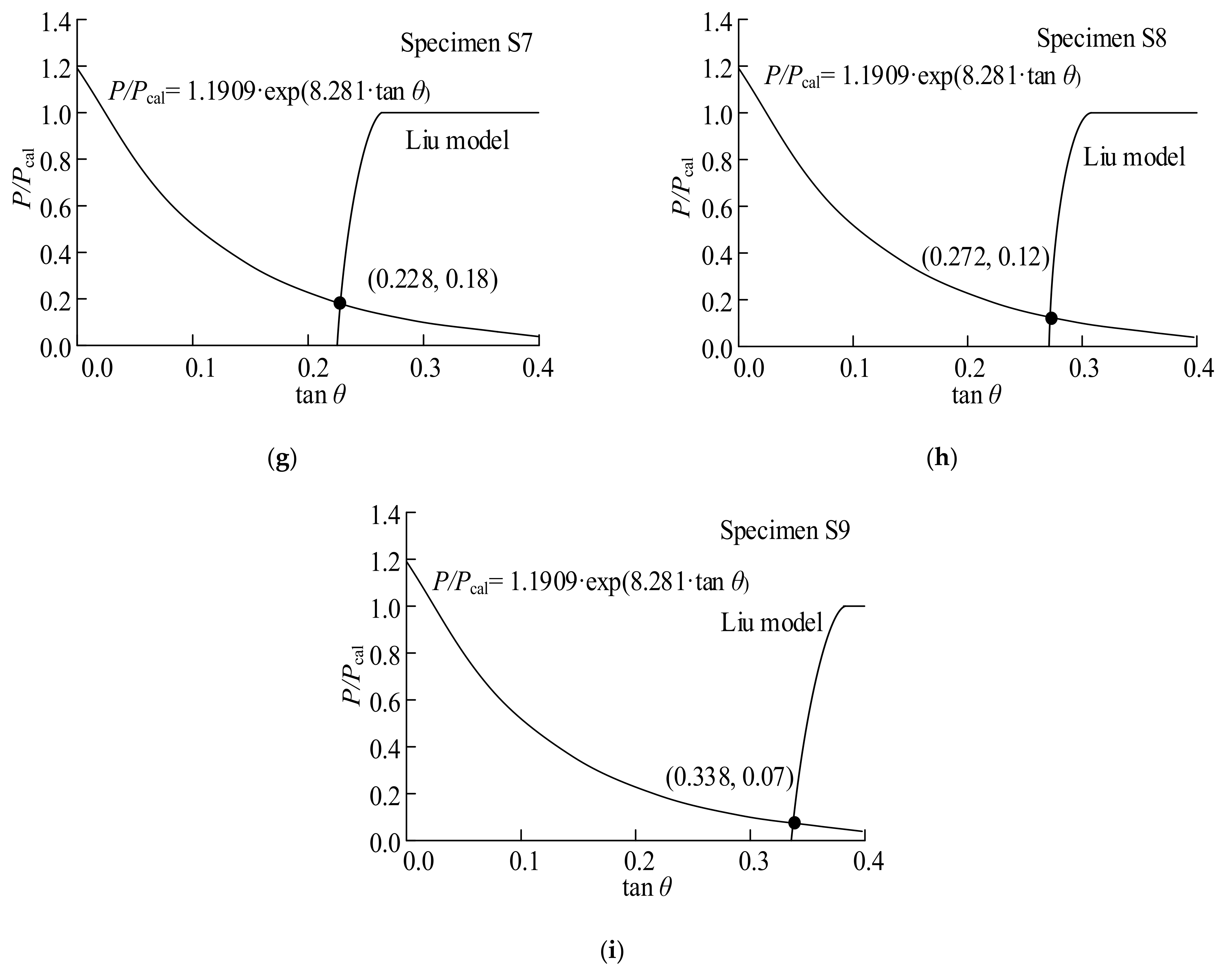
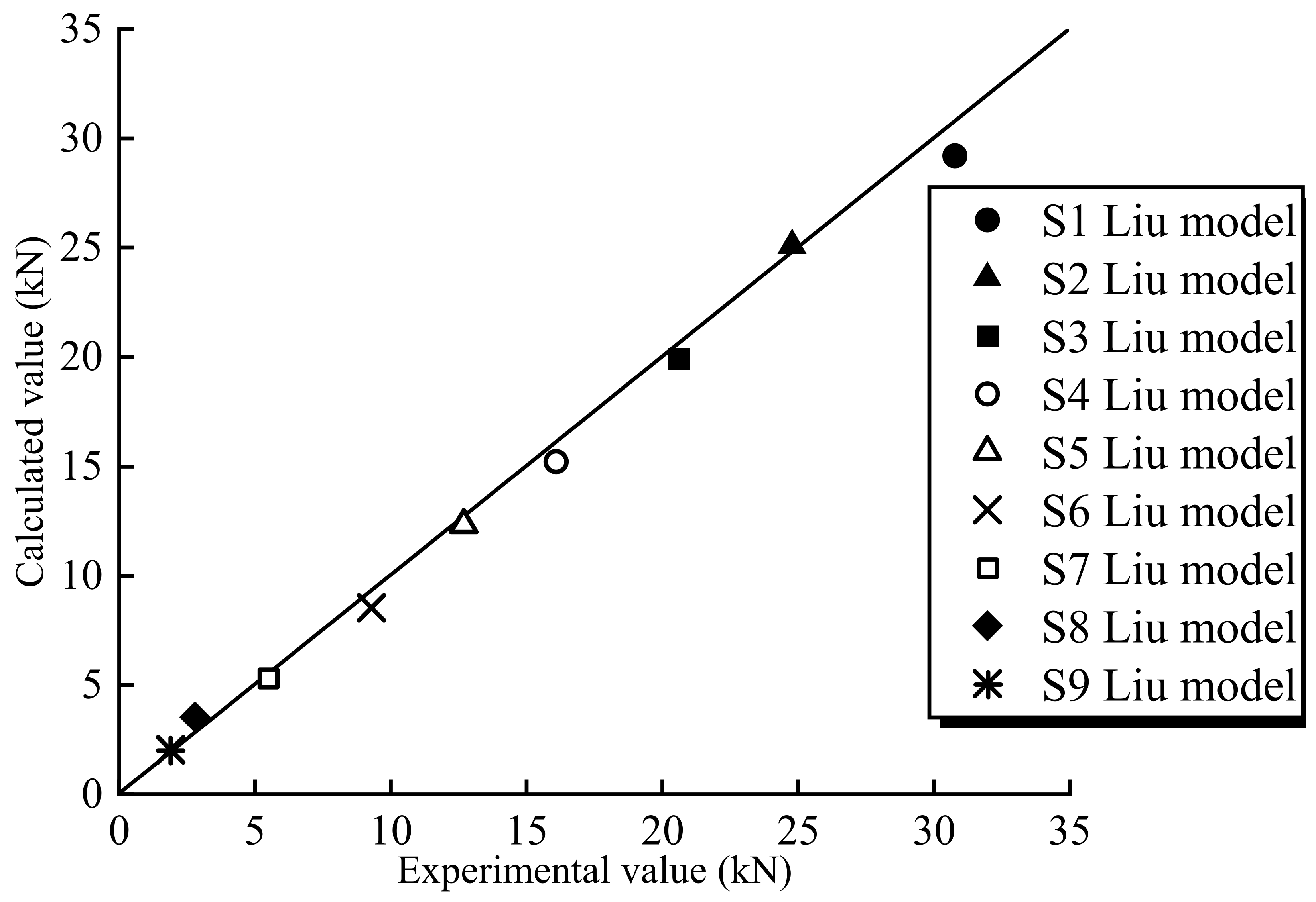
40]. In order to study the failure mode and debonding behavior of the interface between BFRP (basalt fiber reinforced polymer) sheet and structural steel under mixed-mode loading conditions, eighteen specimens with different initial angles were tested in this study. The specimens were designed with different initial angles to ensure that the interface was tested under shear and peeling mixed-mode conditions. Finally, a new calculation method for predicting the bond strength between BFRP sheets and steel under shear-peeling fracture is proposed.

2. Experimental Program

2.1. Specimen Design

A total of 18 specimens with BFRP sheets bonded on two sides were prepared and tested, marked as S1 to S9, respectively. Each specimen was composed of two steel plates with a 5 mm length gap between them. Q345qD-grade steel was used for all specimens. The geometric dimensions and details of the specimens are shown in Figure 1. The dimensions of the two steel plates were 240 × 60 × 10 mm (length × width × thickness) and 200 × 60 × 20 mm (length × width × thickness), respectively. Two different cross-sections of steel plates were prepared to allow for the attachment of an initial angle. The initial angle of the steel plates was machined using a computer numerical control (CNC) machine. By adjusting the length of the pre-unbond region of the plate, the initial angle was manufactured without affecting the step height and the angle value of the steel plate. The initial angles were set as 0°, 2°, 4°, 6°, 8°, 10°, 12°, 15° and 20° corresponding to specimens S1 to S9, respectively. The bi-directional fabrics with a nominal thickness of 0.20 mm were produced by Tianlong Company (Jiangsu, China). The areal density of the commercial BFRP composites is 210 g/m2, and a commercial two-component epoxy adhesive was used as the polymer matrix. The width and length of the BFRP sheets applied in the current experiment were 45.0 mm and 380 mm, respectively. The specimens were prepared with BFRP sheets bonded on both sides of the steel plates. The BFRP sheet was first bonded to the steel plate on one side, and then to the other side within 15 min. One end of the specimen was clipped with an MTS servo-hydraulic testing machine to make sure the interfacial debonding was triggered on the opposite end. Table 1 shows the design parameters of the tested specimens. Two specimens were tested in each load case.
The specimens were prepared according to the following procedure [33]: (1) The adhesive was a two-component modified epoxy resin with a 4:1 weight ratio between glue A and glue B, and it was stirred at 300 rotations per minute for three minutes before application. (2) The surfaces of the steel plates were sandblasted and cleaned with acetone to ensure good bonding between the BFRP sheets and the steel plates. (3) The surfaces of the BFRP sheets were cleaned with acetone before bonding. (4) The adhesive was placed evenly on the surface of the treated steel plates, and the BFRP sheet was pressed to remove excess adhesive and ensure that no air voids existed at the interface. (5) The system was applied to one side, then flipped to the other side, and the operation was repeated. This method ensured that both sides were completed with the same amount of care and attention to detail. (6) There was a 15 min delay between the first and second applications. (7) The specimens with the adhesive were cured for a minimum of seven days at room temperature before testing.

2.2. Material Properties

The adhesive used to bond the BFRP sheet to the steel plate surface was a two-component epoxy adhesive, whose properties are listed in Table 2. The material properties of the adhesive used in the test were provided by the manufacturer. The material properties of the steel plates and the BFRP sheets were tested according to the specifications of GB/T 228.1-2021 [41] and GB/T 3354-1999 [42], respectively. The test results are summarized in Table 3 and Table 4.

2.3. Experimental Setup

The experimental setup and details of the deformation measurement of the specimens are shown in Figure 2. Specimen S1 with an initial angle of 0° was selected as the control specimen for comparison, and a shear debonding failure mode was observed in the tests. Specimens S2 to S9 were subjected to a tensile force to cause a shear-peeling debonding failure at the interface. The specimens were fixed at both ends and then tensioned to failure on a 500 kN capacity MTS servo-hydraulic testing machine at a loading speed of 0.1 mm/min [43]. Each specimen was instrumented with five strain gauges on the BFRP sheet surface on one side. These strain gauges were spaced at intervals of 42.5 mm from the middle gap between the steel plates to the fixed end. Figure 1c shows the locations of the five strain gauges. The sensitivity coefficient of these strain gauges was 2.0 ± 1.0%. The strain gauges on the specimen were numbered Y1 to Y5, respectively.

3. Results and Discussions

3.1. Experimental Phenomena and Failure Modes

The failure modes of the tested specimens are shown in Figure 3. The calculated bond strength was determined using the Liu model [44]. All specimens were subjected to a tensile force until debonding failure occurred on either side. At the initial stage of loading, the load increased roughly linearly with the increase in the relative displacement at the interface. As the load continued to increase, the BFRP sheet debonded from the steel surface at the middle gap of the specimen. Subsequently, the debonding of the BFRP sheet gradually expanded to the end of the specimens. Specimen S1 failed in a pure shear debonding mode, while mixed shear and peeling failure modes occurred in specimens S2 to S9. The failure surfaces of all specimens were failure modes of a combination of BFRP-sheet–adhesive failure and steel-plate–adhesive failure. As the loading increased, the debonding transferred gradually from the steel–adhesive interface to the BFRP-sheet–adhesive interface. In other words, the specimens with a smaller initial angle are more likely to exhibit interfacial debonding between the steel plate and the adhesive. In contrast, the specimens with a larger initial angle are more likely to exhibit peeling at the interface between the BFRP sheet and the adhesive. Nevertheless, for specimens with an initial angle, the debonding progress was caused by a combination of two fracture modes, i.e., peeling and shear debonding modes. The normal force at the interface between BFRP sheets and steel plates increases with the increase in the initial angle. When the initial angle of steel plates is greater than 6°, the specimens are more likely to exhibit peeling at the interface between the BFRP sheet and the adhesive.
Table 5 lists the experimental ultimate load (P) and the calculated ultimate load (Pcal) of the specimens. It can be seen that the ultimate load of the specimen decreases with the increase in the initial angle. The initial angle has a significant influence on the interfacial bonding behavior of the specimens. The accuracy of the predicted strength by the Liu model is reduced gradually with the increase in the angles since the effect of mixed-mode debonding is not considered.

3.2. Load-Displacement Curves

Figure 4 presents the load–displacement relationship of all the specimens. For the specimen without initial angles, the applied load increased to its ultimate value and then decreased until debonding failure. When the initial angle of the specimen was greater than 0°, the load increased to a certain peak value, and then decreased suddenly; afterward, it increased again until failure. The sudden decreases in the load represent the propagation of the delamination of the BFRP sheet caused by peeling. With an increase in the initial angle, the ultimate load of the specimen decreases gradually. Compared with the specimen under pure shear loading at the interface, the ultimate load decreased nearly 50% when the initial angle was 6°. The ultimate load of the specimen with an initial angle of 20° decreased about 94% compared with the base specimen. Therefore, the effect of the initial angle on the ultimate load of the specimen is significant.

3.3. Strain Distribution along the Bond Length

Figure 5 presents the strain distributions observed during the tests. The strain distributions corresponding to the marked points on the load–displacement curves are plotted. As can be seen, when the load was initially applied, the strain response was first observed only at the middle gap of the specimen, and the value increased with increasing load. Macroscopic debonding from the middle gap occurred when the maximum load was reached. When the initial angle was less than 6°, strain increased at the loaded end. As the strain approached the loaded end, a strain plateau was formed. The results from the tests show that the strain generally increased with the load levels and decreased from the gap at the middle of the specimen to the free end of the BFRP sheet. The debonding propagation of the interface can be observed from the strain distribution since there was no strain response in the undamaged regions.

4. Evaluation of Bond Strength

In order to determine the bond strength of the interface between the FRP sheets and the steel without an initial angle, several models have been proposed in the literature [22,28,44,45]. He et al. [22] and Lu et al. [45] proposed a model for calculating the bond shear strength of the CFRP-plate–steel interfaces using an effective bond length, Le. Liu [44] proposed an FRP–steel bond shear capacity model based on the double-lap joint tensile shear tests. Using these selected models, the experimental bond strength was normalized by the calculated bond strength to investigate the effect of the initial angle. The Liu model [44] was selected and used in the present study. The calculation formulae are expressed as follows:
L e = E p t pm 0.5 f v
t pm = ( 1 E p t p 420000 ) t p
P ult = β p β a f v b p L e
β p = 2 b p / b s 1 + b p / b s
β a = 1      , l L e sin π l 2 L e , l < L e
where Le is the effective bond length, Pult is the ultimate load, bp is the width of the BFRP sheet, bs is the width of the sheet plate, tp is the thickness of bonded BFRP sheet, tpm is the effective thickness of the bonded FRP sheet, Ep is the FRP laminate elastic modulus, βp and βa are dimensionless coefficients that reflect the effects of the FRP-to-steel width ratio bp/bc and the bond length l; and fv is the steel-to-steel shearing bonding strength of the adhesive.
The relation between the tensile load P and the calculated tensile load Pcal based on the Liu model is plotted against the peeling angle (tan θ), as shown in Figure 6. It is evident that the tensile load decreases as the peeling angle increases. The relationship between the tensile load ratio and peeling angle can be obtained based on the experimental results by the following equation:
P / P cal = 1.1909 exp 8.281 tan θ
The relationship between the tensile load and peeling angle was studied to evaluate the mixed-mode shear-peeling bond strength. The sheet delaminated as the load proceeded, resulting in a decrease in both the bond length and the peeling angle between the BFRP sheet and the steel surface. The delaminated region is defined as the sheet from the beginning point of the pre-unbond region to the position with a sudden decrease in strain. For example, in specimen S3, the values were determined based on the debonding region of the step height at which the strain gauge was located 43.5 mm from the specimen center when the first sudden drop occurred. Following that, the values were selected step by step, starting at the debonding region and extending to the strain gauge at 86.0 mm. The same method was used for selecting values in the debonding region, which extended to the strain gauge at 128.5 mm and 171.0 mm from the specimen center. Figure 7 illustrates the plots of the proposed equation and the predicted results of the Liu model, which reveals the trends in the shear bond strength curves calculated using the method described above. Experimental results show that the bond length decreased as the BFRP sheet delaminated. As a result, the bond length is shorter than the effective bond length.
For the combined fracture mode, the intersection points in Figure 7 represent the mixed-mode bond strength. Therefore, the corresponding values of P/Pcal can be calculated using the values of tan θ at these intersections. The results are represented in Figure 8. The values of P/Pcal and tan θ are provided in Table 6. For all specimens, the analytical strengths are in good agreement with the experimental results.

5. Conclusions

The failure mode and debonding behavior of the interfaces between the basalt fiber reinforced polymer (BFRP) sheet and structural steel under mixed-mode loading conditions were experimentally studied. The effect of initial angles on the interfacial bond strength was investigated. A predicted method of the shear-peeling bond strength was proposed. Some conclusions can be drawn as follows.
(1) For the specimen without an initial angle, the applied load increased to its ultimate value and then decreased until debonding failure. When the initial angle of the specimen was greater than 0°, the load increased to a certain peak value and then decreased suddenly. Afterward, it increased again until failure.
(2) The specimens with a smaller initial angle were more likely to exhibit a shear debonding failure at the interface between the steel plate and adhesive. In contrast, the specimens with a larger initial angle were more likely to exhibit peeling of the interface.
(3) The ultimate tensile load of the specimen decreased with an increase in the initial angle. The initial angle had a significant influence on the interfacial bonding properties.
(4) A method to predict the interfacial bond strength under mixed-mode loading conditions was proposed. According to the proposed method, the bond strength between the BFRP sheet and the steel under combined shear and peeling fracture conditions can be accurately predicted.

Author Contributions

H.X.: writing—original draft preparation, data curation, formal analysis; D.C.: conceptualization, methodology, resources; Z.T.: formal analysis, investigation; Q.L.: data curation; S.Z.: visualization, validation; J.L.: writing—reviewing and editing; C.S.: methodology, investigation. All authors have read and agreed to the published version of the manuscript.

Funding

This research was funded by the Postgraduate Research & Practice Innovation Program of Jiangsu Province, China (KYCX21_3225 and SJCX22_1747), the Qinglan Project of Yangzhou University, Research and Innovation Team Project of Suqian College (2021TD04), the Fifth Provincial Research Funding Project of “333 High-level Talent Training” in 2020 (BRA2020241), and the Natural Foundation Project of Suqian (K202012), China.

Institutional Review Board Statement

Not applicable.

Informed Consent Statement

Not applicable.

Data Availability Statement

Data is contained within the article.

Conflicts of Interest

The authors declare no conflict of interest.

References

  1. Gardner, L. Stability and design of stainless steel structures-Review and outlook. Thin-Walled Struct. 2019, 141, 208–216. [Google Scholar] [CrossRef]
  2. Wang, F.; Hua, J.; Xue, X.; Ding, Z.; Lyu, Y.; Liu, Q. Low-cycle fatigue performance of bimetallic steel bar considering the effect of inelastic buckling. Constr. Build. Mater. 2022, 351, 128787. [Google Scholar] [CrossRef]
  3. Hua, J.; Xue, X.; Huang, Q.; Shi, Y.; Deng, W. Post-fire performance of high-strength steel plate girders developing post-buckling capacity. J. Build. Eng. 2022, 52, 104442. [Google Scholar] [CrossRef]
  4. Xiang, Y.; Zhou, X.; Ke, K.; Shi, Y.; Xu, L. Experimental research on seismic performance of cold-formed thin-walled steel frames with braced shear panel. Thin-Walled Struct. 2023, 182, 110210. [Google Scholar] [CrossRef]
  5. Bai, Y.; Nguyen, T.C.; Zhao, X.; Al-Mahaidi, R. Environment-assisted degradation of the bond between steel and carborn-fiber-reinforced polymer. J. Mater. Civ. Eng. 2014, 26, 04014054.1–04014054.8. [Google Scholar] [CrossRef]
  6. Bagale, B.; Parvin, A. Fiber-reinforced polymer strengthening of steel beams under static and fatigue loadings. Pract. Period. Struct. Des. Constr. 2021, 26, 04020046. [Google Scholar] [CrossRef]
  7. Bastani, A.; Das, S.; Lawn, D. Rehabilitation of shear deficient steel beams using BFRP fabric. Structures 2019, 19, 349–361. [Google Scholar] [CrossRef]
  8. Lu, Y.; Li, W.; Li, S.; Li, X.; Zhu, T. Study of the tensile properties of CFRP strengthened steel plates. Polymers 2015, 7, 2595–2610. [Google Scholar] [CrossRef]
  9. Shi, J.; Jia, B.; Ren, Y.; Zhang, X.; Luo, J. Study on the interface constitutive relation between carbon fiber fabric and steel. Materials 2020, 13, 3263. [Google Scholar] [CrossRef]
  10. Teng, J.; Yu, T.; Fernando, D. Strengthening of steel structures with fiber-reinforced polymer composites. J. Constr. Steel Res. 2012, 78, 131–143. [Google Scholar] [CrossRef]
  11. Tao, X.; Cao, S.; Zhang, L. Elastic stability of perforated plates strengthened with FRP under uniaxial compression. Appl. Sci. 2017, 7, 1188. [Google Scholar] [CrossRef]
  12. Sundarraja, M.; Sriram, P.; Ganesh, P. Strengthening of hollow square sections under compression using FRP composites. Adv. Mater. Sci. Eng. 2014, 2014, 396597. [Google Scholar] [CrossRef]
  13. Bastani, A.; Das, S.; Kenno, S.Y. Flexural rehabilitation of steel beam with CFRP and BFRP fabrics-A comparative study. Arch. Civ. Mech. Eng. 2019, 19, 871–882. [Google Scholar] [CrossRef]
  14. Kamane, S.K.; Patil, N.K.; Patagundi, B.R. Prediction of twisting performance of steel I beam bonded exteriorly with fiber reinforced polymer sheet by using neural network. Mater. Today Proc. 2021, 43, 514–519. [Google Scholar] [CrossRef]
  15. Zheng, Z.; Du, Y.; Chen, Z.; Li, S.; Niu, J. Experimental and theoretical studies of FRP-steel composite plate under static tensile loading. Constr. Build. Mater. 2021, 271, 121501. [Google Scholar] [CrossRef]
  16. Wang, S.; Stratford, T.; Reynolds, T.P.S. Linear creep of bonded FRP-strengthened metallic structures at warm service temperatures. Constr. Build. Mater. 2021, 283, 122699. [Google Scholar] [CrossRef]
  17. Wang, Y.; Chen, G.; Wan, B.; Han, B.; Ran, J. Axial compressive behavior and confinement mechanism of circular FRP-steel tubed concrete stub columns. Compos. Struct. 2021, 256, 113082. [Google Scholar] [CrossRef]
  18. Pang, Y.; Wu, G.; Wang, H.; Gao, D.; Zhang, P. Bond-slip model of the CFRP-steel interface with the CFRP delamination failure. Compos. Struct. 2021, 256, 113015. [Google Scholar] [CrossRef]
  19. Shen, D.; Li, M.; Liu, C.; Kang, J.; Li, C.; Yang, J. Seismic performance of corroded reinforced concrete beam-column joints repaired with BFRP sheets. Constr. Build. Mater. 2021, 307, 124731. [Google Scholar] [CrossRef]
  20. Zeng, X.; Jiang, S.; Deng, K.; Huang, H.; Cui, E. Seismic performance of circular RC columns strengthened in flexure using NSM reinforcement and externally bonded BFRP sheets. Eng. Struct. 2022, 256, 114033. [Google Scholar] [CrossRef]
  21. Al-Mosawe, A.; Al-Mahaidi, R.; Zhao, X.L. Effect of CFRP properties, on the bond characteristics between steel and CFRP laminate under quasi-static loading. Constr. Build. Mater. 2015, 98, 489–501. [Google Scholar] [CrossRef]
  22. He, J.; Xian, G. Debonding of CFRP-to-steel joint with CFRP delamination. Compos. Struct. 2016, 153, 12–20. [Google Scholar] [CrossRef]
  23. Yuan, C.; Chen, W.; Pham, T.M.; Hao, H. Bond behaviour between hybrid fiber reinforced polymer sheets and concrete. Constr. Build. Mater. 2019, 210, 93–110. [Google Scholar] [CrossRef]
  24. Fawzia, S.; Zhao, X.; AL-Mahaidi, R.; Rizkalla, S. Bond characteristics between CFRP and steel plates in double strap joints. Adv. Steel Constr. 2005, 1, 17–28. [Google Scholar]
  25. Smith, S.T.; Teng, J. Interfacial stresses in plated beams. Eng. Struct. 2001, 23, 857–871. [Google Scholar] [CrossRef]
  26. Doroudi, Y.; Fernando, D.; Nguyen, V.T.; Torres, J.P. Experimental study on CFRP-to-steel bonded interfaces under quasi-static cyclic loading. J. Compos. Constr. 2019, 23, 04019023.1–04019023.13. [Google Scholar] [CrossRef]
  27. Bocciarelli, M.; Colombi, P.; Fava, G.; Fava, G.; Poggi, C. Fatigue performance of tensile steel members strengthened with CFRP plates. Compos. Struct. 2009, 87, 334–343. [Google Scholar] [CrossRef]
  28. Dehghani, E.; Daneshjoo, F.; Aghakouchak, A.A.; Khaji, N. A new bond-slip model for adhesive in CFRP-steel composite systems. Eng. Struct. 2012, 34, 447–454. [Google Scholar] [CrossRef]
  29. Biscaia, H.; Ribeiro, P. A temperature-dependent bond-slip model for CFRP-to-steel joints. Compos. Struct. 2019, 217, 186–205. [Google Scholar] [CrossRef]
  30. Yu, T.; Fernando, D.; Teng, J.; Zhao, X. Experimental study on CFRP-to-steel bonded interfaces. Compos. Part B 2012, 43, 2279–2289. [Google Scholar] [CrossRef]
  31. Wu, C.; Zhao, X.; Chiu, W.; Al-Mahaidi, R.; Duan, W. Effect of fatigue loading on the bond behaviour between UHM CFRP plates and steel plates. Compos. Part B 2013, 50, 344–353. [Google Scholar] [CrossRef]
  32. Wu, T.; Zhao, X.; Duan, W.; Al-Mahaidi, R. Bond characteristics between ultra high modulus CFRP laminates and steel. Thin-Walled Struct. 2012, 51, 147–157. [Google Scholar] [CrossRef]
  33. Golewski, P. Tensile behaviour of double-and triple-adhesive single lap joints made with spot epoxy and double-sided adhesive tape. Materials 2022, 15, 7855. [Google Scholar] [CrossRef]
  34. Jawdhari, A.; Fam, A.; Harik, I. Numerical study on the bond between CFRP rod panels (CRPs) and concrete. Constr. Build. Mater. 2018, 177, 522–534. [Google Scholar] [CrossRef]
  35. Mukhtar, F.M.; Jawdhari, A.; Peiris, A. Mixed-mode FRP-concrete bond failure analysis using a novel test apparatus and 3D nonlinear FEM. J. Compos. Constr. 2022, 26, 04022082. [Google Scholar] [CrossRef]
  36. Altaee, M.J.; Altayee, S.A.; Kadhim, M.; Jawdhari, A.; Majdi, A.; Chabuk, A.; Al-Ansari, N. Evaluation of existing bond-slip relations for CFRP-steel joints and new model for linear and nonlinear adhesives. Adv. Civ. Eng. 2022, 2022, 3673438. [Google Scholar] [CrossRef]
  37. Jawdhari, A.; Peiris, A.; Fam, A.; Harik, I. Evaluation of spliced UHM CFRP strip panels for strengthening steel beams. J. Compos. Constr. 2023, 27, 04022094. [Google Scholar] [CrossRef]
  38. Wang, J. Cohesive zone model of FRP-concrete interface debonding under mixed-mode loading. Int. J. Solids Struct. 2007, 44, 6551–6568. [Google Scholar] [CrossRef]
  39. Zhang, W.; Yan, J. Fatigue properties of shear–peeling debonding between CFRP plates and concrete. Mag. Concr. Res. 2016, 68, 1210–1224. [Google Scholar] [CrossRef]
  40. Ghorbani, M.; Mostofinejad, D.; Hosseini, A. Bond behavior of CFRP sheets attached to concrete through EBR and EBROG joints subject to Mixed-Mode I/II loading. J. Compos. Constr. 2017, 21, 04017034. [Google Scholar] [CrossRef]
  41. GB/T 228.1-2021; Metallic Materials-Tensile Testing—Part 1, Method of Test at Room Temperature. China Architecture & Building Press: Beijing, China, 2021.
  42. GB/T 3354-1999; The Method for Tensile Properties of Oriented Fiber Reinforced Plastics. China Quality and Standards Press: Beijing, China, 1999.
  43. Zhou, H.; Fernando, D.; Torero, J.L.; Torres, J.P.; Maluk, C.; Emberley, R. Bond behavior of CFRP-to-steel bonded joints at mild temperatures: Experimental study. J. Compos. Constr. 2020, 24, 04020070. [Google Scholar] [CrossRef]
  44. Li, C.; Ke, L.; Chen, Z.; He, J.; Luo, N. Experimental study and numerical simulation for bond behavior of interface between CFRP and steel. Acta Mater. Compos. Sin. 2018, 35, 3534–3546. (In Chinese) [Google Scholar]
  45. Lu, X.; Teng, J.; Ye, L.; Jiang, J. Bond-slip models for FRP sheets/plates bonded to concrete. Eng. Struct. 2005, 27, 920–937. [Google Scholar] [CrossRef]
Figure 1. Dimensions and details of test specimens (units: mm): (a) Stereogram; (b) Elevation; (c) Plan.
Polymers 15 02216 g001
Figure 2. Experimental setup and measurement details.
Polymers 15 02216 g002
Figure 3. Failure modes of tested specimens: (a) S1; (b) S2; (c) S3; (d) S4; (e) S5; (f) S6; (g) S7; (h) S8; (i) S9.
Polymers 15 02216 g003aPolymers 15 02216 g003bPolymers 15 02216 g003c
Figure 4. Load–displacement curves of specimens: (a) S2; (b) S3; (c) S4; (d) S5; (e) S6; (f) S7; (g) S8; (h) S9.
Polymers 15 02216 g004aPolymers 15 02216 g004b
Figure 5. Strain distribution along BFRP sheet: (a) S1; (b) S2; (c) S3; (d) S4; (e) S5; (f) S6; (g) S7; (h) S8; (i) S9.
Polymers 15 02216 g005aPolymers 15 02216 g005bPolymers 15 02216 g005cPolymers 15 02216 g005d
Figure 6. Effect of peeling angle on bond strength.
Polymers 15 02216 g006
Figure 7. Evaluation of combined fracture bond strength for specimens: (a) S1; (b) S2; (c) S3; (d) S4; (e) S5; (f) S6; (g) S7; (h) S8; (i) S9.
Polymers 15 02216 g007aPolymers 15 02216 g007b
Figure 8. Relationship between experiment value P and calculated value Pcal.
Polymers 15 02216 g008
Table 1. Parameters of test specimens.
SpecimenS1S2S3S4S5S6S7S8S9
Initial angle θ10°12°15°20°
Pre-unbond length (mm)0.0143.271.545.635.628.423.518.713.7
For each load case, 2 replicates were produced and tested.
Table 2. Material properties of adhesive.
Tensile Strength (MPa)Flexural Strength (MPa)Elongation at Break (%)Compressive Strength (MPa)Steel-to-Steel Joint (MPa)Elastic Modulus (MPa)
35.045.01.467.017.33010.0
Table 3. BFRP sheet properties.
Thickness (mm)Elastic Modulus (GPa)Fiber Diameter (μm)Tensile Strength (MPa)
0.285.08.02400.0
Table 4. Steel properties.
Steel TypeThickness (mm)Yield Strength (MPa)Ultimate Strength (MPa)Elastic Modulus (GPa)
Q345qD10 and 20397.5585.4210.0
Table 5. Test results of the specimens.
SpecimenInitial Angle θUltimate Load P(kN)Liu ModelP/Pcal (kN)
Calculated Ultimate Load Pcal (kN)
S130.829.21.05
S224.80.86
S320.60.68
S416.10.52
S512.70.42
S610°9.30.29
S712°5.50.18
S815°2.80.12
S920°1.90.07
Table 6. Tested and predicted results.
SpecimenInitial Angle θExperimental Value P (kN)tan θP/PcalPredicted Value P (kN)
Equation (6)Liu ModelEquation (6)Liu Model
S130.80.0251.191.0534.829.2
S224.80.0420.890.8626.025.1
S320.60.0670.670.6819.519.9
S416.10.0980.500.5214.615.2
S512.70.1250.370.4210.912.3
S610°9.30.1690.280.298.18.5
S712°5.50.2280.200.186.05.3
S815°2.80.2720.130.123.83.5
S920°1.90.3380.060.071.72.0
Disclaimer/Publisher’s Note: The statements, opinions and data contained in all publications are solely those of the individual author(s) and contributor(s) and not of MDPI and/or the editor(s). MDPI and/or the editor(s) disclaim responsibility for any injury to people or property resulting from any ideas, methods, instructions or products referred to in the content.

