Article

Ballistic Response of a Glass Fiber Composite for Two Levels of Threat

by
George Ghiocel Ojoc
1,
Larisa Chiper Titire
1,
Cristian Munteniță
1,
Cătălin Pîrvu
2,
Simona Sandu
3 and
Lorena Deleanu
1,*
1
Faculty of Engineering, “Dunarea de Jos” University, 800008 Galati, Romania
2
National Institute for Aero-Space Research (INCAS) “Elie Carafoli”, 061126 Bucharest, Romania
3
Center for Research and Innovation for CBRN Defense and Ecology, 02512 Bucharest, Romania
*
Author to whom correspondence should be addressed.
Polymers 2023, 15(4), 1039; https://doi.org/10.3390/polym15041039
Submission received: 6 February 2023 / Revised: 16 February 2023 / Accepted: 17 February 2023 / Published: 19 February 2023

Abstract

:
This paper presents the behavior of composite panels based on glass fiber unidirectional fabrics and a bi-component epoxy resin under ballistic impacts that characterize two threat levels: FB2 and FB3, according to EN 1523:2004. The tested panels had characteristics kept in narrow ranges: thickness 18.26 ± 0.22 mm, mass ratio fabrics/panel 0.788 ± 0.015, surface density 27.51 ± 0.26 kg/m2. After testing the panels, the failure mechanisms of the panel were evidenced by scanning electron microscopy and photographs. Here the authors present a finite-element model at meso scale that was used for evaluating if the composite, initially tested at level FB2 (9 mm FMJ, v0 = 375 m/s), could withstand the higher level of impact, FB3 (projectile type 0.357 Magnum and impact velocity of v0 = 433 m/s). Simulation was performed in Explicit Dynamics (Ansys), keeping the same target but changing the projectile for the two different levels of threat. The results of the simulation were encouraging for making tests at level FB3, indicating the importance of alternating actual tests with simulations in order to achieve better protection with reduced surface weight. The simulation illustrated differences in impact duration and number of layers broken on the panel for each level. Validation of the model was based on the number of broken layers and the dimension of the delamination zone between the last two layers. Scanning electron microscopy was used for identifying failure mechanisms at the micro and meso scale. We found that damage to the composite was intensively dependent on impact velocity, this being quantitatively evaluated using the number of layers broken, the effect of delamination on separating layers and the deformation of the last layer.

Graphical Abstract

1. Introduction

Composites with glass fiber fabrics, bonded with high-quality resins, are used for equipment protection, especially for vehicles and enclosed spaces that are exposed to projectiles [1,2,3,4,5,6,7]. The variables involved in the fabrication of such composites are numerous and their initial design requires dedicated documentation for, e.g., the quality of the glass fiber, types of fabrics, yarn and sublayer architecture, resin and technological aspects and thermal treatment [8,9,10].
Non-woven fabrics, also known as unidirectional fabrics, gained a market almost half a century ago as substitutes for woven or knitted textiles. Among their recognized advantages are lower price and rapid processing of composites [11], but in time, this type of fabric became evidentially adequate for particular applications especially, including ballistic protection systems [12,13]. Non-woven fabrics have, as base elements, high-quality fibers in terms of structure, length and mechanical characteristics. The yarns formed by these fibers are held together with auxiliary stitching yarns or/and very thin polymer foils that have a very low influence on the mechanical characteristics of the main fibers [8,12]. The fibers can be natural, synthetic (polymers) or from special resources (glass, carbon, ceramics), but polymeric, carbon and glass fibers are designated in designing components of high performance. Today, for ballistic protection, composites based on unidirectional fibers have become of interest, and research has intensified in particular for body armors and vehicles. There are numerous combinations of fabrics and resins and with the risk of the applications being high, tests are imperatively required on the final products. Of course, in order to limit the number of final tests, because they are expensive [14,15], research is generally performed on simplified samples and simulations using numerical solutions (as finite element method or smoothed-particle hydrodynamics method [16]).
Satkar A. R. et al. [17] reported the ballistic performances of a hybrid composite of three layers of glass fiber fabric and two layers of carbon fiber fabric in an epoxy matrix, based on a numerical simulation with ANSYS-Explicit Dynamic, for several impact velocities (400 m/s, 450 m/s and 500 m/s) and different fabric combinations. The results indicate that glass fiber fabric has better behavior but higher surface density.
Many reports deal with woven glass or polymeric fabrics for ballistic protection, but those for unidirectional or multiaxial fabrics are less common [18]. The importance of sub-layer architecture (meaning the layers and their orientations as prepreg, as supplied by the fabric producers) was pointed out in [19]; the prepreg formed using quadriaxial fabric (0°/90°/45°/−45°), namely LFT SB1plus, in a panel of 12 layers had a smaller BFS (back face signature [20]) compared to a panel of 24 layers of prepreg with biaxial fabric (0°/90°), namely LFT SB1, even if surface density and thickness were close.
The ballistic limit of E-glass/epoxy composite is higher than that of carbon/epoxy composite. The energy absorption in E-glass/epoxy composite is produced by fiber deformation and their tensile failures, whereas the energy absorption in carbon/epoxy composite includes less residual yarn deformation, but more shear plugging [21,22].
Ansari and Chakrabarti [18] present a numerical model for stratified layers of glass fibers, using anisotropic properties for the target, but the model was run without friction; therefore, it differs from reality. The coefficient of friction was set to 0.22 for textiles in [23] and Zhou Y. et al. [24] presented a model with friction (with the same friction coefficient COF = 0.22 between yarns), noting that the energy dissipated by friction was proportional to the impact velocity of the projectile for the studied range of velocities. Signetti S. et al. [25] used a model with the same friction law for the sliding contact between the projectile and the target layers, depending on relative sliding between nodes, taking into account both dynamic and static values. Ingles S. et al. [26] considered to have an optimum for the value of the friction coefficient in order to determine the maximum of the absorbed energy in a ballistic process when modeling fabrics with aramid fibers. Vescovini A. et al. [27] considered the same friction coefficient in a model with layers made of aramid fibers and glass fibers.
Mohan S. and Velu S. [28] proposed an analytical model to study the impact process of differently shaped projectiles penetrating into a unidirectional glass fiber reinforced cross ply with laminate with 8 layers and 7.1 mm thickness, but their experimental work evaluated the correspondence between model and test for low impact velocities (approx. 100 m/s), not for setting a protective design.
Ma D. et al. [29] presented a study with a model at meso scale for the panel (composed of layers with defined properties, based on testing the composite at different strain rates), having similar values for the strength limits of a layer and the same delamination model but with lower values. In 2022, Ma D. et al. [30] discussed several finite element models, at macro and meso levels, comparing the simulation results with the experimental ones. The models varied the mechanical characteristics as a function of strain rate and the accuracy of the residual velocity and damage aspects was improved by introducing the appropriate strain rate effect on the elasticity modulus and the strain at break.
Karthick P. and Ramajeyathilagam K. [31] published a numerical model for hybrid composites under impact (layers of fabrics with glass, carbon and aramid fibers, in hybrid sequences). To simulate the ballistic impact behavior of a glass fiber composite plate numerically, a MAT 54 enhanced composite damage material model was used, with Chang–Chang failure criteria, available in LS DYNA, but friction was not included.
Continuum and meso scale model response under 153 m/s velocity impact on a single woven layer was presented by Meyer C. S. et al. [32]. Their meso scale model included accurate fabric geometry and fiber volume fraction, rate-dependent matrix behavior, and important damage mechanisms including tow–tow delamination, tow pullout and frictional sliding. They selected μ = 0.5 for the friction coefficient in the delaminated zones and concluded that the meso scale model with appropriate values for mechanical characteristics depending on strain rate was closer to the experimental results, reporting the use of this model for a single threat.
This paper applies a relatively new design procedure [33] for armor development, studying ballistic performances of a composite made of quadriaxial glass fiber fabrics and high-quality epoxy resin. The first design solution was produced and tested in order to assess a threat level (FB2) and, based on these results and the literature, a finite element model at meso scale was elaborated, predicting that the solution could face a more dangerous impact (FB3), a conclusion supported by tests performed under requirements for this higher level of threat. The levels were those in the standard SR EN 1522:2004. Initially, a campaign of tests was performed for different thicknesses (number of layers of the same fabric) [34] for FB2, but the better response of the 24-layer composite to the FB2 threat suggested that it could be used for higher protection levels. Tests with projectile and parameters characterizing the FB3 level were performed and they indicate that the 24-layer composite is adequate for FB3 protection.

2. Materials and Methods

The composite had 24 layers of glass fiber fabric. The fabric was also layered into four unidirectional substrates (0°/+45°/90°/−45°), which gives the authors the opportunity to suggest that the fabric has quasi-isotropic behavior. The trade name is 1200 g/m2 quadriaxial glass cloth (0°/+45°/90°/−45°), with the code WTVQX1200-1 E-glass, Q1200E10Q [35,36]. Table 1 details the architecture of the fabric reinforcement.
Table 2 presents the average values of elemental composition for the core of the glass fibers (9 measurements on different fibers’ cross sections) and the jacket (5 measurements). Figure 1 shows the measurement points (indicated by a red cross) for two of these measurements. The differences in composition of the core and jacket of the glass fibers were small; thus, the fibers could be considered as having a homogenous composition as a whole body. For these fabrics, the boron content was higher than those attributed in the literature to high-resistance glass fibers of class D, E or S, which covers a range of 1% to 22%. This content should be attributed to the particular sourcing location of the raw materials. Boron decreases glass thermal expansion and not only increases resistance to vibration, strength, chemical resistance and long-life use, but also increases resistance to high temperatures and thermal shock.
After reviewing the documentation for resins used in fiberglass composites [21,37],, the two-component resin Biresin® CR82 with hardener CH80-2 (Table 2) was selected from the products offered by the manufacturer Sika Group [38]. The mixing ratio must be followed accurately, as given in the resin data sheet, for optimal results. The final values for thermal and mechanical properties depend on the heat treatment after natural aging. The authors respected the producer’s heat treatment recommendations, as mentioned in [39], heating the panels with a rate of ca. 0.2 °C/minute, keeping the panels for 6 h at 60 °C (under the glass transition temperature and heat distortion temperature of fully cured neat resin) and then cooling them at a rate of ca. 0.5 °C/minute.
Biresin® CR82 with hardener CH80-2, presented in Table 3, is a two-component epoxy resin for individual, manual lay-up, layer or vacuum forming and winding, especially for applications where a heat treatment temperature ≥75 °C cannot be applied. It can be used in marine and general composites for industry. The material and processing enclosure are recommended to have temperatures from 18 °C to 35 °C [39]. Using Biresin® CH80-2 hardener, the composite can be removed from the mold at room temperature. Table 3 shows mechanical and thermal properties of the already formed and heat-treated resin, and it is observed that using the hardener CH80-2, a fairly high tensile limit was obtained.
Because of the panel dimensions (300 mm × 300 mm) and the individual pressing of each panel, the mixture of the two resin components was obtained in small quantities of 800 g of CR82 resin and 200 g of CH80-2 hardener for one mixture in order to keep it adequate to be laid up.
A layer of extraction wax was applied on the mold surface and the plywood sheets to ensure that the composite came off the mold more easily. CIREX CP 10 is an extraction wax (Airétec supplier) used for polyester and epoxy resins. The laying-up process consists of spreading the resin mixture on each layer with the help of a brush. The ballistic protective panels were kept in the press under load for at least 24 h.
Table 4 presents the characteristics of five fabricated panels of 24 layers, their average values and their standard deviations.
Considering the panel volume of 0.0016434 m3 and the volume of glass fiber fabrics as the ratio between the glass fiber fabric mass and an approximate density of 2300–2500 kg/m3 (as for glass fibers), a theoretical volume ratio of fibers/composite is 0.6–0.64, indicating the good quality of this composite. Key C. T. et al. [5] reported a 50–60% fiber volume fraction and 50–70% is also given in [37] due to statistical aspects of the processing of composites. Abdulmajeed A. A. et al. [40] reported a volume fraction of 51–57% for glass fiber for designed composites destinated for medical use.
Figure 2 presents a Gantt diagram for manufacturing a set of five panels made of 24 layers of glass fiber fabrics, pointing out natural aging and the heat treatment. It is important to know the processing time for the final products.
Tests were performed at the Center for Research and Innovation for CBRN Defense and Ecology (Bucharest, Romania) and there the impact velocity was measured. Table 5 presents the characteristics of the levels FB2 and FB3. Each panel was hit in three points, with 120 mm between two points. The average measured values of the impact velocity were 375 m/s for FB2, meaning −6.25% of the average value in standard, and 433 m/s for FB3, meaning + 8.25% of the average value in standard. The impact velocity was noted as v0 and was measured using a projectile velocity measuring system, the Öehler 43 chronograph. The bullet hit from a distance of 5 m (normal conditions, [15]).

3. Results of the Simulation

3.1. The Model

Impact models are usually run at one of the following levels:
  • Macro, with the target being one body, made of a single equivalent material, used especially for metallic shields [41];
  • Meso, implying the layers as a continuous body with equivalent properties determined experimentally [27] and paying attention to modeling the bonding between them, being applied the cohesive zone model [42,43,44,45,46,47,48,49], as the designer wanted to have the thickness of the entire panel as small as possible; in this group, we can include fabrics modeled with yarns. This model is difficult to calibrate, taking into account the statistical response of such a multitude of bodies;
  • Micro, when analyzing the behavior of a bundle of fibers under impact [50,51]; the big differences between dimensions of the fiber cross section and the projectile dimensions influence the model behavior.
The modeled system contained the panel and the projectile. The panel was the same, but the projectile was different: one case used a 9 mm FMJ (full metal jacket) and the other case used a Magnum 0.357. Every bullet was made of two bodies with “perfect bonded” connection. The panel was composed of 24 layers. The element size and the discretization method are of importance, but in Ansys Explicit Dynamics the engineers must compromise between the element size, their number and the running time [52,53]. Figure 3a,b, presents the dimensions of the projectiles as parametric inputs and their meshing, after analyzing the drawings in [41,54,55,56].
For both projectiles, a tetrahedral network with at least two elements on the jacket thickness was used, obtained from an initial discretization, over which a mesh with three spheres of influence with increasing radii was added, the smallest sphere having the finest mesh (Figure 3), in order to have a relatively controlled growth of elements. For the first sphere, the element size was 0.35 mm, for the next sphere, it was 0.45 mm and for the largest one, it was 0.55 mm (Figure 3c,d).
The panel had a surface of 120 mm × 120 mm. The actual panel was 300 mm × 300 mm, allowing for three hits at a distance of 120 mm, forming an equilateral triangle, as required by the standard EN 1523:2004 Windows, doors, shutters and blinds. Bullet resistance. Test method. The simulation was run for only one hit on a smaller surface, but large enough to cause delamination.
The initial condition was the projectile velocity, considered here as v0 = 375 m/s for the 9 mm FMJ projectile and v0 = 433 m/s for the 0.357 Magnum projectile, these being the average measured values for the test campaign.
The 3D model was run as a half system, considering the symmetry plane of the system through the center of the squared panel and the longitudinal section of the projectile axis.
The limit conditions involved the lateral fixing of the panel. Each layer of the plate was embedded (fixed) on the lateral side surface of the layer.
For diminishing the running time, the bullet was very close to the panel, the distance between its tip and the panel being 0.258 mm.
The connection between layers was “bonded”, with “breakable’’ separating condition (the nodes being separated if certain values for the normal and shear stresses were overpassed, these being 100 MPa for traction and 70 MPa for shear, values characterizing the resin used for attaching the layers in panels).

3.2. Material Models of the Bodies Involved in the Model

In the run cases, the Johnson–Cook model was used for the core material (a lead alloy) and the jacket material (a brass alloy), based on the experimental data obtained by [57,58,59] (Table 6). Each layer of the panel had the mechanical characteristics in Table 6. Ou Y. et al. [1] reported high values of tensile strength limits for glass fiber yarn (around 1800 MPa) and values up to 800 MPa for the tested composite, depending on the strain rate, especially for passing from a lower (1/600 s−1) to a greater strain rate (158 s−1), and the resin had mechanical properties lower than those characterizing the resin model used in this study.
Based on the mentioned references and [60,61,62], the authors introduced a bilinear hardening model for the layer, here considered a homogenous and isotropic material, as different orientations of yarns on fabric sub-layers tend create properties in a narrower range [63,64].
Based on references [49,65], a cohesive zone model (CMZ) with zero thickness was introduced between the layers [53], the name in Explicit Dynamics commands for modeling the CZM being “Bilinear for interface delamination” and the failure criterion being set as “Fracture energies based debonding” for crack opening mode I. The parameters characterizing the cohesive zone model are given in Table 7.

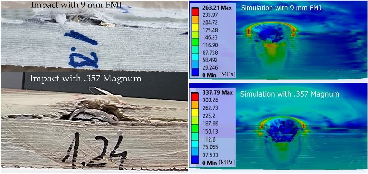
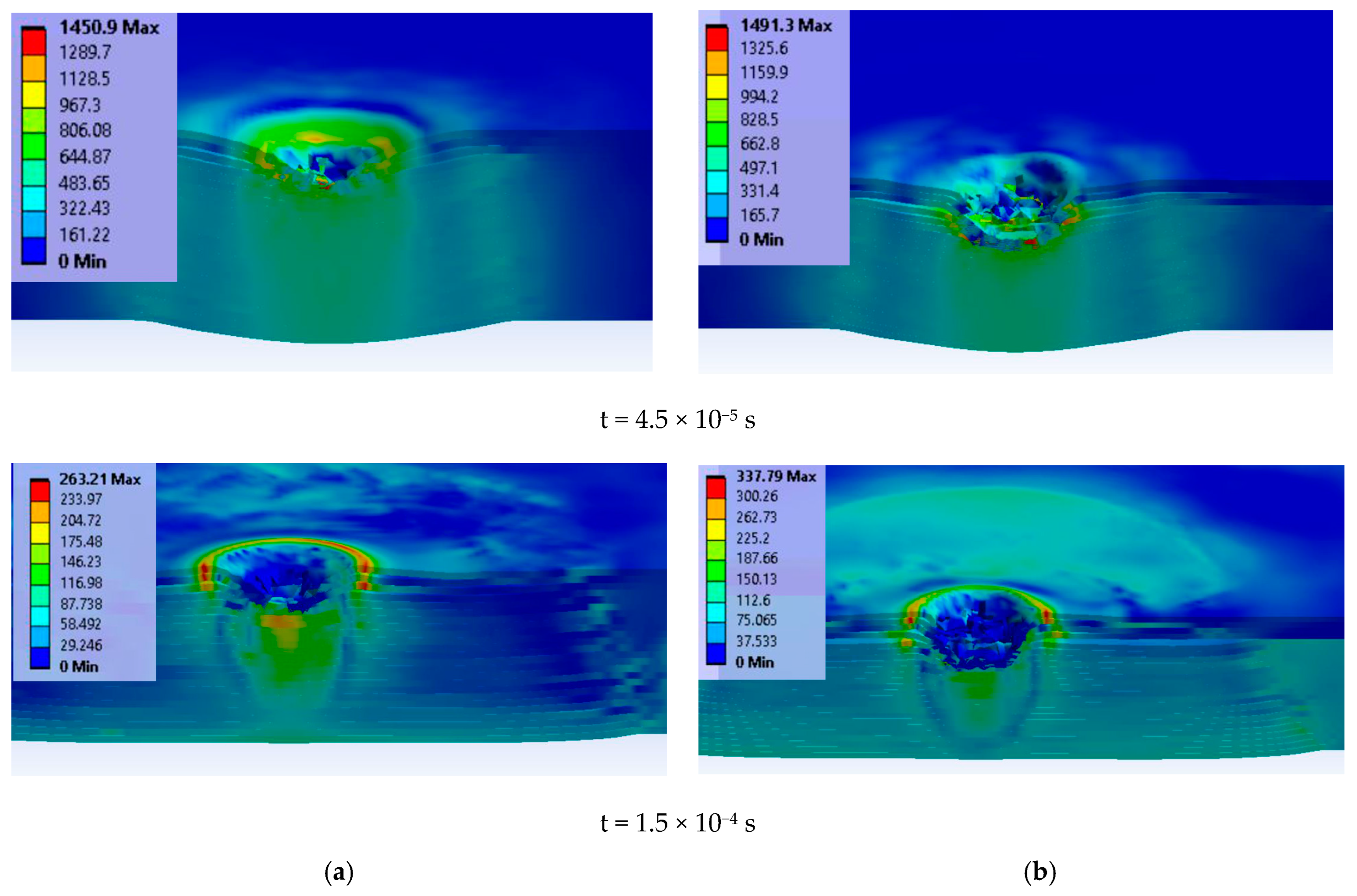
3.3. Analysis of the Simulation Results

The first moment of the simulation was t = 7.5 × 10⁻⁶ s for both cases (one case for impact velocity v0 = 375 m/s with the 9 mm FMJ and the second case for v0 = 433 m/s with the 0.357 Magnum).
Due to the network meshing and the size of the elements, a slight asymmetry in layer rupture and equivalent stress distribution was possible, something that could also happen in an actual impact, as the material and geometry are not perfect. Thus, it was necessary to see where the rupture on each layer occurred and how the stress concentrators developed. The projectiles in both cases were allocated as transparent in order to better “see” the layer in the contact zone.
Figure 4 presents an example of von Mises stress distribution for the cross section of layer 2 at moment t = 1.5 × 10⁻⁴ s (the end of the simulation) indicating how the distance along the cross section of the panel is measured: 0 is at the left end of the layer, 60 mm is at the symmetry axis through the projectile and panel and 120 mm is at the right end of the layer.
Each graph in Figure 5 presents the von Mises stress distribution on the first layers involved in the failure process and the last layer. It was noticed that, at the end of the simulation, for v0 = 375 m/s, four layers were broken, and for v0 = 433 m/s, six layers were damaged. The plot succession shows at which moment each layer was broken (zero stress), the higher velocity being responsible for a more rapid and extended failure (in number of layers and affected volume in the target). Additionally, taking into account delamination, this failure process was more intense and enlarged on the analyzed cross length of the layers for the higher impact velocity. This is also evidenced by the photos in Figure 9b,d), where the delamination is visible as a lighter color compared to the general color of the panels.
At the first moment of the simulation, t = 7.5 × 10⁻⁶ s, the maximum values of von Mises stress were smaller for the 9 mm FMJ projectile (lower impact velocity of v0 = 375 m/s), but for the 0.357 Magnum, the maximum value was noticed on the second layer, close to the strength limit of the layer model, and there were stress values that announced possible delamination larger than that in the first case. The last layer was characterized by stress values under the layer yield limit for both cases, higher for the case with higher impact velocity. The load of the composite was more rapid and more intense for the impact with the 0.357 Magnum projectile. At t = 2.25 × 10⁻⁵ s, the second layer was broken (zero value for von Mises stress) under the 0.357 Magnum bullet, but the 9 mm FMJ one produced no break in the layers.
At t = 4.5 × 10⁻⁵ s, only two layers failed at impact velocity v0 = 375 m/s, but for v0 = 433 m/s, the first five layers were already broken. The 24th layer was stressed but under the yield limit.
The last moment of simulation, t = 1.5 × 10⁴ s, evidenced low values of von Mises stress for all layers in both cases, lower than the yield limit of the layer material model.
Figure 6 presents layer images in the first moment of the simulation (t = 7.5 × 10⁶ s). The impact with the blunt projectile (0.357 Magnum) and higher velocity produced higher values of equivalent stress on each layer (only the first six layers are presented here). One may notice that the equivalent stress distributions have asymmetrical aspects, even if the model is based on symmetrical geometry. This is due to the meshing net and this happens in actual impact, too, as there are not perfect shapes and the actual materials also have structural and composition differences that could generate asymmetry in material loading.
This analysis should be correlated with the images obtained at the same moments, as the break of a certain layer could be initiated in a zone not included in the analyzed path. See Figure 7, layer 6 of the panel hit by the 0.357 Magnum bullet.
For the impact with the 9 mm FMJ projectile, the affected (stressed) zone had lower values for each layer compared to the impact produced by the other projectile. At t = 7.5 × 10⁻⁶ s, the biggest difference between the maximum values of von Mises stress was found on layer 4 (almost 50%). For the impact with the 0.357 Magnum projectile, layer 2 was the most stressed and layer 1 had a semi-circular zone of high stress, the other layers having small concentrated zones.
Figure 7 presents von Mises stress distributions on each layer at the moment t = 4.5 × 10⁻⁵ s for impact with the 9 mm FMJ at v0 = 375 m/s (left column) and impact with the 0.357 Magnum at v0 = 433 m/s (right column).
After this moment, there were no broken layers. The layer fragmentation was more intense for the higher impact velocity and these small fragments could be seen in SEM images on the last not-broken layer (see Figure 12a,d).
Figure 8 presents a cross section in the panel for two moments: at t = 4.5 × 10⁻⁵ s, there are similar local high values of von Mises stress, but delamination is more pronounced and the deformation on the last layer is greater for the higher impact velocity; at the last moment of the simulation, t = 1.5 × 10⁻⁴ s, the peripheries of delamination are well differentiated.
Comparing the images of the panels at t = 4.5 × 10⁻⁵ s to those at t = 1.5 × 10⁻⁴ s (the simulation’s end), one may notice that even if there were no more breaks in the layers until the end of simulation, the delamination continued. Small fragments, detached from superior failed layers, embedded (pressed) into the following layers. At this final moment, values for von Mises stress were lower than the yield limit of the glass fiber yarns and anterior delamination allowed for the bending of the layers around the direct impact zone.
The authors selected as the criterion for model validation the number of broken layers, and Table 8 presents this characteristic for both cases, the model and the actual tests.

4. Analysis of the Failure Mechanisms after Actual Tests

Failure mechanisms should be discussed for each scale level of the target [66]:
  • Micro, including glass fibers and resin damage;
  • Meso, here including delamination and failure of the projectile;
  • Macro, including qualification of the composite and partial or total penetration, evidenced by photos taken of the entire panel or large areas or sections of it.
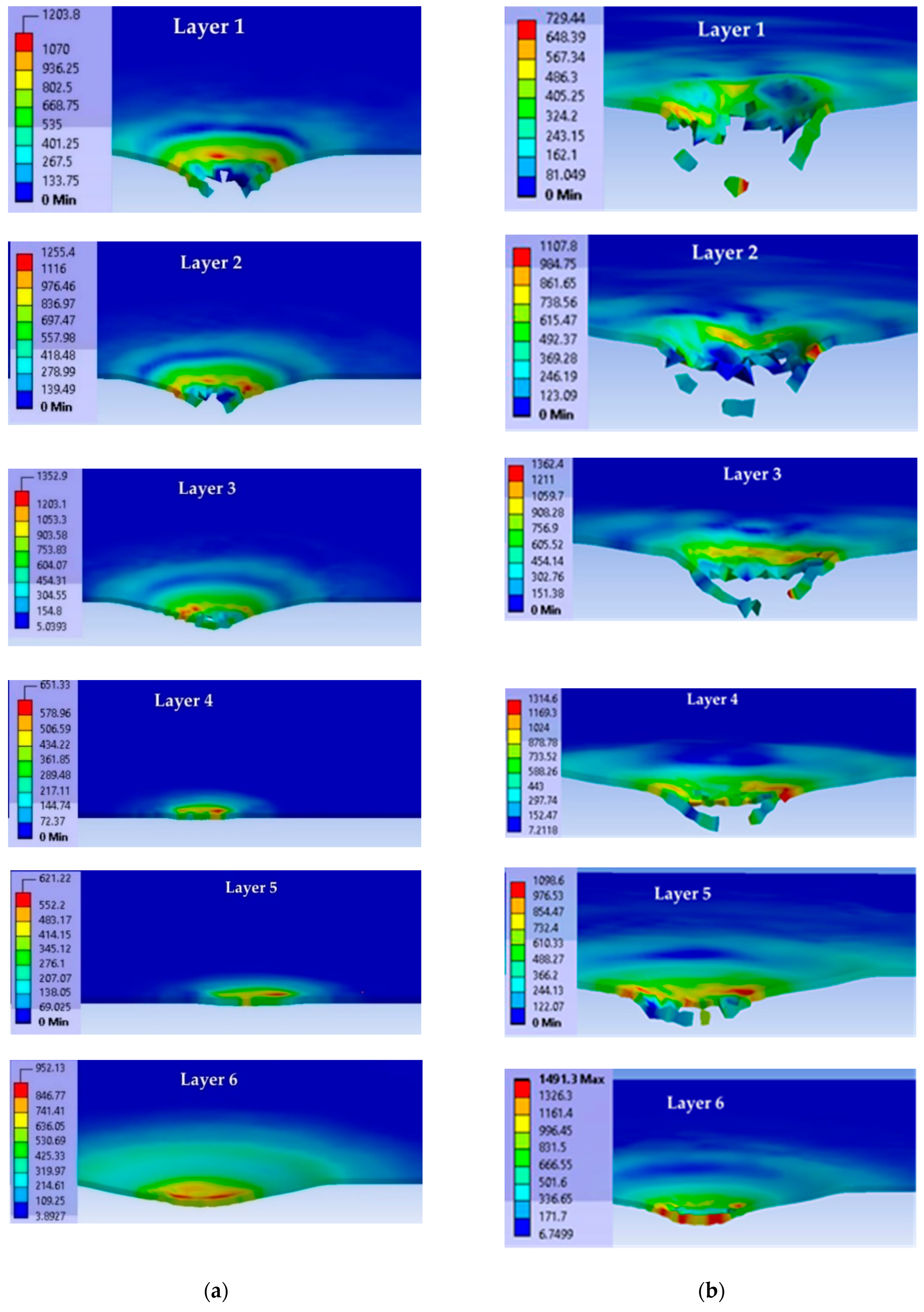
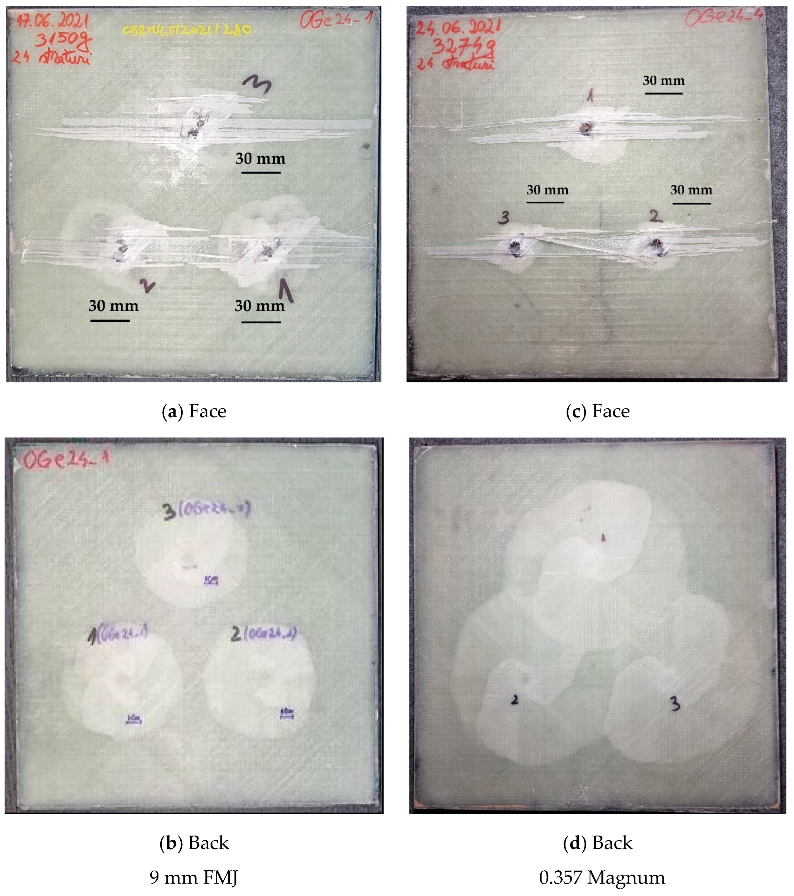
Figure 9 presents macro photos of the panels. The projectiles’ arrests have similar aspects all the three fires. It means that the panel is able to endure multiple hits at a close vicinity (the distance between fires was 120 mm).
A delamination of several yarns on the first layer of glass fibers that does not affect the integrity of the panel is visible. Delamination is visible on the panel back, with smaller circular zones for the lower impact velocity and overlapping, almost circular zones for the other impact velocity. The shape and color tones of the delamination suggest a process that advanced unevenly between layers. This is more visible in a cross section of the panel, obtained via high-speed cuts in dry conditions.
The characteristics of the cross-sections indicate the following (Figure 10): the projectile with lower impact velocity and round head was flattened, but also rebounded to raise up the first broken layers (Figure 10a); meanwhile, the pointed projectile with higher impact velocity (Figure 10b) penetrated more layers and the raising of the broken layers was smaller, but the delamination was larger and very visible on many layers beneath the layers that stopped the projectile. Figure 11 presents how the penetration volume was cut in order to be examined with use of the scanning electron microscope. The surfaces of interest (the impacted face and the cross section) were gold-coated to obtain high-quality images.
Figure 12 shows SEM images of the panel after impact with the 9 mm FMJ (ac) and the 0.357 Magnum (df):
(a)
Top view of the penetration hole produced by the 9 mm FMJ;
(b)
Detail of the surface that the projectile was stopped on (fragments of the projectile are not in this image, but there are glass fiber fragments);
(c)
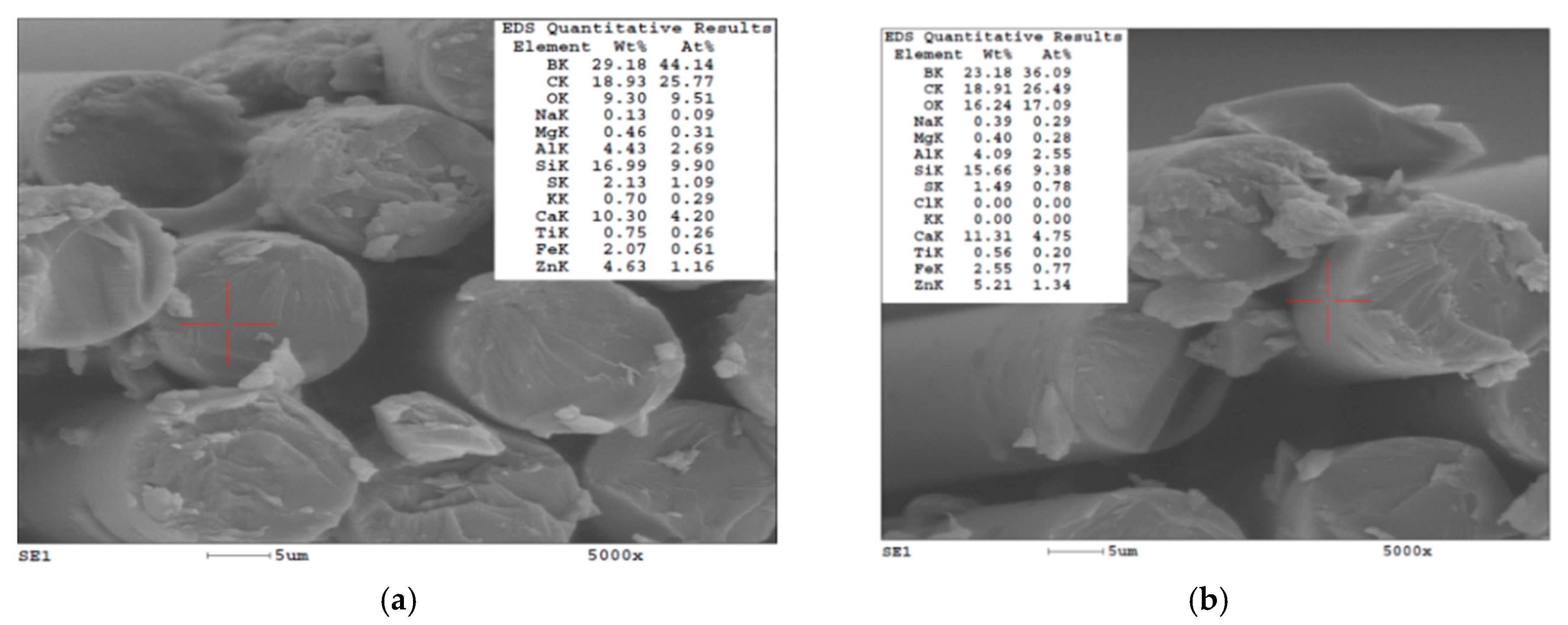
Shear cut of a glass fiber (up), typically for impacted glass fibers, meaning a cut surface almost perpendicular to the fiber axis;
(d)
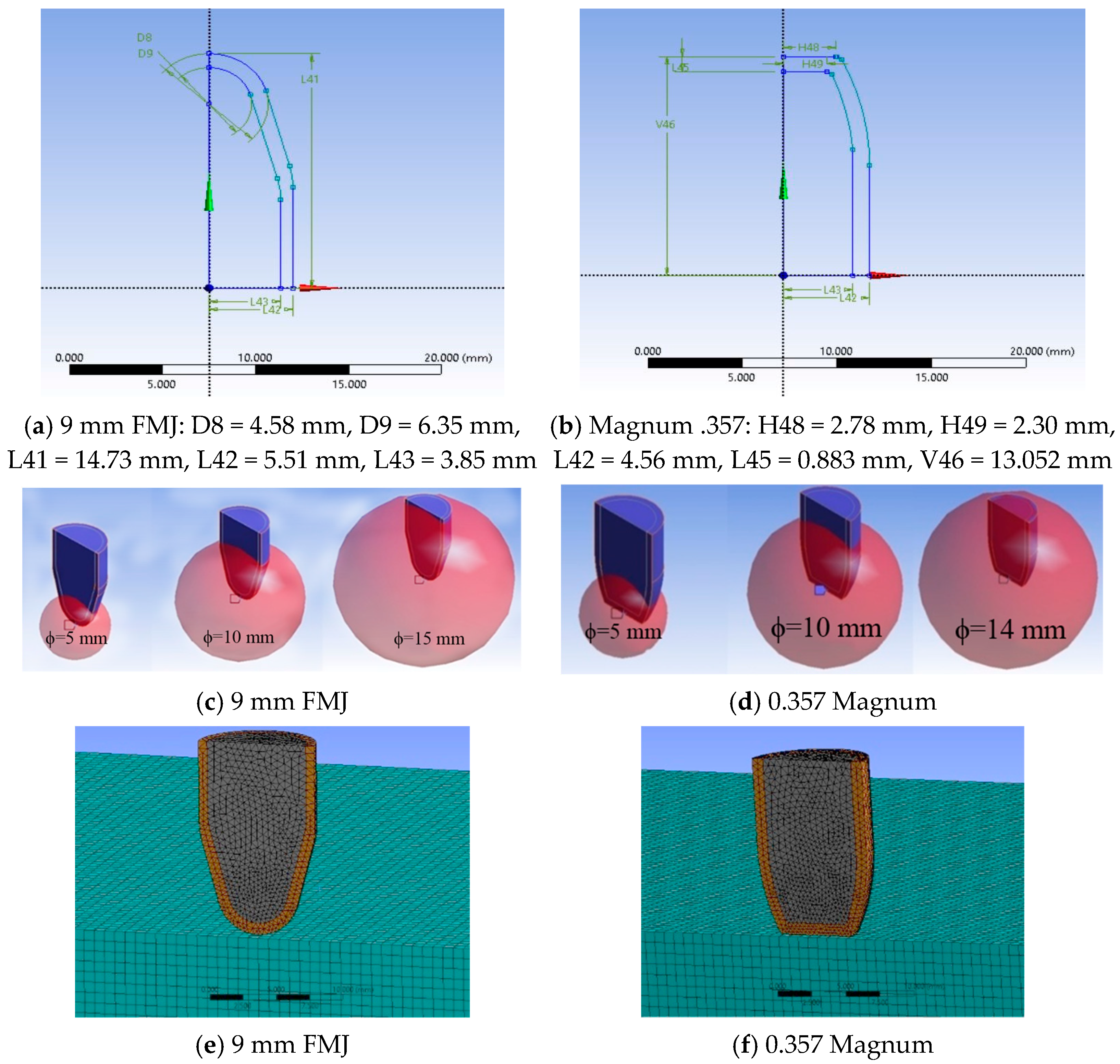
Top view of the penetration hole produced by the 0.357 Magnum. On the bottom the flattened projectile is visible, less fragmented compared to the 9 mm FMJ;
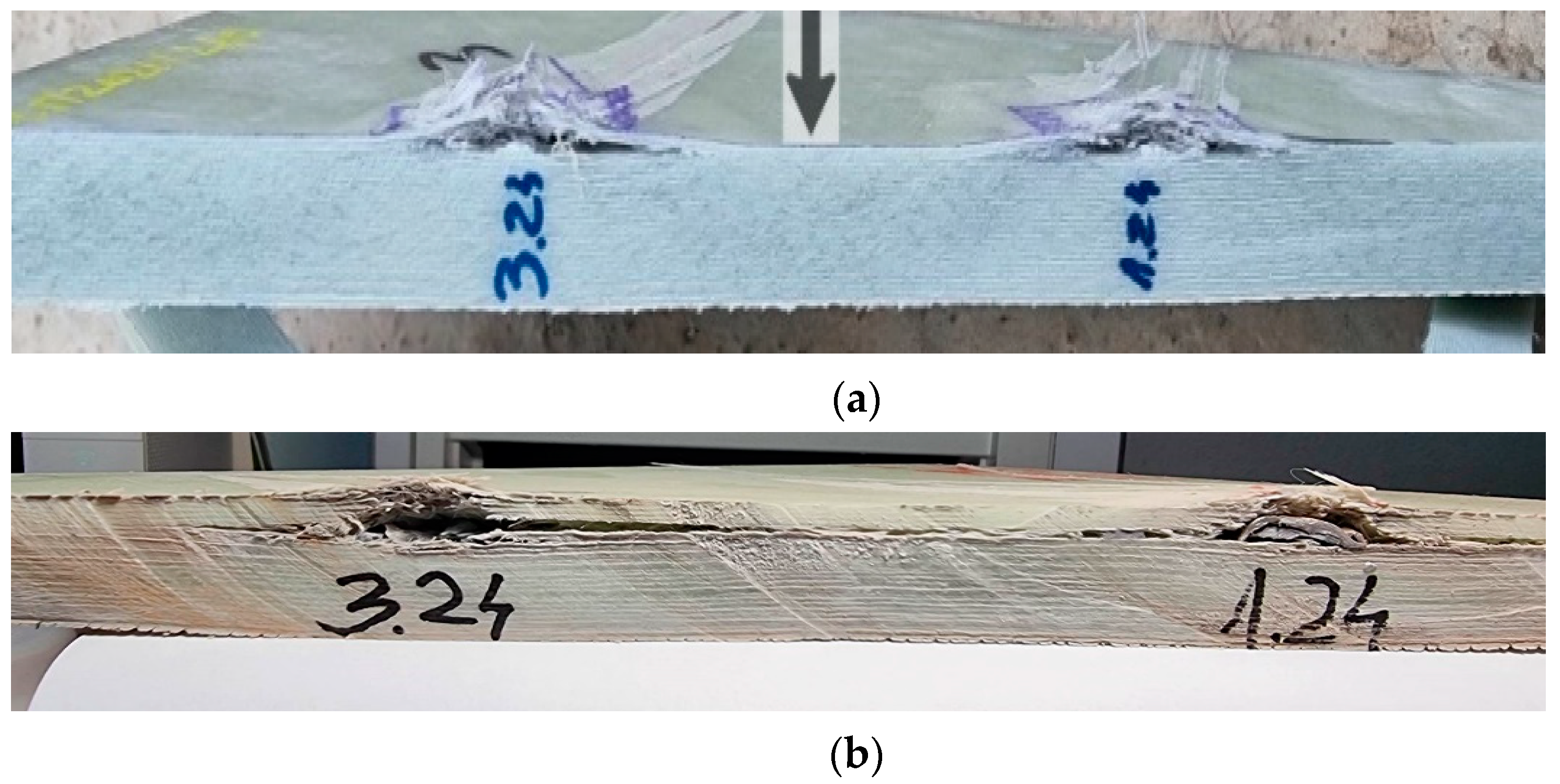
(e)
Detail in cross section, with flattened projectile and hole, not very cylindrical due to the different orientation of the yarns in each sub-layer;
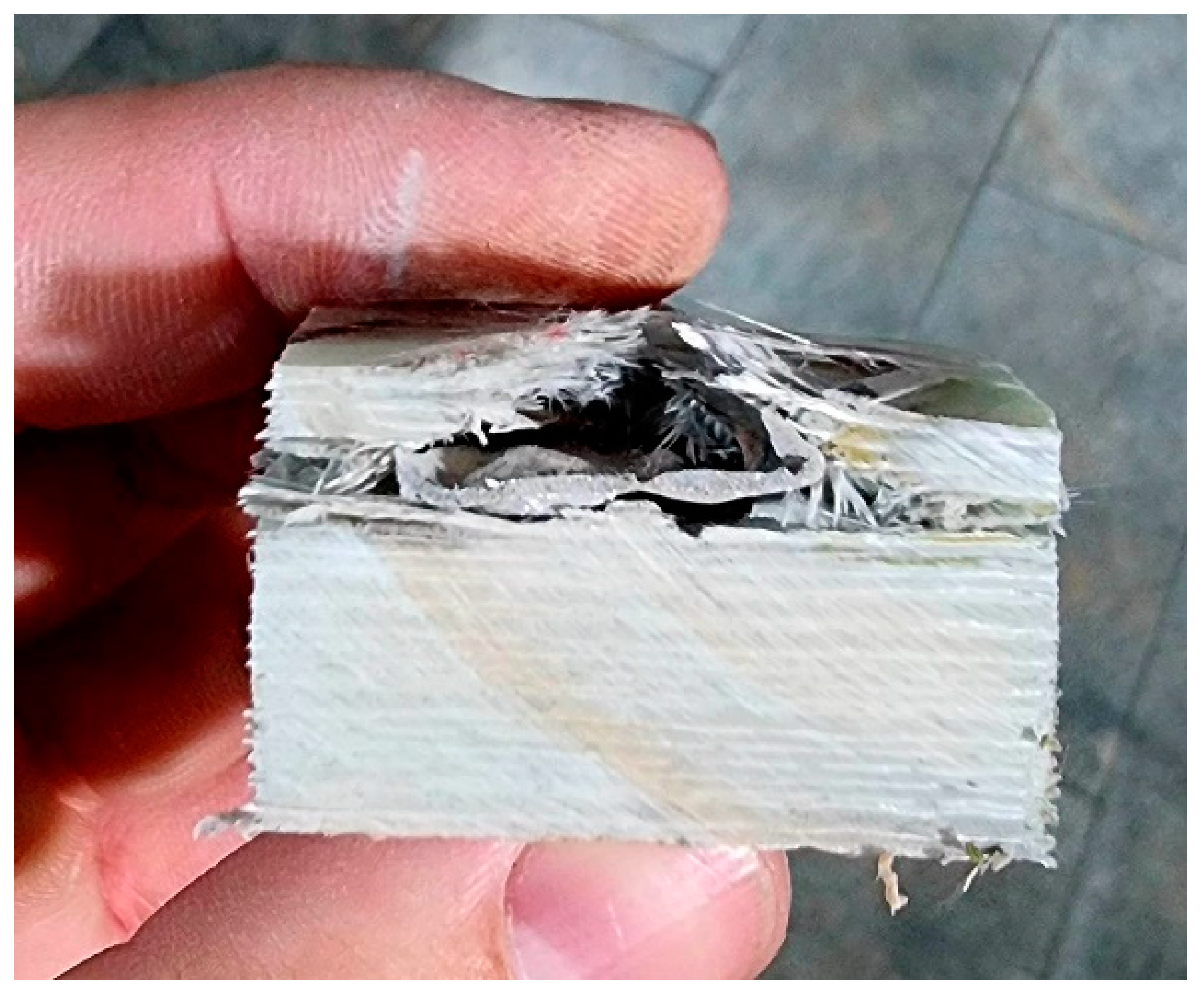
(f)
Detail of cut fibers and the aspect of delamination, revealing the detaching of the fibers of different orientation and other fibers remaining in the matrix.
Nunes S. G. et al. [67] presented experimental results on panels made of aramid fibers with similar projectiles for an impact velocity of 430 m/s (0.357 Magnum), obtaining zero residual velocity with an area density of 17.61 kg/m2 but no “reserve” on the panel thickness, meaning that the last layers were damaged; their model, with many similarities to this one, presented a virtual residual velocity of 195 m/s. Adding 25–30% of the aramid fabric thickness of 14.5 mm, this became 18.125–18.85 mm. Additionally, in this study, the BFS (back face signature), which is a request for body armor [20], was not given, as this composite is destinated for vehicle or equipment protection.
For the glass fiber panel (with 24 layers of quadriaxial fabrics) of 24.15 mm hit by the same projectile, the unbroken layers numbered 19, meaning too much “reserve”; this means that the range of thickness or the number of layers should be investigated for panels with less than 24 layers in order to optimize this panel. It could also be tested (virtually first) at a higher level.

5. Conclusions

This numerical and experimental study shows that alternating simulation of an impact at meso scale (target made of layers) using a finite element method and actual tests could be advantageous for designing ballistic protective composites, as elaborated by the authors, based on quadriaxial glass fiber fabrics and epoxy resin. Analyzing the behavior of the composite against a projectile 9 mm FMJ (v0 = 375 m/s), in actual and virtual tests, the finite element model presumed that the same composite would behave reliably for another threat (0.357 Magnum, v0 = 433 m/s). Tests performed for this level confirmed that the manufactured composite endured this threat as well. This designing method for systems with high risk may be used successfully for impact-protective systems.
The damage to a composite is intensively dependent on impact velocity and projectile type (shape, materials and mass), this being quantitatively evaluable by the number of broken layers, the layers’ delamination and the deformation of the last layer.
Simulation allows for virtually separating the impact stages on such a composite as well as evaluating the response of the same composite under different threat levels, based on already performed tests for only one threat, in order to optimize the design of the panel (especially diminishing surface density while keeping the same safety requirements) or recommend the same system for facing a higher threat level. The simulation results, validated by initial tests, are useful for reducing test costs, optimizing a certain protective system by diminishing its surface density or thickness while fulfilling the safety requirements, or recommending the system for a higher level of protection (as was the case in this study). Of course, the acceptance of a composite system for a higher level of protection requires actual standardized tests.
This study presents the behavior of the same panel—a composite based on quadriaxial glass fiber fabrics and an epoxy resin—under ballistic impacts that characterized two threat levels: FB2 and FB3, according to EN 1523:2004. We presented a model at meso scale that was used for evaluating if the composite, initially tested at level FB2 (9 mm FMJ, v0 = 375 m/s) could face a superior level of impact, FB3 (0.357 Magnum and v0 = 433 m/s). The simulation was performed using Explicit Dynamics (Ansys), keeping the same target but changing the projectile as required for the two different levels of threat. The results of the simulation are encouraging for testing at level FB3, indicating the importance of alternating actual tests with simulations in order to obtain better protection with reduced surface weight. The simulation indicated differences in impact duration and number of layers broken in the panel for each tested level. Validation of the model was performed for the FB2 test based on the number of broken layers and the dimension of the delamination zone between the last layers. Scanning electron microscopy was used for identifying the failure mechanisms at micro scale.

Author Contributions

Conceptualization, G.G.O. and C.P.; methodology, L.D. and S.S.; software, G.G.O. and L.C.T.; validation, L.D. and C.P.; formal analysis, C.P. and L.D.; investigation, G.G.O.; resources, C.P.; writing—original draft preparation, C.P., C.M. and G.G.O.; writing—review and editing, L.D.; visualization, C.M., G.G.O. and S.S.; supervision, L.D. All authors have read and agreed to the published version of the manuscript.

Funding

This research received no external funding.

Data Availability Statement

All data having references could be publicly accessed.

Conflicts of Interest

The authors declare no conflict of interest.

References

  1. Ou, Y.; Zhu, D.; Zhang, H.; Huang, L.; Yao, Y.; Li, G.; Mobasher, B. Mechanical Characterization of the Tensile Properties of Glass Fiber and Its Reinforced Polymer (GFRP) Composite under Varying Strain Rates and Temperatures. Polymers 2016, 8, 196. [Google Scholar] [CrossRef] [Green Version]
  2. Stanciu, M.D.; Draghicescu, H.T.; Rosca, I.C. Mechanical Properties of GFRPs Exposed to Tensile, Compression and Tensile–Tensile Cyclic Tests. Polymers 2021, 13, 898. [Google Scholar] [CrossRef]
  3. Reddy, R.S.P.; Reddy, S.T.; Madhu, V.; Gogia, A.K.; Rao, V.K. Behavior of E-glass composite laminates under ballistic impact. Mater. Des. 2015, 84, 79–86. [Google Scholar] [CrossRef]
  4. Czech, K.; Oliwa, R.; Krajewski, D.; Bulanda, K.; Oleksy, M.; Budzik, G.; Mazurkow, A. Hybrid Polymer Composites Used in the Arms Industry: A Review. Materials 2021, 14, 3047. [Google Scholar] [CrossRef]
  5. Key, C.T.; Alexander, C.S.; Harstad, E.N.; Schumacher, S.C. Dynamic Shock Response of an S2 Glass/SC15 Epoxy Woven Fabric Composite Material System. AIP Conf. Proc. 2018, 1979, 110006. [Google Scholar] [CrossRef]
  6. Pavlovic, A.; Fragassa, C. Investigating the resistance of reinforced barriers to high velocity projectiles. Eng. Struct. 2018, 174, 384–395. [Google Scholar] [CrossRef]
  7. Pai, A.; Kini, C.R.; Shenoy, S.B. Development of materials and structures for shielding applications against Blast and Ballistic impact: A Detailed Review. Thin-Walled Struct. 2022, 179, 109664. [Google Scholar] [CrossRef]
  8. Bilisik, K.; Karaduman, N.S.; Bilisik, N.E. Fiber Architectures for Composite Applications. In Fibrous and Textile Materials for Composite Applications. Textile Science and Clothing Technology; Rana, S., Fangueiro, R., Eds.; Springer: Singapore, 2016; pp. 75–134. [Google Scholar] [CrossRef]
  9. Alagumalai, V.; Shanmugam, V.; Balasubramanian, N.K.; Krishnamoorthy, Y.; Ganesan, V.; Försth, M.; Sas, G.; Berto, F.; Chanda, A.; Das, O. Impact Response and Damage Tolerance of Hybrid Glass/Kevlar-Fibre Epoxy Structural, Composites. Polymers 2021, 13, 2591. [Google Scholar] [CrossRef]
  10. Onyechi Pius, C.; Edelugo, S.O.; Ihueze Chukwutoo, C.; Obuka Nnaemeka, S.P.; Chukwumuanya Okechukwu, E. High Velocity Impact Response Evaluation of a Glass Fibre Reinforced Polymer (GFRP) Composite—Amour Body. Int. J. Energy Eng. 2013, 3, 242–255. [Google Scholar] [CrossRef]
  11. Zhai, Z.; Jiang, B.; Drummer, D. Strain rate-dependent mechanical behavior of quasi-unidirectional E-glass fabric reinforced polypropylene composites under off-axis tensile loading. Polym. Test. 2018, 69, 276–285. [Google Scholar] [CrossRef]
  12. Kalebek, N.A.; Babaarslan, O. Fiber Selection for the Production of Nonwovens. In Non-Woven Fabrics; Jeon, H., Ed.; InTech: London, UK, 2016; pp. 1–32. [Google Scholar] [CrossRef]
  13. Aghbash, S.A.; Breite, C.; Mehdikhani, M.; Swolfs, Y. Longitudinal debonding in unidirectional fibre-reinforced composites: Numerical analysis of the effect of interfa-cial properties. Compos. Sci. Technol. 2022, 218, 109117. [Google Scholar] [CrossRef]
  14. NIJ Standard 0108.01; Ballistic Resistant Protective Materials. National Institute of Justice: Washington, DC, USA, 1985.
  15. SR EN 1523-2004; Windows, Doors, Shutters and Blinds—Bullet Resistance—Test Method. ASRO: Bucharest, Romania, 2004.
  16. Nastasescu, V.; Barsan, G. Metoda Particulelor Libere in Analiza Numerica a Mediilor Continue; AGIR Publishing House: Bucharest, Romania, 2015. (In Romanian) [Google Scholar]
  17. Satkar, A.R.; Mache, A.; Kulkarni, A. Numerical investigation on perforation resistance of glass-carbon/epoxy hybrid composite laminate under ballistic impact. Mater. Today Proc. 2022, 59, 734–741. [Google Scholar] [CrossRef]
  18. Ansari, M.M.; Chakrabarti, A. Ballistic performance of unidirectional glass fiber laminated composite plate under normal and oblique impact, 11th International Symposium on Plasticity and Impact Mechanics. Proc. Eng. 2017, 173, 161–168. [Google Scholar] [CrossRef]
  19. Pirvu, C. Contribution on Experimental and Numerical Studying Ballistic Protection Packages Made of Aramid Fibers. PhD Thesis, “Dunarea de Jos” University of Galati, Galati, Romania, 2015. [Google Scholar]
  20. NIJ Standard 0101.07; Ballistic Resistance of Body Armor, National Institute of Justice. National Institute of Justice: Washington, DC, USA, January 2018.
  21. Naik, N.K.; Shrirao, P. Composite structures under ballistic impact. Compos. Struct. 2004, 66, 579–590. [Google Scholar] [CrossRef]
  22. Bilisik, K. Two-dimensional (2D) fabrics and three-dimensional (3D) preforms for ballistic and stabbing protection: A review. Text. Res. J. 2017, 87, 2275–2304. [Google Scholar] [CrossRef]
  23. Briscoe, B.J.; Motamedi, F. Role of Interfacial Friction and Lubrication in Yarn and Fabric Mechanics. Text. Res. J. 1990, 60, 697–708. [Google Scholar] [CrossRef]
  24. Zhou, Y.; Yao, W.; Zhang, Z.; Sun, M.; Xiong, Z.; Lin, Y.; Wang, D.; Wang, M. The effect of cumulative damage on the ballistic performance of plain weaves. Compos. Struct. 2022, 297, 115978. [Google Scholar] [CrossRef]
  25. Signetti, S.; Ryu, S.; Pugno, M.N. Impact mechanics of multilayer composite armors: Analytical modeling, FEM numerical simulation, and ballistic experiments. Compos. Struct. 2022, 297, 115916. [Google Scholar] [CrossRef]
  26. Ingle, S.; Chandra, S.Y.; Anirban, G.; Sushil, M. Effect of material properties on ballistic energy absorption of woven fabrics subjected to different levels of inter-yarn friction. Compos. Struct. 2021, 266, 113824. [Google Scholar] [CrossRef]
  27. Vescovini, A.; Balen, L.; Scazzosi, R.; da Silva, A.A.X.; Amico, S.C.; Giglio, M.; Manes, A. Numerical investigation on the hybridization effect in inter-ply S2-glass and aramid woven composites subjected to ballistic impacts. Compos. Struct. 2021, 276, 114506. [Google Scholar] [CrossRef]
  28. Mohan, S.; Velu, S. Ballistic impact behaviour of unidirectional fibre reinforced composites. Int. J. Impact Eng. 2014, 63, 164–176. [Google Scholar] [CrossRef]
  29. Ma, D.; Manes, A.; Campos Amico, S.; Giglio, M. Ballistic strain-rate-dependent material modelling of glass-fibre woven composite based on the prediction of a meso-heterogeneous approach. Compos. Struct. 2019, 216, 187–200. [Google Scholar] [CrossRef]
  30. Ma, D.; Wang, Z.; Giglio, M.; Amico, S.C.; Manes, A. Influence of strain-rate related parameters on the simulation of ballistic impact in woven composites. Compos. Struct. 2022, 300, 116142. [Google Scholar] [CrossRef]
  31. Karthick, P.; Ramajeyathilagam, K. Numerical study on ballistic impact behavior of hybrid composites. Mater. Today: Proc. 2022, 59, 995–1003. [Google Scholar] [CrossRef]
  32. Meyer, C.S.; O’Brien, D.J.; Haque, B.Z.G.; Gillespie, J.W. Mesoscale modeling of ballistic impact experiments on a single layer of plain weave composite. Compos. Part B 2022, 235, 109753. [Google Scholar] [CrossRef]
  33. National Research Council. Opportunities in Protection Materials Science and Technology for Future Army Applications; The National Academies Press: Washington, DC, USA, 2011; Available online: http://nap.edu/13157 (accessed on 12 January 2022). [CrossRef]
  34. Ojoc, G.G. A Theoretical and Experimental Study of Ballistic Protection Packages Made of Glass Fibers. PhD Thesis, “Dunarea de Jos” University of Galati, Galati, Romania, 2022. [Google Scholar]
  35. Glass. Available online: https://www.castrocompositesshop.com/en/63-glass (accessed on 22 February 2022).
  36. 1200 g/m2 Quadriaxial Stitched Glass Fabric (0°/+45°/90°/−45°), 127 cm Wide. Available online: https://www.castrocompositesshop.com/en/fibre-reinforcements/1204-1200-gm2-quadriaxial-stitched-glass-fabric-0%C2%BA45%C2%BA90%C2%BA-45%C2%BA-127-cm-wide.html (accessed on 22 February 2022).
  37. Gibson, R. Principles of Composite Material Mechanics, 2nd ed.; CRC Press: Boca Raton, FL, USA, 2007. [Google Scholar]
  38. Sika Group. About Us. Available online: https://www.sika.com/en/home.html. (accessed on 3 October 2021).
  39. Biresin® CR82. Composite Resin System. Available online: https://industry.sika.com/dms/getdocument.get/93a3a9b1-7291-47ce-8ca7-18ae3f458043/Biresin-CR82-New.pdf. (accessed on 4 October 2020).
  40. Abdulmajeed, A.A.; Närhia, T.O.; Vallittu, P.K.; Lassila, L.V. The effect of high fiber fraction on some mechanical properties of unidirectional glass fiber-reinforced composite. Dent. Mater. 2011, 27, 313–321. [Google Scholar] [CrossRef]
  41. Masri, R.; Ryan, S. Ballistic limit predictions of non-identical layered targets perforated in ductile hole formation. Int. J. Impact Eng. 2023, 171, 104391. [Google Scholar] [CrossRef]
  42. Jinescu, V.V. Application in Mechanical Engineering of Principle of Critical Energy; Lambert Academic Publishing: Saarbrucken, Germany, 2015. [Google Scholar]
  43. Jinescu, V.V.; Nicolof, V.I.; Chelu, A.; Manea, S.E. Calculation of the local critical state taking into account the deterioration and the residual stresses. Int. J. Eng. Sci. 2017, 2, 9–21. [Google Scholar] [CrossRef]
  44. Cohesive Zone Material (CZM) Model, Release 18.2 © ANSYS, Inc. Available online: https://www.mm.bme.hu/~gyebro/files/ans_help_v182/ans_thry/thy_mat11.html (accessed on 22 February 2022).
  45. Li, S.; Thouless, M.D.; Waas, A.M.; Schroeder, J.A.; Zavattieri, P.D. Use of a cohesive-zone model to analyze the fracture of a fiber-reinforced polymer–matrix composite. Compos. Sci. Technol. 2005, 65, 537–549. [Google Scholar] [CrossRef]
  46. Harper, P.W.; Hallett, S.R. Cohesive zone length in numerical simulations of composite delamination. Eng. Fract. Mech. 2008, 75, 4774–4792. [Google Scholar] [CrossRef] [Green Version]
  47. Harper, P.W.; Sun, L.; Hallett, S.R. A study on the influence of cohesive zone interface element strength parameters on mixed mode behaviour. Composites Part A 2012, 43, 722–734. [Google Scholar] [CrossRef] [Green Version]
  48. Joki, R.K.; Grytten, F.; Hayman, B.; Sørensen, B.F. Determination of a cohesive law for delamination modelling—Accounting for variation in crack opening and stress state across the test specimen width. Compos. Sci. Technol. 2016, 128, 49–57. [Google Scholar] [CrossRef] [Green Version]
  49. Chowdhury, U.; Wu, X.-F. Cohesive zone modeling of the elastoplastic and failure behavior of polymer nanoclay composites. J. Compos. Sci. 2021, 5, 131. [Google Scholar] [CrossRef]
  50. Sockalingam, S. Transverse Impact of Ballistic Fibers and Yarns—Fiber Length-Scale Finite Element Modeling and Experiments. Ph.D. Thesis, University of Delaware, Newark, DE, USA, 2016. Available online: https://udspace.udel.edu/handle/19716/19972 (accessed on 22 February 2022).
  51. Mishnaevsky, L., Jr. Micromechanical modelling of wind turbine blade materials. In Advances in Wind Turbine Blade Design and Materials; Brøndsted, P., Nijssen, R.P.L., Eds.; Woodhead Publishing Limited: Cambridge, UK, 2013; pp. 298–324. [Google Scholar] [CrossRef]
  52. Totolici Rusu, V.; Ojoc, G.G.; Pirvu, C.; Deleanu, L. Influence of element size in a case of impact simulation. Mech. Test. Diagn. 2021, 10, 24–29. Available online: https://www.gup.ugal.ro/ugaljournals/index.php/mtd/article/view/406 (accessed on 22 February 2022). [CrossRef]
  53. ANSYS Explicit Dynamics Analysis Guide; ANSYS, Inc.: Canonsburg, PA, USA, 2021.
  54. Buyuk, M.; Kan, C.-D.S.; Bedewi, N.E.; Durmus, A.; Ulku, S. Moving Beyong the Finite Elements, a Comparison between the Finite Element Methods and Meshless Methods for a Ballistic Impact Simulation. In Proceedings of the 8th International LS-Dyna Users Conference, DynaLook, Detroit, MI, USA, 2–4 May 2004. [Google Scholar]
  55. Scazzosi, R.; Manesa, A.; Giglio, M. An Enhanced Material Model for the Simulation of High-Velocity Impact on Fiber-Reinforced Composites. Procedia Struct. Integr. 2019, 24, 53–65. [Google Scholar] [CrossRef]
  56. Wiśniewski, A.; Gmitrzuk, M. Validation of numerical model of the Twaron CT709 ballistic fabric. In Proceedings of the 27th International Symposium on Ballistics, Freiburg, Germany, 22–26 April 2013; Ballistic Publishing: Adelaide, Australia, 2013; Volume 2, pp. 1535–1544. [Google Scholar]
  57. Børvik, T.; Dey, S.; Clausen, A.H. Perforation resistance of five different high-strength steel plates subjected to small-arms projectiles. Int. J. Impact Eng. 2009, 36, 948–964. [Google Scholar] [CrossRef]
  58. Giglio, M.; Gilioli, A.; Manes, A.; Peroni, L.; Scapin, M. Investigation about the influence of the mechanical properties of lead. EPJ Web Conf. 2012, 26, 04010. [Google Scholar] [CrossRef] [Green Version]
  59. Peroni, L.; Scapin, M.; Fichera, C.; Manes, A.; Giglio, M. Mechanical properties at high strain-rate of lead core and brass jacket of a NATO 7.62 mm ball bullet in numerical simulations of ballistic impacts. Proc. DYMAT 2012, 26, 01060. [Google Scholar] [CrossRef] [Green Version]
  60. Naresh, K.; Shankar, K.; Rao, B.S.; Velmurugan, R. Effect of high strain rate on glass fiber reinforced epoxy laminated composites. Composites Part B 2016, 100, 125–135. [Google Scholar] [CrossRef]
  61. Kumar, M.; Naik, N.K. Prediction of mechanical behavior of composites under high strain rate tensile loading. Mech. Res. Commun. 2018, 90, 1–7. [Google Scholar] [CrossRef]
  62. Tao, Y.; Chen, H.; Yao, K.; Lei, H.; Pei, Y.; Fang, D. Experimental and theoretical studies on inter-fiber failure of unidirectional polymer-matrix composites under different strain rates. Int. J. Solids Struct. 2017, 113–114, 37–46. [Google Scholar] [CrossRef]
  63. Wang, Y.; Chen, X.; Young, R.; Kinloch, I.; Wells, G. A numerical study of ply orientation on ballistic impact resistance of multi-ply fabric panels. Composites Part B 2015, 68, 259–265. [Google Scholar] [CrossRef]
  64. Raghavendra, G.; Naidu, P.P.; Ojha, S.; Vasavi, B.; Pachal, M.; Acharya, S.K. Effect of bi-directional and multi-directional fibers on the mechanical properties of glass fiber-epoxy composites. Mater. Res. Express 2019, 6, 5353. [Google Scholar] [CrossRef]
  65. Montenegro, D.M.; Pappas, G.; Botsis, J.; Zogg, M.; Wegener, K. A comparative study of mode I delamination behavior of unidirectional glass fiber-reinforced polymers with epoxy and polyurethane matrices using two methods. Eng. Fract. Mech. 2019, 206, 485–500. [Google Scholar] [CrossRef]
  66. Rosenberg, Z.; Erez Dekel, E. Terminal Ballistics, 3rd ed.; Springer Nature Switzerland AG: Cham, Switzerland, 2020. [Google Scholar]
  67. Nunes, S.G.; Scazzosi, R.; Manes, A.; Amico, S.C.; de Amorim, J.W.F.; Giglio, M. Influence of projectile and thickness on the ballistic behavior of aramid composites: Experimental and numerical study. Int. J. Impact Eng. 2019, 132, 103307. [Google Scholar] [CrossRef]
Figure 1. EDS elemental analysis of a glass fiber (red cross indicates the analyzed point). (a) Glass fiber core (cross section). (b) Glass fiber jacket.
Polymers 15 01039 g001
Figure 2. Gantt diagram for manufacturing a set of 5 panels made of 24 layers of glass fiber fabrics.
Polymers 15 01039 g002
Figure 3. (a,b) Geometry of the projectiles, (c,d) influence spheres with graduate mesh elements for 9 mm FMJ and for 0.357 Magnum, (e,f) details of meshing for the projectiles and panel.
Polymers 15 01039 g003
Figure 4. Detail of von Mises stress distribution for layer 2 and notations for analyzed length (stresses are given in MPa).
Polymers 15 01039 g004
Figure 5. Von Mises stress distributions for broken layers and the last layer (the 24th layer) at different moments of the simulation. (a) 9 mm FMJ, v0 = 375 m/s. (b) 0.357 Magnum, v0 = 433 m/s.
Polymers 15 01039 g005
Figure 6. Images of each layer (layer 1 to layer 6) with von Mises stress distributions at moment t = 7.5 × 10⁻⁶ s (each image has its own color scale for stress values).
Polymers 15 01039 g006
Figure 7. Cross section of each layer of the panel (the first six layers of each case) at the time moment t = 4.5 × 10⁻⁵ s (projectile is set as transparent). (a) For impact with 9 mm FMJ. (b) For impact with 0.357 Magnum.
Polymers 15 01039 g007
Figure 8. Cross section of the panel, at different time moments, for each modeled case (projectile is transparent) (color scale is given for each image, in MPa). (a) 9 mm FMJ. (b) 0.357 Magnum.
Polymers 15 01039 g008
Figure 9. Aspects of the panels after test.
Polymers 15 01039 g009
Figure 10. Cross-sections of lines with two fires: fire 1 (1.24) and fire 3 (3.24) for (a) 9 mm FMJ, fire 1 (coded 1.24) and fire 3 (coded 3.24) and (b) 0.357 Magnum fire 1 (coded 1.24) and fire 3 (coded 3.24).
Polymers 15 01039 g010
Figure 11. The cut sample for SEM investigation (after test with 0.357 Magnum).
Polymers 15 01039 g011
Figure 12. SEM images of the panel cross-section: (ac) for 9 mm FMJ, (df) for 0.357 Magnum.
Polymers 15 01039 g012
Table 1. Architecture of the glass fiber fabric [35,36].
LayerYarn OrientationFiber TypeArea Weight
1.600 Tex283 g/m2
2.45°300 + 600 Tex300 g/m2
3.90°600 Tex307 g/m2
4.−45°300 + 600 Tex300 g/m2
Stitch76 Dtex10 g/m2
Total surface weight: 1200 g/m2 (±%3)
Table 2. Elemental analysis (EDS) of the glass fibers [34].
Element Average (wt. %) (9 Measurement on Cross Section of Fibers on the Same Yarn)
BCONaMgAlSiSClKCaTiFeZn
29.324.79.00.30.43.514.21.70.20.28.80.52.14.4
Element Average (Wt. %) (4 Measurement on External Surface of Fibers on the Same Yarn)
30.824.69.70.50.63.110.61.50.20.57.81.02.85.6
Table 3. Characteristics of resin Biresin® CR82 and hardener Biresin® CH80-2 [39].
CharacteristicsResin (A)
Biresin® CR82
Hardener (B)
Biresin® CH80-2
Mixing ratio, parts by weight10027
Viscosity at 25 °C, mPa·s~1.600~80
Density at 25 °C, g/mL1.110.99
Mixture
Potlife, 100 g/RT (approx.), minutes~80
Mix viscosity, 25 °C (approx.), mPa·s800
CharacteristicsTested According toUnitsResin Biresin® CR82 (A) with hardener CH80-2
Tensile strengthISO 527MPa85
Tensile elasticity modulusISO 527MPa3250
Elongation at breakISO 527%5.0
Flexural strengthISO 178MPa125
Flexural E-ModulusISO 178MPa3200
Compressive strengthISO 604MPa107
DensityISO 1183g/cm31.16
Shore hardnessISO 868-D 84
Impact resistanceISO 179kJ/m221
Typical thermal properties of fully cured neat resin
Heat distortion temperatureISO 75A°C77
Glass transition temperatureISO 11357°C89
Table 4. Characteristics of the panels with 24 layers of quadriaxial glass fiber fabric.
PanelFabrics MassPanel MassResin Mass *Mass Ratio Fabrics/Panel **Surface Density ***Thickness in 4 Points
1234Average
[g][g][g] [kg/m2][mm]
012345678910
1250032737730.76327.7718.3718.4618.6018.1218.38
2251031186080.80527.8817.2118.5317.3718.2317.83
3246031506900.78127.3318.6118.0418.9618.2018.45
4246031747140.77527.3318.2418.0218.7617.9718.24
5245032007500.76527.2218.5318.2318.4618.3718.39
Average247631837070.77827.51 18.26
Max251032737730.80527.88
Min245031186080.76327.22
Standard deviation24.1752.5157.170.0150.266 0.225
*: Resin mass = Panel mass—fabrics’ mass (column 2—column 1), **: Mass ratio fabrics/panel = fabrics’ mass/panel mass (column 1/column 2), ***: Surface density = Panel mass/panel area (=0.09 m2).
Table 5. Characteristics of levels FB2 and FB3 as given in the classification and requirements for testing with hand guns and rifles [15].
ClassType of WeaponCaliberBulletTest Condition
TypeMass [g]Test Range [m]Bullet
Velocity [m/s]
FB2Hand gun9 mm LugerFJ/RN/SC8.0 ± 0.15 ± 0.5400 ± 10
FB3Hand gun0.357 MagnumFJ/RN/SC10.2 ± 0.15 ± 0.5430 ± 10
FJ—full metal jacket, RN—round-nose bullet, SC—soft core (lead).
Table 6. Characteristics of materials involved in this model.
PropertyJacket
(Brass)
Core
(Lead Alloy)
Density [kg/m3]8450 *11350 *
Specific heat at constant pressure [mJ/(kg °C)]3801.288 × 105
Young modulus [MPa]90,000 * (115,000, [59])16,000 [59]
Poisson coefficient0.3440.44
Temperature [°C]2222
Constants for Johnson–Cook model
Initial yield limit [MPa]90 [58] (80 [59])1 [59] (0, [58])
Hardening constant [MPa]628 [58]55 [58]
Hardening exponent0.72 [58]9.8 × 10⁻² [58]
Constant for strain rate0.266 [58]0.231 [58]
Thermal softening exponent1 [58]1 [58]
Quasi-static strain rate threshold (s−1)604 [59]221 [59]
Melting temperature [°C]927 *327.5 *
Equivalent plastic strain at break (EPS)0.75 *0.75 *
Mechanical properties of a layer
PropertyValue
Density [kg/m3]1904 *
Specific heat at constant pressure [mJ/(kg °C)]6 × 10⁵ *
Young modulus [MPa]50,000 [60]
Poisson coefficient0.3065 *
Temperature [°C]22
Isotropic bilinear hardening model
Initial yield limit [MPa]550 * (577 for 495 s−1, in [60])
Tangent modulus [MPa]10,000 *
Temperature [°C]22
Equivalent plastic strain at break (EPS)0.12 *
*: Selected by the authors. Values in brackets are from the indicated reference.
Table 7. Parameters for modeling the bilinear strength and energy at break in interlaminar delamination (values selected by the authors).
Parameters for Modeling the Bilinear Strength in Interlaminar Delamination
Tempe-rature, °CMaximum normal traction stress at the interface, MPaNormal displacement jump at completion of debonding, mmMaximum tangential traction stress at the interface, MPaTangential displacement jump at completion of debonding, mmRatio
22705500.10.3
Parameters for Energy at Break in Interlaminar Delamination
Tempe-rature,
°C
Maximum normal contact stress,
MPa
Critical fracture energy for normal separation, J/m2Maximum equivalent tangential contact stress, MPaCritical fracture energy for tangential slip, J/m2Artificial damping coefficient, s
221003000 [65]--0.1
Table 8. Number of broken layers for each case.
Case
(Projectile)
Number of Broken Layers
ExperimentalNumerical
9 mm FMJ2–33
0.357 Magnum55
Disclaimer/Publisher’s Note: The statements, opinions and data contained in all publications are solely those of the individual author(s) and contributor(s) and not of MDPI and/or the editor(s). MDPI and/or the editor(s) disclaim responsibility for any injury to people or property resulting from any ideas, methods, instructions or products referred to in the content.

