

Active Contraction in the Stable Mechanical Environment of the Tunic of the Ascidian, Halocynthia roretzi, a Polysaccharide-Based Tissue with Blood Circulatory System

Abstract
:1. Introduction
2. Materials and Methods
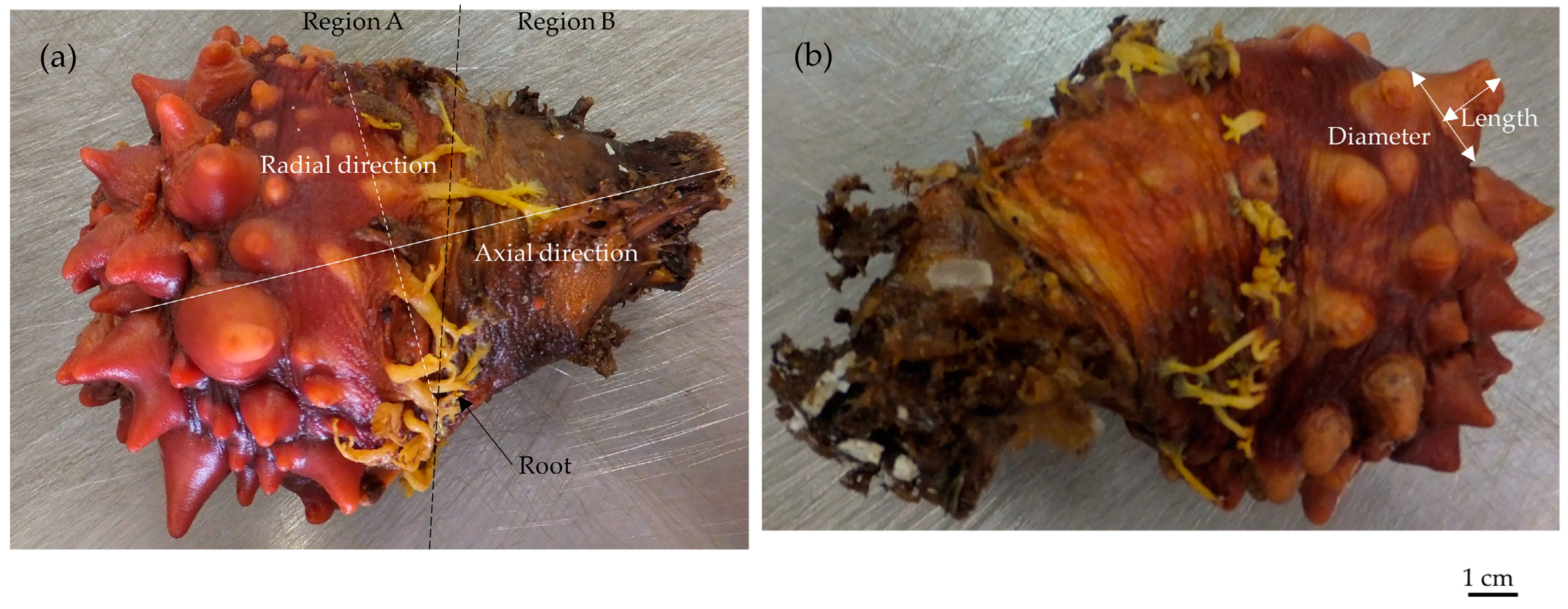
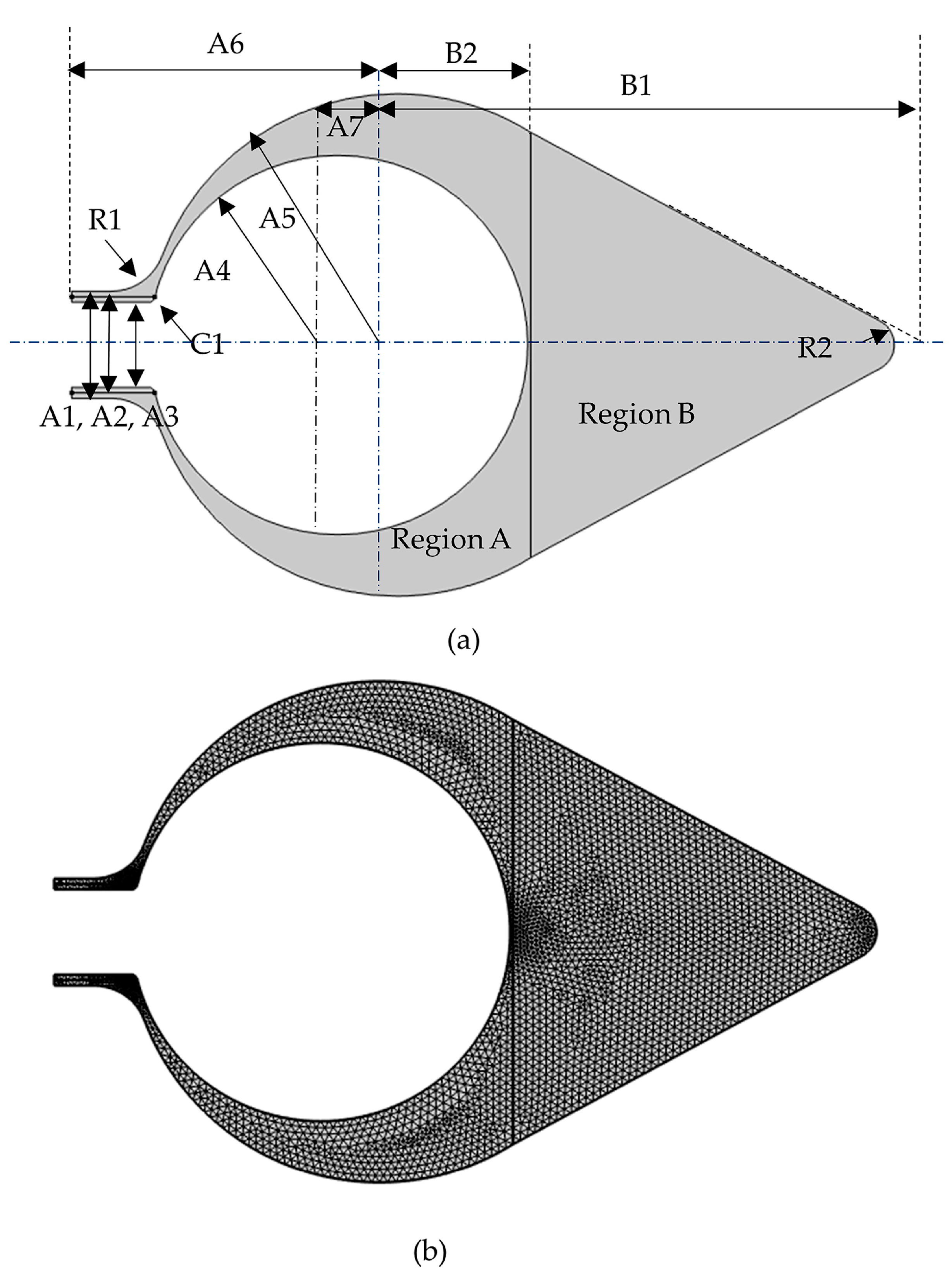
2.1. Size
2.2. Mechanical Properties and Load
2.3. Influence of Mechanical Parameters
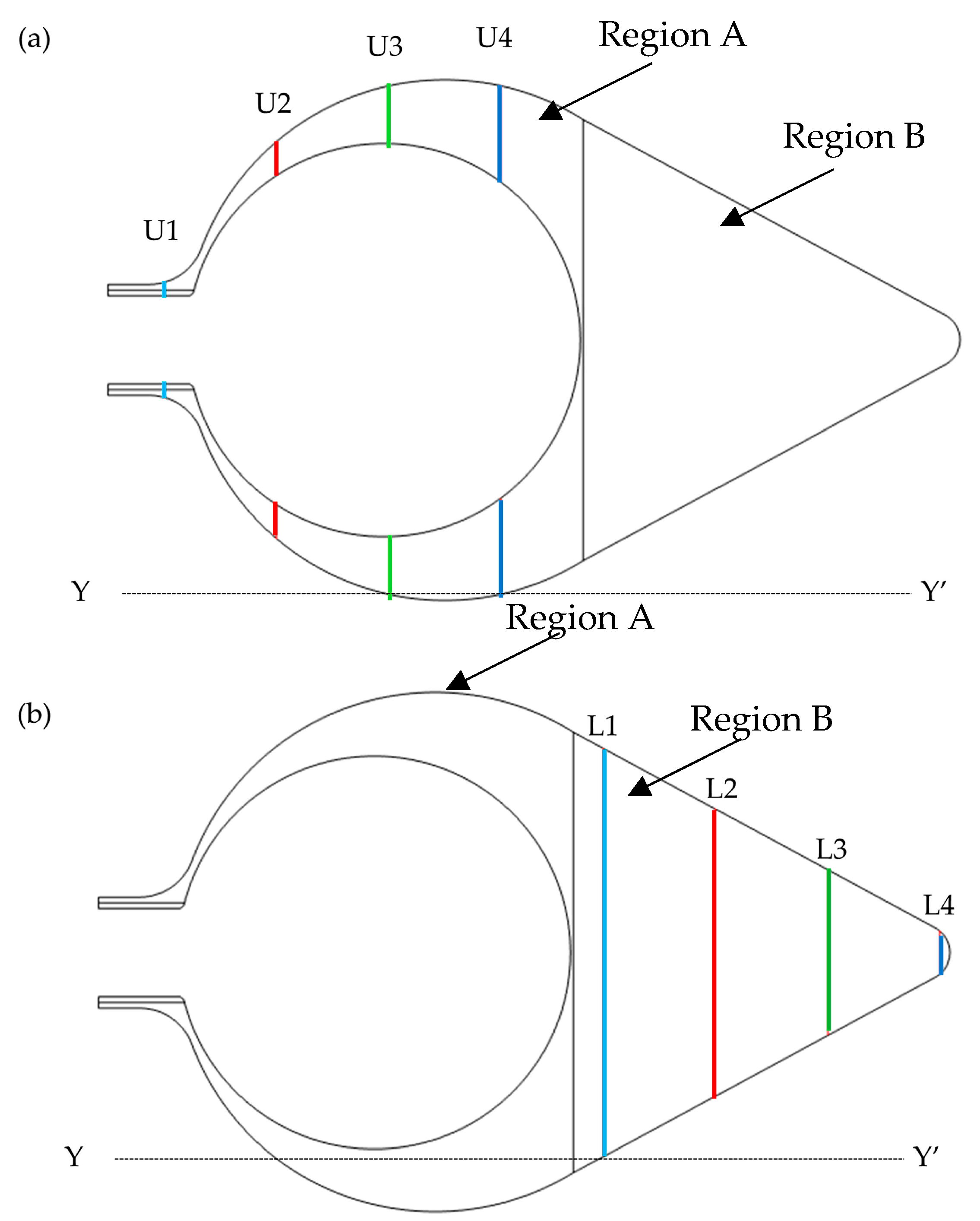
2.4. Parameters for the Mechanical Environment
3. Results
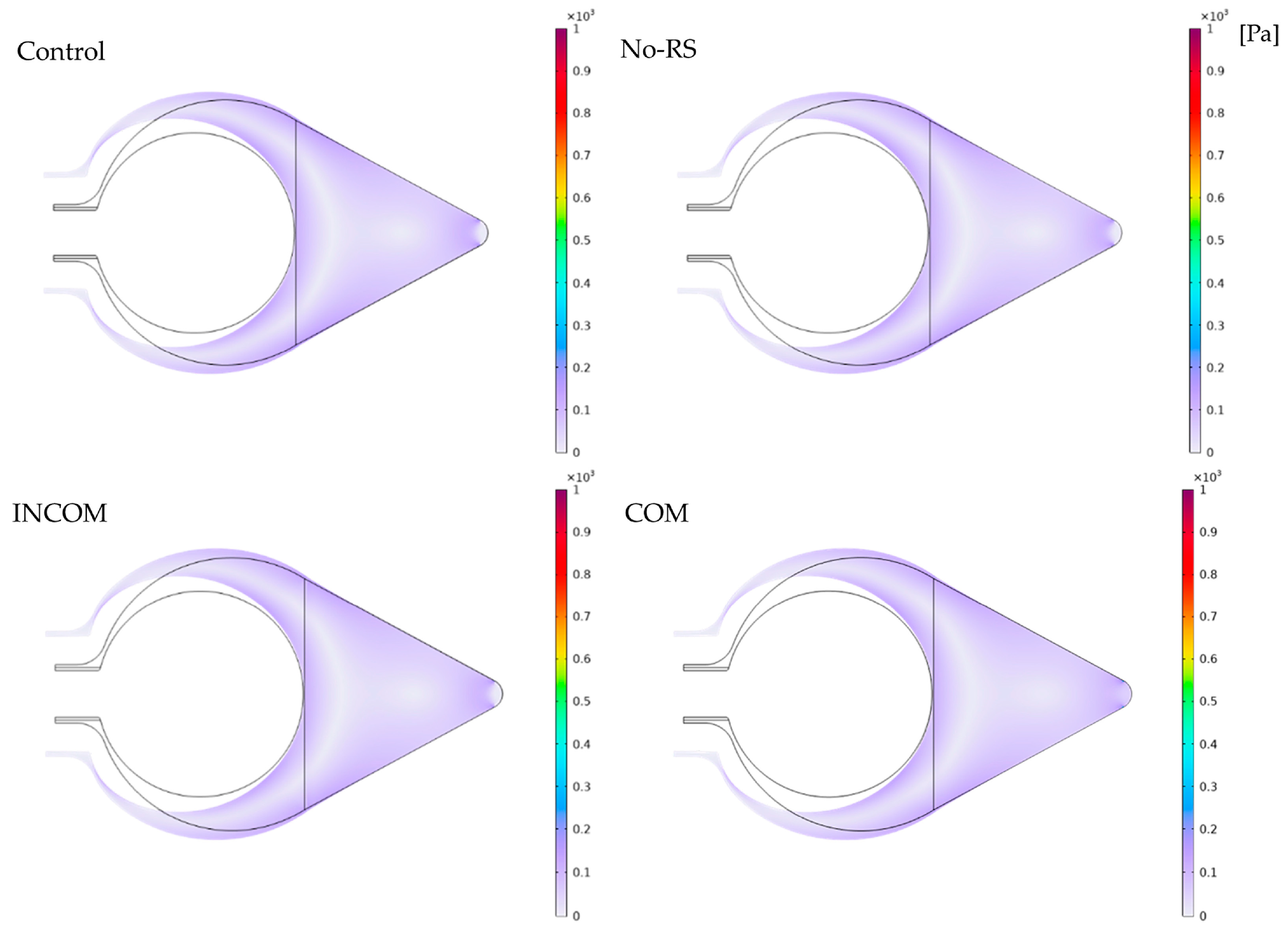
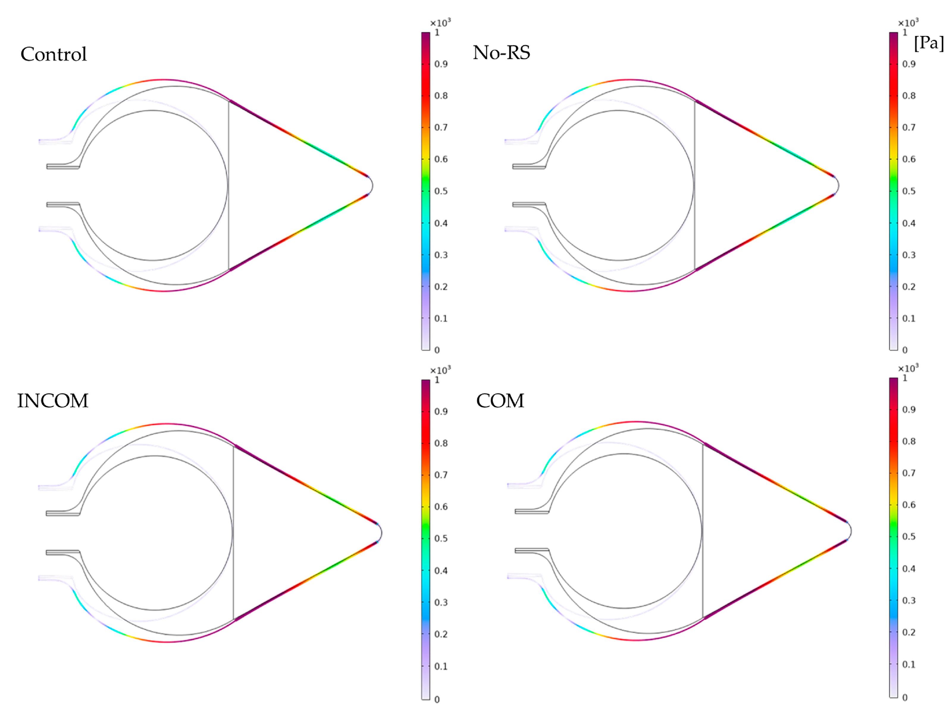
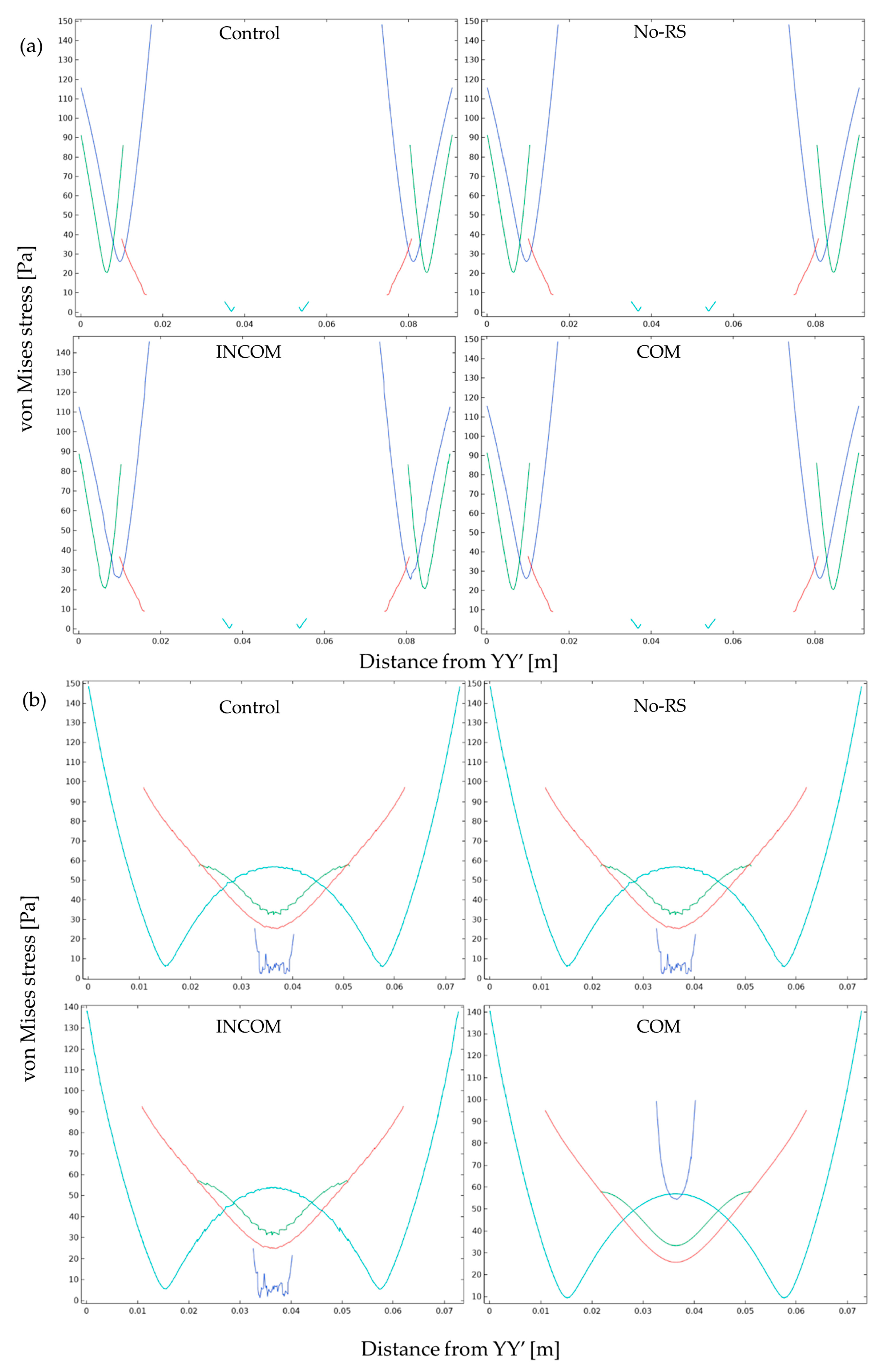
3.1. von Mises Stress
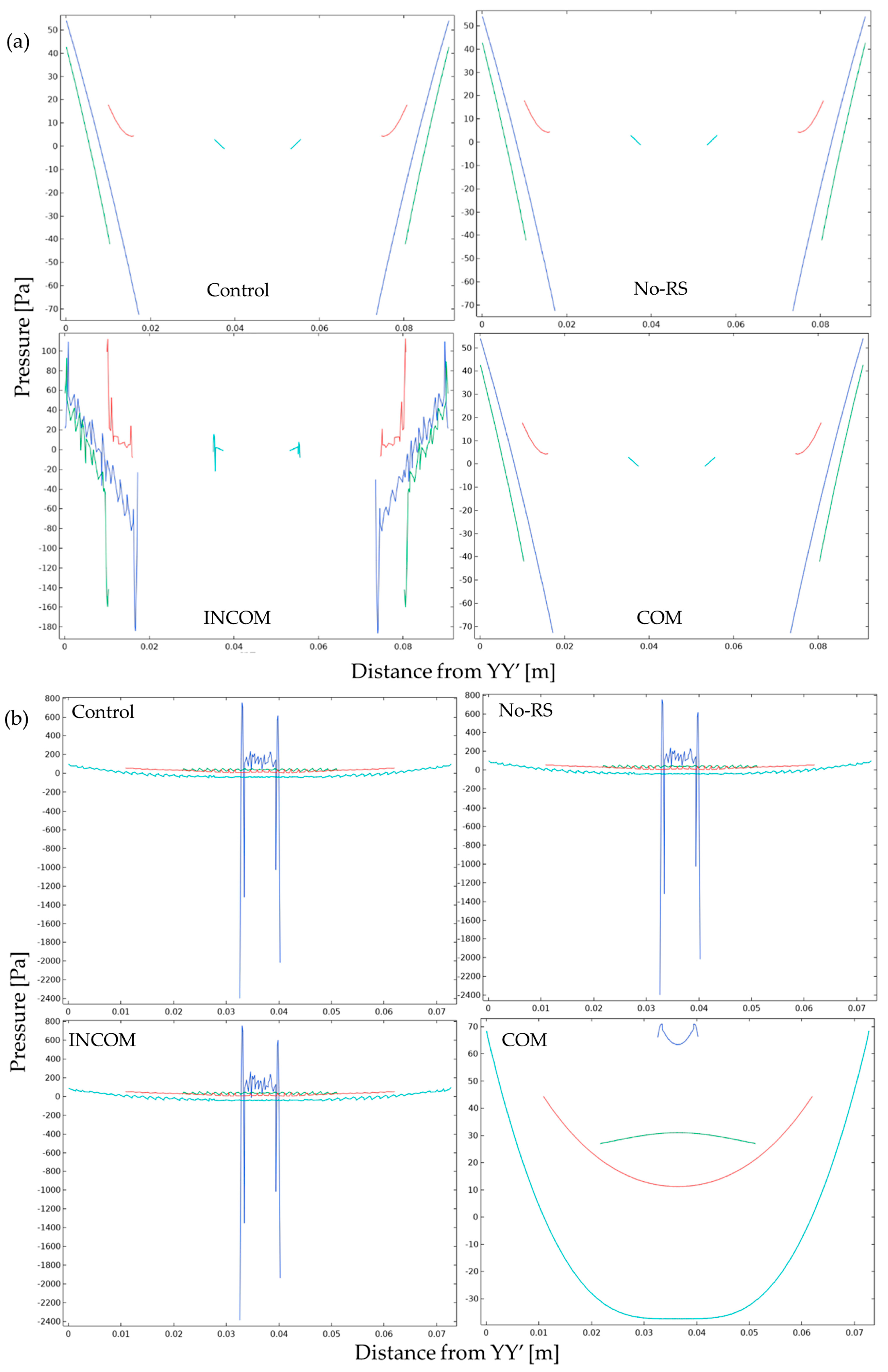
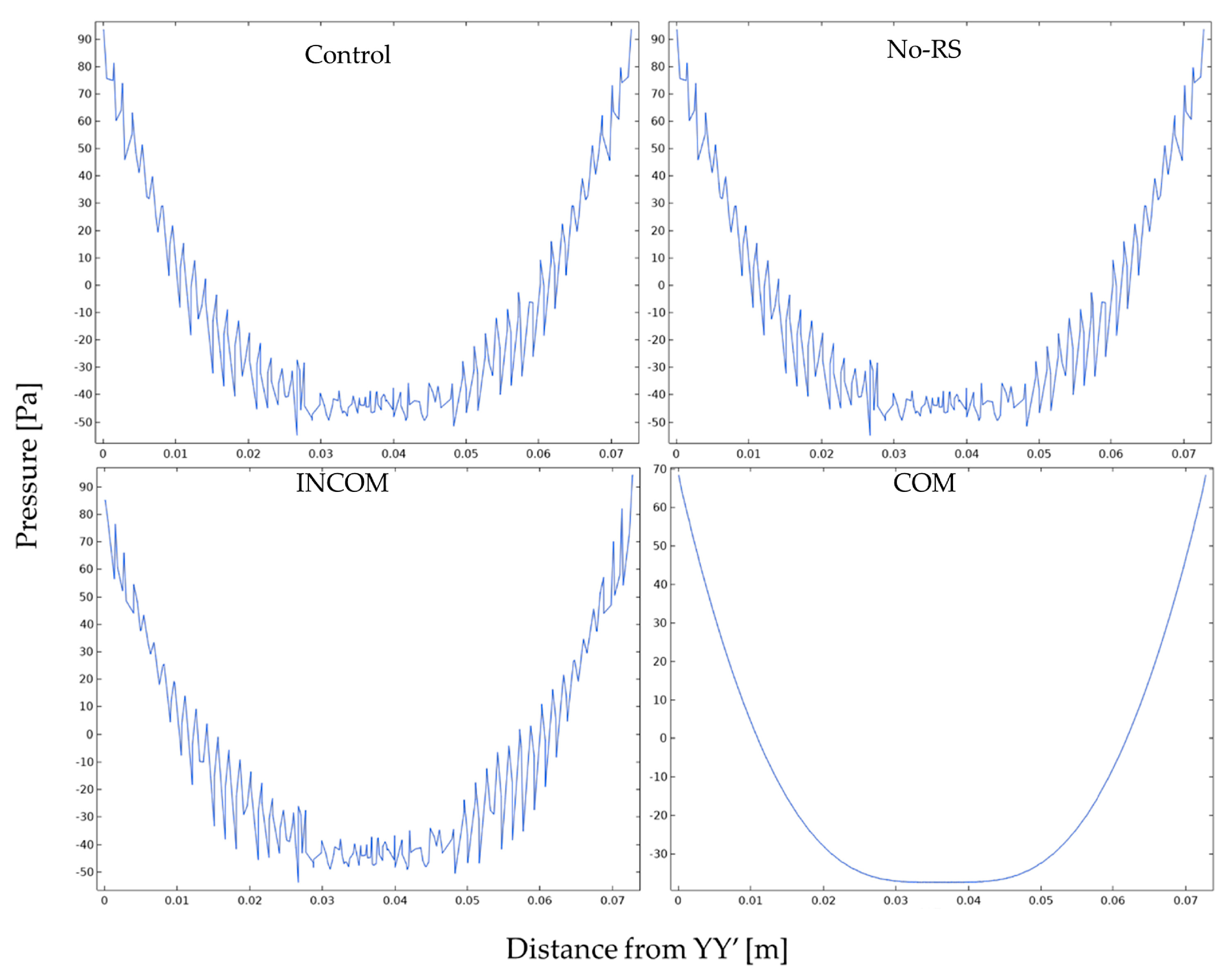
3.2. Pressure
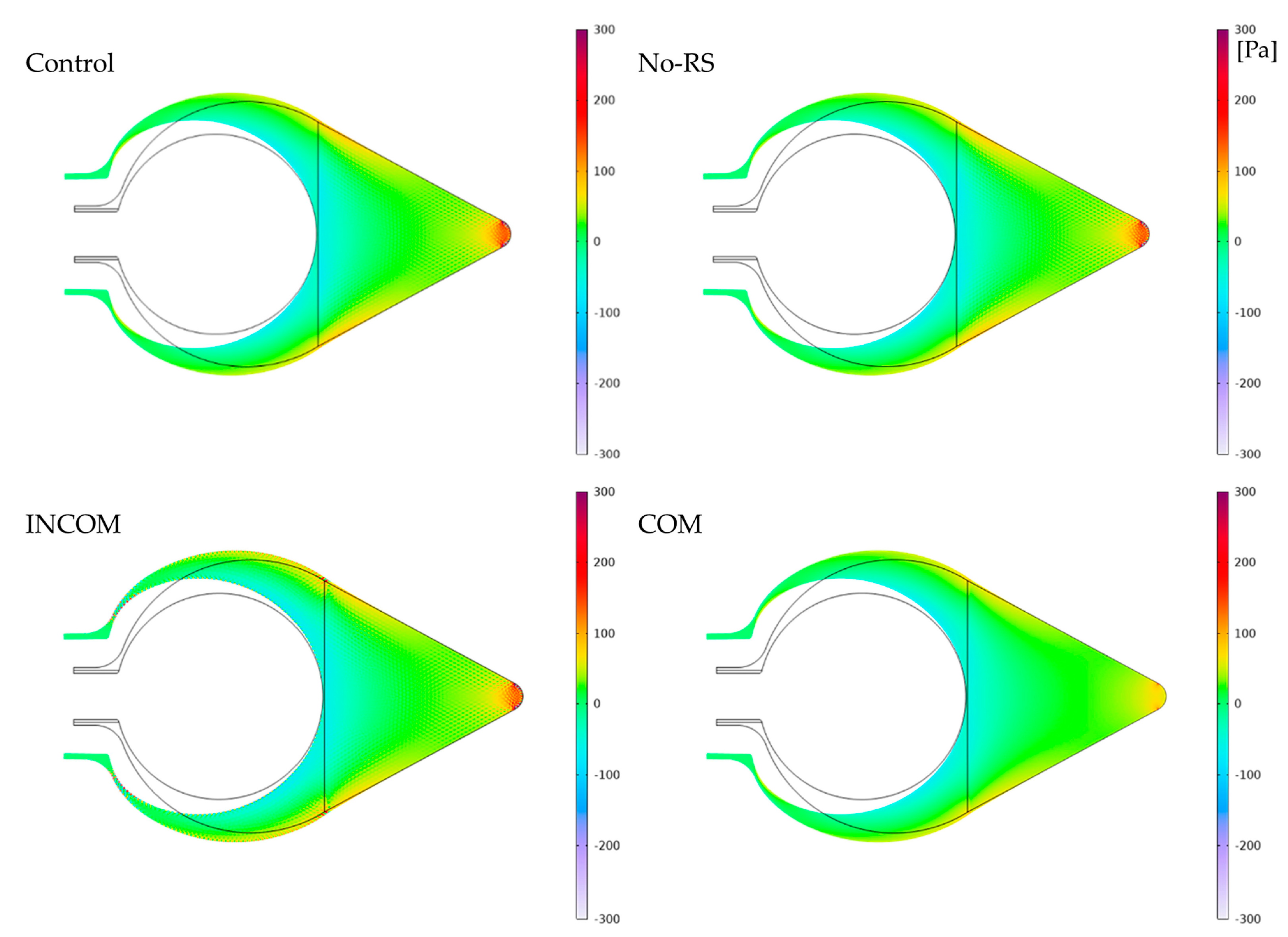
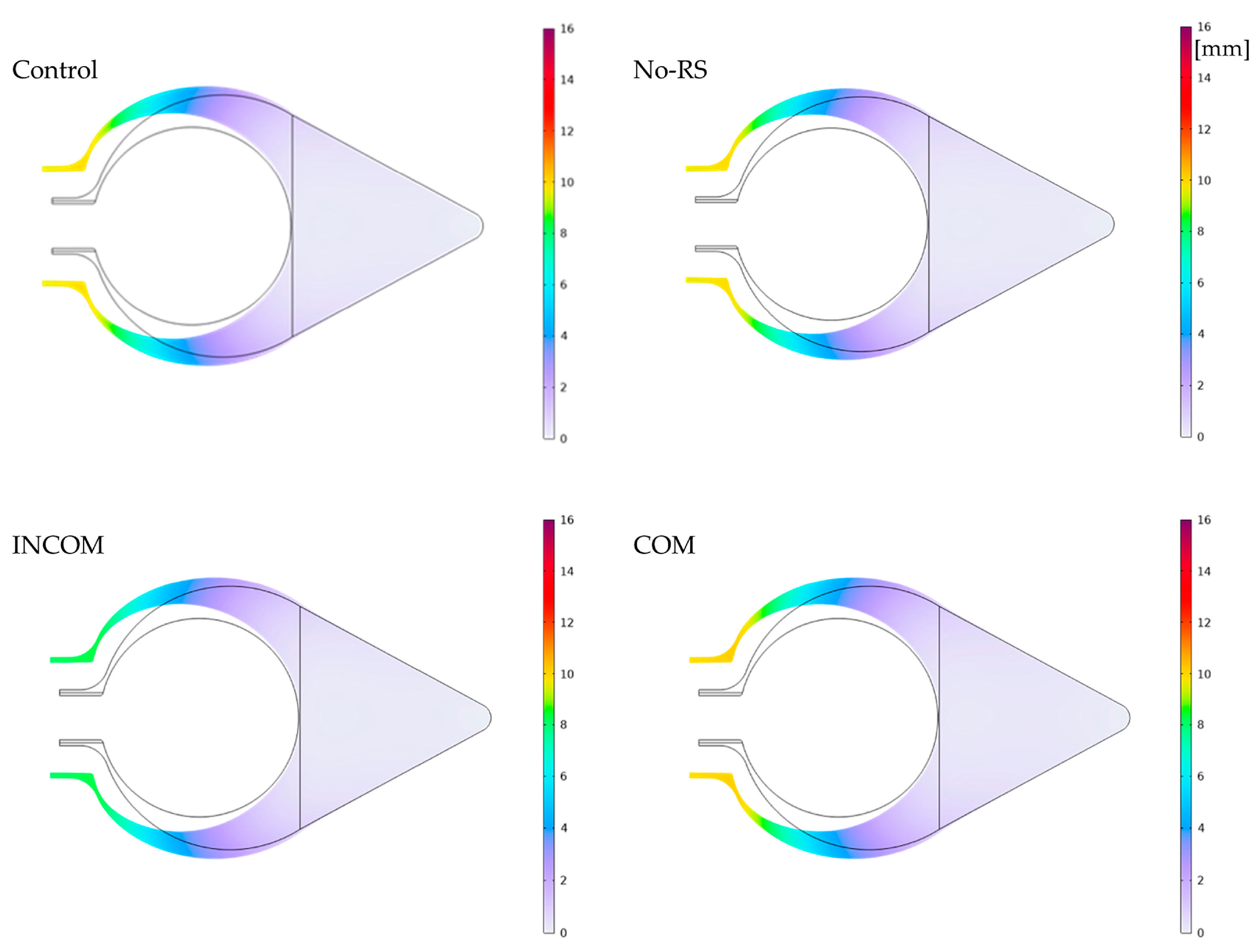
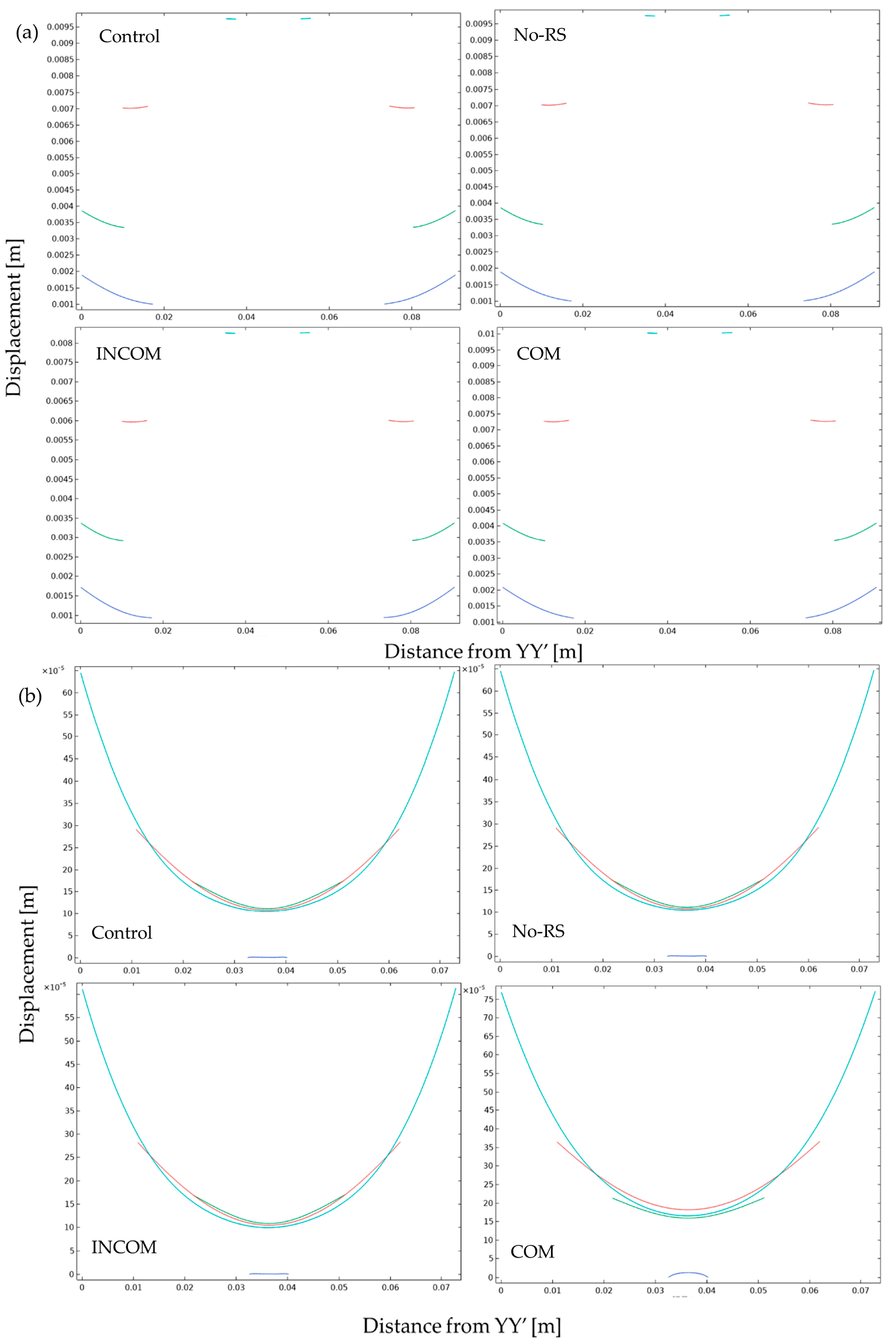
3.3. Displacement
4. Discussion
- The region close to the siphon deforms more than that close to the bottom. Hence, the elastic modulus at the region close to the siphon is smaller than that close to the bottom in this model.
- Deformation is accompanied by the influx and efflux of water. Hence, the region close to the siphon is compressible, while that close to the bottom is incompressible in this model.
- The tunic deforms on the inside after cutting so that there is residual stress. Hence, residual stress was set for this model.
- The outer region of the tunic could cause deformation. Hence, the main load was set to exert on the outer region in this model.
- The tunic could be categorized into three regions based on fiber distribution: the outer region is dense; the middle region is laminar; and the inner region is loose. Hence, the magnitude of the elastic modulus in each region is as follows: the outer region > the middle region > the inner region.
5. Conclusions
Funding
Institutional Review Board Statement
Data Availability Statement
Conflicts of Interest
References
- Berill, N.J. The Tunicate; Pisces Conservation Ltd.: Lymington, UK, 1950; ISBN 13978-1-904690-26-9. [Google Scholar]
- Goodbody, I. The physiology of ascidians. In Advances in Marine Biology; Russel, F.S., Yonge, M., Eds.; Elsevier Ltd.: Amsterdam, The Netherlands, 1974; Volume 12, pp. 1–149. [Google Scholar] [CrossRef]
- Belton, P.S.; Tanner, S.F.; Cartier, N.; Chanzy, H. High-resolution solid-state carbon-13 nuclear magnetic resonance spectroscopy of tunicin, an animal cellulose. Macromolecules 1989, 22, 1615–1617. [Google Scholar] [CrossRef]
- Larsson, P.T.; Westermark, U.; Iversen, T. Determination of the cellulose Iα allomorph content in a tunicate cellulose by CP/MAS 13C-NMR spectroscopy. Carbohydr. Res. 1995, 278, 339–343. [Google Scholar] [CrossRef]
- Zhao, Y.; Li, J. Excellent chemical and material cellulose from tunicates: Diversity in cellulose production yield and chemical and morphological structures from different tunicate species. Cellulose 2014, 21, 3427–3441. [Google Scholar] [CrossRef]
- Anno, K.; Otsuka, K.; Seno, N. A chitin sulfate-like polysaccharide from the test of the tunicate Halocynthia roretzi. Biochim. Biophys. Acta 1974, 362, 215–219. [Google Scholar] [CrossRef]
- Wagner, G.P. Evolution and multi-functionality of chitin system. EXS 1994, 69, 559–577. [Google Scholar] [CrossRef] [PubMed]
- Tuchiya, Y.; Suzuki, Y. Biochemical studies of the ascidian. Cynthia roretzi v. Drasche-VI. Nippon Suisan Gakkai 1962, 28, 222–226. [Google Scholar] [CrossRef]
- Kato, Y. Active movement of the tunic in Halocynthia roretzi. J. Biomech. Sci. Eng. 2010, 5, 163–174. [Google Scholar] [CrossRef]
- Kato, Y. Mechanical senses and the tunic structure in Halocynthia roretzi. In Proceedings of the Twenty-First International Offshore and Polar Engineering Conference, Maui, HI, USA, 19–24 June 2011; ISBN 978-1-880653-96-8. [Google Scholar]
- Kato, Y. The role of protein as a deformation controller in cellulose tissue. In Proceedings of the ASME 2012 International Mechanical Engineering Congress and Exposition. Volume 2: Biomedical and Biotechnology, Houston, TX, USA, 9–15 November 2012; pp. 607–613. [Google Scholar] [CrossRef]
- Das, S.M. On the structure and function of the ascidian test. J. Morphol. 1936, 59, 589–601. [Google Scholar] [CrossRef]
- Azumi, K.; Yokosawa, H.; Ishii, S. Lipopolysaccharide induces release of a metallo-protease from hemocytes of the ascidian, Halocynthia roretzi. Dev. Comp. Immunol. 1991, 15, 1–7. [Google Scholar] [CrossRef]
- Yokosawa, H.; Sawada, H.; Abe, Y.; Numakunai, T.; Ishii, S. Galactose-specific lectin in the hemolymph of solitary ascidian, Halocynthia roretzi: Isolation and characterization. Biochem. Biophys. Res. Commun. 1982, 107, 451–457. [Google Scholar] [CrossRef]
- Azumi, K.; Yokosawa, H.; Ishii, S. Halocyamines: Novel antimicrobial tetrapeptide-like substances isolated from the hemocytes of the solitary ascidian Halocynthia roretzi. Biochemistry 1990, 29, 159–165. [Google Scholar] [CrossRef]
- Yokosawa, H.; Harada, K.; Igarashi, K.; Abe, Y.; Takahashi, K.; Ishii, S. Galactose-specific lectin in the hemolymph of solitary ascidian, Halocynthia roretzi. Molecular, binding and functional properties. Biochim. Biohpys. Acta 1986, 870, 242–247. [Google Scholar] [CrossRef]
- Harada-Azumi, K.; Yokosawa, H.; Ishii, S. N-acetyl-galactosamine-specific lectin, a novel lectin in the hemolymph of the ascidian Halocynthia roretzi: Isolation, characterization and comparison with galactose-specific lectin. Comp. Biochem. Physiol. 1987, 88, 375–381. [Google Scholar] [CrossRef]
- Azumi, K.; Yoshimizu, M.; Suzuki, S.; Ezura, Y.; Yokosawa, H. Inhibitory effect of halocyamine, an antimicrobial substance from ascidian hemocytes, on the growth of fish viruses and marine bacteria. Experimentia 1990, 46, 1066–1068. [Google Scholar] [CrossRef] [PubMed]
- Azumi, K.; Ozeki, S.; Yokosawa, H.; Ishii, S. A novel lipopolysaccharide-binding hemagglutinin isolated from hemocytes of the solitary ascidian, Halocynthia roretzi: It can agglutinate bacteria. Dev. Comp. Immunol. 1991, 15, 9–16. [Google Scholar] [CrossRef] [PubMed]
- Azumi, K.; Satoh, N.; Yokosawa, H. Functional and structural characterization of hemocytes of the solitary ascidian, Halocynthia roretzi. J. Exp. Zool. 1993, 265, 309–316. [Google Scholar] [CrossRef]
- Kato, Y. Active characteristics in the tunic of Halocynthia roretzi—Tunic deformation and hemocytes. Chitin Chitosan Res. 2021, 27, 12–15. [Google Scholar]
- Kato, Y. Deformation control and mass transfer in the tunic of Halocynthia roretzi. Open Chem. J. 2018, 5, 1–17. [Google Scholar] [CrossRef]
- Kato, Y. Active Deformation in the tunic of Halocynthia roretzi: How the tissue composed of cellulose responds to stimuli and deforms. In Plant Stress Physiology; Hossain, A., Ed.; IntechOpen: London, UK, 2020; pp. 327–336. [Google Scholar] [CrossRef]
- Nishiyama, Y.; Langan, P.; Chanzy, H. Crystal structure and hydrogen-bonding system in cellulose Iβ from synchrotron X-ray and neutron fiber diffraction. J. Am. Chem. Soc. 2002, 124, 9074–9082. [Google Scholar] [CrossRef]
- Šturcová, A.; Davies, G.R.; Eichhorn, S.J. Elastic modulus and stress-transfer properties of tunicate cellulose whiskers. Biomacromolecules 2005, 6, 1055–1061. [Google Scholar] [CrossRef]
- Etale, A.; Onyianta, A.J.; Turner, S.R.; Eichhorn, S.J. Cellulose: A review of water interactions, applications in composites, and water treatment. Chem. Rev. 2023, 123, 2016–2048. [Google Scholar] [CrossRef]
- Wertz, J.-L.; Mercier, J.P.; Bédué, O. Cellulose Science and Technology; EPFL Press: Lausanne, Switzerland, 2010. [Google Scholar] [CrossRef]
- Bar-Cohen, Y. Electroactive Polymer (EAP) Actuators as Artificial Muscles: Reality, Potential, and Challenges, 2nd ed.; SPIE Press: Bellingham, WA, USA, 2004. [Google Scholar] [CrossRef]
- Kim, J.; Yun, S.; Ounaies, Z. Discovery of cellulose as a smart material. Macromolecules 2006, 39, 4202–4206. [Google Scholar] [CrossRef]
- Kim, J.; Seo, Y.B. Electro-active paper actuators. Smart Mater. Struct. 2002, 11, 355–360. [Google Scholar] [CrossRef]
- Li, Y.; Wang, J.; Huang, L.; Chen, L.; Gao, H.; Ni, Y.; Zheng, Q. High-sensitivity multiresponses cellulose-based actuators with configurable amplitude. ACS Sustain. Chem. Eng. 2022, 10, 6414–6425. [Google Scholar] [CrossRef]
- Chen, Q.; Sochor, B.; Chumakov, A.; Betker, M.; Ulrich, N.M.; Toimil-Molares, M.E.; Gordeyeva, K.; Söderberg, L.D.; Roth, S.V. Cellulose-reinforced programmable and stretch-healable actuators for smart packaging. Adv. Funct. Mater. 2022, 32, 2208074. [Google Scholar] [CrossRef]
- Chen, W.; Sun, B.; Biehl, P.; Zhang, K. Cellulose-based soft actuators. Macromol. Mater. Eng. 2022, 307, 2200072. [Google Scholar] [CrossRef]
- Qian, L.; Chen, C.; Huang, Y.; Ren, H.; Cao, X.; He, B.; Li, J. Nanocellulose-based electroactive actuators and their performance with various ions. Cellulose 2023, 30, 4455–4468. [Google Scholar] [CrossRef]
- Muzzarelli, R.; Jeuniaux, C.; Gooday, G.W. Chitin in Nature and Technology; Springer: New York, NY, USA, 1986. [Google Scholar] [CrossRef]
- Gopi, S.; Thomas, S.; Pius, A. Handbook of Chitin and Chitosan Volume 1: Preparation and Properties; Elsevier Inc: Amsterdam, The Netherlands, 2020. [Google Scholar] [CrossRef]
- Gopi, S.; Thomas, S.; Pius, A. Handbook of Chitin and Chitosan Volume 2: Composites and Nanocomposites from Chitin and Chitosan, Manufacturing and Characterisations; Elsevier Inc: Amsterdam, The Netherlands, 2020. [Google Scholar] [CrossRef]
- Gopi, S.; Thomas, S.; Pius, A. Handbook of Chitin and Chitosan Volume 3: Chitin and Chitosan Based Polymer Materials for Various Applications; Elsevier Inc: Amsterdam, The Netherlands, 2020. [Google Scholar] [CrossRef]
- Kurita, K. Chitin and chitosan: Functional biopolymers from marine crustaceans. Mar. Biotechnol. 2006, 8, 203–226. [Google Scholar] [CrossRef]
- Jayakumar, R.; Nwe, N.; Tokura, S.; Tamura, H. Review Sulfated chitin and chitosan as novel biomaterials. Int. J. Biol. Macromol. 2007, 40, 175–181. [Google Scholar] [CrossRef]
- Vigetti, D.; Theocharis, A.D. The Extracellular Matrix (Methods and Protocols); Springer Science+Business Media, LLC: New York, NY, USA, 2019. [Google Scholar] [CrossRef]
- Toda, N.; Horikawa, T.; Anno, K.; Seno, N. Galactan sulfate from the test of tunicates. Carbohydr. Res. 1978, 62, 389–392. [Google Scholar] [CrossRef]
- Albano, R.M.; Mourão, P.A.S. Presence of sulfated glycans in ascidian tunic and in the body wall of a cucumber. BBA—Gen. Subj. 1983, 760, 192–196. [Google Scholar] [CrossRef]
- Albano, R.M.; Mourão, P.A.S. Isolation, fractionation, and preliminary characterization of a novel class of sulfated glycans from the tunic of Styela plicata (Chordata Tunicata). J. Biol. Chem. 1986, 261, 758–765. [Google Scholar] [CrossRef] [PubMed]
- Mourão, P.A.S.; Perlin, A.S. Structural features of sulfated glycans from the tunic of Styela plicata (Chordata-Tunicata) A unique occurrence of L-galactose in sulfated polysaccharide. Eur. J. Biochem. 1987, 166, 431–436. [Google Scholar] [CrossRef] [PubMed]
- Pavão, M.S.G.; Albano, R.M.; Lawson, A.M.; Mourão, P.A.S. Structural heterogeneity among unique sulfated L-galactans from different species of ascidians (Tunicates). J. Biol. Chem. 1986, 264, 9972–9979. [Google Scholar] [CrossRef]
- Restrepo-Espinosa, D.C.; Román, Y.; Colorado-Ríos, J.; Paixão de Santana-Filho, A.; Sasaki, G.L.; Cipriani, T.R.; Martínez, A.; Iacomini, M.; Pavão, M.S.G. Structural analysis of a sulfated galactan from the tunic of the ascidian Microcosmus exasperatus and its inhibitory effect of the intrinsic coagulation pathway. Int. J. Biol. Macromol. 2017, 105, 1391–1400. [Google Scholar] [CrossRef]
- Pavão, M.S.G.; Mourão, P.A.S.; Mulloy, B.; Tollefsen, D.M. A unique dermatan sulfate-like glycosaminoglycan from Ascidian. Its structure and the effect of its unusual sulfation pattern on anticoagulant activity. J. Biol. Chem. 1995, 270, 31027–31036. [Google Scholar] [CrossRef]
- Pavão, M.S.G.; Aiello, K.R.M.; Werneck, C.C.; Silva, L.C.F.; Valente, A.-P.; Mulloy, B.; Colwell, N.S.; Tollefsen, D.M.; Mourão, P.A.S. Highly sulfated dermatan sulfates from ascidians. Structure versus anticoagulant activity of these glycosaminoglycans. J. Biol. Chem. 1998, 273, 27848–27857. [Google Scholar] [CrossRef]
- Santos, J.A.; Mulloy, B.; Mourão, P.A.S. Structural diversity among sulfated α-L-galactans from ascidians (tunicates). Studies on the species Ciona intestinalis and Herdmania monus. Eur. J. Biochem. 1992, 204, 669–677. [Google Scholar] [CrossRef]
- Bedhi, E.; Laezza, A.; Parilli, M.; Iadonisi, A. A review of chemical methods for the selective sulfation and desulfation of polysaccharides. Carbohydr. Polym. 2017, 174, 1224–1239. [Google Scholar] [CrossRef]
- Okay, O. General properties of hydrogels. In Hydrogel Sensors and Actuators; Gerlach, G., Armdt, K.-F., Eds.; Springer: Berlin/Heidelberg, Germany, 2009; pp. 1–14. [Google Scholar] [CrossRef]
- Navarra, M.A.; Boscom, C.D.; Moreno, J.S.; Vitucci, F.M.; Paolone, A.; Panero, S. Synthesis and characterization of cellulose-based hydrogels to be used as gel electrolytes. Membranes 2015, 5, 810–823. [Google Scholar] [CrossRef]
- Sun, Z.; Yang, L.; Zhao, J.; Song, W. Natural cellulose-full-hydrogels bioinspired electroactive artificial muscles: Highly conductive ionic transportation channels and ultrafast electromechanical response. J. Electrochem. Soc. 2020, 167, 47515. [Google Scholar] [CrossRef]
- Migliorini, L.; Yan, Y.; Pezzotta, F.; Veronesi, F.M.S.; Lenardi, C.; Rondinini, S.; Santaniello, T.; Milani, P. Cellulose-based electroactive hydrogels for seaweed mimicking toward hybrid habitats creation. MRS Commun. 2018, 8, 1129–1134. [Google Scholar] [CrossRef]
- Zhang, J.; Said, F.M.; Jing, Z. Hydrogels based on seafood chitin: From extraction to the development. Int. J. Biol. Macromol. 2023, 253, 126482. [Google Scholar] [CrossRef]
- Liao, J.; Hou, B.; Huang, H. Preparation, properties and drug controlled release of chitin-based hydrogels: An updated review. Carbohydr. Polym. 2022, 283, 119177. [Google Scholar] [CrossRef] [PubMed]
- Liu, R.-R.; Shin, Q.-Q.; Meng, Y.-F.; Zhou, Y.; Mao, L.-B.; Yu, S.-H. Biomimetic chitin hydrogel via chemical transformation. Nano Res. 2023. [Google Scholar] [CrossRef]
- Liao, J.; Huang, H. Construction of hydrogels based on the chitin from Hericium erinaceus residue: Role of molecular weight. Cellulose 2022, 29, 2211–2222. [Google Scholar] [CrossRef]
- Shen, X.; Shamshina, J.L.; Berton, P.; Gurau, G.; Rogers, R.D. Hydrogels based on cellulose and chitin: Fabrication, properties, and applications. Green Chem. 2016, 18, 53. [Google Scholar] [CrossRef]
- Kasprzak, D.; Galiński, M. Chitin and chitin-cellulose composite hydrogels prepared by ionic liquid-based process as the novel electrolytes for electrochemical capacitors. J. Solid State Electrochem. 2021, 25, 2549–2563. [Google Scholar] [CrossRef]
- Crans, D.C.; Smee, J.J.; Gaidamasukas, E.; Yang, L. The chemistry and biochemistry of vanadium and the biological activities exerted by vanadium compounds. Chem. Rev. 2004, 104, 849–902. [Google Scholar] [CrossRef]
- Pessoa, J.C.; Garribba, E.; Santos, M.F.A.; Santos-Silva, T. Vanadium and proteins: Uptake, transport, structure, activity and function. Coordinat. Chem. Rev. 2015, 301–302, 49–86. [Google Scholar] [CrossRef]
- Ueki, T.; Yamaguchi, N.; Romaidi; Isago, Y.; Tanahashi, H. Vanadium accumulation in ascidians; A system overview. Coordinat. Chem. Rev. 2015, 301, 300–308. [Google Scholar] [CrossRef]
- Gunasinghe, M.A.; Kim, S.M. Antioxidant and antidiabetic activities of vanadium binding proteins purified from the seq squirt Halocynthia roretzi. J. Food. Sci. Technol. 2018, 55, 1840–1849. [Google Scholar] [CrossRef] [PubMed]
- Kim, A.T.; Kim, D.O. Anti-inflammatory effects of vanadium-binding protein from Halocynthia roretzi in LPS-stimulated RAW 264.7 macrophages through NF-κB and MAPK pathway. Int. J. Biol. Macromol. 2019, 133, 732–738. [Google Scholar] [CrossRef] [PubMed]
- Greaves, G.N.; Greer, A.L.; Lakes, R.S.; Rouxel, T. Poisson’s ratio and modern materials. Nat. Mater. 2011, 10, 823–837. [Google Scholar] [CrossRef] [PubMed]


| Parameter * | Size [mm] ** |
|---|---|
| A1 | 19.75 |
| A2 | 17.75 |
| A3 | 15.75 |
| A4 | 35 |
| A5 | 46.36 |
| A6 | 60.04 |
| A7 | 10.85 |
| B1 | 97.29 |
| B2 | 24.66 |
| R1 *** | 0.5 |
| R2 *** | 1 |
| C1 **** | 0.5 |
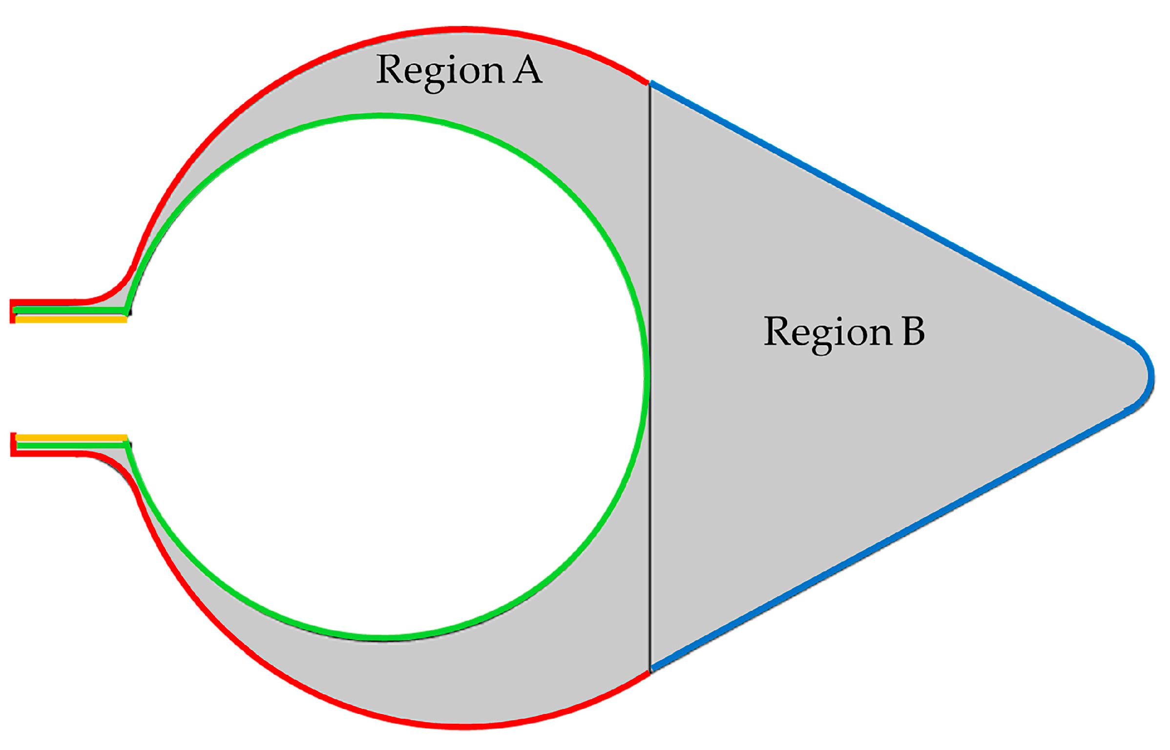
| Component | Elastic Modulus [Pa] | Poisson’s Ratio | Thickness [mm] | Residual Stress [Pa] | |
|---|---|---|---|---|---|
| Magnitude | Type | ||||
| Region A | 5 × 10³ | 0.3 | - | - | |
| Region B | 1 × 10⁴ | 0.4999 | - | - | |
| LA-1 | 5 × 10⁴ | 0.3 | 0.1 | 0.01 | Compressive |
| LA-2 | 1 × 10³ | 0.3 | 0.1 | 0.01 | Tensile |
| LA-3 | 1 × 10³ | 0.3 | 0.1 | 0.01 | Compressive |
| LB | 1 × 10⁵ | 0.3 | 0.2 | 0.1 | Compressive |
| Component | Load [N/m] | ||
|---|---|---|---|
| Category | Type | Magnitude | Type |
| LA-1 | Outer region (Main (except siphon)) | 5 | Compressive |
| LA-3 | Outer region (siphon) | 0.5 | Compressive |
| LB | Outer region (bottom) | 10 | Compressive |
| LA-2 | Inner region | 0.01 | Tensile |
Disclaimer/Publisher’s Note: The statements, opinions and data contained in all publications are solely those of the individual author(s) and contributor(s) and not of MDPI and/or the editor(s). MDPI and/or the editor(s) disclaim responsibility for any injury to people or property resulting from any ideas, methods, instructions or products referred to in the content. |
© 2023 by the author. Licensee MDPI, Basel, Switzerland. This article is an open access article distributed under the terms and conditions of the Creative Commons Attribution (CC BY) license (https://creativecommons.org/licenses/by/4.0/).
Share and Cite
Kato, Y. Active Contraction in the Stable Mechanical Environment of the Tunic of the Ascidian, Halocynthia roretzi, a Polysaccharide-Based Tissue with Blood Circulatory System. Polymers 2023, 15, 4329. https://doi.org/10.3390/polym15214329
Kato Y. Active Contraction in the Stable Mechanical Environment of the Tunic of the Ascidian, Halocynthia roretzi, a Polysaccharide-Based Tissue with Blood Circulatory System. Polymers. 2023; 15(21):4329. https://doi.org/10.3390/polym15214329
Chicago/Turabian StyleKato, Yoko. 2023. "Active Contraction in the Stable Mechanical Environment of the Tunic of the Ascidian, Halocynthia roretzi, a Polysaccharide-Based Tissue with Blood Circulatory System" Polymers 15, no. 21: 4329. https://doi.org/10.3390/polym15214329