
Piezo-Enhanced Photocatalytic Activity of the Electrospun Fibrous Magnetic PVDF/BiFeO3 Membrane

 , , , , ,
Abstract
:
1. Introduction
2. Materials and Methods
2.1. Characterization
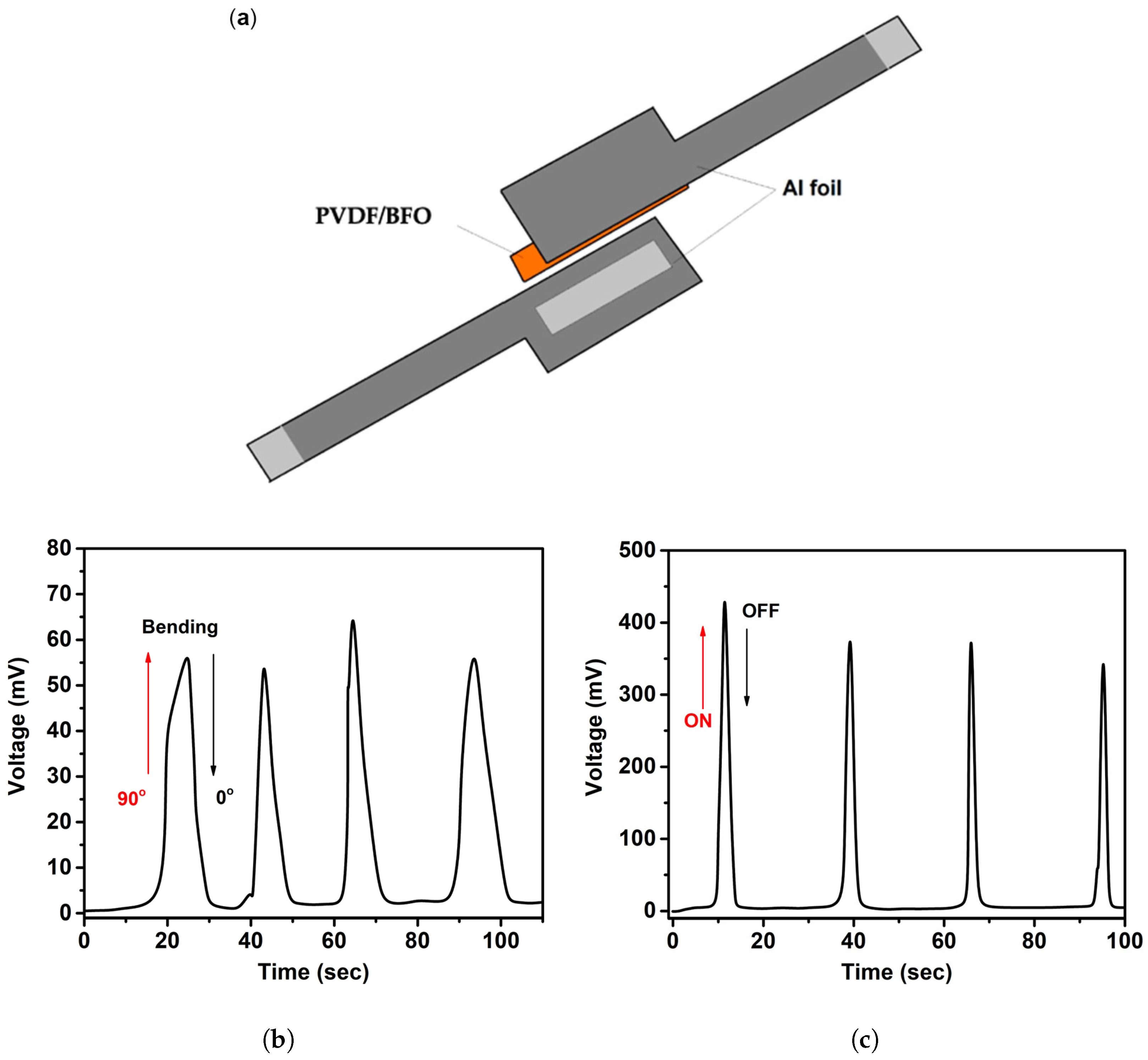
- The PENG was fixed on a flat surface and manually bent and unbent by 90°.
- The PENG was immersed in an ultrasonic bath, fixed stationary, and the ultrasound was turned on and off.
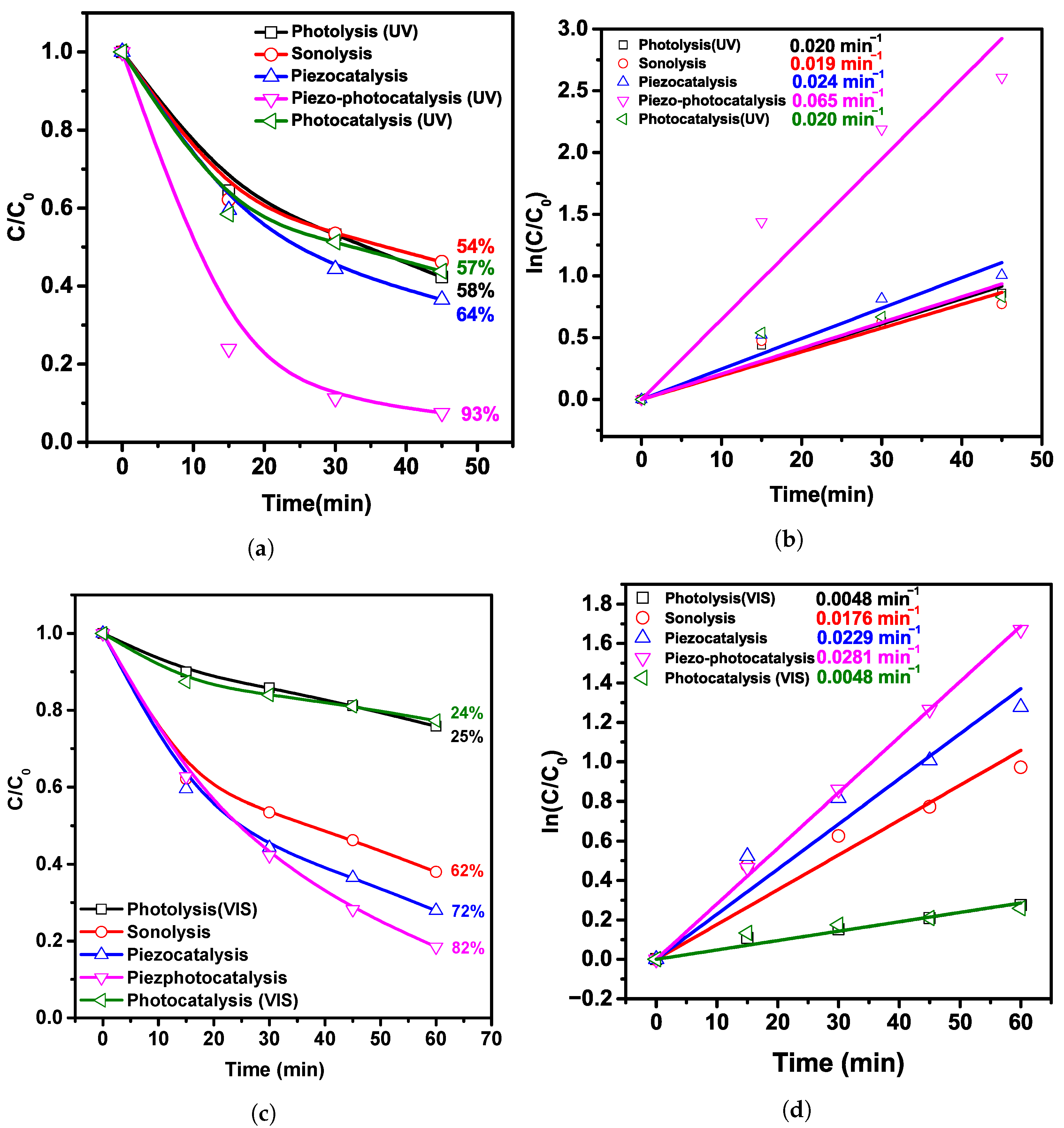
2.2. Piezo-Photocatalytic Experiment
3. Results
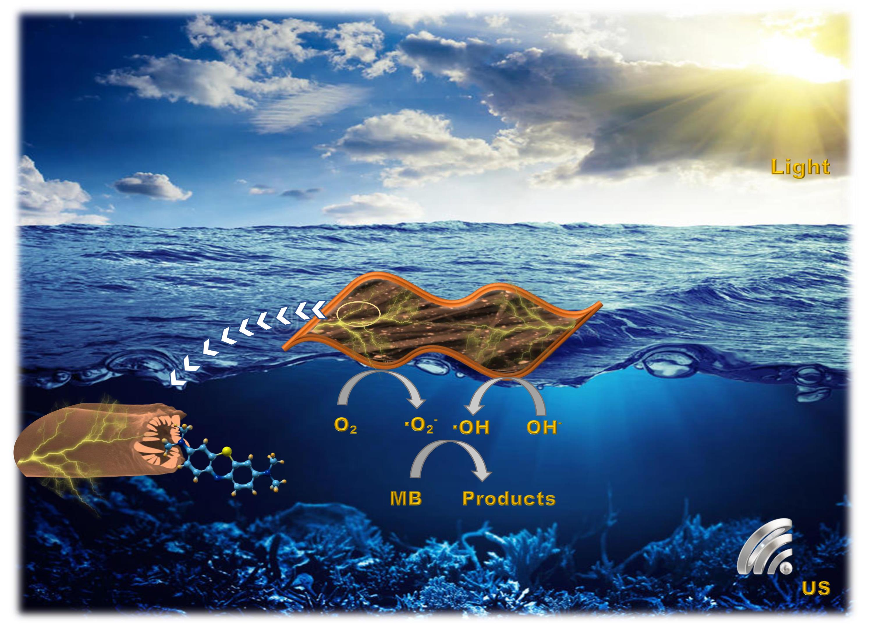
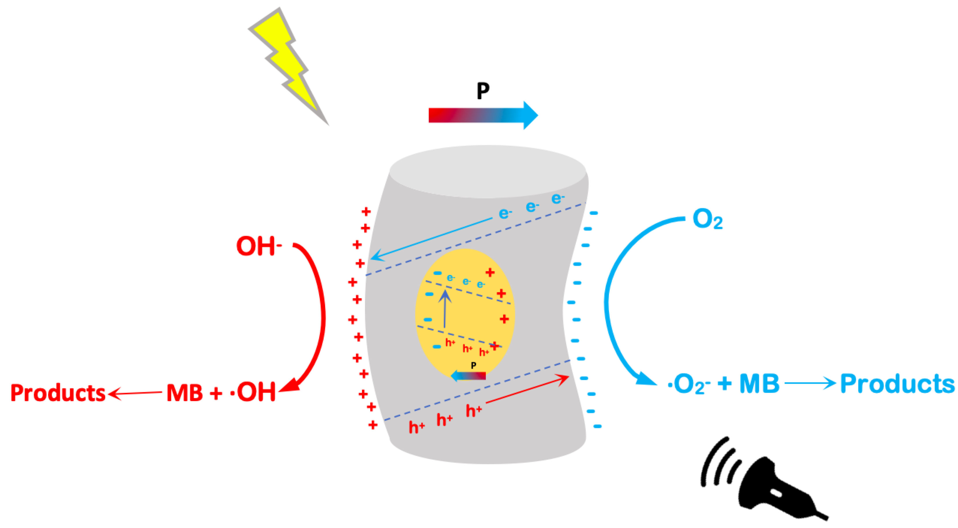
- Forming a potential difference while being impacted by acoustic energy.
- A piezoelectric catalyst forms electron–hole pairs under the influence of shock waves produced by the burst of cavitation microbubbles.
4. Conclusions
Author Contributions
Funding
Institutional Review Board Statement
Data Availability Statement
Acknowledgments
Conflicts of Interest
Sample Availability
Abbreviations
| AOP | advanced oxidation process |
| BFO | bismuth ferrite |
| CCD | charge-coupled device |
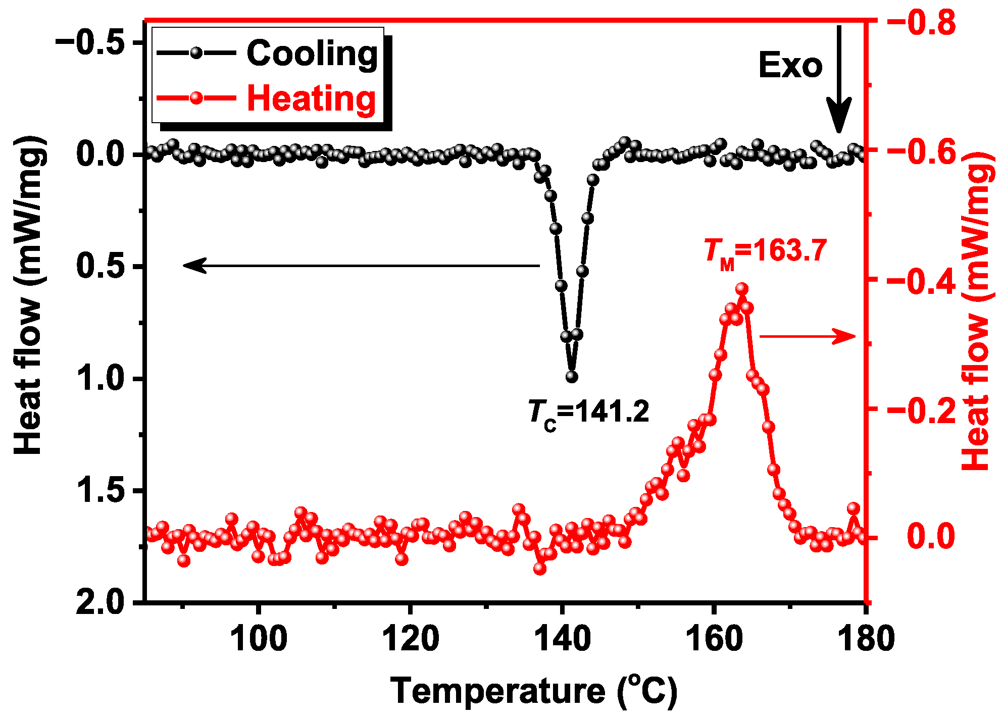
| DSC | differential scanning calorimetry |
| EDS | energy-dispersive spectroscopy |
| FEA | fraction of the electroactive (phase) |
| FTIR | Fourier-transform infrared spectroscopy |
| MB | methylene blue |
| PENG | piezoelectric nanogenerator |
| PP | polypropylene |
| PVDF | polyvinylidene fluoride |
| RhB | Rhodamine B |
| SEM | scanning electron microscope |
| TGA | thermogravimetric analysis |
| US | ultrasonic |
| UV | ultraviolet |
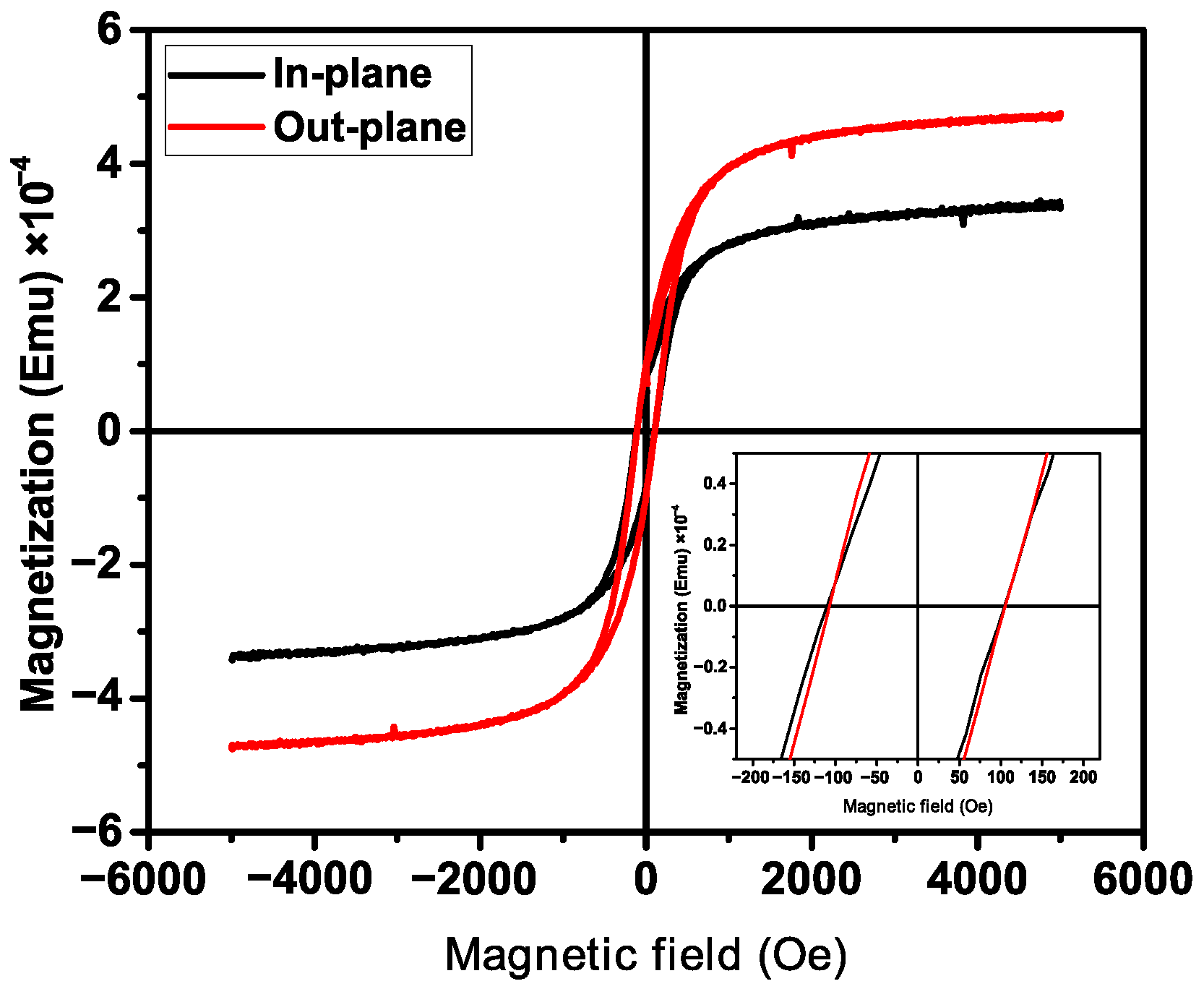
| VSM | vibrating-sample magnetometer |
| XPS | X-ray photoelectron spectroscopy |
References
- Vaiano, V.; Sacco, O.; Sannino, D.; Ciambelli, P. Nanostructured N-doped TiO2 coated on glass spheres for the photocatalytic removal of organic dyes under UV or visible light irradiation. Appl. Catal. B Environ. 2015, 170–171, 153–161. [Google Scholar] [CrossRef]
- Singha, K.; Pandit, P.; Maity, S.; Sharma, S.R. Harmful environmental effects for textile chemical dyeing practice. In Green Chemistry for Sustainable Textiles: Modern Design and Approaches; Elsevier: Amsterdam, The Netherlands, 2021; pp. 153–164. [Google Scholar] [CrossRef]
- Al-Tohamy, R.; Ali, S.S.; Li, F.; Okasha, K.M.; Mahmoud, Y.A.; Elsamahy, T.; Jiao, H.; Fu, Y.; Sun, J. A critical review on the treatment of dye-containing wastewater: Ecotoxicological and health concerns of textile dyes and possible remediation approaches for environmental safety. Ecotoxicol. Environ. Saf. 2022, 231, 113160. [Google Scholar] [CrossRef] [PubMed]
- Kishor, R.; Purchase, D.; Saratale, G.D.; Saratale, R.G.; Ferreira, L.F.R.; Bilal, M.; Chandra, R.; Bharagava, R.N. Ecotoxicological and health concerns of persistent coloring pollutants of textile industry wastewater and treatment approaches for environmental safety. J. Environ. Chem. Eng. 2021, 9, 105012. [Google Scholar] [CrossRef]
- Miklos, D.B.; Remy, C.; Jekel, M.; Linden, K.G.; Drewes, J.E.; Hübner, U. Evaluation of advanced oxidation processes for water and wastewater treatment—A critical review. Water Res. 2018, 139, 118–131. [Google Scholar] [CrossRef] [PubMed]
- Tikhanova, S.M.; Lebedev, L.A.; Martinson, K.D.; Chebanenko, M.I.; Buryanenko, I.V.; Semenov, V.G.; Nevedomskiy, V.N.; Popkov, V.I. The synthesis of novel heterojunction h-YbFeO3/o-YbFeO3 photocatalyst with enhanced Fenton-like activity under visible-light. New J. Chem. 2021, 45, 1541–1550. [Google Scholar] [CrossRef]
- Tikhanova, S.M.; Lebedev, L.A.; Kirillova, S.A.; Tomkovich, M.V.; Popkov, V.I. Synthesis, structure, and visible-light-driven activity of o-YbFeO3/h-YbFeO3/CeO2 photocatalysts. Chim. Technol. Acta 2021, 8, 20218407. [Google Scholar] [CrossRef]
- Ismail, G.A.; Sakai, H. Review on effect of different type of dyes on advanced oxidation processes (AOPs) for textile color removal. Chemosphere 2022, 291, 132906. [Google Scholar] [CrossRef]
- Rabadanova, A.E.; Gadzhimagomedov, S.K.; Alikhanov, N.M.; Ilyichev, M.V.; Emirov, R.M.; Orudzhev, F.F.; Faradzhev, S.P.; Saipulaev, P.M. Structure and dielectric properties of Bi1−xLaxFeO3 nanostructured ceramics. Ferroelectrics 2021, 576, 1–7. [Google Scholar] [CrossRef]
- Orudzhev, F.; Ramazanov, S.; Sobola, D.; Alikhanov, N.; Holcman, V.; Škvarenina, L.; Kaspar, P.; Gadjilov, G. Piezoelectric Current Generator Based on Bismuth Ferrite Nanoparticles. Sensors 2020, 20, 6736. [Google Scholar] [CrossRef]
- Amirov, A.A.; Makoed, I.I.; Chaudhari, Y.A.; Bendre, S.T.; Yusupov, D.M.; Asvarov, A.S.; Liedienov, N.A.; Pashchenko, A.V. Magnetocaloric Effect in BiFe1−xZnxO3 Multiferroics. J. Supercond. Nov. Magn. 2018, 31, 3283–3288. [Google Scholar] [CrossRef]
- Alikhanov, N.M.; Rabadanov, M.K.; Orudzhev, F.F.; Gadzhimagomedov, S.K.; Emirov, R.M.; Sadykov, S.A.; Kallaev, S.N.; Ramazanov, S.M.; Abdulvakhidov, K.G.; Sobola, D. Size-dependent structural parameters, optical, and magnetic properties of facile synthesized pure-phase BiFeO3. J. Mater. Sci. Mater. Electron. 2021, 32, 13323–13335. [Google Scholar] [CrossRef]
- Orudzhev, F.; Alikhanov, N.r.; Rabadanov, M.; Ramazanov, S.; Isaev, A.; Gadzhimagomedov, S.; Aliyev, A.; Abdullaev, V. Synthesis and study of the properties of magnetically separable nanophotocatalyst BiFeO3. Chem. Probl. 2018, 16, 484–495. [Google Scholar] [CrossRef]
- Orudzhev, F.F.; Alikhanov, N.M.; Ramazanov, S.M.; Sobola, D.S.; Murtazali, R.K.; Ismailov, E.H.; Gasimov, R.D.; Aliev, A.S.; Ţălu, Ş. Morphotropic Phase Boundary Enhanced Photocatalysis in Sm Doped BiFeO3. Molecules 2022, 27, 7029. [Google Scholar] [CrossRef] [PubMed]
- Mushtaq, F.; Chen, X.; Hoop, M.; Torlakcik, H.; Pellicer, E.; Sort, J.; Gattinoni, C.; Nelson, B.J.; Pané, S. Piezoelectrically Enhanced Photocatalysis with BiFeO3 Nanostructures for Efficient Water Remediation. iScience 2018, 4, 236–246. [Google Scholar] [CrossRef]
- Ponraj, C.; Vinitha, G.; Daniel, J. A review on the visible light active BiFeO3 nanostructures as suitable photocatalyst in the degradation of different textile dyes. Environ. Nanotechnol. Monit. Manag. 2017, 7, 110–120. [Google Scholar] [CrossRef]
- Lam, S.M.; Sin, J.C.; Mohamed, A.R. A newly emerging visible light-responsive BiFeO3 perovskite for photocatalytic applications: A mini review. Mater. Res. Bull. 2017, 90, 15–30. [Google Scholar] [CrossRef]
- You, D.; Liu, L.; Yang, Z.; Xing, X.; Li, K.; Mai, W.; Guo, T.; Xiao, G.; Xu, C. Polarization-induced internal electric field to manipulate piezo-photocatalytic and ferro-photoelectrochemical performance in bismuth ferrite nanofibers. Nano Energy 2022, 93, 106852. [Google Scholar] [CrossRef]
- Nguyen, T.N.N.; Chang, K.S. Piezophotodegradation and piezophotoelectrochemical water splitting of hydrothermally grown BiFeO3 films with various morphologies. J. Environ. Chem. Eng. 2022, 10, 107213. [Google Scholar] [CrossRef]
- Lan, S.; Yu, C.; Sun, F.; Chen, Y.; Chen, D.; Mai, W.; Zhu, M. Tuning piezoelectric driven photocatalysis by La-doped magnetic BiFeO3-based multiferroics for water purification. Nano Energy 2022, 93, 106792. [Google Scholar] [CrossRef]
- Liu, Y.L.; Wu, J.M. Synergistically catalytic activities of BiFeO3/TiO2 core-shell nanocomposites for degradation of organic dye molecule through piezophototronic effect. Nano Energy 2019, 56, 74–81. [Google Scholar] [CrossRef]
- Sobolev, K.; Kolesnikova, V.; Omelyanchik, A.; Alekhina, Y.; Antipova, V.; Makarova, L.; Peddis, D.; Raikher, Y.L.; Levada, K.; Amirov, A.; et al. Effect of Piezoelectric BaTiO3 Filler on Mechanical and Magnetoelectric Properties of Zn0.25Co0.75Fe2O4/PVDF-TrFE Composites. Polymers 2022, 14, 4807. [Google Scholar] [CrossRef] [PubMed]
- Kadiev, M.V.; Shuaibov, A.O.; Abdurakhmanov, M.G.; Selimov, D.A.; Gulakhmedov, R.R.; Rabadanova, A.A.; Smejkalová, T.; Sobola, D.S.; Částková, K.; Ramazanov, S.M.; et al. Synthesis and Investigation of Piezophotocatalytic Properties of Polyvinylidene Fluoride Nanofibers Modified with Titanium Dioxide. Mosc. Univ. Chem. Bull. 2022, 77, 256–261. [Google Scholar] [CrossRef]
- Surmenev, R.A.; Chernozem, R.V.; Pariy, I.O.; Surmeneva, M.A. A review on piezo- and pyroelectric responses of flexible nano- and micropatterned polymer surfaces for biomedical sensing and energy harvesting applications. Nano Energy 2021, 79, 105442. [Google Scholar] [CrossRef]
- Rabadanova, A.; Rabadanova, A.; Abdurakhmanov, M.; Gulakhmedov, R.; Shuaibov, A.; Selimov, D.; Sobola, D.; Částková, K.; Ramazanov, S.; Orudzhev, F. Piezo-, photo- and piezophotocatalytic activity of electrospun fibrous PVDF/CTAB membrane. Chim. Technol. Acta 2022, 9, 20229420. [Google Scholar] [CrossRef]
- Luo, Y.; Zhao, L.; Luo, G.; Li, M.; Han, X.; Xia, Y.; Li, Z.; Lin, Q.; Yang, P.; Dai, L.; et al. All electrospun fabrics based piezoelectric tactile sensor. Nanotechnology 2022, 33, 415502. [Google Scholar] [CrossRef]
- Rodríguez-Tobías, H.; Morales, G.; Maldonado-Textle, H.; Grande, D. Long-term Photo-degradation of Nanofibrous Composites Based on Poly(3-hydroxybutyrate) Electrospun Fibers Loaded with Zinc Oxide Nanoparticles. Fibers Polym. 2022, 23, 2717–2724. [Google Scholar] [CrossRef]
- Wang, R.; Xie, X.; Xu, C.; Lin, Y.; You, D.; Chen, J.; Li, Z.; Shi, Z.; Cui, Q.; Wang, M. Bi-piezoelectric effect assisted ZnO nanorods/PVDF-HFP spongy photocatalyst for enhanced performance on degrading organic pollutant. Chem. Eng. J. 2022, 439, 135787. [Google Scholar] [CrossRef]
- Ichangi, A.; Khan, L.; Queraltó, A.; Grosch, M.; Weißing, R.; Ünlü, F.; Chijioke, A.K.; Verma, A.; Fischer, T.; Surmenev, R.; et al. Electrospun BiFeO3 Nanofibers for Vibrational Energy Harvesting Application. Adv. Eng. Mater. 2022, 24, 2101394. [Google Scholar] [CrossRef]
- Sasmal, A.; Patra, A.; Maity, S.; Pratihar, S.; Sen, S. Multiferroic BiFeO3-based hydrophobic polymer composites for polarization rationalization-induced piezo-tribo hybrid energy harvesting and versatile self-powered mechanosensing. Sustain. Energy Fuels 2022, 6, 4652–4668. [Google Scholar] [CrossRef]
- Dash, S.; Choudhary, R.N.; Goswami, M.N. Enhanced dielectric and ferroelectric properties of PVDF-BiFeO3 composites in 0–3 connectivity. J. Alloys Compd. 2017, 715, 29–36. [Google Scholar] [CrossRef]
- Sasmal, A.; Sen, S.; Devi, P.S. Role of suppressed oxygen vacancies in the BiFeO3 nanofiller to improve the polar phase and multifunctional performance of poly(vinylidene fluoride). Phys. Chem. Chem. Phys. 2019, 21, 5974–5988. [Google Scholar] [CrossRef]
- Sasmal, A.; Sen, S.; Devi, P.S. Frequency dependent energy storage and dielectric performance of Ba–Zr Co-doped BiFeO3 loaded PVDF based mechanical energy harvesters: Effect of corona poling. Soft Matter 2020, 16, 8492–8505. [Google Scholar] [CrossRef]
- Martins, P.; Lopes, A.C.; Lanceros-Mendez, S. Electroactive phases of poly(vinylidene fluoride): Determination, processing and applications. Prog. Polym. Sci. 2014, 39, 683–706. [Google Scholar] [CrossRef]
- Kianfar, P.; Bongiovanni, R.; Ameduri, B.; Vitale, A. Electrospinning of Fluorinated Polymers: Current State of the Art on Processes and Applications. Polym. Rev. 2022. [Google Scholar] [CrossRef]
- Costa, C.M.; Cardoso, V.F.; Brito-Pereira, R.; Martins, P.; Correia, D.M.; Correia, V.; Ribeiro, C.; Martins, P.M.; Lanceros-Méndez, S. Electroactive poly(vinylidene fluoride)-based materials: Recent progress, challenges, and opportunities. In Fascinating Fluoropolymers and Their Applications; Elsevier: Amsterdam, The Netherlands, 2020; pp. 1–43. [Google Scholar] [CrossRef]
- Altomare, A.; Bozorg, M.; Loos, K. PVDF-based multiferroic. In Fascinating Fluoropolymers and Their Applications; Elsevier: Amsterdam, The Netherlands, 2020; pp. 45–81. [Google Scholar] [CrossRef]
- Kalimuldina, G.; Turdakyn, N.; Abay, I.; Medeubayev, A.; Nurpeissova, A.; Adair, D.; Bakenov, Z. A Review of Piezoelectric PVDF Film by Electrospinning and Its Applications. Sensors 2020, 20, 5214. [Google Scholar] [CrossRef]
- He, Z.; Rault, F.; Vishwakarma, A.; Mohsenzadeh, E.; Salaün, F. High-Aligned PVDF Nanofibers with a High Electroactive Phase Prepared by Systematically Optimizing the Solution Property and Process Parameters of Electrospinning. Coatings 2022, 12, 1310. [Google Scholar] [CrossRef]
- Xin, Y.; Zhu, J.; Sun, H.; Xu, Y.; Liu, T.; Qian, C. A brief review on piezoelectric PVDF nanofibers prepared by electrospinning. Ferroelectrics 2018, 526, 140–151. [Google Scholar] [CrossRef]
- He, Z.; Rault, F.; Lewandowski, M.; Mohsenzadeh, E.; Salaün, F. Electrospun PVDF Nanofibers for Piezoelectric Applications: A Review of the Influence of Electrospinning Parameters on the β Phase and Crystallinity Enhancement. Polymers 2021, 13, 174. [Google Scholar] [CrossRef]
- Černohorský, P.; Pisarenko, T.; Papež, N.; Sobola, D.; Ţălu, Ş.; Částková, K.; Kaštyl, J.; Macků, R.; Škarvada, P.; Sedlák, P. Structure Tuning and Electrical Properties of Mixed PVDF and Nylon Nanofibers. Materials 2021, 14, 6096. [Google Scholar] [CrossRef]
- Sedlak, P.; Gajdos, A.; Macku, R.; Majzner, J.; Holcman, V.; Sedlakova, V.; Kubersky, P. The effect of thermal treatment on ac/dc conductivity and current fluctuations of PVDF/NMP/[EMIM][TFSI] solid polymer electrolyte. Sci. Rep. 2020, 10, 21140. [Google Scholar] [CrossRef]
- Papež, N.; Pisarenko, T.; Ščasnovič, E.; Sobola, D.; Ţălu, Ş.; Dallaev, R.; Klárǎkláračástková, K.; Sedlák, P. A Brief Introduction and Current State of Polyvinylidene Fluoride as an Energy Harvester. Coatings 2022, 12, 1429. [Google Scholar] [CrossRef]
- Giraev, K.M.; Ashurbekov, N.A.; Lakhina, M.A. Optical absorption and scattering spectra of pathological stomach tissues. J. Appl. Spectrosc. 2011, 78, 95–102. [Google Scholar] [CrossRef]
- Giraev, K.M.; Ashurbekov, N.A.; Kobzev, O.V. Optical characterization of biological tissues: Determining absorption and scattering coefficients. Tech. Phys. Lett. 2003, 29, 901–903. [Google Scholar] [CrossRef]
- Částková, K.; Kaštyl, J.; Sobola, D.; Petruš, J.; Šťastná, E.; Říha, D.; Tofel, P. Structure—Properties Relationship of Electrospun PVDF Fibers. Nanomaterials 2020, 10, 1221. [Google Scholar] [CrossRef]
- Sobola, D.; Kaspar, P.; Částková, K.; Dallaev, R.; Papež, N.; Sedlák, P.; Trčka, T.; Orudzhev, F.; Kaštyl, J.; Weiser, A.; et al. PVDF Fibers Modification by Nitrate Salts Doping. Polymers 2021, 13, 2439. [Google Scholar] [CrossRef]
- Abdalla, S.; Obaid, A.; Al-Marzouki, F.M. Preparation and characterization of poly(vinylidene fluoride): A high dielectric performance nano-composite for electrical storage. Results Phys. 2016, 6, 617–626. [Google Scholar] [CrossRef] [Green Version]
- Sedlak, P.; Sobola, D.; Gajdos, A.; Dallaev, R.; Nebojsa, A.; Kubersky, P. Surface Analyses of PVDF/NMP/[EMIM][TFSI] Solid Polymer Electrolyte. Polymers 2021, 13, 2678. [Google Scholar] [CrossRef]
- Pickford, T.; Gu, X.; Heeley, E.L.; Wan, C. Effects of an ionic liquid and processing conditions on the β-polymorph crystal formation in poly(vinylidene fluoride). CrystEngComm 2019, 21, 5418–5428. [Google Scholar] [CrossRef] [Green Version]
- Orudzhev, F.; Ramazanov, S.; Sobola, D.; Kaspar, P.; Trčka, T.; Částková, K.; Kastyl, J.; Zvereva, I.; Wang, C.; Selimov, D.; et al. Ultrasound and water flow driven piezophototronic effect in self-polarized flexible α-Fe2O3 containing PVDF nanofibers film for enhanced catalytic oxidation. Nano Energy 2021, 90, 106586. [Google Scholar] [CrossRef]
- Zhang, R.; Wu, X.; Li, Y.; Shao, W.; Zhang, Y.; Liu, Z.; Nie, J.; Tan, J.; Ye, W. Enhanced piezo-photocatalytic performance by piezoelectric and visible light photoexcitation coupling through piezoelectric Na0.5Bi0.5TiO3 micron crystals. RSC Adv. 2020, 10, 7443–7451. [Google Scholar] [CrossRef]


Disclaimer/Publisher’s Note: The statements, opinions and data contained in all publications are solely those of the individual author(s) and contributor(s) and not of MDPI and/or the editor(s). MDPI and/or the editor(s) disclaim responsibility for any injury to people or property resulting from any ideas, methods, instructions or products referred to in the content. |
© 2023 by the authors. Licensee MDPI, Basel, Switzerland. This article is an open access article distributed under the terms and conditions of the Creative Commons Attribution (CC BY) license (https://creativecommons.org/licenses/by/4.0/).
Share and Cite
Orudzhev, F.; Sobola, D.; Ramazanov, S.; Částková, K.; Papež, N.; Selimov, D.A.; Abdurakhmanov, M.; Shuaibov, A.; Rabadanova, A.; Gulakhmedov, R.; et al. Piezo-Enhanced Photocatalytic Activity of the Electrospun Fibrous Magnetic PVDF/BiFeO3 Membrane. Polymers 2023, 15, 246. https://doi.org/10.3390/polym15010246
Orudzhev F, Sobola D, Ramazanov S, Částková K, Papež N, Selimov DA, Abdurakhmanov M, Shuaibov A, Rabadanova A, Gulakhmedov R, et al. Piezo-Enhanced Photocatalytic Activity of the Electrospun Fibrous Magnetic PVDF/BiFeO3 Membrane. Polymers. 2023; 15(1):246. https://doi.org/10.3390/polym15010246
Chicago/Turabian StyleOrudzhev, Farid, Dinara Sobola, Shikhgasan Ramazanov, Klára Částková, Nikola Papež, Daud A. Selimov, Magomed Abdurakhmanov, Abdulatip Shuaibov, Alina Rabadanova, Rashid Gulakhmedov, and et al. 2023. "Piezo-Enhanced Photocatalytic Activity of the Electrospun Fibrous Magnetic PVDF/BiFeO3 Membrane" Polymers 15, no. 1: 246. https://doi.org/10.3390/polym15010246