
Elastoplastic Indentation Response of Sigmoid/Power Functionally Graded Ceramics Structures

Abstract
:1. Introduction
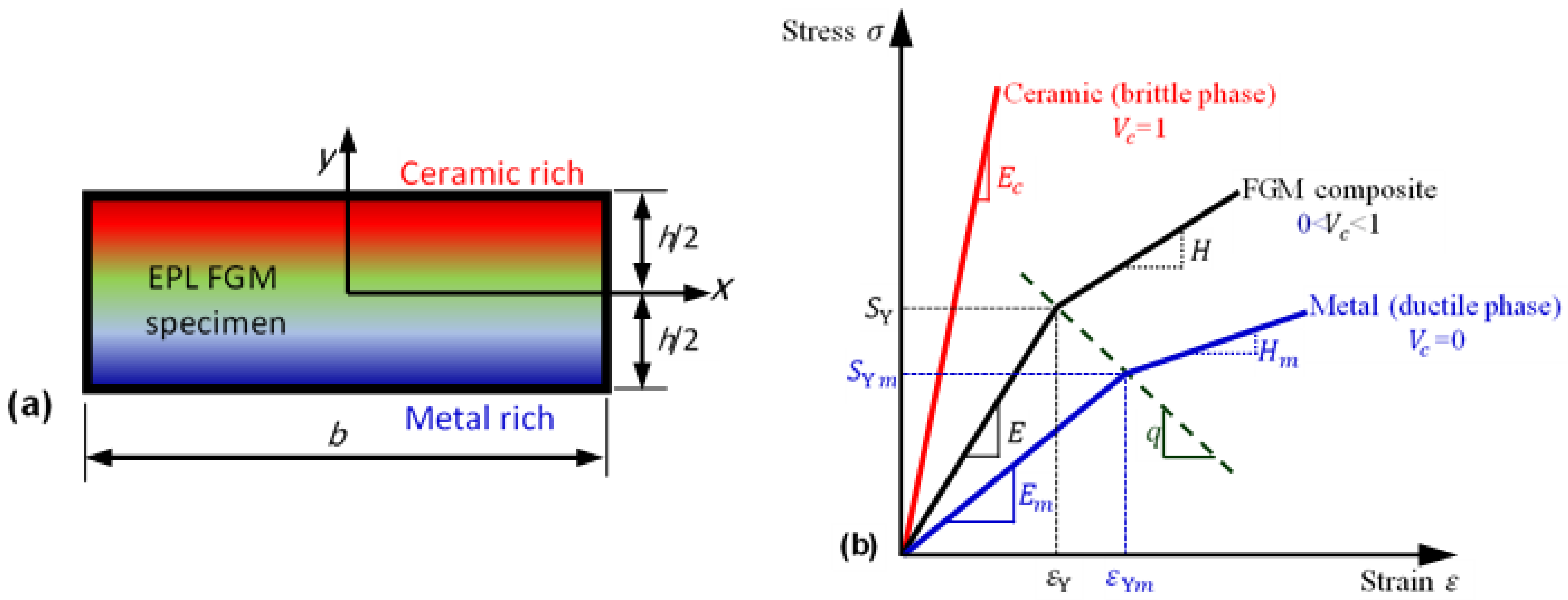
2. Elastoplastic Functionally Graded Material
3. Finite Element Modeling
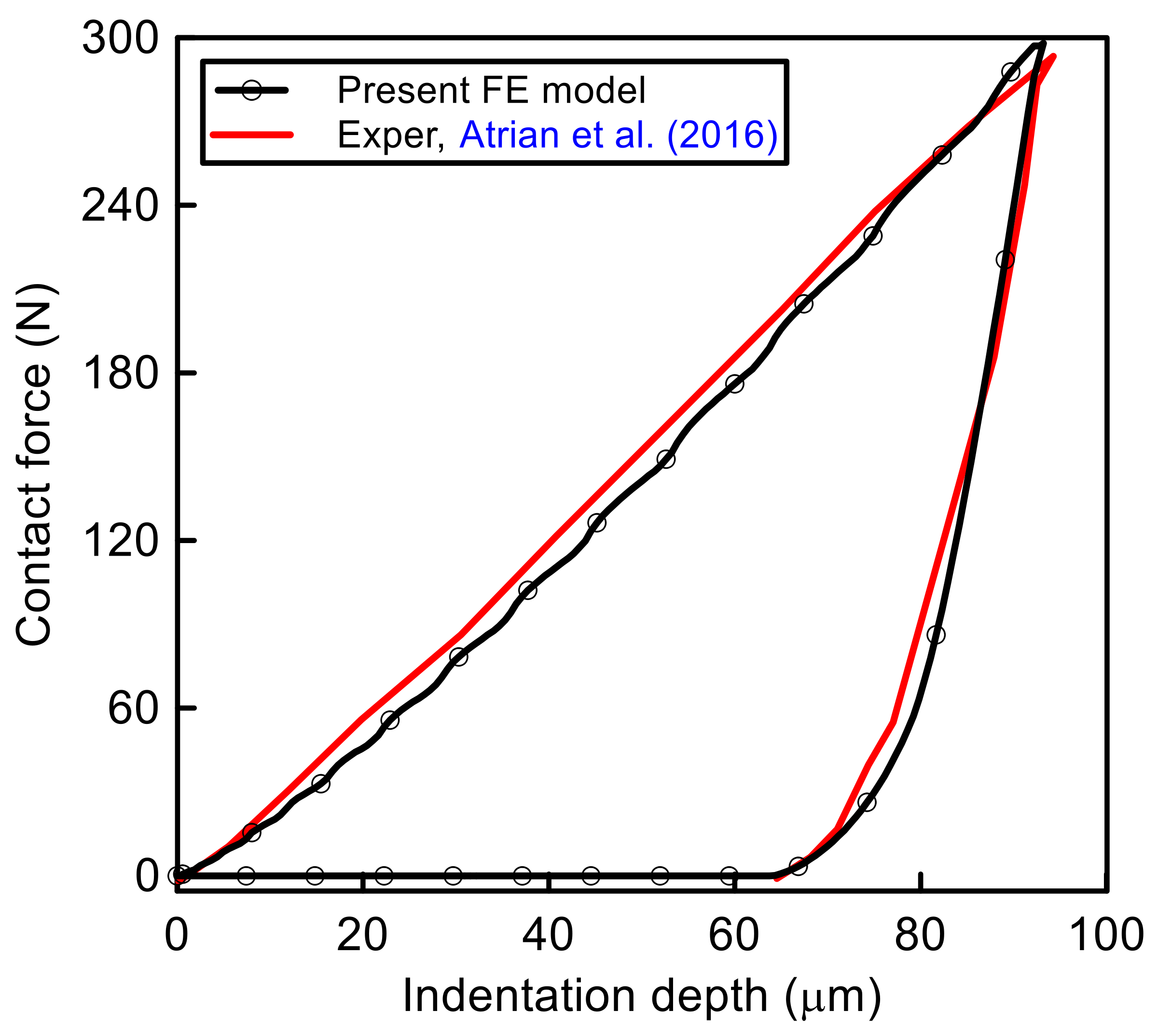
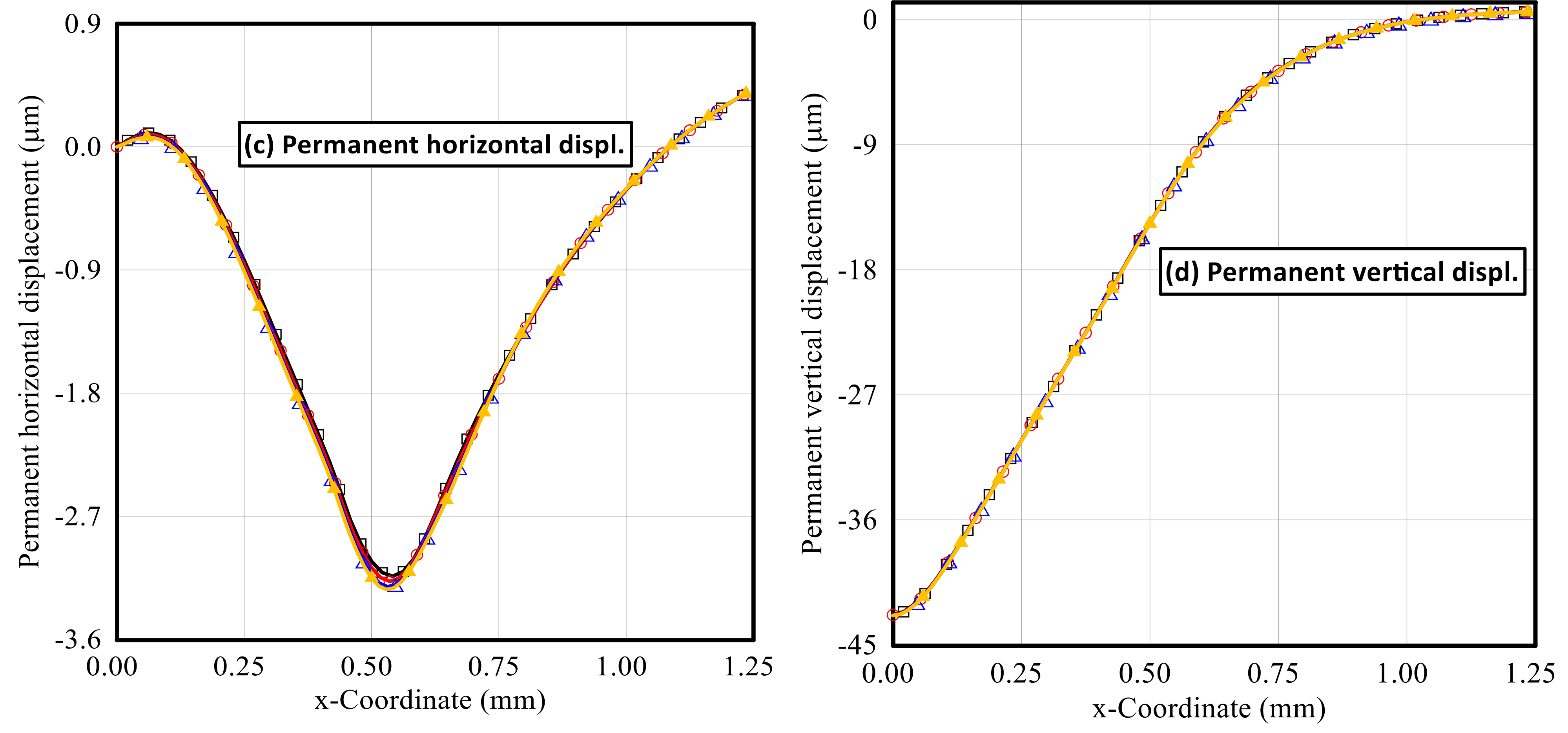
4. Validation and Convergence
5. Numerical Results and Discussions
6. Conclusions
- S-FGM distribution results in more compliant material than P-FGM distributions. Thus, a smaller indentation force and a larger enclosed loop size between the loading and unloading path are predicted, especially for gradient index k > 2.
- The von Mises equivalent stress at full was significantly affected by the material gradient index; it is increased by increasing the material gradient index for both S-FGM and P-FGM distributions.
- The von Mises residual stresses greatly affected by the material distributions and their gradient index. These residual stresses are increased with the increase in gradient index for both S-FGM and P-FGM distributions for 0 < k < 1.0 and decrease for k > 2.0.
- The total and elastic strain energies are dependent on both material distributions and their gradient indices. These energies are increased with the increase in gradient index for both S-FGM and P-FGM distributions. Additionally, for the same indentation depth, larger energy values are induced for P-FGM than those produced by S-FGM for all values of the material gradient indices.
- The dissipated energy due to the plastic deformation was significantly affected by the FGM distributions and their gradient index. This dissipated energy increases with the increase in gradient index for k = 0.25, 0.50, 1.0, and 2.0 and decreases with the increase in gradient index for k > 2 for both S-FGM and P-FGM distributions. Due to the increase in material compliance of S-FGM, a larger amount of dissipative energy is detected compared with the corresponding cases for P-FGM distributions.
- In general, the FGM characteristics’ distribution throughout the thickness direction significantly affects the mechanical behavior of the elastoplastic material under spherical indentation. This mechanical behavior could be controlled by selecting the suitable material distribution law with a controlled material gradient index.
- The study can be extended for different elastoplastic materials with a wide range of properties to generalize the developed empirical equation, so that the response of the general elastoplastic sigmoid FGM became well understood and predictable using these empirical relations.
Author Contributions
Funding
Institutional Review Board Statement
Informed Consent Statement
Data Availability Statement
Conflicts of Interest
References
- Alshorbagy, A.E.; Eltaher, M.; Mahmoud, F. Free vibration characteristics of a functionally graded beam by finite element method. Appl. Math. Model. 2011, 35, 412–425. [Google Scholar] [CrossRef]
- Esen, I.; Özarpa, C.; Eltaher, M.A. Free vibration of a cracked FG microbeam embedded in an elastic matrix and exposed to magnetic field in a thermal environment. Compos. Struct. 2021, 261, 113552. [Google Scholar] [CrossRef]
- Saleh, B.; Jiang, J.; Fathi, R.; Al-Hababi, T.; Xu, Q.; Wang, L.; Song, D.; Ma, A. 30 Years of functionally graded materials: An overview of manufacturing methods, Applications and Future Challenges. Compos. Part B Eng. 2020, 201, 108376. [Google Scholar] [CrossRef]
- Akış, T. Elastoplastic analysis of functionally graded spherical pressure vessels. Comput. Mater. Sci. 2009, 46, 545–554. [Google Scholar] [CrossRef]
- Vaghefi, R.; Hematiyan, M.; Nayebi, A. Three-dimensional thermo-elastoplastic analysis of thick functionally graded plates using the meshless local Petrov–Galerkin method. Eng. Anal. Bound. Elem. 2016, 71, 34–49. [Google Scholar] [CrossRef]
- Burzyński, S.; Chróścielewski, J.; Daszkiewicz, K.; Witkowski, W. Elastoplastic nonlinear FEM analysis of FGM shells of Cosserat type. Compos. Part B Eng. 2018, 154, 478–491. [Google Scholar] [CrossRef]
- Hasrati, E.; Ansari, R.; Rouhi, H. Elastoplastic postbuckling analysis of moderately thick rectangular plates using the variational differential quadrature method. Aerosp. Sci. Technol. 2019, 91, 479–493. [Google Scholar] [CrossRef]
- Vakil, S.; Zajkani, A. A micromechanically motivated lower order strain gradient model for plastic behavior of functionally graded crystalline micro beam structures. Mech. Mater. 2019, 137, 103135. [Google Scholar] [CrossRef]
- Vaghefi, R. Three-dimensional temperature-dependent thermo-elastoplastic bending analysis of functionally graded skew plates using a novel meshless approach. Aerosp. Sci. Technol. 2020, 104, 105916. [Google Scholar] [CrossRef]
- Zhang, L.; Lin, Q.; Chen, F.; Zhang, Y.; Yin, H. Micromechanical modeling and experimental characterization for the elastoplastic behavior of a functionally graded material. Int. J. Solids Struct. 2020, 206, 370–382. [Google Scholar] [CrossRef]
- Saeedi, S.; Kholdi, M.; Loghman, A.; Ashrafi, H.; Arefi, M. Thermo-elasto-plastic analysis of thick-walled cylinder made of functionally graded materials using successive approximation method. Int. J. Press. Vessel. Pip. 2021, 194, 104481. [Google Scholar] [CrossRef]
- Liu, Z.; Wei, G.; Qin, S.; Wang, Z. The elastoplastic analysis of functionally graded materials using a meshfree RRKPM. Appl. Math. Comput. 2022, 413, 126651. [Google Scholar] [CrossRef]
- Huang, H.; Han, Q. Elastoplastic buckling of axially loaded functionally graded material cylindrical shells. Compos. Struct. 2014, 117, 135–142. [Google Scholar] [CrossRef]
- Huang, H.; Han, Q. Stability of pressure-loaded functionally graded cylindrical shells with inelastic material properties. Thin-Walled Struct. 2015, 92, 21–28. [Google Scholar] [CrossRef]
- Zhang, Y.; Huang, H.; Han, Q. Buckling of elastoplastic functionally graded cylindrical shells under combined compression and pressure. Compos. Part B Eng. 2015, 69, 120–126. [Google Scholar] [CrossRef]
- Nguyen, D.K.; Nguyen, K.V.; Dinh, V.M.; Gan, B.S.; Alexandrov, S. Nonlinear bending of elastoplastic functionally graded ceramic-metal beams subjected to nonuniform distributed loads. Appl. Math. Comput. 2018, 333, 443–459. [Google Scholar] [CrossRef]
- Moita, J.S.; Soares, C.M.M.; Soares, C.A.M.; Ferreira, A.J. Elastoplastic and nonlinear analysis of functionally graded axisymmetric shell structures under thermal environment, using a conical frustum finite element model. Compos. Struct. 2019, 226, 111186. [Google Scholar] [CrossRef]
- Zhang, J.; Chen, L.; Lv, Y. Elastoplastic thermal buckling of functionally graded material beams. Compos. Struct. 2019, 224, 111014. [Google Scholar] [CrossRef]
- Zhu, B.; Cai, Y. A strain rate-dependent enhanced continuum model for elastic-plastic impact response of metal-ceramic functionally graded composites. Int. J. Impact Eng. 2019, 133, 103340. [Google Scholar] [CrossRef]
- Ma, J.; Ke, L.-L.; Wang, Y.-S. Frictionless contact of a functionally graded magneto-electro-elastic layered half-plane under a conducting punch. Int. J. Solids Struct. 2014, 51, 2791–2806. [Google Scholar] [CrossRef] [Green Version]
- Liu, T.-J.; Zhang, C.; Wang, Y.-S.; Xing, Y.-M. The axisymmetric stress analysis of double contact problem for functionally graded materials layer with arbitrary graded materials properties. Int. J. Solids Struct. 2016, 96, 229–239. [Google Scholar] [CrossRef]
- Vasiliev, A.S. Penetration of a spherical conductive punch into a piezoelectric half-space with a functionally graded coating. Int. J. Eng. Sci. 2019, 142, 230–241. [Google Scholar] [CrossRef]
- Hou, P.-F.; Zhang, W.-H.; Chen, J.-Y. Three-dimensional exact solutions of transversely isotropic coated structures under tilted circular flat punch contact. Int. J. Mech. Sci. 2019, 151, 471–497. [Google Scholar] [CrossRef]
- Asiri, S.; Wagih, A.; Eltaher, M. Predictive model for spherical indentation on elastoplastic nanocomposites: Loading and unloading behavior. Ceram. Int. 2019, 45, 3088–3100. [Google Scholar] [CrossRef]
- Chen, X.; Yue, Z. Contact mechanics of two elastic spheres reinforced by functionally graded materials (FGM) thin coatings. Eng. Anal. Bound. Elem. 2019, 109, 57–69. [Google Scholar] [CrossRef]
- Wagih, A.; Attia, M.; AbdelRahman, A.; Bendine, K.; Sebaey, T. On the indentation of elastoplastic functionally graded materials. Mech. Mater. 2019, 129, 169–188. [Google Scholar] [CrossRef]
- Melaibari, A.; Wagih, A.; Eltaher, M.A. Experimental and Numerical Investigation on Indentation of Orthotropic Microplates with Finite Thickness. Int. Polym. Process. 2020, 35, 314–325. [Google Scholar] [CrossRef]
- Daikh, A.A.; Houari, M.S.A.; Eltaher, M.A. A novel nonlocal strain gradient Quasi-3D bending analysis of sigmoid functionally graded sandwich nanoplates. Compos. Struct. 2020, 262, 113347. [Google Scholar] [CrossRef]
- Esen, I.; Abdelrahman, A.A.; Eltaher, M.A. On vibration of sigmoid/symmetric functionally graded nonlocal strain gradient nanobeams under moving load. Int. J. Mech. Mater. Des. 2021, 17, 721–742. [Google Scholar] [CrossRef]
- Melaibari, A.; Khoshaim, A.B.; Mohamed, S.A.; Eltaher, M.A. Static stability and of symmetric and sigmoid functionally graded beam under variable axial load. Steel Compos. Struct. 2020, 35, 671–685. [Google Scholar] [CrossRef]
- Jin, Z.-H.; Paulino, G.H.; Dodds, R.H. Cohesive fracture modeling of elastic–plastic crack growth in functionally graded materials. Eng. Fract. Mech. 2003, 70, 1885–1912. [Google Scholar] [CrossRef]
- Soh, A.K.; Bian, L.C.; Chakrabarty, J. Elastic/plastic buckling of a composite flat plate subjected to uniform edge compression. Thin-Walled Struct. 2000, 38, 247–265. [Google Scholar] [CrossRef]
- Giannakopoulos, A.; Suresh, S.; Finot, M.; Olsson, M. Elastoplastic analysis of thermal cycling: Layered materials with compositional gradients. Acta Met. Mater. 1995, 43, 1335–1354. [Google Scholar] [CrossRef]
- Williamson, R.; Rabin, B.H.; Drake, J.T. Finite element analysis of thermal residual stresses at graded ceramic-metal interfaces. Part I. Model description and geometrical effects. J. Appl. Phys. 1993, 74, 1310–1320. [Google Scholar] [CrossRef]
- Eltaher, M.; Attia, M.; Wagih, A. Predictive model for indentation of elasto-plastic functionally graded composites. Compos. Part B Eng. 2020, 197, 108129. [Google Scholar] [CrossRef]
- Atrian, A.; Majzoobi, G.; Nourbakhsh, S.; Galehdari, S.; Nejad, R.M. Evaluation of tensile strength of Al7075-SiC nanocomposite compacted by gas gun using spherical indentation test and neural networks. Adv. Powder Technol. 2016, 27, 1821–1827. [Google Scholar] [CrossRef]
- Wagih, A.; Maimí, P.; Blanco, N.; Trias, D. Predictive model for the spherical indentation of composite laminates with finite thickness. Compos. Struct. 2016, 153, 468–477. [Google Scholar] [CrossRef]


| Variable | U (mm) | k = 0 | k = 0.25 | k = 0.5 | k = 1.0 | k = 2.0 | k = 4.0 | k = 8.0 | |||||||
|---|---|---|---|---|---|---|---|---|---|---|---|---|---|---|---|
| P-FGM | S-FGM | P-FGM | S-FGM | P-FGM | S-FGM | P-FGM | S-FGM | P-FGM | S-FGM | P-FGM | S-FGM | P-FGM | S-FGM | ||
| Max. indentation pressure/103 (MPa) | 0.1 | 5.349 | 5.349 | 6.232 | 5.706 | 7.244 | 6.965 | 9.710 | 9.864 | 16.788 | 15.150 | 39.800 | 23.450 | 76.800 | 34.606 |
| 0.2 | 7.252 | 7.252 | 8.526 | 7.805 | 9.994 | 9.620 | 13.581 | 13.794 | 23.945 | 21.419 | 58.527 | 33.460 | 116.670 | 49.537 | |
| Max. indentation force (kN) | 0.1 | 1.751 | 1.751 | 1.957 | 1.850 | 2.188 | 2.137 | 2.744 | 2.777 | 4.275 | 3.892 | 8.954 | 5.552 | 16.030 | 16.030 |
| 0.2 | 4.348 | 4.348 | 4.920 | 4.662 | 5.570 | 5.456 | 7.130 | 7.218 | 11.480 | 10.280 | 25.160 | 14.820 | 47.060 | 20.340 | |
| Max. permanent horizontal displacement (µm) | 0.1 | −1.032 | −1.032 | −1.301 | −1.148 | −1.460 | −1.432 | −1.489 | −1.489 | −1.152 | −1.230 | −0.542 | −0.939 | −0.063 | −0.658 |
| 0.2 | −3.129 | −3.129 | −3.246 | −3.015 | −3.215 | −3.136 | −2.912 | −2.902 | −2.052 | −2.269 | −0.996 | −1.831 | −0.078 | −1.814 | |
| Max. permanent vertical displacement (µm) | 0.1 | −33.70 | −33.70 | −29.38 | −32.00 | −25.67 | −26.70 | −19.74 | −19.48 | −11.83 | −13.02 | −4.17 | −8.34 | −0.39 | −5.19 |
| 0.2 | −56.56 | −56.56 | −49.09 | −53.09 | −42.87 | −44.02 | −32.86 | −32.42 | −19.90 | −22.27 | −7.60 | −15.33 | −0.62 | −12.42 | |
| Max. von Mises stress (10 MPa) | 0.1 | 280.1 | 280.1 | 332.3 | 303.4 | 392.3 | 376.5 | 538.4 | 548.9 | 967.1 | 866.0 | 2460 | 1380 | 5342 | 2456 |
| 0.2 | 394.2 | 394.2 | 469.5 | 428.6 | 556.5 | 535.4 | 771.7 | 782.5 | 1405 | 1240 | 3642 | 1972 | 3645 | 3001 | |
| Max residual von Mises stress (10 MPa) | 0.1 | 38.6 | 38.6 | 38.9 | 39.6 | 42.4 | 45.1 | 43.3 | 42.2 | 42.0 | 42.1 | 33.0 | 10.9 | 7.51 | 4.33 |
| 0.2 | 436.2 | 436.2 | 45.7 | 43.9 | 47.2 | 46.5 | 49.0 | 48.6 | 47.8 | 48.4 | 37.4 | 45.4 | 37.3 | 42.2 | |
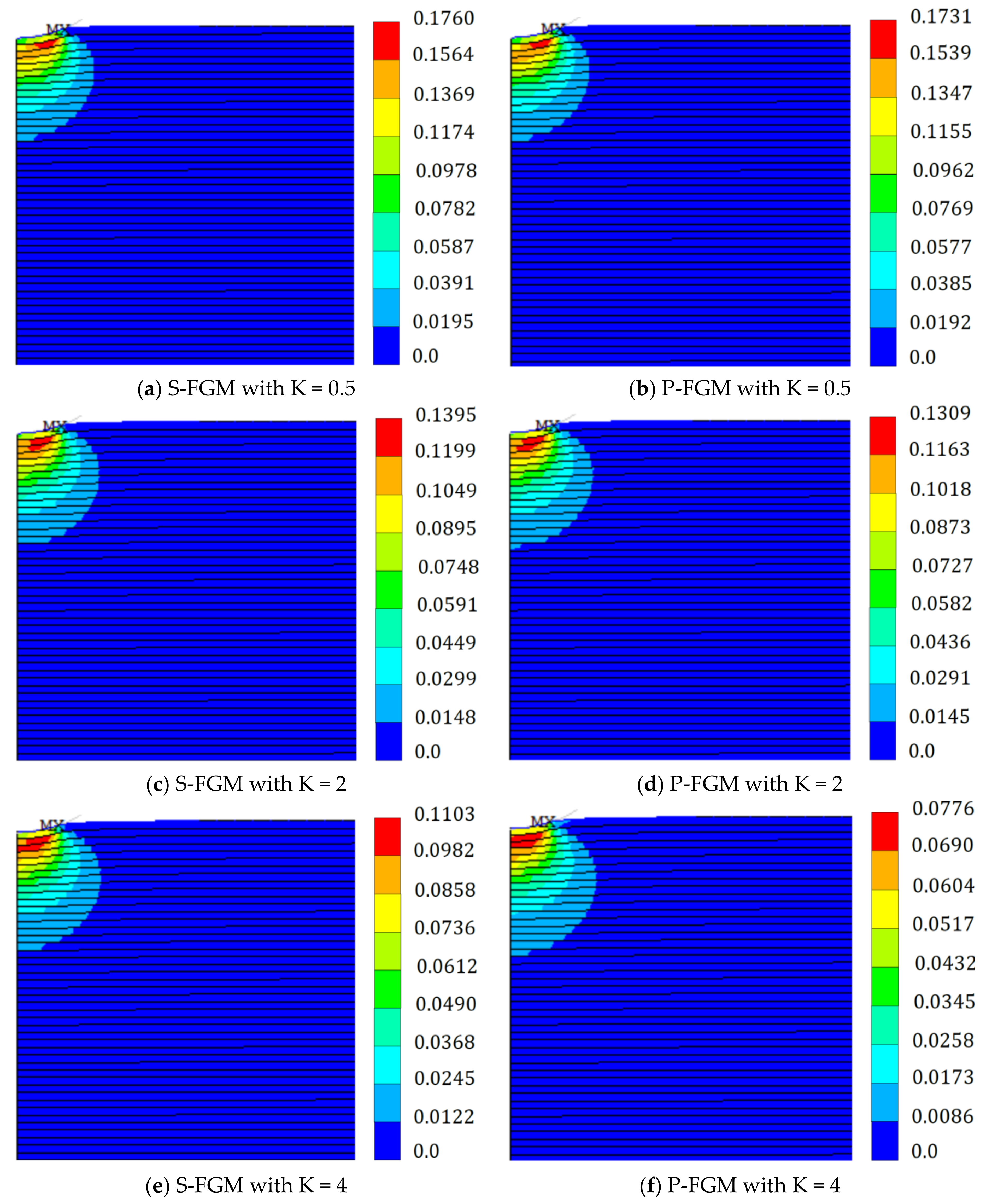
| Effective plastic strain | 0.1 | 0.1898 | 0.1898 | 0.1875 | 0.1812 | 0.1731 | 0.1760 | 0.1582 | 0.1573 | 0.1309 | 0.1349 | 0.0776 | 0.1104 | 0.0103 | 0.0985 |
| 0.2 | 0.2727 | 0.2727 | 0.2587 | 0.2701 | 0.2051 | 0.2515 | 0.2238 | 0.2229 | 0.1870 | 0.1913 | 0.1151 | 0.1574 | 0.1151 | 0.1210 | |
| Total energy (N × mm) | 0.1 | 75.69 | 75.69 | 83.95 | 79.60 | 93.28 | 91.13 | 115.54 | 116.88 | 176.37 | 161.56 | 358.78 | 227.82 | 626.67 | 626.67 |
| 0.2 | 376.07 | 376.07 | 422.36 | 399.72 | 474.66 | 464.06 | 600.04 | 607.58 | 947.29 | 856.98 | 2021.03 | 1227.98 | 3687.05 | 1694.68 | |
| Elastic energy (N × mm) | 0.1 | 30.64 | 30.64 | 37.46 | 33.10 | 45.41 | 43.08 | 65.11 | 66.35 | 122.95 | 109.18 | 313.55 | 176.10 | 618.93 | 618.93 |
| 0.2 | 167.39 | 167.39 | 206.54 | 184.45 | 251.98 | 241.08 | 364.13 | 370.77 | 691.95 | 605.71 | 1786.40 | 965.82 | 3654.89 | 1410.82 | |
| Plastic dissipative energy (N × mm) | 0.1 | 45.047 | 45.047 | 46.489 | 46.498 | 47.863 | 48.056 | 50.426 | 50.532 | 53.418 | 52.380 | 45.229 | 51.717 | 7.742 | 7.742 |
| 0.2 | 208.68 | 208.68 | 215.82 | 215.27 | 222.69 | 222.99 | 235.91 | 236.82 | 255.34 | 251.27 | 234.63 | 262.16 | 32.15 | 283.86 | |
Publisher’s Note: MDPI stays neutral with regard to jurisdictional claims in published maps and institutional affiliations. |
© 2022 by the authors. Licensee MDPI, Basel, Switzerland. This article is an open access article distributed under the terms and conditions of the Creative Commons Attribution (CC BY) license (https://creativecommons.org/licenses/by/4.0/).
Share and Cite
Eltaher, M.A.; Wagih, A.; Melaibari, A.; Alsoruji, G.S.; Attia, M.A. Elastoplastic Indentation Response of Sigmoid/Power Functionally Graded Ceramics Structures. Polymers 2022, 14, 1225. https://doi.org/10.3390/polym14061225
Eltaher MA, Wagih A, Melaibari A, Alsoruji GS, Attia MA. Elastoplastic Indentation Response of Sigmoid/Power Functionally Graded Ceramics Structures. Polymers. 2022; 14(6):1225. https://doi.org/10.3390/polym14061225
Chicago/Turabian StyleEltaher, Mohamed A., Ahmed Wagih, Ammar Melaibari, Ghazi S. Alsoruji, and Mohamed A. Attia. 2022. "Elastoplastic Indentation Response of Sigmoid/Power Functionally Graded Ceramics Structures" Polymers 14, no. 6: 1225. https://doi.org/10.3390/polym14061225