
Hybrid Printing Method of Polymer and Continuous Fiber-Reinforced Thermoplastic Composites (CFRTPCs) for Pipes through Double-Nozzle Five-Axis Printer

 ,
,  and
and
Abstract
:1. Introduction
2. Experimental Platform and Materials
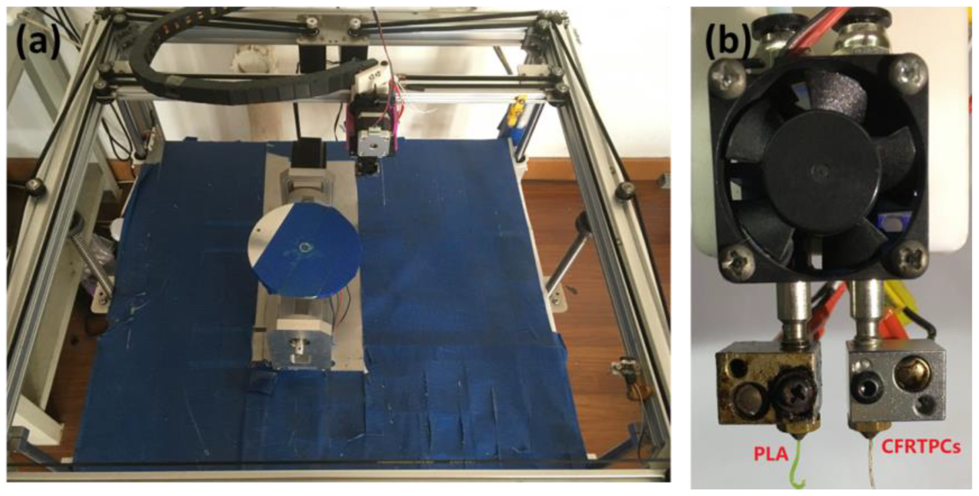
2.1. Experimental Platform
2.2. Materials
2.3. The Double-Nozzle Setting
3. CFRTPC-Reinforced Printing Methodology
3.1. Part Modeling and Feature Recognition
3.2. Technological Process
3.3. Printing Path Planning
3.3.1. Printing Path Planning of the Base Structure
3.3.2. Printing Path Planning of CFRTPC-Reinforced Curve Surface
4. Mechanical Property Test
4.1. Pressure Test
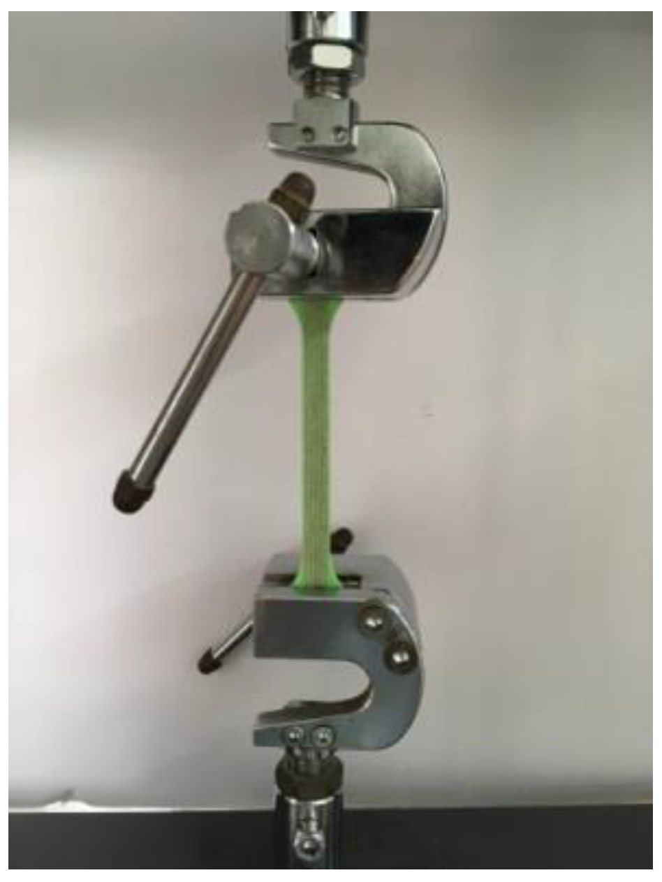
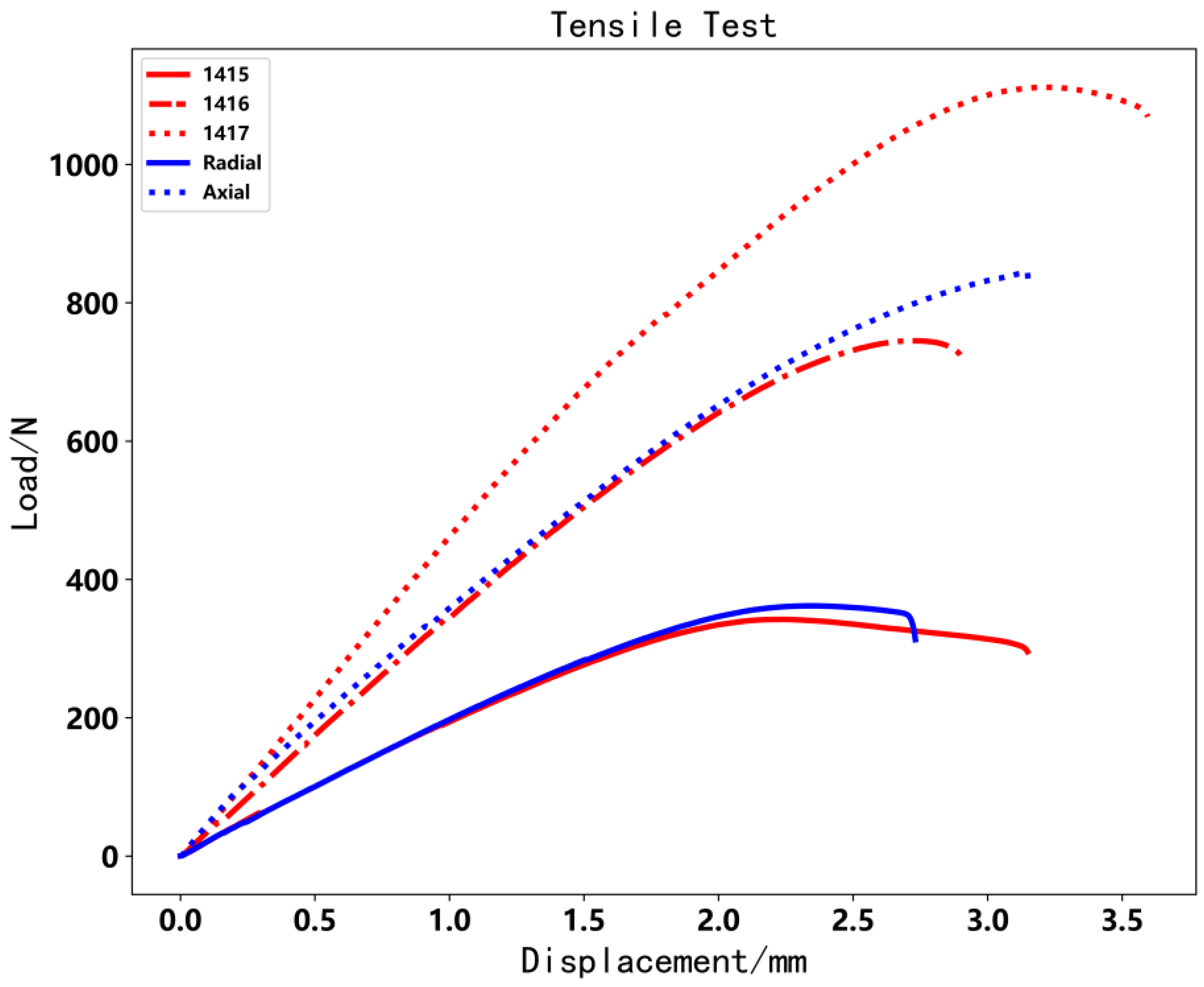
4.2. Tensile Test
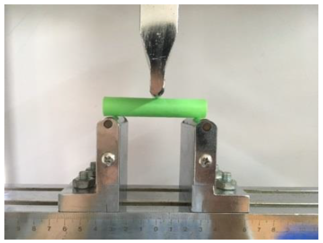
4.3. Three-Point Bending Test
5. Conclusions
Author Contributions
Funding
Institutional Review Board Statement
Informed Consent Statement
Acknowledgments
Conflicts of Interest
References
- Mannoor, M.S.; Jiang, Z.; James, T.; Kong, Y.L.; Malatesta, K.A.; Soboyejo, W.O.; Verma, N.; Gracias, D.; McAlpine, M. 3D printed bionic ears. Nano Lett. 2013, 13, 2634–2639. [Google Scholar] [CrossRef] [PubMed] [Green Version]
- Huang, W.-C.; Chang, K.-P.; Wu, P.-H.; Wu, C.-H.; Lin, C.-C.; Chuang, C.-S.; Lin, D.-Y.; Liu, S.-H.; Horng, J.-B.; Tsau, F.-H. 3D printing optical engine for controlling material microstructure. Phys. Procedia 2016, 83, 847–853. [Google Scholar] [CrossRef] [Green Version]
- Crump, S.S. Apparatus and Method for Creating Three-Dimensional Objects. U.S. Patent 5,121,329, 9 June 1992. [Google Scholar]
- Chen, Q.; Boisse, P.; Park, C.H.; Saouab, A.; Bréard, J. Intra/inter-ply shear behaviors of continuous fiber reinforced thermoplastic composites in thermoforming processes. Compos. Struct. 2011, 93, 1692–1703. [Google Scholar] [CrossRef]
- Tekinalp, H.L.; Kunc, V.; Velezgarcia, G.M.; Duty, C.E.; Love, L.J.; Naskar, A.K.; Blue, C.A.; Ozcan, S. Highly oriented carbon fiber–polymer composites via additive manufacturing. Compos. Sci. Technol. 2014, 105, 144–150. [Google Scholar] [CrossRef] [Green Version]
- Tian, X.; Liu, T.; Yang, C.; Wang, Q.; Li, D. Interface and performance of 3D printed continuous carbon fiber reinforced PLA composites. Compos. Part A Appl. Sci. Manuf. 2016, 88, 198–205. [Google Scholar] [CrossRef]
- Tian, X.; Liu, T.; Wang, Q.; Dilmurat, A.; Li, D.; Ziegmann, G. Recycling and remanufacturing of 3D printed continuous carbon fiber reinforced PLA composites. J. Clean. Prod. 2017, 142, 1609–1618. [Google Scholar] [CrossRef]
- Yao, Y.; Li, M.; Lackner, M.; Herfried, L. A Continuous Fiber-Reinforced Additive Manufacturing Processing Based on PET Fiber and PLA. Materials 2020, 13, 3044. [Google Scholar] [CrossRef]
- Yao, X.; Luan, C.; Zhang, D.; Lan, L.; Fu, J. Evaluation of Carbon Fiber-Embedded 3D Printed Structures for Strengthening and Structural-Health Monitoring. Mater. Des. 2017, 114, 424–432. [Google Scholar] [CrossRef]
- Zhang, H.; Yang, D.; Sheng, Y. Performance-driven 3D Printing of Continuous Curved Carbon Fibre Reinforced Polymer Composites: A Preliminary Numerical Study. Compos. Part B Eng. 2018, 151, 256–264. [Google Scholar] [CrossRef]
- Hao, W.; Liu, Y.; Zhou, H.; Chen, H.; Fang, D. Preparation and Characterization of 3D Printed Continuous Carbon Fiber Reinforced Thermosetting Composites. Polym. Test. 2018, 65, 29–34. [Google Scholar] [CrossRef]
- Hu, Q.; Duan, Y.; Zhang, H.; Liu, D.; Yan, B.; Peng, F. Manufacturing and 3D Printing of Continuous Carbon Fiber Prepreg Filament. J. Mater. Sci. 2018, 53, 1887–1898. [Google Scholar] [CrossRef]
- Luan, C.; Yao, X.; Liu, C.; Lan, L.; Fu, J. Self-monitoring continuous carbon fiber reinforced thermoplastic based on dual-material three-dimensional printing integration process. Carbon 2018, 140, 100–111. [Google Scholar] [CrossRef]
- Sugiyama, K.; Matsuzaki, R.; Ueda, M.; Todoroki, A.; Hirano, Y. 3D printing of composite sandwich structures using continuous carbon fiber and fiber tension. Compos. Part A Appl. Sci. Manuf. 2018, 113, 114–121. [Google Scholar] [CrossRef]
- Zhang, H.; Liu, D.; Huang, T.; Hu, Q.; Lammer, H. Three-Dimensional Printing of Continuous Flax Fiber-Reinforced Thermoplastic Composites by Five-Axis Machine. Materials 2020, 13, 1678. [Google Scholar] [CrossRef] [Green Version]
- Zhang, H.; Zhong, W.; Hu, Q.; Aburaia, M.; Gonzalez-Gutierrez, J.; Lammer, H. Research and Implementation of Axial 3D Printing Method for PLA Pipes. Appl. Sci. 2020, 10, 4680. [Google Scholar] [CrossRef]
- Wang, M.; Zhang, H.; Hu, Q.; Liu, D.; Lammer, H. Research and implementation of a non-supporting 3D printing method based on 5-axis dynamic slice algorithm. Robot. Comput. Integr. Manuf. 2019, 57, 496–505. [Google Scholar] [CrossRef]
- Huang, B.; Singamneni, S.B. Curved Layer Adaptive Slicing (CLAS) for Fused Deposition Modelling. Rapid Prototyp. J. 2015, 21, 354–367. [Google Scholar] [CrossRef]
- Huang, B.; Singamneni, S. A Mixed-Layer Approach Combining Both Flat and Curved Layer Slicing for Fused Deposition Modelling. Proc. Inst. Mech. Eng. Part B-J. Eng. Manuf. 2014, 229, 2238–2249. [Google Scholar] [CrossRef]
- Zhao, H.-M.; He, Y.; Fu, J.-Z.; Qiu, J.-J. Inclined layer printing for fused deposition modeling without assisted supporting structure. Robot. Comput. Manuf. 2018, 51, 1–13. [Google Scholar] [CrossRef]
- Grutle, Ø.K. 5-Axis 3D Printer. Master’s Thesis, Universitetet i Oslo, Oslo, Norway, 2015. [Google Scholar]
- Kawagishi, K.; Umetani, S.; Tanaka, K.; Ametani, E.; Morimoto, Y.; Takasugi, K. Development of Four-Axis 3D Printer with Fused Deposition Modeling Technology. Int. J. Autom. Technol. 2017, 11, 278–286. [Google Scholar] [CrossRef]
- Keating, S.; Oxman, N. Compound fabrication: A multi-functional robotic platform for digital design and fabrication. Robot. Comput. Manuf. 2013, 29, 439–448. [Google Scholar] [CrossRef]
- Available online: https://markforged.com/mark-two (accessed on 15 November 2020).
- Colding, T.; Minicozzi, W.; Pedersen, E. Mean curvature flow. Bull. Am. Phys. Soc. 2015, 52, 297–333. [Google Scholar] [CrossRef] [Green Version]


| Test Code | 1415 | 1416 | 1417 | Radial | Axial |
|---|---|---|---|---|---|
| Maximal load/N | 120 | 240 | 420 | 370 | 130 |
| Mass/g | 0.83 | 1.38 | 1.90 | 1.42 | 1.40 |
| Test Code | 1415 | 1416 | 1417 | Radial | Axial |
|---|---|---|---|---|---|
| Maximal Load/N | 342.1 | 744.9 | 1111.4 | 361.7 | 844.5 |
| Test Code | 1415 | 1416 | 1417 | Radial | Axial |
|---|---|---|---|---|---|
| Maximal load/N | 141.0 | 199.9 | 648.5 | 332.6 | 324.3 |
Publisher’s Note: MDPI stays neutral with regard to jurisdictional claims in published maps and institutional affiliations. |
© 2022 by the authors. Licensee MDPI, Basel, Switzerland. This article is an open access article distributed under the terms and conditions of the Creative Commons Attribution (CC BY) license (https://creativecommons.org/licenses/by/4.0/).
Share and Cite
Zhang, H.; Lei, X.; Hu, Q.; Wu, S.; Aburaia, M.; Gonzalez-Gutierrez, J.; Lammer, H. Hybrid Printing Method of Polymer and Continuous Fiber-Reinforced Thermoplastic Composites (CFRTPCs) for Pipes through Double-Nozzle Five-Axis Printer. Polymers 2022, 14, 819. https://doi.org/10.3390/polym14040819
Zhang H, Lei X, Hu Q, Wu S, Aburaia M, Gonzalez-Gutierrez J, Lammer H. Hybrid Printing Method of Polymer and Continuous Fiber-Reinforced Thermoplastic Composites (CFRTPCs) for Pipes through Double-Nozzle Five-Axis Printer. Polymers. 2022; 14(4):819. https://doi.org/10.3390/polym14040819
Chicago/Turabian StyleZhang, Haiguang, Xu Lei, Qingxi Hu, Shichao Wu, Mohamed Aburaia, Joamin Gonzalez-Gutierrez, and Herfried Lammer. 2022. "Hybrid Printing Method of Polymer and Continuous Fiber-Reinforced Thermoplastic Composites (CFRTPCs) for Pipes through Double-Nozzle Five-Axis Printer" Polymers 14, no. 4: 819. https://doi.org/10.3390/polym14040819