

Electrospinning vs. Electro-Assisted Solution Blow Spinning for Fabrication of Fibrous Scaffolds for Tissue Engineering
 , , , , , , , , ,
Abstract
:1. Introduction
2. Materials and Methods
2.1. Materials
2.2. Fabrication and Physical-Chemical Properties of the Fibrous Materials
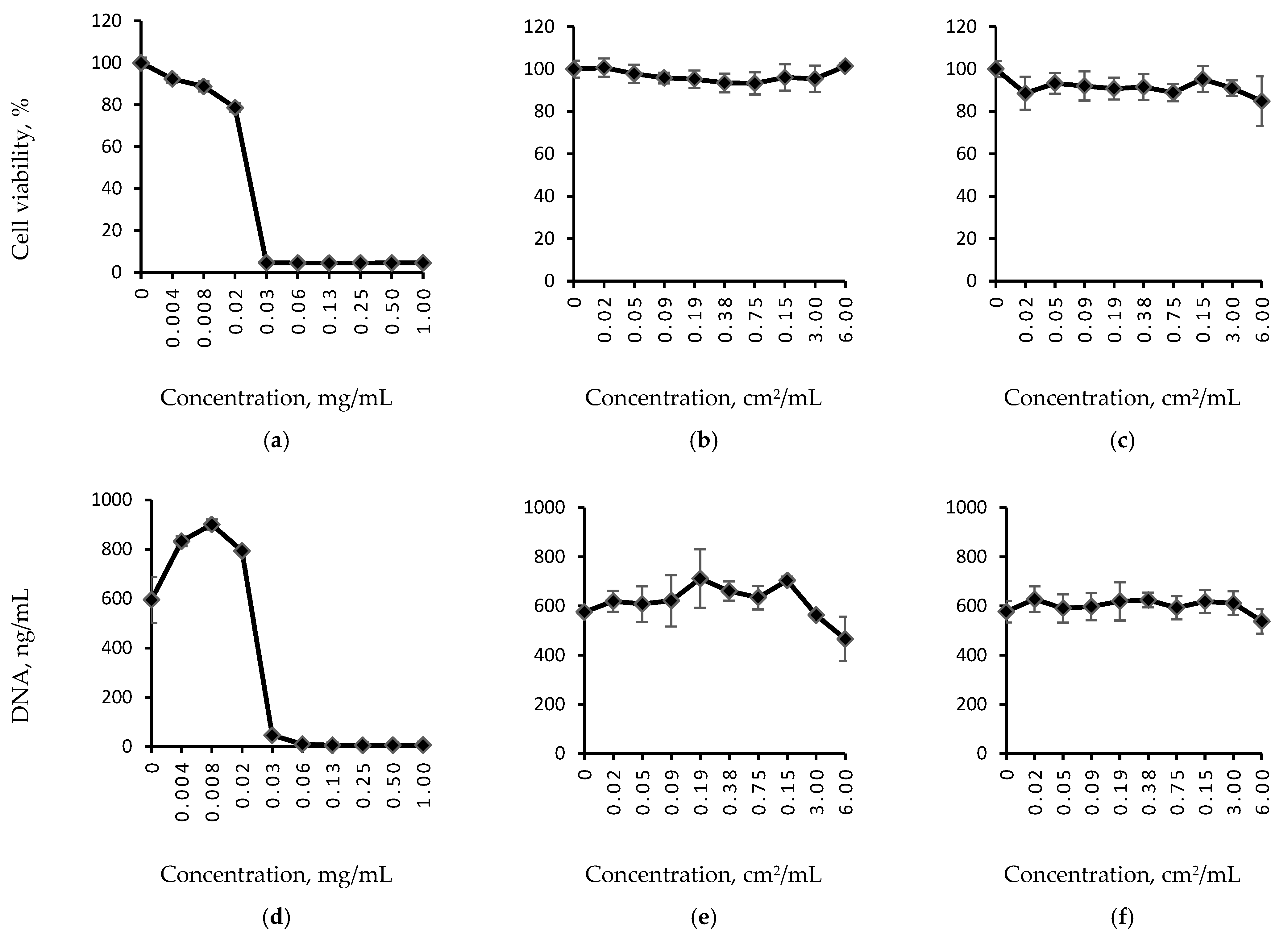
2.3. In Vitro Cell Biocompatibility of Non-Woven Fibrous Mats
2.3.1. Cell Culture
2.3.2. Material Cytocompatibility via Extract Test
2.3.3. Contact Cytocompatibility of the Fibrous Materials
3. Results
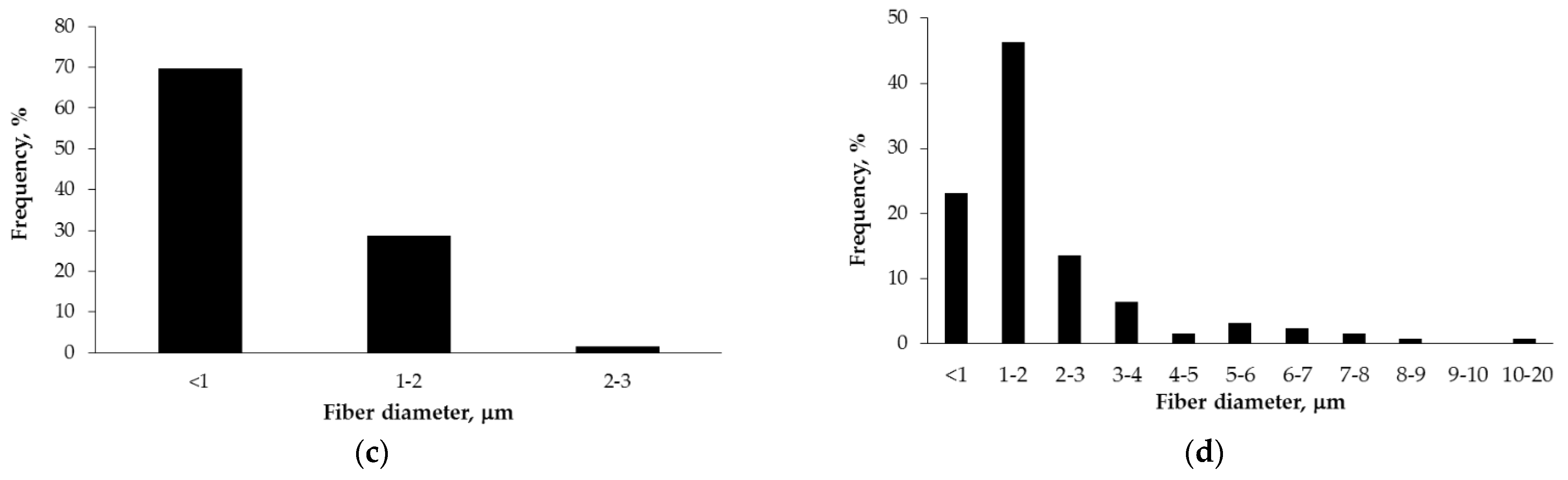
3.1. Morphology and Physical-Chemical Properties of the Fibrous Materials
3.1.1. SEM Microscopy of the Fibrous Materials
3.1.2. Surface Properties of the Fibrous Materials
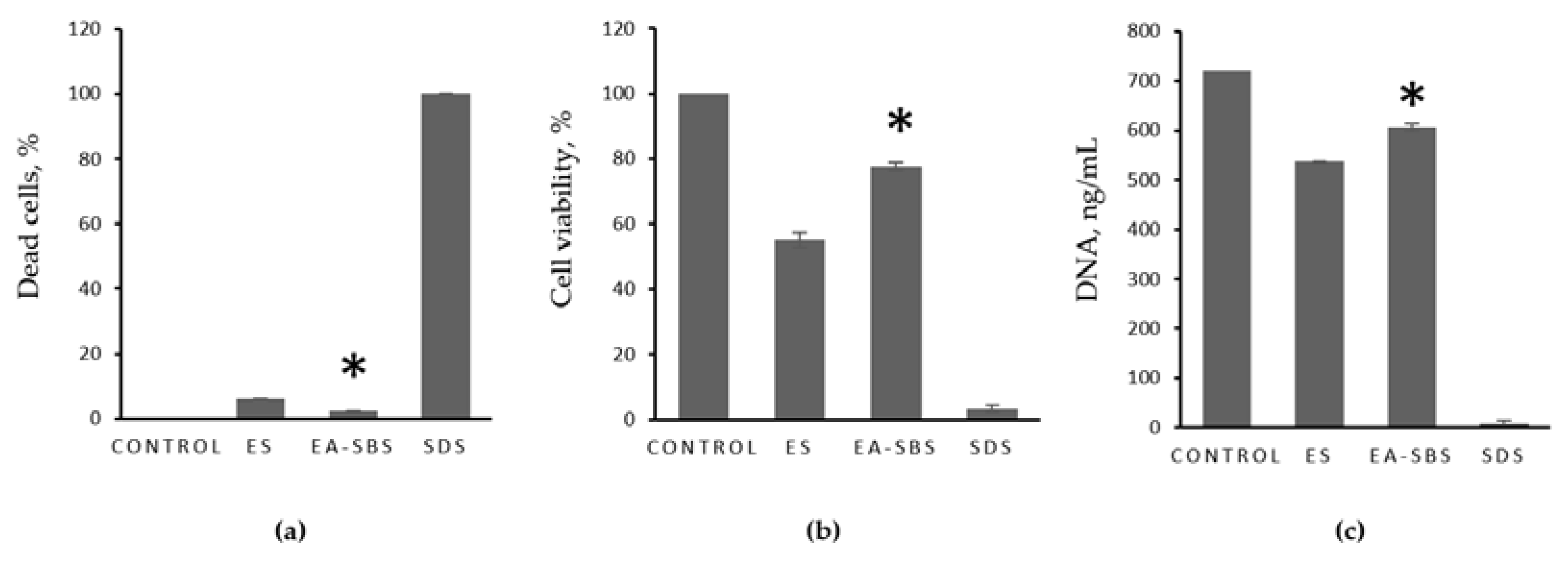
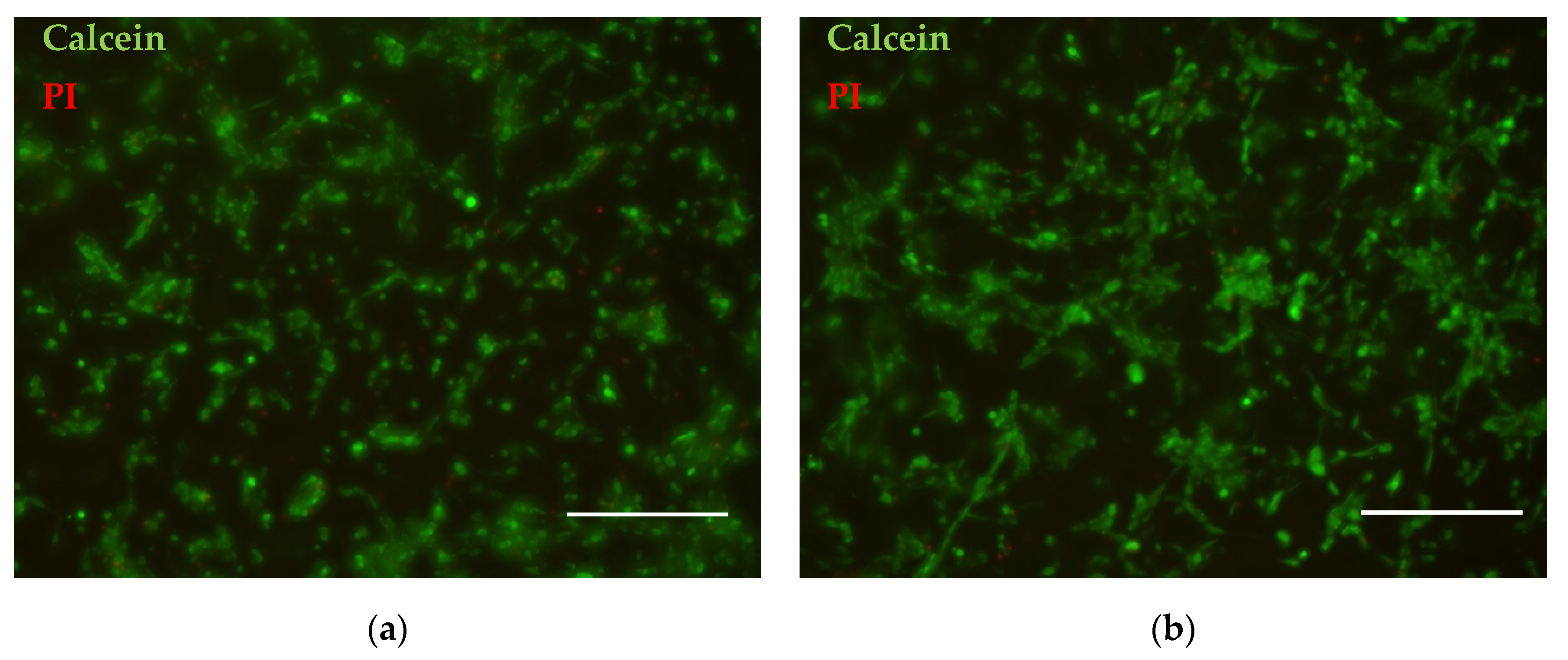
3.2. Cytocompatibility of the Non-Woven Mats
4. Discussion
5. Conclusions
Supplementary Materials
Author Contributions
Funding
Institutional Review Board Statement
Informed Consent Statement
Data Availability Statement
Conflicts of Interest
References
- Rahmati, M.; Mills, D.K.; Urbanska, A.M.; Saeb, M.R.; Venugopal, J.R.; Ramakrishna, S.; Mozafari, M. Electrospinning for tissue engineering applications. Prog. Mater. Sci. 2021, 117, 100721. [Google Scholar] [CrossRef]
- Kitsara, M.; Agbulut, O.; Kontziampasis, D.; Chen, Y.; Menasché, P. Fibers for hearts: A critical review on electrospinning for cardiac tissue engineering. Acta Biomater. 2017, 48, 20–40. [Google Scholar] [CrossRef] [PubMed]
- Sameen, D.E.; Ahmed, S.; Lu, R.; Li, R.; Dai, J.; Qin, W.; Zhang, Q.; Li, S.; Liu, Y. Electrospun nanofibers food packaging: Trends and applications in food systems. Crit. Rev. Food Sci. Nutr. 2022, 62, 6238–6251. [Google Scholar] [CrossRef] [PubMed]
- Feng, X.; Li, J.; Zhang, X.; Liu, T.; Ding, J.; Chen, X. Electrospun polymer micro/nanofibers as pharmaceutical repositories for healthcare. J. Control. Release 2019, 302, 19–41. [Google Scholar] [CrossRef]
- Arida, I.A.; Ali, I.H.; Nasr, M.; El-Sherbiny, I.M. Electrospun polymer-based nanofiber scaffolds for skin regeneration. J. Drug Deliv. Sci. Technol. 2021, 64, 102623. [Google Scholar] [CrossRef]
- Kishan, A.P.; Cosgriff-Hernandez, E.M. Recent advancements in electrospinning design for tissue engineering applications: A review. J. Biomed. Mater. Res. Part A 2017, 105, 2892–2905. [Google Scholar] [CrossRef]
- Khorshidi, S.; Solouk, A.; Mirzadeh, H.; Mazinani, S.; Lagaron, J.M.; Sharifi, S.; Ramakrishna, S. A review of key challenges of electrospun scaffolds for tissue-engineering applications. J. Tissue Eng. Regen. Med. 2016, 10, 715–738. [Google Scholar] [CrossRef]
- Muerza-Cascante, M.L.; Haylock, D.; Hutmacher, D.W.; Dalton, P.D. Melt Electrospinning and Its Technologization in Tissue Engineering. Tissue Eng. Part B Rev. 2015, 21, 187–202. [Google Scholar] [CrossRef]
- Maleki, H.; Azimi, B.; Ismaeilimoghadam, S.; Danti, S. Poly(lactic acid)-Based Electrospun Fibrous Structures for Biomedical Applications. Appl. Sci. 2022, 12, 3192. [Google Scholar] [CrossRef]
- Singh, Y.P.; Dasgupta, S.; Nayar, S.; Bhaskar, R. Optimization of electrospinning process & parameters for producing defect-free chitosan/polyethylene oxide nanofibers for bone tissue engineering. J. Biomater. Sci. Polym. Ed. 2020, 31, 781–803. [Google Scholar] [CrossRef]
- Li, Q.; Wang, X.; Lou, X.; Yuan, H.; Tu, H.; Li, B.; Zhang, Y. Genipin-crosslinked electrospun chitosan nanofibers: Determination of crosslinking conditions and evaluation of cytocompatibility. Carbohydr. Polym. 2015, 130, 166–174. [Google Scholar] [CrossRef] [PubMed]
- Qasim, S.; Zafar, M.; Najeeb, S.; Khurshid, Z.; Shah, A.; Husain, S.; Rehman, I. Electrospinning of Chitosan-Based Solutions for Tissue Engineering and Regenerative Medicine. Int. J. Mol. Sci. 2018, 19, 407. [Google Scholar] [CrossRef] [PubMed] [Green Version]
- McClellan, P.; Landis, W.J. Recent Applications of Coaxial and Emulsion Electrospinning Methods in the Field of Tissue Engineering. Biores. Open Access 2016, 5, 212–227. [Google Scholar] [CrossRef] [PubMed] [Green Version]
- Duan, G.; Greiner, A. Air-Blowing-Assisted Coaxial Electrospinning toward High Productivity of Core/Sheath and Hollow Fibers. Macromol. Mater. Eng. 2019, 304, 1800669. [Google Scholar] [CrossRef]
- Daristotle, J.L.; Behrens, A.M.; Sandler, A.D.; Kofinas, P. A Review of the Fundamental Principles and Applications of Solution Blow Spinning. ACS Appl. Mater. Interfaces 2016, 8, 34951–34963. [Google Scholar] [CrossRef] [Green Version]
- Gao, Y.; Zhang, J.; Su, Y.; Wang, H.; Wang, X.X.; Huang, L.P.; Yu, M.; Ramakrishna, S.; Long, Y.Z. Recent progress and challenges in solution blow spinning. Mater. Horizons 2021, 8, 426–446. [Google Scholar] [CrossRef]
- Lauricella, M.; Succi, S.; Zussman, E.; Pisignano, D.; Yarin, A.L. Models of polymer solutions in electrified jets and solution blowing. Rev. Mod. Phys. 2020, 92, 035004. [Google Scholar] [CrossRef]
- Choi, M.; Kim, J. Development of Coaxial Air-blown Electrospinning Process for Manufacturing Non-woven Nanofiber. II. Intelligent Modeling. Fibers Polym. 2019, 20, 1883–1892. [Google Scholar] [CrossRef]
- Cao, L.; Liu, Q.; Ren, J.; Chen, W.; Pei, Y.; Kaplan, D.L.; Ling, S. Electro-Blown Spun Silk/Graphene Nanoionotronic Skin for Multifunctional Fire Protection and Alarm. Adv. Mater. 2021, 33, 2102500. [Google Scholar] [CrossRef]
- Al Rai, A.; Stojanovska, E.; Fidan, G.; Yetgin, E.; Polat, Y.; Kilic, A.; Demir, A.; Yilmaz, S. Structure and performance of electroblown PVDF-based nanofibrous electret filters. Polym. Eng. Sci. 2020, 60, 1186–1193. [Google Scholar] [CrossRef]
- Sadeghzadeh, A.; Bazgir, S.; Shirazi, M.M.A. Fabrication and characterization of a novel hydrophobic polystyrene membrane using electroblowing technique for desalination by direct contact membrane distillation. Sep. Purif. Technol. 2020, 239, 116498. [Google Scholar] [CrossRef]
- Aminyan, R.; Bazgir, S. Fabrication and characterization of nanofibrous polyacrylic acid superabsorbent using gas-assisted electrospinning technique. React. Funct. Polym. 2019, 141, 133–144. [Google Scholar] [CrossRef]
- Holopainen, J.; Ritala, M. Rapid production of bioactive hydroxyapatite fibers via electroblowing. J. Eur. Ceram. Soc. 2016, 36, 3219–3224. [Google Scholar] [CrossRef]
- Dias, Y.J.; Robles, J.R.; Sinha-Ray, S.; Abiade, J.; Pourdeyhimi, B.; Niemczyk-Soczynska, B.; Kolbuk, D.; Sajkiewicz, P.; Yarin, A.L. Solution-Blown Poly(hydroxybutyrate) and ε-Poly-L-lysine Submicro- and Microfiber-Based Sustainable Nonwovens with Antimicrobial Activity for Single-Use Applications. ACS Biomater. Sci. Eng. 2021, 7, 3980–3992. [Google Scholar] [CrossRef]
- Rampichová, M.; Chvojka, J.; Jenčová, V.; Kubíková, T.; Tonar, Z.; Erben, J.; Buzgo, M.; Daňková, J.; Litvinec, A.; Vocetková, K.; et al. The combination of nanofibrous and microfibrous materials for enhancement of cell infiltration and in vivo bone tissue formation. Biomed. Mater. 2018, 13, 025004. [Google Scholar] [CrossRef]
- Ortiz, M.; Rosales-Ibáñez, R.; Pozos-Guillén, A.; De Bien, C.; Toye, D.; Flores, H.; Grandfils, C. DPSC colonization of functionalized 3D textiles. J. Biomed. Mater. Res. Part B Appl. Biomater. 2017, 105, 785–794. [Google Scholar] [CrossRef]
- Edwards, S.L.; Werkmeister, J.A. Mechanical evaluation and cell response of woven polyetheretherketone scaffolds. J. Biomed. Mater. Res. Part A 2012, 100A, 3326–3331. [Google Scholar] [CrossRef]
- Afanasiev, S.A.; Muslimova, E.F.; Nashchekina, Y.A.; Nikonov, P.O.; Rogovskaya, Y.V.; Bolbasov, E.N.; Tverdokhlebov, S.I. Peculiarities of Cell Seeding on Polylactic Acid-Based Scaffolds Fabricated Using Electrospinning and Solution Blow Spinning Technologies. Bull. Exp. Biol. Med. 2017, 164, 281–284. [Google Scholar] [CrossRef]
- Demina, T.S.; Kuryanova, A.S.; Bikmulina, P.Y.; Aksenova, N.A.; Efremov, Y.M.; Khaibullin, Z.I.; Ivanov, P.L.; Kosheleva, N.V.; Timashev, P.S.; Akopova, T.A. Multicomponent non-woven fibrous mats with balanced processing and functional properties. Polymers 2020, 12, 1911. [Google Scholar] [CrossRef]
- Bolbasov, E.N.; Anissimov, Y.G.; Pustovoytov, A.V.; Khlusov, I.A.; Zaitsev, A.A.; Zaitsev, K.V.; Lapin, I.N.; Tverdokhlebov, S.I. Ferroelectric polymer scaffolds based on a copolymer of tetrafluoroethylene with vinylidene fluoride: Fabrication and properties. Mater. Sci. Eng. C 2014, 40, 32–41. [Google Scholar] [CrossRef]
- Bol’basov, E.N.; Lapin, I.N.; Tverdokhlebov, S.I.; Svetlichnyi, V.A. Aerodynamic Synthesis of Biocompatible Matrices and their Functionalization by Nanoparticles Obtained by the Method of Laser Ablation. Russ. Phys. J. 2014, 57, 293–300. [Google Scholar] [CrossRef]
- Szentivanyi, A.; Chakradeo, T.; Zernetsch, H.; Glasmacher, B. Electrospun cellular microenvironments: Understanding controlled release and scaffold structure. Adv. Drug Deliv. Rev. 2011, 63, 209–220. [Google Scholar] [CrossRef] [PubMed]
- Ziabari, M.; Mottaghitalab, V.; Haghi, A.K. Evaluation of electrospun nanofiber pore structure parameters. Korean J. Chem. Eng. 2008, 25, 923–932. [Google Scholar] [CrossRef]
- Wang, D.; Yue, Y.; Wang, Q.; Cheng, W.; Han, G. Preparation of cellulose acetate-polyacrylonitrile composite nanofibers by multi-fluid mixing electrospinning method: Morphology, wettability, and mechanical properties. Appl. Surf. Sci. 2020, 510, 145462. [Google Scholar] [CrossRef]
- Guimarães, C.F.; Gasperini, L.; Marques, A.P.; Reis, R.L. The stiffness of living tissues and its implications for tissue engineering. Nat. Rev. Mater. 2020, 5, 351–370. [Google Scholar] [CrossRef]
- Bikmulina, P.; Kosheleva, N.; Efremov, Y.; Antoshin, A.; Heydari, Z.; Kapustina, V.; Royuk, V.; Mikhaylov, V.; Fomin, V.; Vosough, M.; et al. 3D or not 3D: A guide to assess cell viability in 3D cell systems. Soft Matter 2022, 18, 2222–2233. [Google Scholar] [CrossRef]
- Reneker, D.H.; Chun, I. Nanometre diameter fibres of polymer, produced by electrospinning. Nanotechnology 1996, 7, 216–223. [Google Scholar] [CrossRef] [Green Version]
- Pham, Q.P.; Sharma, U.; Mikos, A.G. Electrospun Poly(ε-caprolactone) Microfiber and Multilayer Nanofiber/Microfiber Scaffolds: Characterization of Scaffolds and Measurement of Cellular Infiltration. Biomacromolecules 2006, 7, 2796–2805. [Google Scholar] [CrossRef]
- Fioretta, E.S.; Simonet, M.; Smits, A.I.P.M.; Baaijens, F.P.T.; Bouten, C.V.C. Differential Response of Endothelial and Endothelial Colony Forming Cells on Electrospun Scaffolds with Distinct Microfiber Diameters. Biomacromolecules 2014, 15, 821–829. [Google Scholar] [CrossRef] [Green Version]
- Shim, I.K.; Jung, M.R.; Kim, K.H.; Seol, Y.J.; Park, Y.J.; Park, W.H.; Lee, S.J. Novel three-dimensional scaffolds of poly(L-lactic acid) microfibers using electrospinning and mechanical expansion: Fabrication and bone regeneration. J. Biomed. Mater. Res. Part B Appl. Biomater. 2010, 95B, 150–160. [Google Scholar] [CrossRef]
- Cai, S.; Wu, C.; Yang, W.; Liang, W.; Yu, H.; Liu, L. Recent advance in surface modification for regulating cell adhesion and behaviors. Nanotechnol. Rev. 2020, 9, 971–989. [Google Scholar] [CrossRef]
- Wei, J.; Yoshinari, M.; Takemoto, S.; Hattori, M.; Kawada, E.; Liu, B.; Oda, Y. Adhesion of mouse fibroblasts on hexamethyldisiloxane surfaces with wide range of wettability. J. Biomed. Mater. Res. Part B Appl. Biomater. 2007, 81B, 66–75. [Google Scholar] [CrossRef] [PubMed]


| Fabrication Technology | Size of the Fiber Diameter, μm | Local Porosity, % | Water Retention Capacity, wt.% | Swelling, wt.% |
|---|---|---|---|---|
| ES | 0.85 ± 0.38 | 37.9 ± 2.6 | 301 ± 39 | 178 ± 35 |
| EA-SBS | 13.70 ± 13.03 | 58.7 ± 3.6 | 426 ± 85 | 188 ± 28 |
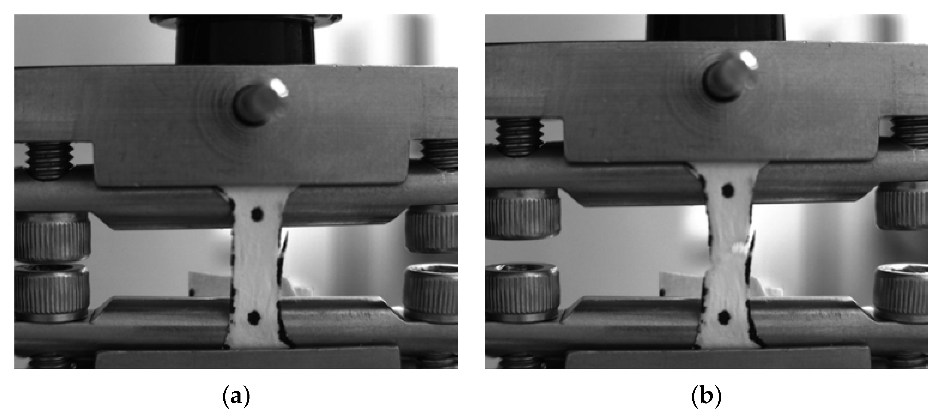
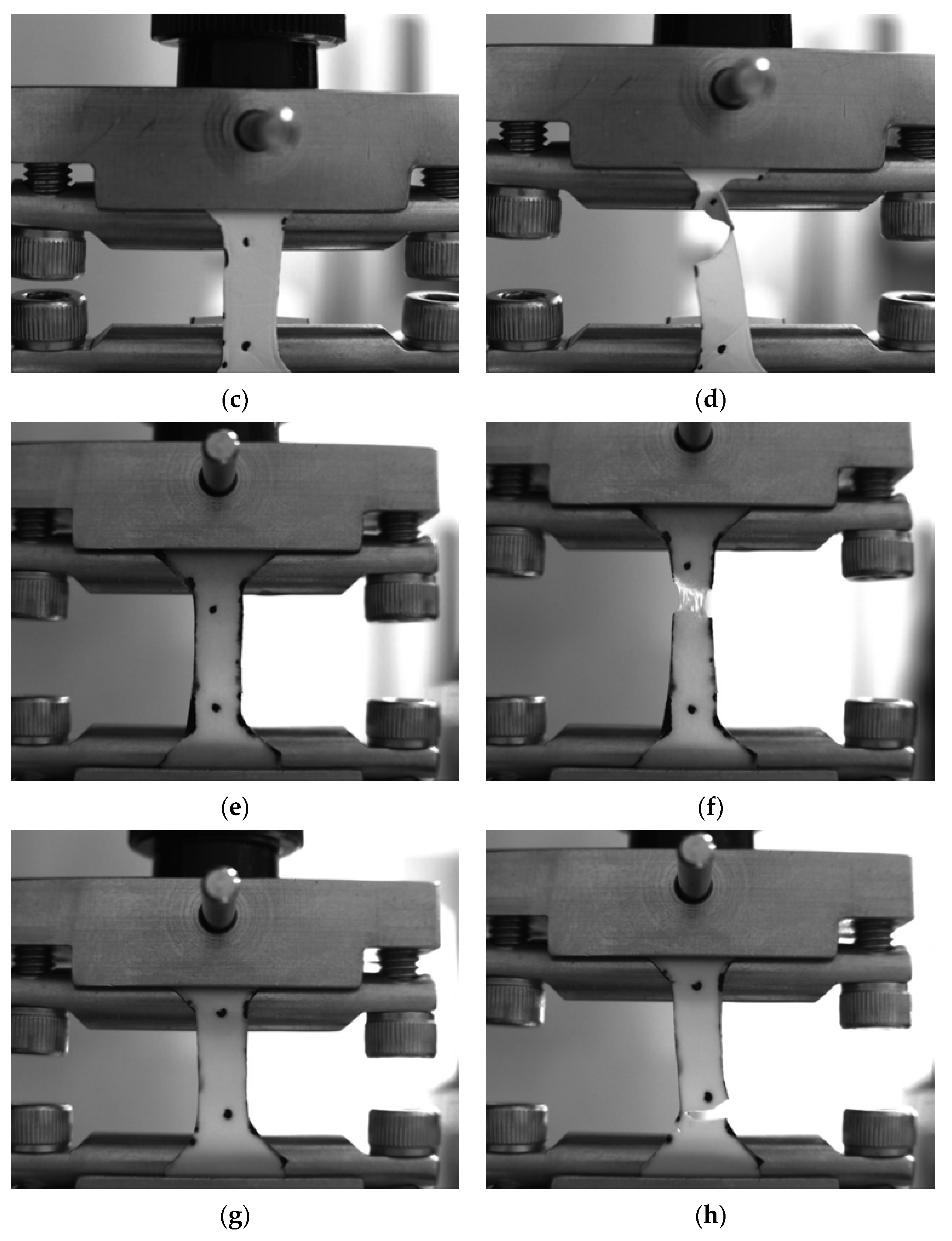
| Sample | EA-SBS | ES | ||
|---|---|---|---|---|
| Dry | Wet | Dry | Wet | |
| Elastic modulus, MPa | 25 ± 4 | 17 ± 3 | 72 ± 9 | 54 ± 6 |
| Tensile strength, MPa | 1.15 ± 0.21 | 1.18 ± 0.03 | 3.9 ± 0.3 | 2.9 ± 0.1 |
| Elongation at break, % | 7.7 ± 0.3 | 18 ± 3 | 14 ± 4 | 16 ± 2 |
Publisher’s Note: MDPI stays neutral with regard to jurisdictional claims in published maps and institutional affiliations. |
© 2022 by the authors. Licensee MDPI, Basel, Switzerland. This article is an open access article distributed under the terms and conditions of the Creative Commons Attribution (CC BY) license (https://creativecommons.org/licenses/by/4.0/).
Share and Cite
Demina, T.S.; Bolbasov, E.N.; Peshkova, M.A.; Efremov, Y.M.; Bikmulina, P.Y.; Birdibekova, A.V.; Popyrina, T.N.; Kosheleva, N.V.; Tverdokhlebov, S.I.; Timashev, P.S.; et al. Electrospinning vs. Electro-Assisted Solution Blow Spinning for Fabrication of Fibrous Scaffolds for Tissue Engineering. Polymers 2022, 14, 5254. https://doi.org/10.3390/polym14235254
Demina TS, Bolbasov EN, Peshkova MA, Efremov YM, Bikmulina PY, Birdibekova AV, Popyrina TN, Kosheleva NV, Tverdokhlebov SI, Timashev PS, et al. Electrospinning vs. Electro-Assisted Solution Blow Spinning for Fabrication of Fibrous Scaffolds for Tissue Engineering. Polymers. 2022; 14(23):5254. https://doi.org/10.3390/polym14235254
Chicago/Turabian StyleDemina, Tatiana S., Evgeniy N. Bolbasov, Maria A. Peshkova, Yuri M. Efremov, Polina Y. Bikmulina, Aisylu V. Birdibekova, Tatiana N. Popyrina, Nastasia V. Kosheleva, Sergei I. Tverdokhlebov, Peter S. Timashev, and et al. 2022. "Electrospinning vs. Electro-Assisted Solution Blow Spinning for Fabrication of Fibrous Scaffolds for Tissue Engineering" Polymers 14, no. 23: 5254. https://doi.org/10.3390/polym14235254