
Failure Prediction in 3D Printed Kevlar/Glass Fiber-Reinforced Nylon Structures with a Hole and Different Fiber Orientations


Abstract
:1. Introduction
2. Experimental and Analytical Studies
2.1. Materials
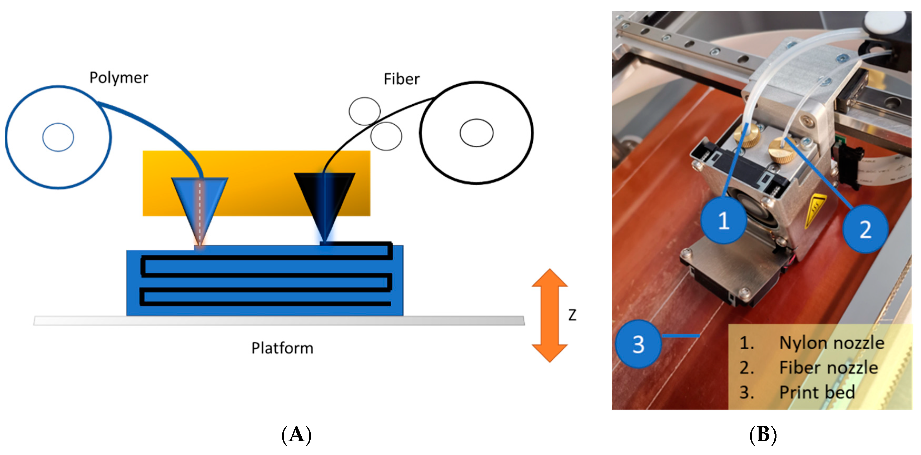
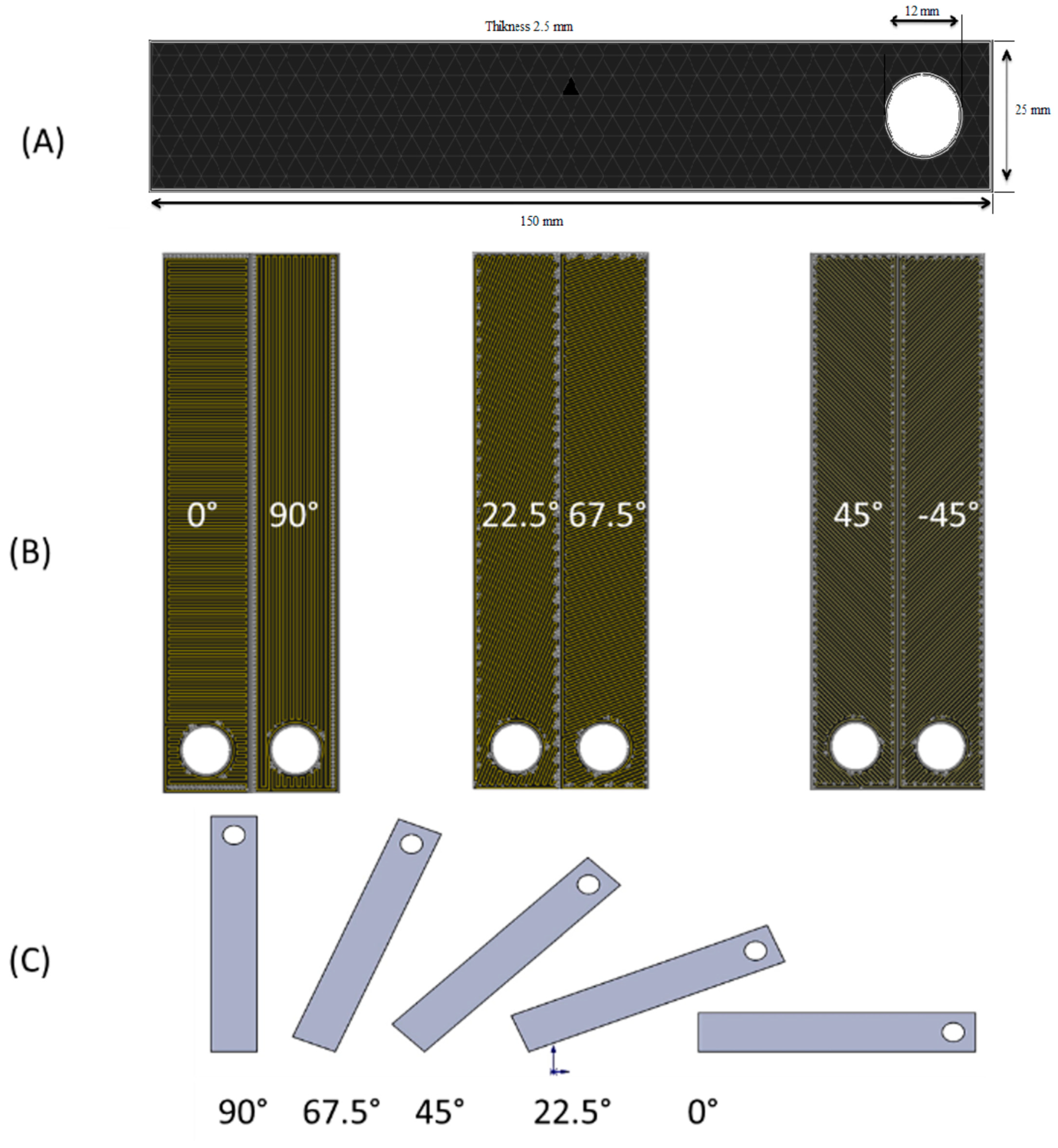
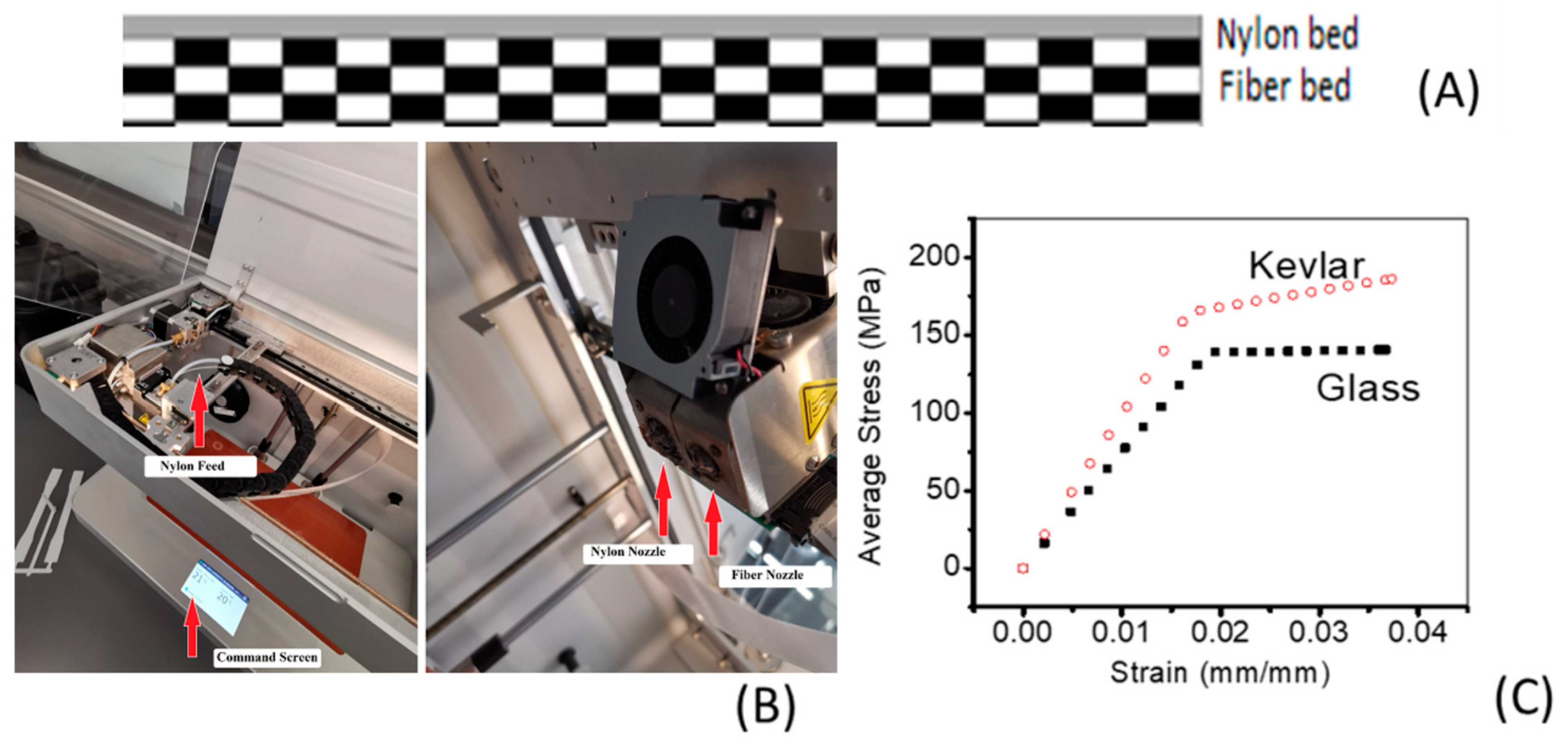
2.2. 3D Printing
2.3. Mechanical Properties
2.4. Analytical Studies
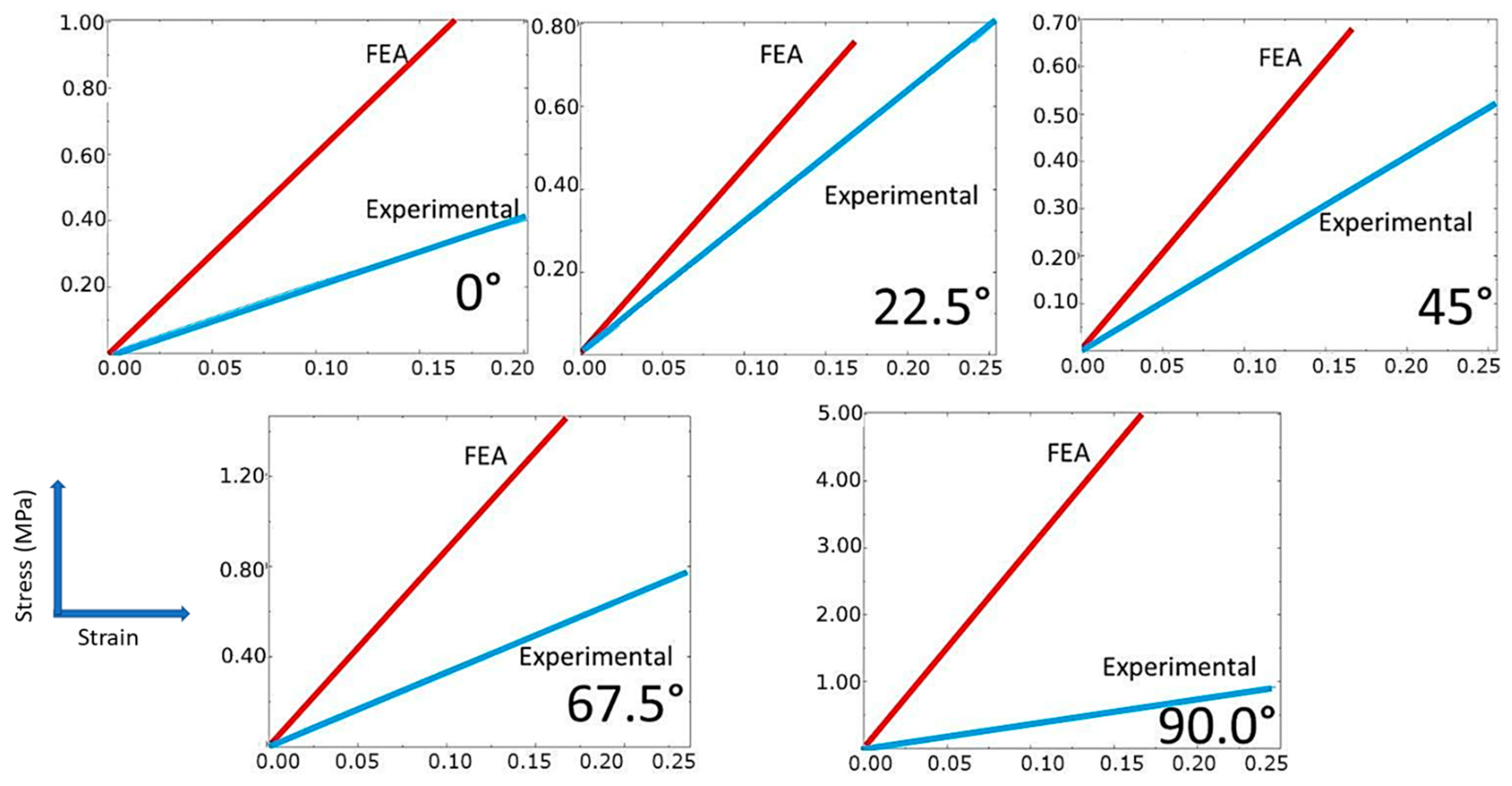
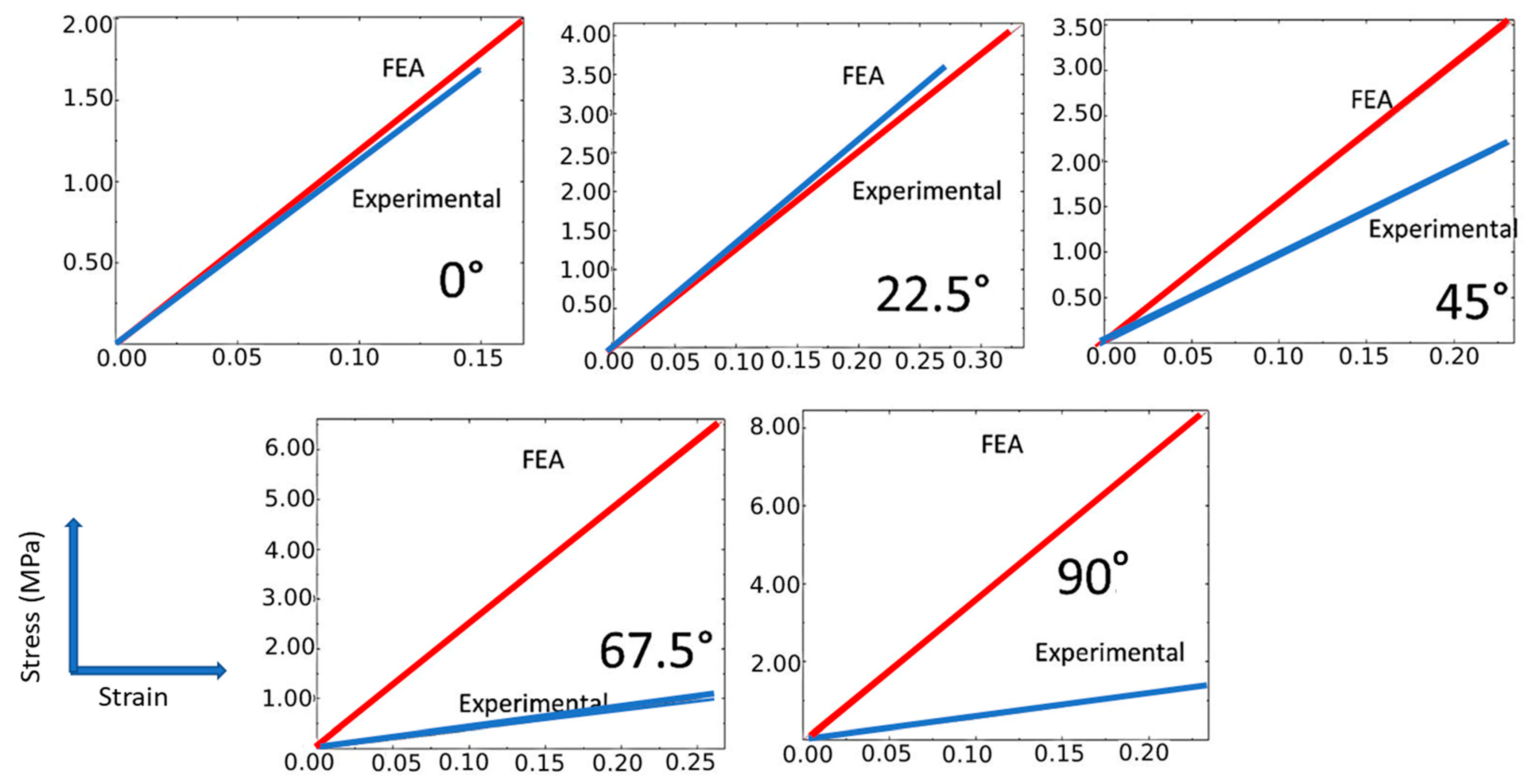
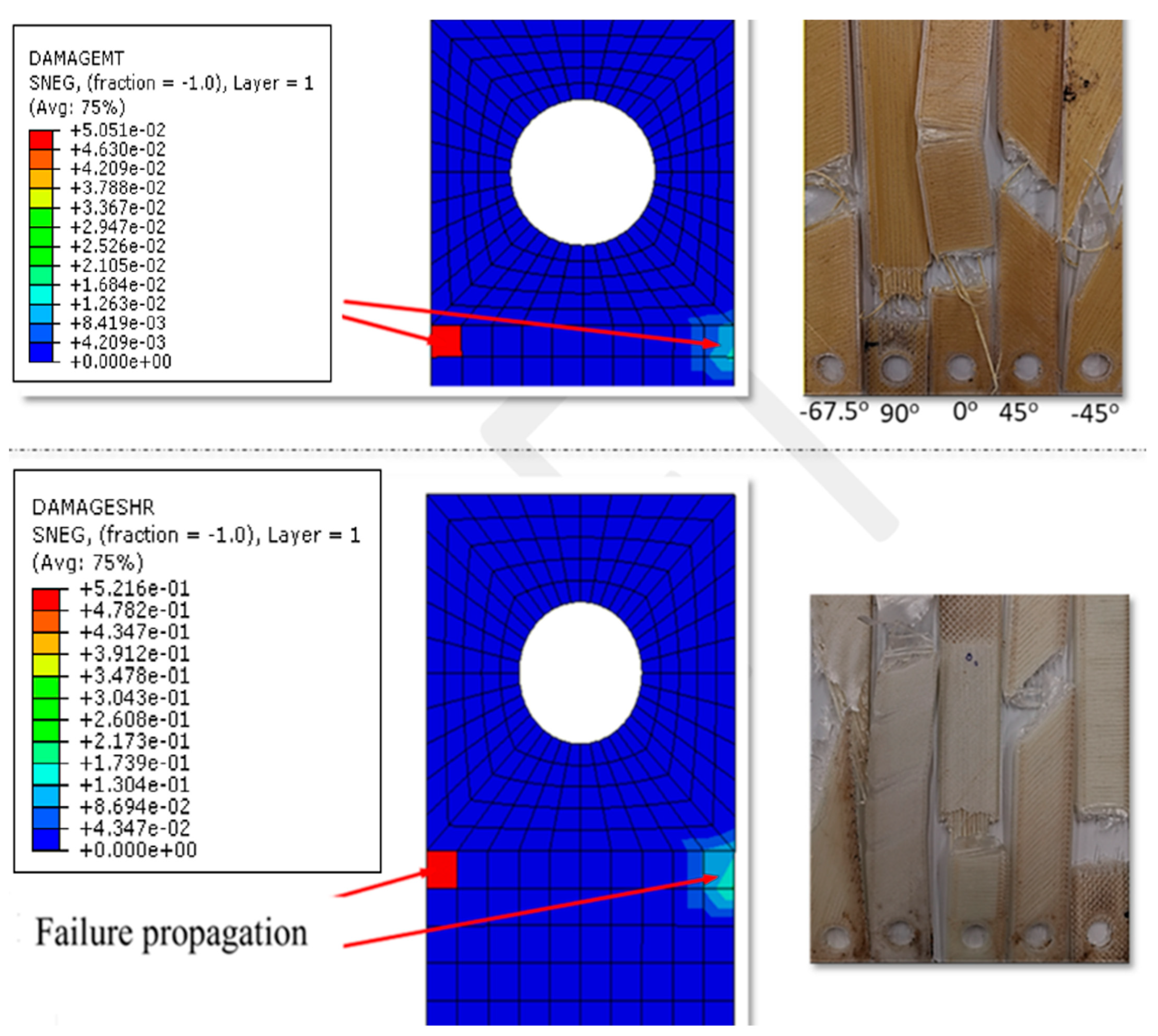
2.5. Finite Element Analysis
3. Results and Discussion
4. Conclusions
Funding
Institutional Review Board Statement
Data Availability Statement
Acknowledgments
Conflicts of Interest
References
- Daminabo, S.C.; Goel, S.; Grammatikos, S.A.; Nezhad, H.Y.; Thakur, V.K. Fused deposition modeling-based additive manufacturing (3D printing): Techniques for polymer material systems. Mater. Today Chem. 2020, 16, 100248. [Google Scholar] [CrossRef]
- Singh, S.; Singh, G.; Prakash, C.; Ramakrishna, S. Current status and future directions of fused filament fabrication. J. Manuf. Process. 2020, 55, 288–306. [Google Scholar] [CrossRef]
- Alfarisi, N.A.S.; Santos, G.N.C.; Norcahyo, R.; Sentanuhady, J.; Azizah, N.; Muflikhun, M.A. Model optimization and performance evaluation of hand cranked music box base structure manufactured via 3D printing. Heliyon 2021, 7, e08432. [Google Scholar] [CrossRef] [PubMed]
- Park, S.; Shou, W.; Makatura, L.; Matusik, W.; Fu, K. 3D printing of polymer composites: Materials, processes, and applications. Matter 2022, 5, 43–76. [Google Scholar] [CrossRef]
- Le Duigou, A.; Correa, D.; Ueda, M.; Matsuzaki, R.; Castro, M. A review of 3D and 4D printing of natural fibre biocomposites. Mater. Des. 2020, 194, 108911. [Google Scholar] [CrossRef]
- Falahati, M.; Ahmadvand, P.; Safaee, S.; Chang, Y.-C.; Lyu, Z.; Chen, R.; Li, L.; Lin, Y. Smart polymers and nanocomposites for 3D and 4D printing. Mater. Today 2020, 40, 215–245. [Google Scholar] [CrossRef]
- Blok, L.G.; Longana, M.L.; Yu, H.; Woods, B.K.S. An investigation into 3D printing of fibre reinforced thermoplastic composites. Addit. Manuf. 2018, 22, 176–186. [Google Scholar] [CrossRef]
- Chapiro, M. Current achievements and future outlook for composites in 3D printing. Reinf. Plast. 2016, 60, 372–375. [Google Scholar] [CrossRef]
- Mei, H.; Ali, Z.; Ali, I.; Cheng, L. Tailoring strength and modulus by 3D printing different continuous fibers and filled structures into composites. Adv. Compos. Hybrid Mater. 2019, 2, 312–319. [Google Scholar] [CrossRef]
- Wickramasinghe, S.; Do, T.; Tran, P. FDM-Based 3D Printing of Polymer and Associated Composite: A Review on Mechanical Properties, Defects and Treatments. Polymers 2020, 12, 1529. [Google Scholar] [CrossRef] [PubMed]
- Yuan, S.; Li, S.; Zhu, J.; Tang, Y. Additive manufacturing of polymeric composites from material processing to structural design. Compos. Part B Eng. 2021, 219, 108903. [Google Scholar] [CrossRef]
- Fu, X.; Zhang, X.; Huang, Z. Axial crushing of Nylon and Al/Nylon hybrid tubes by FDM 3D printing. Compos. Struct. 2021, 256, 113055. [Google Scholar] [CrossRef]
- Ramesh, M.; Panneerselvam, K. Mechanical investigation and optimization of parameter selection for Nylon material processed by FDM. Mater. Today Proc. 2021, 46, 9303–9307. [Google Scholar] [CrossRef]
- Aslanzadeh, S.; Saghlatoon, H.; Honari, M.M.; Mirzavand, R.; Montemagno, C.; Mousavi, P. Investigation on electrical and mechanical properties of 3D printed nylon 6 for RF/microwave electronics applications. Addit. Manuf. 2018, 21, 69–75. [Google Scholar] [CrossRef]
- Melenka, G.W.; Cheung, B.K.O.; Schofield, J.S.; Dawson, M.R.; Carey, J.P. Evaluation and prediction of the tensile properties of continuous fiber-reinforced 3D printed structures. Compos. Struct. 2016, 153, 866–875. [Google Scholar] [CrossRef]
- Heidari-Rarani, M.; Rafiee-Afarani, M.; Zahedi, A.M. Mechanical characterization of FDM 3D printing of continuous carbon fiber reinforced PLA composites. Compos. Part B Eng. 2019, 175, 107147. [Google Scholar] [CrossRef]
- Ghnatios, C.; Fayazbakhsh, K. Warping estimation of continuous fiber-reinforced composites made by robotic 3D printing. Addit. Manuf. 2022, 55, 102796. [Google Scholar] [CrossRef]
- Hatti, P.S.; Harisha, P.; Somanakatti, A.B.; Rakshith, M. Study on flexural behavior of glass-fiber reinforced polymer matrix composite. Mater. Today Proc. 2022, 54, 159–162. [Google Scholar] [CrossRef]
- Kalova, M.; Rusnakova, S.; Krzikalla, D.; Mesicek, J.; Tomasek, R.; Podeprelova, A.; Rosicky, J.; Pagac, M. 3D Printed Hollow Off-Axis Profiles Based on Carbon Fiber-Reinforced Polymers: Mechanical Testing and Finite Element Method Analysis. Polymers 2021, 13, 2949. [Google Scholar] [CrossRef] [PubMed]
- Calignano, F.; Lorusso, M.; Roppolo, I.; Minetola, P. Investigation of the Mechanical Properties of a Carbon Fibre-Reinforced Nylon Filament for 3D Printing. Machines 2020, 8, 52. [Google Scholar] [CrossRef]
- Al Abadi, H.; Thai, H.-T.; Paton-Cole, V.; Patel, V.I. Elastic properties of 3D printed fibre-reinforced structures. Compos. Struct. 2018, 193, 8–18. [Google Scholar] [CrossRef]
- Ahmad Sobri, S.; Whitehead, D.; Mohamed, M.; Mohamed, J.J.; Mohamad Amini, M.H.; Hermawan, A.; Mat Rasat, M.S.; Mohammad Sofi, A.Z.; Wan Ismail, W.O.; Norizan, M.N. Augmentation of the Delamination Factor in Drilling of Carbon Fibre-Reinforced Polymer Composites (CFRP). Polymers 2020, 12, 2461. [Google Scholar] [CrossRef] [PubMed]
- Rodriguez, J.F.; Thomas, J.P.; Renaud, J.E. Characterization of the mesostructure of fused-deposition acrylonitrile-butadiene-styrene materials. Rapid Prototyp. J. 2000, 6, 175–186. [Google Scholar] [CrossRef]
- Shi, K.; Yan, Y.; Mei, H.; Chen, C.; Cheng, L. 3D printing Kevlar fiber layer distributions and fiber orientations into nylon composites to achieve designable mechanical strength. Addit. Manuf. 2021, 39, 101882. [Google Scholar] [CrossRef]
- Dickson, A.N.; Barry, J.N.; McDonnell, K.A.; Dowling, D.P. Fabrication of continuous carbon, glass and Kevlar fibre reinforced polymer composites using additive manufacturing. Addit. Manuf. 2017, 16, 146–152. [Google Scholar] [CrossRef]
- Melton, G.H.; Peters, E.N.; Arisman, R.K. Engineering thermoplastics. In Applied Plastics Engineering Handbook; Elsevier: Amsterdam, The Netherlands, 2011; pp. 7–21. [Google Scholar]
- Bose, S.; Mahanwar, P.A. Effect of particle size of filler on properties of nylon-6. J. Miner. Mater. Charact. Eng. 2004, 3, 23–31. [Google Scholar]
- Yu, Z.; Ait-Kadi, A.; Brisson, J. Nylon/Kevlar composites. II: Investigation of interfaces. Polym. Eng. Sci. 1991, 31, 1228–1232. [Google Scholar] [CrossRef]
- Singh, T.J.; Samanta, S. Characterization of Kevlar Fiber and Its Composites: A Review. Mater. Today Proc. 2015, 2, 1381–1387. [Google Scholar] [CrossRef]
- Gupta, M.; Wang, K.K. Fiber orientation and mechanical properties of short-fiber-reinforced injection-molded composites: Simulated and experimental results. Polym. Compos. 1993, 14, 367–382. [Google Scholar]
- Hashimoto, M.; Okabe, T.; Sasayama, T.; Matsutani, H.; Nishikawa, M. Prediction of tensile strength of discontinuous carbon fiber/polypropylene composite with fiber orientation distribution. Compos. Part A Appl. Sci. Manuf. 2012, 43, 1791–1799. [Google Scholar] [CrossRef]
- Nak-Ho, S.; Suh, N.P. Effect of fiber orientation on friction and wear of fiber reinforced polymeric composites. Wear 1979, 53, 129–141. [Google Scholar] [CrossRef]
- Fu, S.-Y.; Lauke, B. Effects of fiber length and fiber orientation distributions on the tensile strength of short-fiber-reinforced polymers. Compos. Sci. Technol. 1996, 56, 1179–1190. [Google Scholar] [CrossRef]
- Landel, R.F.; Nielsen, L.E. Mechanical Properties of Polymers and Composites; CRC Press: Boca Raton, FL, USA, 1993. [Google Scholar]
- Chen, C.H.; Shun, C. Mechanical Properties of Fiber Reinforced Composites. J. Compos. Mater. 1967, 1, 30–41. [Google Scholar] [CrossRef]
- Muflikhun, M.A.; Sentanu, D.A. Characteristics and performance of carabiner remodeling using 3D printing with graded filler and different orientation methods. Eng. Fail. Anal. 2021, 130, 105795. [Google Scholar] [CrossRef]
- Rakesh, P.K.; Singh, I.; Kumar, D. Failure prediction in glass fiber reinforced plastics laminates with drilled hole under uni-axial loading. Mater. Des. 2010, 31, 3002–3007. [Google Scholar] [CrossRef]
- Bhattacharyya, D.; Horrigan, D.P.W. A study of hole drilling in Kevlar composites. Compos. Sci. Technol. 1998, 58, 267–283. [Google Scholar] [CrossRef]
- Loyola, B.R.; Briggs, T.M.; Arronche, L.; Loh, K.J.; La Saponara, V.; O′Bryan, G.; Skinner, J.L. Detection of spatially distributed damage in fiber-reinforced polymer composites. Struct. Health Monit. 2013, 12, 225–239. [Google Scholar] [CrossRef]
- Ahmad Sobri, S.; Heinemann, R.; Whitehead, D. Development of Laser Drilling Strategy for Thick Carbon Fibre Reinforced Polymer Composites (CFRP). Polymers 2020, 12, 2674. [Google Scholar] [CrossRef]
- Alharbi, M.; Kong, I.; Patel, V.I. Simulation of uniaxial stress–strain response of 3D-printed polylactic acid by nonlinear finite element analysis. Appl. Adhes. Sci. 2020, 8, 5. [Google Scholar] [CrossRef]
- Cersoli, T.; Yelamanchi, B.; MacDonald, E.; Carrillo, J.G.; Cortes, P. 3D printing of a continuous fiber-reinforced composite based on a coaxial Kevlar/PLA filament. Compos. Adv. Mater. 2021, 30, 26349833211000058. [Google Scholar] [CrossRef]
- Su, M.; Gu, A.; Liang, G.; Yuan, L. The effect of oxygen-plasma treatment on Kevlar fibers and the properties of Kevlar fibers/bismaleimide composites. Appl. Surf. Sci. 2011, 257, 3158–3167. [Google Scholar] [CrossRef]
- Nie, W.Z.; Li, J.; Zhou, Z. The ECP Grafting of Kevlar Fiber on Interfacial Adhesion of Polypropylene Composite. Polym.-Plast. Technol. Eng. 2010, 49, 305–308. [Google Scholar] [CrossRef]
- Touchard, F.; Chocinski-Arnault, L.; Fournier, T.; Magro, C.; Lafitte, A.; Caradec, A. Interfacial adhesion quality in 3D printed continuous CF/PA6 composites at filament/matrix and interlaminar scales. Compos. Part B Eng. 2021, 218, 108891. [Google Scholar] [CrossRef]


| Material Properties | Kevlar | Glass | Nylon |
|---|---|---|---|
| Longitudinal elastic modulus-E1 (MPa) | 29998 | 24998 | 378 |
| Transverse elastic modulus-E2 (MPa) | 9998 | 4998 | 378 |
| In-plane shear modulus-G12 and G23 (MPa) | 4998 | 998 | 142 |
| Poisson’s ratio- | 0.21 | 0.21 | 0.34 |
| Axial strength in tension- (MPa) | 598 | 558 | 54 |
| Axial strength in compression- (MPa) | 478 | 446 | 43 |
| Transverse strength in tension- (MPa) | 598 | 558 | 30 |
| Transverse strength in compression- (MPa) | 478 | 446 | 10.2 |
| Shear strength in tension- (MPa) | 38 | 38 | 7.2 |
| Shear strength in compression- (MPa) | 38 | 38 | 11 |
Publisher’s Note: MDPI stays neutral with regard to jurisdictional claims in published maps and institutional affiliations. |
© 2022 by the author. Licensee MDPI, Basel, Switzerland. This article is an open access article distributed under the terms and conditions of the Creative Commons Attribution (CC BY) license (https://creativecommons.org/licenses/by/4.0/).
Share and Cite
Albadrani, M.A. Failure Prediction in 3D Printed Kevlar/Glass Fiber-Reinforced Nylon Structures with a Hole and Different Fiber Orientations. Polymers 2022, 14, 4464. https://doi.org/10.3390/polym14204464
Albadrani MA. Failure Prediction in 3D Printed Kevlar/Glass Fiber-Reinforced Nylon Structures with a Hole and Different Fiber Orientations. Polymers. 2022; 14(20):4464. https://doi.org/10.3390/polym14204464
Chicago/Turabian StyleAlbadrani, Mohammed Aqeel. 2022. "Failure Prediction in 3D Printed Kevlar/Glass Fiber-Reinforced Nylon Structures with a Hole and Different Fiber Orientations" Polymers 14, no. 20: 4464. https://doi.org/10.3390/polym14204464