
Effects of Electrospinning Parameter Adjustment on the Mechanical Behavior of Poly-ε-caprolactone Vascular Scaffolds

 ,
,
Abstract
:1. Introduction
2. Materials and Methods
2.1. Rat Aorta Collection
2.2. Polymer Composition
2.3. Vascular Scaffold Fabrication
2.4. Scanning Electronic Microscopy (SEM)
2.5. Mechanical Properties Evaluation
2.6. Statistical Analysis
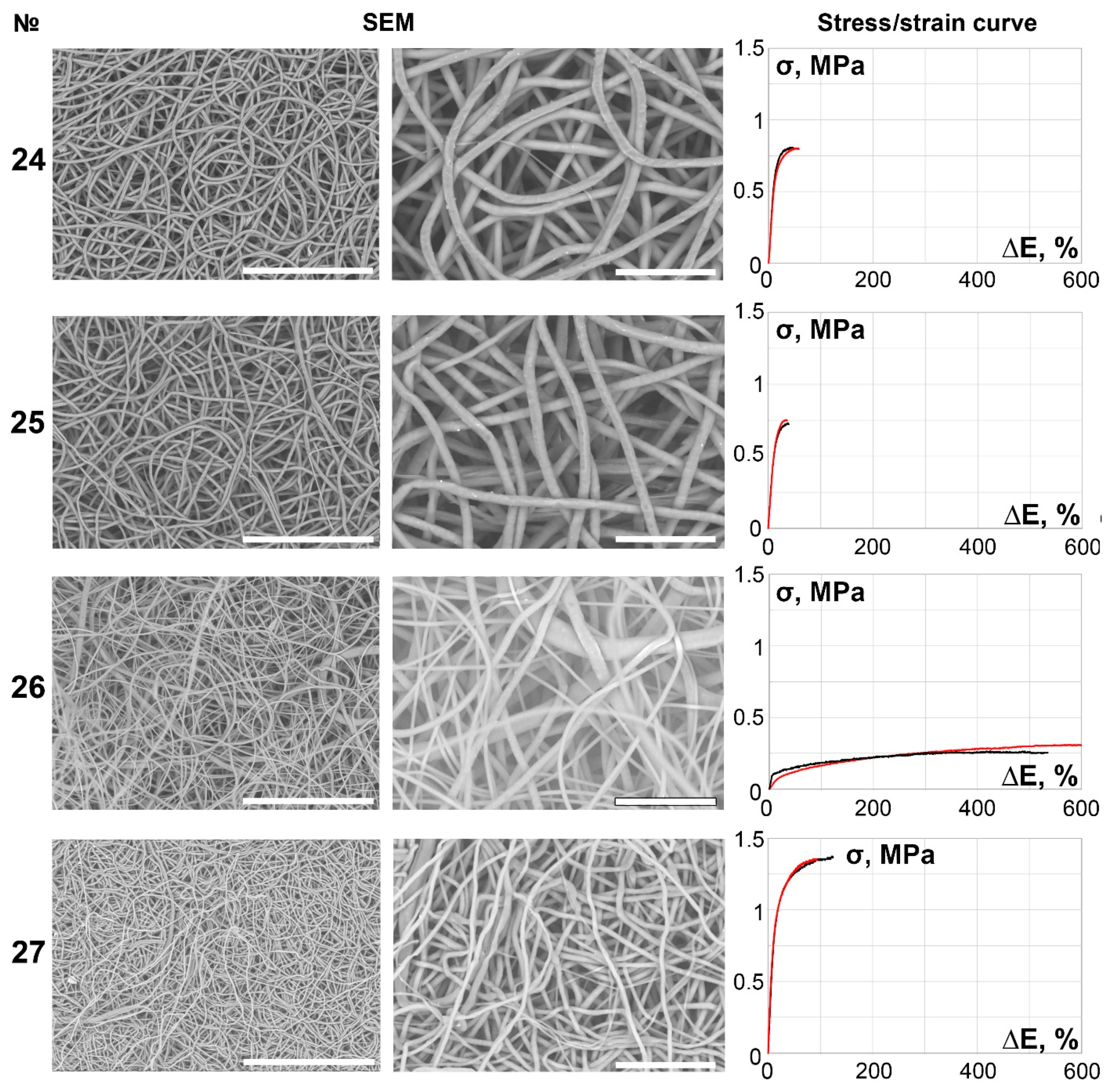
3. Results
4. Discussion
5. Conclusions
Author Contributions
Funding
Institutional Review Board Statement
Informed Consent Statement
Data Availability Statement
Acknowledgments
Conflicts of Interest
References
- Supaphol, P.; Suwantong, O.; Sangsanoh, P.; Srinivasan, S.; Jayakumar, R.; Nair, S.V. Electrospinning of Biocompatible Polymers and Their Potentials in Biomedical Applications. Biomed. Appl. Polym. Nanofibers 2011, 246, 213–239. [Google Scholar] [CrossRef]
- Pilehvar-Soltanahmadi, Y.; Akbarzadeh, A.; Moazzez-Lalaklo, N.; Zarghami, N. An update on clinical applications of electrospun nanofibers for skin bioengineering. Artif. Cells Nanomed. Biotechnol. 2016, 44, 1350–1364. [Google Scholar] [CrossRef]
- Pham, Q.P.; Sharma, U.; Mikos, A.G. Electrospinning of Polymeric Nanofibers for Tissue Engineering Applications: A Review. Tissue Eng. 2006, 12, 1197–1211. [Google Scholar] [CrossRef] [Green Version]
- Pelipenko, J.; Kocbek, P.; Kristl, J. Nanofiber diameter as a critical parameter affecting skin cell response. Eur. J. Pharm. Sci. 2015, 66, 29–35. [Google Scholar] [CrossRef] [PubMed]
- Kai, D.; Liow, S.S.; Loh, X.J. Biodegradable polymers for electrospinning: Towards biomedical applications. Mater. Sci. Eng. C 2014, 45, 659–670. [Google Scholar] [CrossRef] [PubMed]
- Zheng, J.; He, A.; Li, J.; Xu, J.; Han, C.C. Studies on the controlled morphology and wettability of polystyrene surfaces by electrospinning or electrospraying. Polymer 2006, 47, 7095–7102. [Google Scholar] [CrossRef]
- Ki, C.S.; Baek, D.H.; Gang, K.D.; Lee, K.H.; Um, I.C.; Park, Y.H. Characterization of gelatin nanofiber prepared from gelatin–formic acid solution. Polymer 2005, 46, 5094–5102. [Google Scholar] [CrossRef]
- Ojha, S.S.; Afshari, M.; Kotek, R.; Gorga, R.E. Morphology of electrospun nylon-6 nanofibers as a function of molecular weight and processing parameters. J. Appl. Polym. Sci. 2008, 108, 308–319. [Google Scholar] [CrossRef]
- Shenoy, S.L.; Bates, W.D.; Frisch, H.L.; Wnek, G.E. Role of chain entanglements on fiber formation during electrospinning of polymer solutions: Good solvent, non-specific polymer–polymer interaction limit. Polymer 2005, 46, 3372–3384. [Google Scholar] [CrossRef]
- Park, W.H.; Jeong, L.; Yoo, D.I.; Hudson, S. Effect of chitosan on morphology and conformation of electrospun silk fibroin nanofibers. Polymer 2004, 45, 7151–7157. [Google Scholar] [CrossRef]
- Meli, L.; Miao, J.; Dordick, J.S.; Linhardt, R.J. Electrospinning from room temperature ionic liquids for biopolymer fiber formation. Green Chem. 2010, 12, 1883–1892. [Google Scholar] [CrossRef]
- Zhang, C.; Yuan, X.; Wu, L.; Han, Y.; Sheng, J. Study on morphology of electrospun poly(vinyl alcohol) mats. Eur. Polym. J. 2005, 41, 423–432. [Google Scholar] [CrossRef]
- Cramariuc, B.; Cramariuc, R.; Scarlet, R.; Manea, L.R.; Lupu, I.G.; Cramariuc, O. Fiber diameter in electrospinning process. J. Electrost. 2013, 71, 189–198. [Google Scholar] [CrossRef]
- Demir, M.M.; Yilgor, I.; Yilgor, E.; Erman, B. Electrospinning of polyurethane fibers. Polymer 2002, 43, 3303–3309. [Google Scholar] [CrossRef]
- Yördem, O.S.; Papila, M.; Menceloğlu, Y.Z. Effects of electrospinning parameters on polyacrylonitrile nanofiber diameter: An investigation by response surface methodology. Mater. Des. 2008, 29, 34–44. [Google Scholar] [CrossRef] [Green Version]
- Megelski, S.; Stephens, J.S.; Chase, D.B.; Rabolt, J.F. Micro- and Nanostructured Surface Morphology on Electrospun Polymer Fibers. Macromolecules 2002, 35, 8456–8466. [Google Scholar] [CrossRef]
- Fallahi, D.; Rafizadeh, M.; Mohammadi, N.; Vahidi, B. Effect of applied voltage on jet electric current and flow rate in electrospinning of polyacrylonitrile solutions. Polym. Int. 2008, 57, 1363–1368. [Google Scholar] [CrossRef]
- Vaquette, C.; Cooper-White, J.J. Increasing electrospun scaffold pore size with tailored collectors for improved cell penetration. Acta Biomater. 2011, 7, 2544–2557. [Google Scholar] [CrossRef]
- Sattary, M.; Rafienia, M.; Khorasani, M.T.; Salehi, H. The effect of collector type on the physical, chemical, and biological properties of polycaprolactone/gelatin/nano-hydroxyapatite electrospun scaffold. J. Biomed. Mater. Res. Part B Appl. Biomater. 2019, 107, 933–950. [Google Scholar] [CrossRef] [PubMed]
- Doğan, Y.K.; Demirural, A.; Baykara, T. Single-needle electrospinning of PVA hollow nanofibers for core–shell structures. SN Appl. Sci. 2019, 1, 415. [Google Scholar] [CrossRef] [Green Version]
- Cohn, D.; Salomon, A.H. Designing biodegradable multiblock PCL/PLA thermoplastic elastomers. Biomaterials 2005, 26, 2297–2305. [Google Scholar] [CrossRef]
- Sinha, V.R.; Bansal, K.; Kaushik, R.; Kumria, R.; Trehan, A. Poly-ε-caprolactone microspheres and nanospheres: An overview. Int. J. Pharm. 2004, 278, 1–23. [Google Scholar] [CrossRef]
- Serrano, M.C.; Pagani, R.; Vallet-Regí, M.; Peña, J.; Rámila, A.; Izquierdo, I.; Portolés, M.T. In vitro biocompatibility assessment of poly(ε-caprolactone) films using L929 mouse fibroblasts. Biomaterials 2004, 25, 5603–5611. [Google Scholar] [CrossRef]
- Zhang, X.; Peng, X.; Zhang, S.W. Synthetic biodegradable medical polymers: Polymer blends. In Science and Principles of Biodegradable and Bioresorbable Medical Polymers; Zhang, X., Ed.; Woodhead Publishing: Cambridge, UK, 2017; pp. 217–254. [Google Scholar] [CrossRef]
- Bouchet, M.; Gauthier, M.; Maire, M.; Ajji, A.; Lerouge, S. Towards compliant small-diameter vascular grafts: Predictive analytical model and experiments. Mater. Sci. Eng. C 2019, 100, 715–723. [Google Scholar] [CrossRef]
- Wise, S.G.; Byrom, M.J.; Waterhouse, A.; Bannon, P.G.; Ng, M.K.C.; Weiss, A.S. A multilayered synthetic human elastin/polycaprolactone hybrid vascular graft with tailored mechanical properties. Acta Biomater. 2011, 7, 295–303. [Google Scholar] [CrossRef] [PubMed]
- Tokiwa, Y.; Calabia, B.P. Biodegradability and Biodegradation of Polyesters. J. Polym. Environ. 2007, 15, 259–267. [Google Scholar] [CrossRef]
- Wu, W.; Allen, R.A.; Wang, Y. Fast-degrading elastomer enables rapid remodeling of a cell-free synthetic graft into a neoartery. Nat. Med. 2012, 18, 1148–1153. [Google Scholar] [CrossRef] [Green Version]
- Leroux, A.; Egles, C.; Migonney, V. Impact of chemical and physical treatments on the mechanical properties of poly(ε-caprolactone) fibers bundles for the anterior cruciate ligament reconstruction. PLoS ONE 2018, 13, e0205722. [Google Scholar] [CrossRef] [PubMed]
- Croisier, F.; Duwez, A.-S.; Jérôme, C.; Léonard, A.F.; van der Werf, K.O.; Dijkstra, P.J.; Bennink, M.L. Mechanical testing of electrospun PCL fibers. Acta Biomater. 2012, 8, 218–224. [Google Scholar] [CrossRef]
- Coverdale, B.D.; Gough, J.E.; Sampson, W.W.; Hoyland, J.A. Use of lecithin to control fiber morphology in electrospun poly (ε-caprolactone) scaffolds for improved tissue engineering applications. J. Biomed. Mater. Res. Part A 2017, 105, 2865–2874. [Google Scholar] [CrossRef] [PubMed]
- Lee, S.J.; Oh, S.H.; Liu, J.; Soker, S.; Atala, A.; Yoo, J.J. The use of thermal treatments to enhance the mechanical properties of electrospun poly(ε-caprolactone) scaffolds. Biomaterials 2008, 29, 1422–1430. [Google Scholar] [CrossRef]
- Jahangiri, A.; Adibkia, K. Applications of electrospinning/electrospraying in drug delivery. BioImpacts 2016, 6, 1–2. [Google Scholar] [CrossRef] [Green Version]
- Wong, D.; Resendiz, J.; Egberts, P.; Park, S.S. Electrospinning of composite microbeads for tribological improvements. J. Manuf. Process. 2018, 34, 264–273. [Google Scholar] [CrossRef]
- Borisova, I.; Stoilova, O.; Manolova, N.; Rashkov, I. Modulating the Mechanical Properties of Electrospun PHB/PCL Materials by Using Different Types of Collectors and Heat Sealing. Polymers 2020, 12, 693. [Google Scholar] [CrossRef] [Green Version]
- Matsuzaki, Y.; Iwaki, R.; Reinhardt, J.W.; Chang, Y.-C.; Miyamoto, S.; Kelly, J.; Zbinden, J.; Blum, K.; Mirhaidari, G.; Ulziibayar, A.; et al. The effect of pore diameter on neo-tissue formation in electrospun biodegradable tissue-engineered arterial grafts in a large animal model. Acta Biomater. 2020, 115, 176–184. [Google Scholar] [CrossRef] [PubMed]
- Eichhorn, S.J.; Sampson, W.W. Statistical geometry of pores and statistics of porous nanofibrous assemblies. J. R. Soc. Interface 2005, 2, 309–318. [Google Scholar] [CrossRef]
- Suwantong, O. Biomedical applications of electrospun polycaprolactone fiber mats. Polym. Adv. Technol. 2016, 27, 1264–1273. [Google Scholar] [CrossRef]
- O’Connor, R.A.; Cahill, P.A.; McGuinness, G.B. Effect of electrospinning parameters on the mechanical and morphological characteristics of small diameter PCL tissue engineered blood vessel scaffolds having distinct micro and nano fibre populations—A DOE approach. Polym. Test. 2021, 96, 107119. [Google Scholar] [CrossRef]
- VanBavel, E.; Siersma, P.; Spaan, J.A.E. Elasticity of passive blood vessels: A new concept. Am. J. Physiol. Circ. Physiol. 2003, 285, H1986–H2000. [Google Scholar] [CrossRef] [Green Version]
- Bank, A.J.; Wang, H.; Holte, J.E.; Mullen, K.; Shammas, R.; Kubo, S.H. Contribution of Collagen, Elastin, and Smooth Muscle to In Vivo Human Brachial Artery Wall Stress and Elastic Modulus. Circulation 1996, 94, 3263–3270. [Google Scholar] [CrossRef]
- Ballyk, P.D.; Walsh, C.; Butany, J.; Ojha, M. Compliance mismatch may promote graft–artery intimal hyperplasia by altering suture-line stresses. J. Biomech. 1997, 31, 229–237. [Google Scholar] [CrossRef]


| % | № | Needle | Applied Voltage, kV | Feed Rate, mL/h | Collector Speed, rpm | Spinneret Speed, rpm | Tip to Collector Distance, cm | Cleaning Interval, s | Solution Volume, mL |
|---|---|---|---|---|---|---|---|---|---|
| 5% | 1 | 22G | 16 | 0.5 | 300 | 100 | 15 | 30 | 0.5 |
| 2 | 16 | 0.5 | 300 | 150 | 15 | 30 | 1 | ||
| 3 | 16 | 0.5 | 250 | 150 | 15 | 30 | 1 | ||
| 4 | 27G | 16 | 0.5 | 300 | 150 | 15 | 20 | 1 | |
| 5 | 16 | 0.5 | 250 | 100 | 15 | 20 | 1 | ||
| 8% | 6 | 22G | 16 | 0.4 | 300 | 150 | 15 | 30 | 1 |
| 7 | 23 | 0.3 | 150 | 100 | 15 | 59 | 0.5 | ||
| 8 | 27G | 16 | 0.5 | 300 | 150 | 15 | 59 | 1 | |
| 9 | 16 | 0.5 | 250 | 100 | 15 | 59 | 1 | ||
| 10% | 10 | 22G | 16 | 0.5 | 300 | 100 | 15 | 59 | 0.5 |
| 11 | 16 | 0.5 | 300 | 100 | 14 | 59 | 0.5 | ||
| 12 | 23 | 0.3 | 150 | 100 | 15 | 30 | 0.5 | ||
| 13 | 27G | 16 | 0.5 | 300 | 100 | 15 | 59 | 1 | |
| 14 | 16 | 0.5 | 300 | 150 | 15 | 59 | 1 | ||
| 12% | 15 | 22G | 17 | 0.4 | 300 | 150 | 15 | 30 | 1 |
| 16 | 20 | 0.6 | 250 | 200 | 15 | 30 | 0.6 | ||
| 17 | 27G | 17 | 0.4 | 300 | 150 | 15 | 30 | 0.7 | |
| 18 | 16 | 0.4 | 250 | 150 | 15 | 30 | 0.6 | ||
| 19 | 15 | 0.4 | 250 | 100 | 15 | 30 | 0.5 | ||
| 14% | 20 | 22G | 20 | 0.6 | 250 | 200 | 15 | 30 | 1 |
| 21 | 18 | 0.4 | 300 | 150 | 15 | 30 | 0.5 | ||
| 22 | 23 | 0.3 | 150 | 100 | 15 | 30 | 0.3 | ||
| 23 | 27G | 20 | 0.3 | 300 | 150 | 15 | 30 | 0.4 | |
| 16% | 24 | 22G | 23 | 0.3 | 150 | 100 | 15 | 30 | 0.3 |
| 25 | 20 | 0.3 | 300 | 150 | 15 | 30 | 0.4 | ||
| 26 | 27G | 20 | 0.3 | 300 | 150 | 15 | 30 | 0.4 | |
| 27 | 20 | 0.3 | 250 | 100 | 15 | 20 | 0.5 |
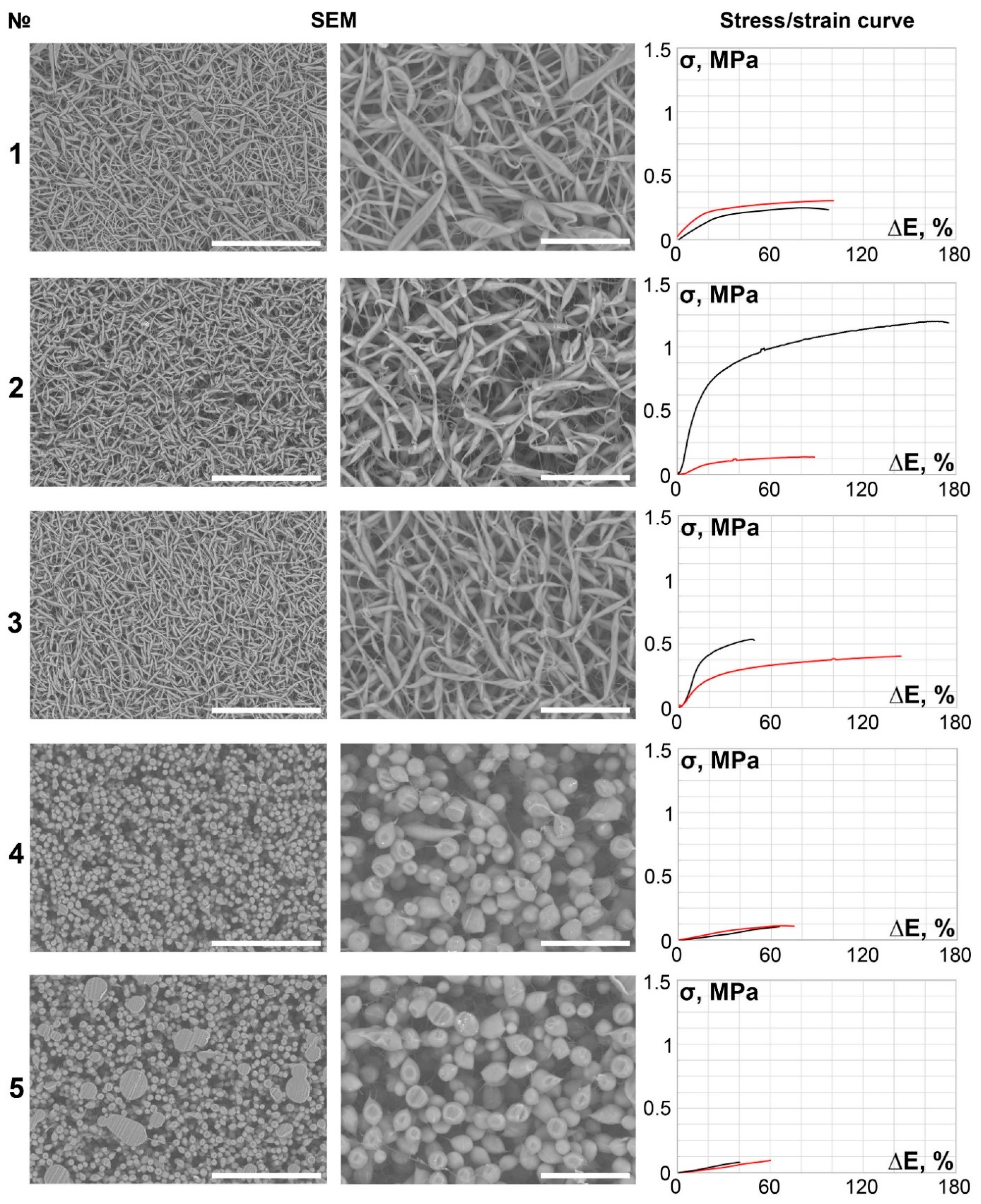
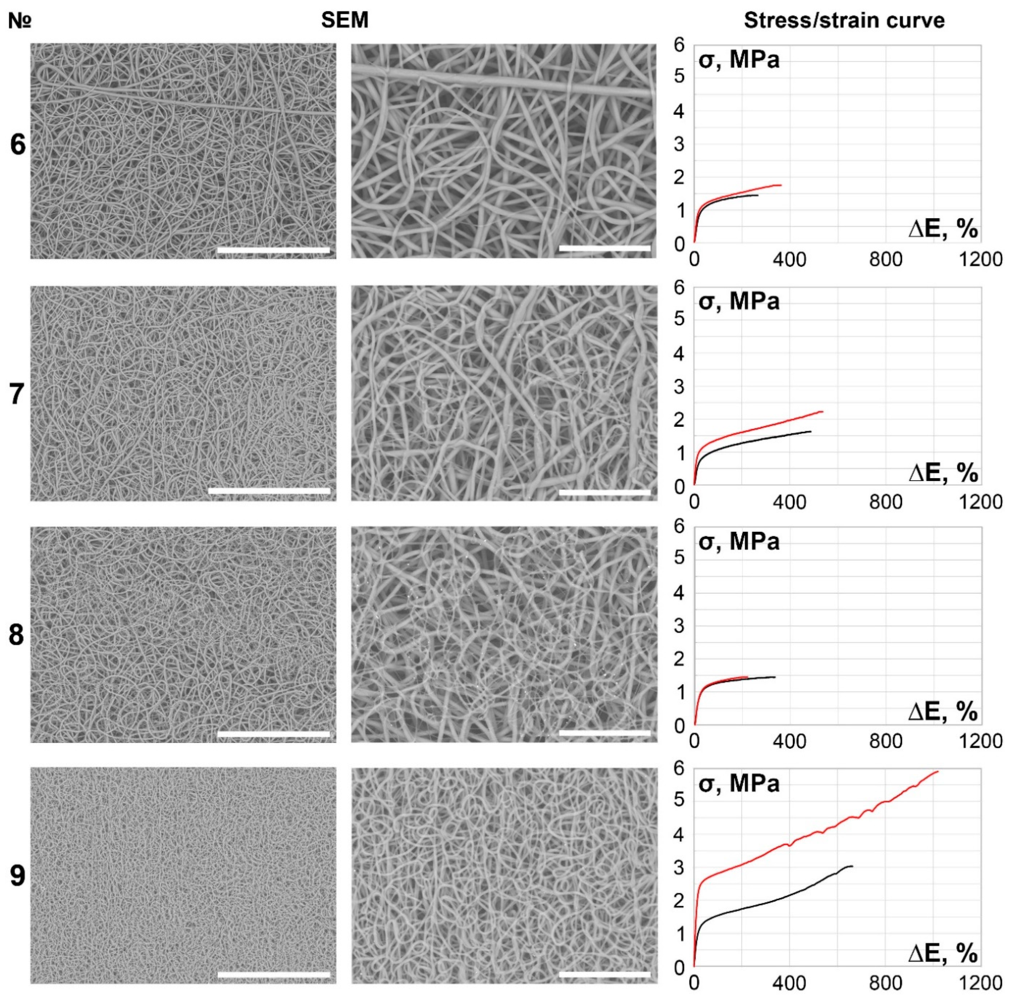
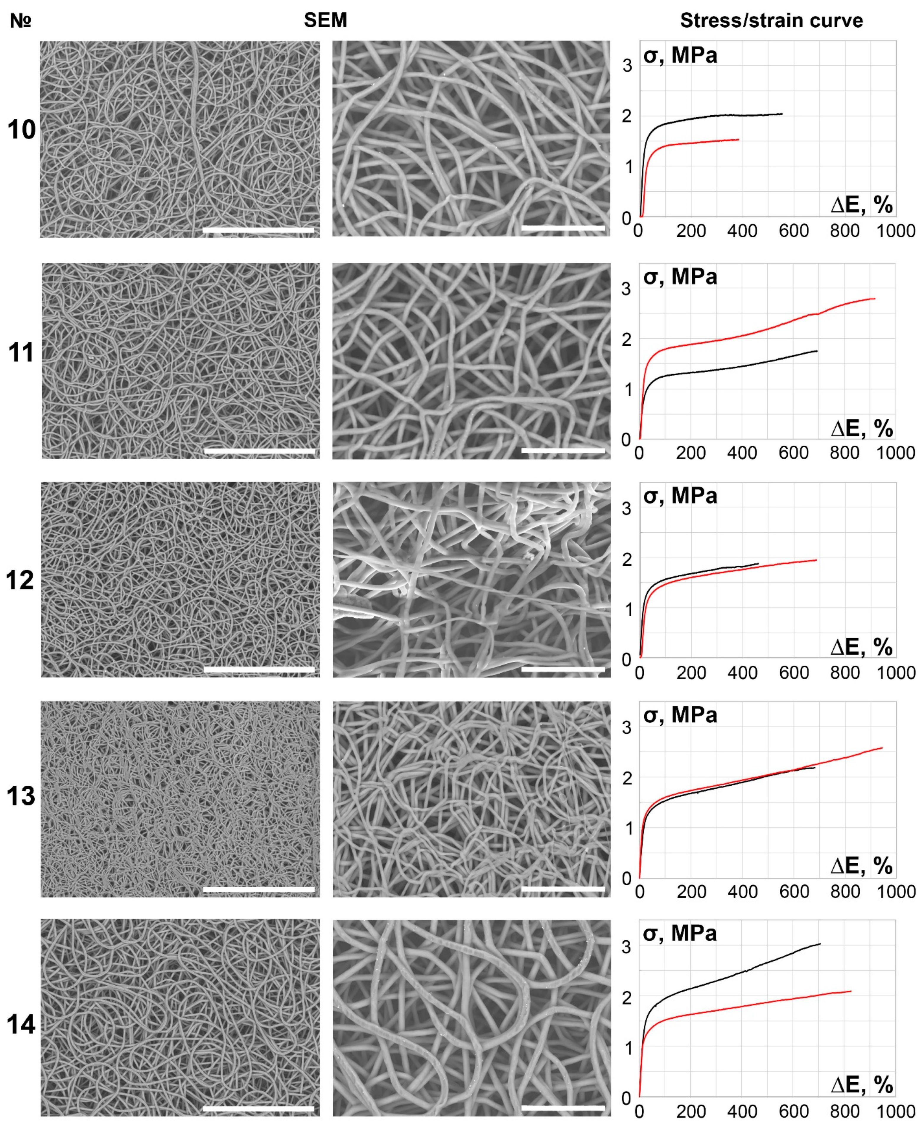
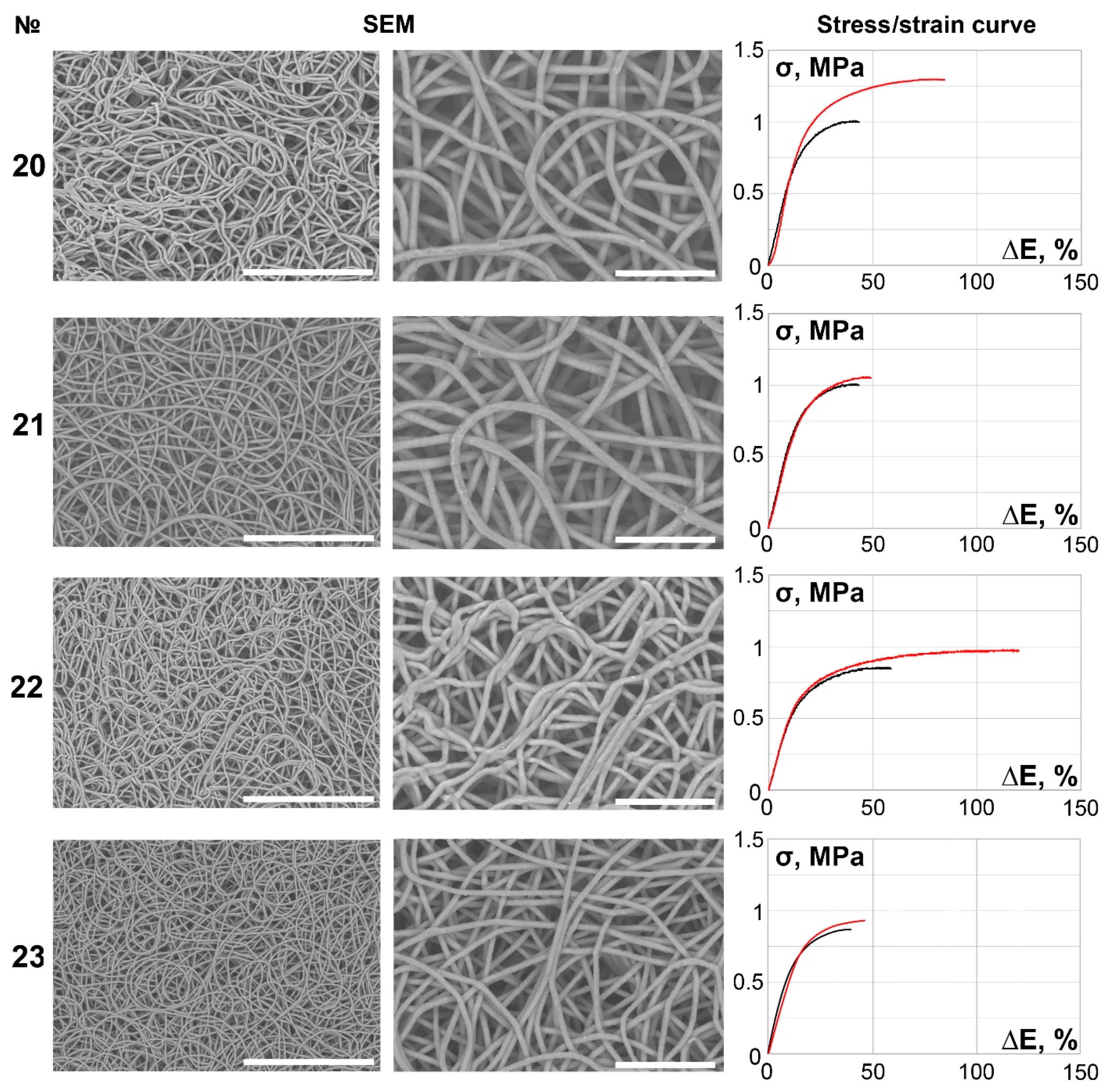
| Concentration by Mass, % | № | Fiber Diameter, µm | Pore Diameter, µm | Failure Strain, % | Failure Stress, MPa | E Mod, MPa | |||
|---|---|---|---|---|---|---|---|---|---|
| Axial | Circumferential | Axial | Circumferential | Axial | Circumferential | ||||
| 5 | 1 | 4.182 ± 0.72 | 11.34 ± 0.8 | 98.43 ± 11.03 | 95.48 ± 8.82 | 0.31 ± 0.03 | 0.31 ± 0.03 | 0.32 ± 0.02 | 0.32 ± 0.01 |
| 2 | 4.688 ± 0.25 | 14.85 ± 1.3 | 87.13 ± 9.12 | 174.26 ± 16.69 | 0.17 ± 0.02 | 1.21 ± 0.09 | 0.19 ± 0.01 | 0.69 ± 0.03 | |
| 3 | 4.4 ± 0.46 | 13.32 ± 1.15 | 47.65 ± 3.87 | 142.61 ± 12.07 | 0.54 ± 0.04 | 0.41 ± 0.03 | 1.13 ± 0.09 | 0.29 ± 0.01 | |
| 4 | 12.21 ± 0.46 | 16.9 ± 0.93 | 74.02 ± 5.43 | 94.40 ± 6.53 | 0.12 ± 0.01 | 0.19 ± 0.01 | 0.16 ± 0.01 | 0.30 ± 0.02 | |
| 5 | 12.46 ± 0.38 | 15.91 ± 1.37 | 59.45 ± 2.61 | 39.38 ± 1.38 | 0.17 ± 0.02 | 0.09 ± 0.01 | 0.28 ± 0.01 | 0.22 ± 0.01 | |
| 8 | 6 | 2.46 ± 0.24 | 14.48 ± 0.79 | 362.20 ± 31.25 | 264.96 ± 19.62 | 1.75 ± 0.09 | 1.44 ± 0.07 | 0.48 ± 0.03 | 0.54 ± 0.05 |
| 7 | 3.02 ± 0.51 | 10.08 ± 0.56 | 536.42 ± 35.93 | 486.60 ± 27.95 | 2.22 ± 0.17 | 1.62 ± 0.11 | 0.41 ± 0.04 | 0.33 ± 0.01 | |
| 8 | 2.15 ± 0.14 | 8.49 ± 0.48 | 219.45 ± 20.86 | 334.91 ± 22.7 | 1.46 ± 0.11 | 1.45 ± 0.08 | 0.66 ± 0.03 | 0.43 ± 0.04 | |
| 9 | 1.4 ± 0.03 | 6.99 ± 0.31 | 1019.15 ± 79.01 | 661.82 ± 53.98 | 5.46 ± 0.38 | 3.03 ± 0.23 | 0.54 ± 0.05 | 0.46 ± 0.05 | |
| 10 | 10 | 3.32 ± 0.27 | 7.78 ± 0.93 | 378.75 ± 17.18 | 553.01 ± 37.34 | 1.53 ± 0.16 | 2.05 ± 0.18 | 0.40 ± 0.02 | 0.37 ± 0.02 |
| 11 | 3.34 ± 0.18 | 5.87 ± 0.75 | 917.42 ± 51.95 | 692.0 ± 64.82 | 2.79 ± 0.21 | 1.76 ± 0.12 | 0.30 ± 0.01 | 0.25 ± 0.01 | |
| 12 | 2.74 ± 0.13 | 11.26 ± 0.8 | 668.14 ± 22.78 | 459.62 ± 39.76 | 1.95 ± 0.2 | 1.88 ± 0.1 | 0.28 ± 0.01 | 0.41 ± 0.03 | |
| 13 | 2.15 ± 0.13 | 14.75 ± 1.01 | 943.76 ± 66.23 | 681.75 ± 59.21 | 2.58 ± 0.16 | 2.19 ± 0.16 | 0.27 ± 0.01 | 0.32 ± 0.03 | |
| 14 | 4.75 ± 0.15 | 36.5 ± 1.85 | 825.93 ± 72.97 | 705.90 ± 62. 19 | 2.09 ± 0.13 | 3.03 ± 0.25 | 0.25 ± 0.01 | 0.43 ± 0.03 | |
| 12 | 15 | 7.8 ± 1.07 | 42.29 ± 2.31 | 45.38 ± 3.33 | 32.93 ± 1.12 | 0.93 ± 0.01 | 1.12 ± 0.09 | 2.06 ± 0.16 | 3.41 ± 0.27 |
| 16 | 5.4 ± 0.17 | 39.42 ± 1.6 | 106.85 ± 9.32 | 64.04 ± 4.09 | 1.35 ± 0.14 | 1.09 ± 0.09 | 1.26 ± 0.02 | 1.70 ± 0.09 | |
| 17 | 1.93 ± 0.3 | 13.06 ± 1.6 | 800.68 ± 68.04 | 636.37 ± 60.14 | 2.74 ± 0.24 | 2.28 ± 0.15 | 0.34 ± 0.01 | 0.36 ± 0.01 | |
| 18 | 2.5 ± 0.25 | 24.76 ± 6.69 | 182.97 ± 5.25 | 350.57 ± 27.83 | 1.46 ± 0.09 | 2.30 ± 0.13 | 0.80 ± 0.05 | 0.66 ± 0.05 | |
| 19 | 3.11 ± 0.09 | 39.42 ± 0.84 | 92.58 ± 7.54 | 155.89 ± 13.61 | 1.68 ± 0.15 | 1.35 ± 0.06 | 1.82 ± 0.09 | 0.87 ± 0.07 | |
| 14 | 20 | 4.29 ± 0.2 | 22.61 ± 1.95 | 83.40 ± 7.36 | 90.67 ± 7.32 | 1.30 ± 0.11 | 1.24 ± 0.11 | 1.55 ± 0.12 | 1.37 ± 0.13 |
| 21 | 4.82 ± 0.14 | 19.58 ± 1.47 | 48.54 ± 2.98 | 42.40 ± 1.78 | 1.06 ± 0.09 | 1.01 ± 0.09 | 2.18 ± 0.11 | 2.38 ± 0.18 | |
| 22 | 5.29 ± 0.29 | 25.22 ± 1.82 | 119.49 ± 11.01 | 58.15 ± 4.22 | 0.98 ± 0.01 | 0.85 ± 0.05 | 0.82 ± 0.04 | 1.47 ± 0.12 | |
| 23 | 3.07 ± 0.05 | 14.45 ± 0.68 | 45.71 ± 3.46 | 38.96 ± 2.52 | 0.94 ± 0.06 | 0.86 ± 0.04 | 2.06 ± 0.02 | 2.26 ± 0.1 | |
| 16 | 24 | 4.85 ± 0.28 | 41.5 ± 4.04 | 57.23 ± 4.17 | 46.60 ± 3.07 | 0.80 ± 0.03 | 0.81 ± 0.07 | 1.40 ± 0.08 | 1.73 ± 0.16 |
| 25 | 4.21 ± 0.53 | 45.53 ± 4.06 | 35.34 ± 2.82 | 38.32 ± 2.05 | 0.75 ± 0.04 | 0.73 ± 0.03 | 2.13 ± 0.09 | 1.90 ± 0.13 | |
| 26 | 4.01 ± 0.69 | 31.78 ± 2.18 | 616.0 ± 35.1 | 534.87 ± 41.44 | 0.31 ± 0.01 | 0.26 ± 0.01 | 0.05 ± 0.01 | 0.05 ± 0.01 | |
| 27 | 2.91 ± 0.36 | 20.8 ± 1.4 | 92.80 ± 8.75 | 123.40 ± 10.06 | 1.35 ± 0.07 | 1.37 ± 0.11 | 1.46 ± 0.09 | 1.11 ± 0.1 | |
| Rat Aorta | 91.13 ± 8.91 | 215.0 ± 18.9 | 5.45 ± 1.72 | 2.01 ± 0.17 | 5.98 ± 0.39 | 0.94 ± 0.08 | |||
Publisher’s Note: MDPI stays neutral with regard to jurisdictional claims in published maps and institutional affiliations. |
© 2022 by the authors. Licensee MDPI, Basel, Switzerland. This article is an open access article distributed under the terms and conditions of the Creative Commons Attribution (CC BY) license (https://creativecommons.org/licenses/by/4.0/).
Share and Cite
Dokuchaeva, A.A.; Timchenko, T.P.; Karpova, E.V.; Vladimirov, S.V.; Soynov, I.A.; Zhuravleva, I.Y. Effects of Electrospinning Parameter Adjustment on the Mechanical Behavior of Poly-ε-caprolactone Vascular Scaffolds. Polymers 2022, 14, 349. https://doi.org/10.3390/polym14020349
Dokuchaeva AA, Timchenko TP, Karpova EV, Vladimirov SV, Soynov IA, Zhuravleva IY. Effects of Electrospinning Parameter Adjustment on the Mechanical Behavior of Poly-ε-caprolactone Vascular Scaffolds. Polymers. 2022; 14(2):349. https://doi.org/10.3390/polym14020349
Chicago/Turabian StyleDokuchaeva, Anna A., Tatyana P. Timchenko, Elena V. Karpova, Sergei V. Vladimirov, Ilya A. Soynov, and Irina Y. Zhuravleva. 2022. "Effects of Electrospinning Parameter Adjustment on the Mechanical Behavior of Poly-ε-caprolactone Vascular Scaffolds" Polymers 14, no. 2: 349. https://doi.org/10.3390/polym14020349