1. Introduction
Reinforced concrete ribbed girder bridge deck slabs are subjected to material deterioration and fatigue under the repeated activity of large vehicles. The load and fatigue resistance of the bridge deck slabs gradually decrease. To resolve the low performance problems caused by material deterioration and fatigue of reinforced concrete ribbed girder bridge deck slabs, reasonable and effective strengthening of bridge deck slabs has gradually attracted the attention of scientists and technicians. Rahman et al. [
1] selected a CFRP grid for the reinforcement of bridge deck slabs and carried out fatigue performance tests in the laboratory. Kongguo et al. [
2] selected CFRP sheets for strengthening the deck slab of a solid bridge and analyzed the strengthening effect. Christina et al. [
3] carried out comparative tests by selecting different types of mounted bars for bridge deck slabs. Yi et al. [
4] analyzed the maintenance and reinforcement technology of a highway bridge deck and reinforcement layer. Li [
5] selected FRP for reinforcing reinforced concrete one-way slabs and carried out bending tests. Biliang [
6] selected CFRP for strengthening the bridge deck slab and carried out ductility tests. Chanhao [
7] selected CFRP sheets for the reinforcement of bridge deck slabs and evaluated the fatigue resistance. Fang [
8] selected BFRP grids for strengthening the bridge deck slab and carried out bending tests, while Yu et al. [
9] selected FRP bars reinforcement for bridge deck slabs and carried out bending tests.
Damaged concrete bridge deck slabs can be reinforced with various materials used for damage patching, primarily steel plates and composite fiber-reinforced materials [
10,
11]. The reinforcement methods are mainly divided into three: external bonded reinforcement, external prestressing reinforcement, and near-surface mounted reinforcement. The external prestressing reinforcement involves using CFRP bars [
12] or steel bars [
13] for achieving reinforcement outside the structure. This method is difficult to implement and is limited by the space between the bridge deck slabs. The near-surface mounted reinforcement involves embedding the reinforcement materials into the original structure for reinforcement [
14]. This method damages the original structure when implemented. The comparison shows that the external bonded reinforcement is the most ideal. The application of steel plates in a concrete bridge deck slab reinforcement is somewhat limited because they are prone to corrosion and have poor durability [
15,
16,
17]. In contrast, composite fiber-reinforced materials are corrosion-resistant, have high specific strength, and are fatigue-resistant. Currently, many scholars are conducting research on external carbon-fiber-reinforced polymers (CFRP) reinforcement technology. Mhanna et al. [
18] conducted an experimental study on the shear load capacity of reinforced concrete beams strengthened with CFRP laminates. Al-Saawani et al. [
19] conducted an experimental study on FRP U-wrap anchorage. Al-Huthaifi et al. [
20] conducted an experimental study on reinforced concrete beams with longitudinal circular holes, using the CFRP strips strengthening method. Toutanji et al. [
21] conducted a fatigue test study on concrete beams reinforced with CFRP. Al-Ghrery et al. [
22] explored the effect of surface concavity of concrete structures on the performance of adhered CFRP reinforcement. Li [
23], Yang [
24], and Yang [
25] collated, summarized, and analyzed the reinforcement technology of FRP in concrete structures. Zhou [
26] concluded from an experimental study that the damage modes of CFRP-strengthened reinforced concrete beams under fatigue loading are mainly fatigue crushing of concrete in the compression zone, fatigue fracture of steel, and fatigue peeling at the interface. Research on U-shaped jacket [
27], anchorage [
28], and near-surface mounted reinforcement techniques [
29] has advanced and developed to address the fatigue peeling damage of CFRP. In addition, CFRP is used for non-conventional reinforcement, such as the use of CFRP ropes for reinforcing RC joints under seismic loading [
30]. CFRP reinforcement in concrete structures has been tried in various ways and the technology has matured. Jinping [
31] repaired and strengthened the deck slab of an existing bridge by increasing the deck slab thickness and the amount of reinforcing steel, which improved the bearing capacity of the deck slab. This reinforcement method increases the self-weight of the structure, but its cost is large. External CFRP reinforcement is non-destructive to the structure and has a low cost. Therefore, reinforcement methods such as external CFRP cloth and CFRP mesh have certain advantages for concrete bridge deck slab reinforcement.
The fatigue damage process of reinforced concrete ribbed girder bridge deck slabs is complex, making it difficult to determine a reasonable and effective reinforcement method to extend their service lives. At present, research on deck slab strengthening technology is far less than that on other components, such as beams and columns [
32], and studies on fatigue-strengthening technology of reinforced concrete ribbed girder bridge deck slabs are even fewer. Therefore, it is of practical significance to develop an external laminated steel plate and CFRP material to strengthen a bridge deck slab and study the changes in its fatigue life.
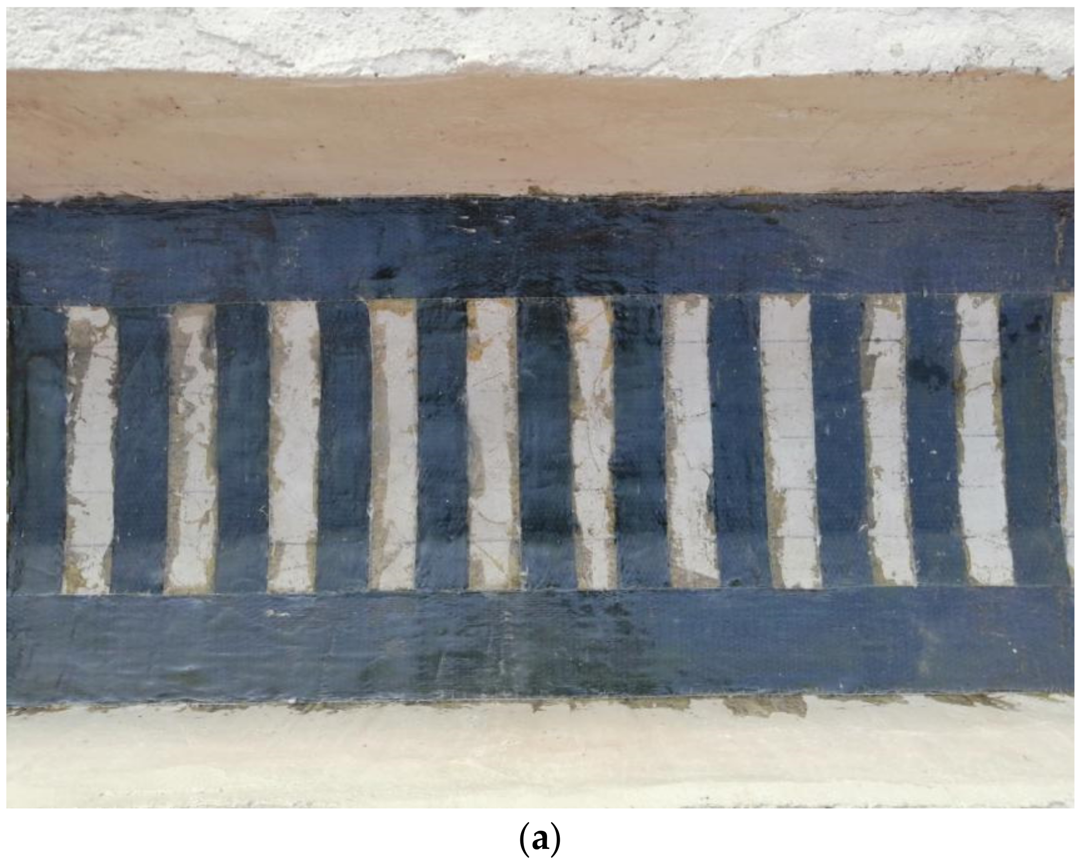
To facilitate inspection and maintenance, the external steel plate reinforcement can be cut into strips, pasted at a certain distance from the bottom of the plate, and anchored at the end [
33,
34,
35,
36]. Liqiang et al. [
37] conducted a fatigue test study on steel-UHPC bridge deck slabs reinforced with steel plate strips. Xiaosan et al. [
38] carried out a computational analysis of reinforced concrete slabs strengthened by compression steel plates. Qing et al. [
39] carried out the theoretical derivation by reinforcing the original structure with a combination of steel plate and concrete. An experimental study of the strip-steel plate reinforcement of reinforced concrete (RC) ribbed girder bridge deck slabs has not yet been conducted. The strip-shaped steel plate reinforcement refers to the deck plate reinforcement method of the Shadun Port Bridge in China, with a steel plate size of 1150 mm × 200 mm × 10 mm, net distance between the strips of 200 mm, and anchor bolt size of M12 × 150 mm.
Oh et al. [
40,
41] used CFRP cloth to strengthen bridge deck slabs and concluded that the life of bridge deck slabs was significantly extended after strengthening. Drar et al. [
42] performed a fatigue analysis on FRP-strengthened reinforced concrete slabs under moving loads. Teng et al. [
43] conducted structural performance analysis on FRP-strengthened reinforced concrete slabs under cyclic loading of moving wheels. Shill et al. [
44] conducted a flexural test study on a two-way concrete slab reinforced with basalt, and Martin Noël et al. [
45] studied the shear performance of the post-tensioned FRP reinforced concrete slabs, under static and fatigue loading. In general, few studies have been conducted on CFRP-cloth-reinforced RC ribbed girder bridge deck slabs. Referring to literature [
7,
46] on the CFRP cloth-reinforcement method, the width of the cloth strips was selected as 150–200 mm, and the net distance between the strips was selected as 200–300 mm for the reinforcement of RC ribbed girder bridge deck slabs. At present, there are no reports related to CFRP mesh in the reinforcement of RC ribbed girder bridge deck slabs. Referring to the literature [
8,
47], CFN200/200 bidirectional CFRP mesh was selected to strengthen the deck slab of an RC ribbed girder bridge in this study.
This study focused on the fatigue damage of concrete ribbed girder bridge deck slabs by performing fixed-point equal-amplitude fatigue loading tests with reduced-scale test girders to explore the complementary effect of commonly used strengthening methods on the fatigue resistance of RC ribbed girder bridge deck slabs and the ability to restore and extend their service life. The novelty of the research reported in this paper is that it explores suitable strengthening methods for the fatigue resistance of reinforced concrete ribbed girder bridge deck slabs. The research addresses the safe operation of the deck slabs of reinforced concrete ribbed girder bridges in service and provides guidance on the engineering application, which will be carried out in depth in real bridge strengthening in the future.
2. Materials and Methods
2.1. Experimental Materials
The concrete selected was C40 small stone self-compacting concrete with a ratio of mcement:mwater:msand:mcrushed stone:mslag powder:madditives = 1:0.4:1.5:1.34:0.48:0.04. The measured 28 d concrete compressive strength was 42.1 MPa, and the elastic modulus was 3.23 × 10⁴ MPa.
HRB400 and HPB300 steel bars were used as reinforcements. The measured yield strengths were 415 MPa and 322 MPa, and the moduli of elasticity were 2.03 × 10⁵ MPa and 2.08 × 10⁵ MPa, respectively.
The CFRP cloth used consisted of unidirectional fabric and epoxy resin glue. The density of the CFRP cloth was 200 g/m
2, theoretical thickness was 0.111 mm, tensile strength was 3550 MPa, and the elastic modulus was 2.4 × 10
5 MPa. The CFRP-cloth-impregnated resin index is shown in
Table 1, and the impregnated resin adhesive met the requirements of Class A adhesives.
The CFRP mesh consisted of a CFN200/200 bidirectional mesh and epoxy resin glue. The width of the carbon fibers was 5 mm, spacing was 20 mm, and the elastic modulus was 2.4 × 10⁵ MPa. The surface density of the CFRP mesh was 80 g/m2, and the theoretical thickness was 0.044 mm. The tensile strength was 4300 MPa.
The steel plate was Q235 steel with a thickness of 2.5 mm, connected by anchor bolts, and anchored by steel plate beading. A modified epoxy resin was used as the adhesive, and the index values are listed in
Table 2. The adhesive met the requirements of Class A adhesives.
2.2. Samples
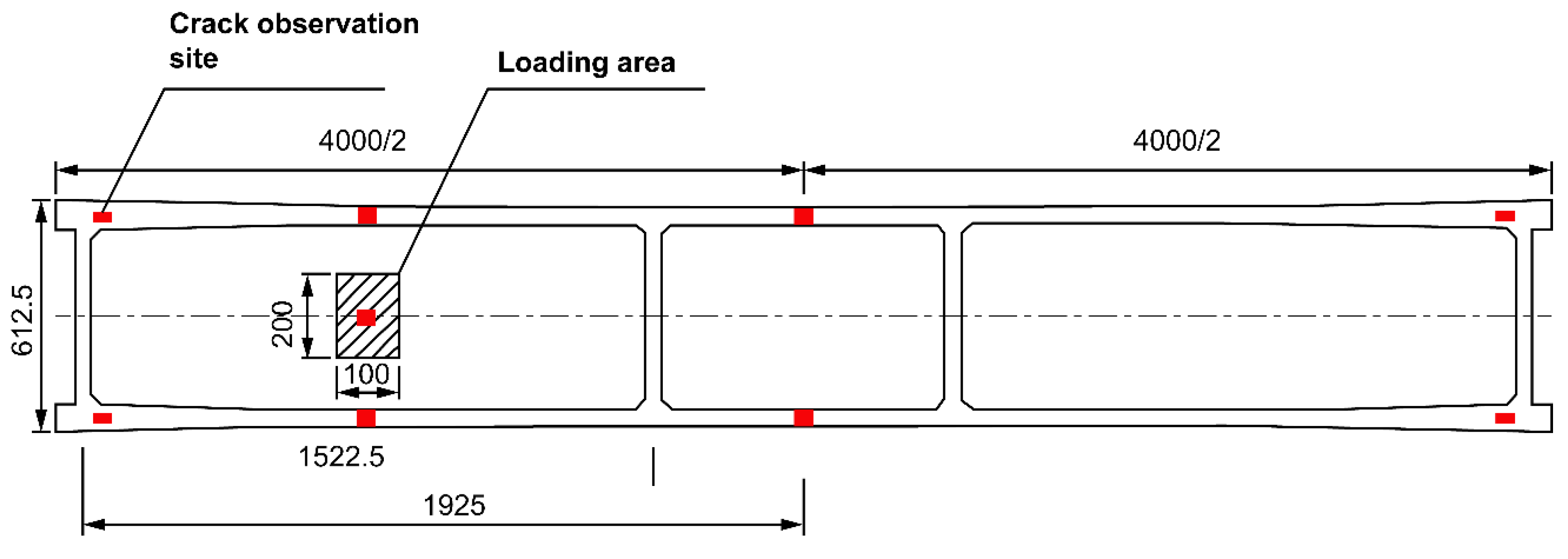
When designing the geometry of the tested beam, the size of the operating space and loading capacity of the laboratory fatigue tester should be taken into consideration. The length of the beam is 4 m, and the bottom dimension at the end of the beam is appropriately thickened and reinforced with more steel. The test beam was designed based on the standard drawing of the 16-m T-beam issued by the Ministry of Transportation in China, with a 1:4 scale reduction. The calculated span of the test beam was 3.85 m, and the two T-beams, wet joints, and transverse partitions were simultaneously cast as one. The concrete grade used was C40. The cross-sectional arrangement of the test beam is shown in
Figure 1, and the top view is shown in
Figure 2. The test beam was designed with two mid-transverse partitions. A one-way slab with an aspect ratio of 2.8 was considered as the focus of the study.
The reinforcement of the test beam was the same as that of the standard drawing 16-m T-beam. For an equal reinforcement rate, the internal reinforcement of the test girders was 1/4 of the internal reinforcement diameter of the 16-m T-girders, thus ensuring the similarity of the structure. The test beam deck plate reinforcement is shown in
Figure 3 (The numbers in the circle indicate the steel number). Five test beams were fabricated, three of which were reinforced; the specific working conditions are listed in
Table 3. After the test beams were fabricated, they were maintained for 28 d for beam reinforcement treatment and testing.
Three test beams were selected and reinforced with CFRP cloth, CFRP mesh, or strip steel plates. The reinforcement method is external paste type, to paste one layer of reinforcement material. Since the one-way slab is stressed on the short side, CFRP sheets and steel plates are only reinforced in the cross-bridge direction. According to the 1:4 scaling requirements, the width of the CFRP cloth was 50 mm and the clear distance between the fabric strips was 50 mm; cross-bridge reinforcement and a 100-mm-wide compression bar were set at the end of the fabric strips. The CFRP mesh was directly reinforced because it was difficult to scale the design down. The reinforcement area percentages of the bridge deck slab with the CFRP sheet, CFRP grid, and strip steel plate are 50%, 100%, and 50%, respectively. The reinforcement area percentages with the CFRP sheet and strip steel are the same.
Before reinforcement, the test beam was fatigue loaded. The fatigue load level was set to 0.515. The loading point was selected as the middle of the one-way slab near the end of the beam, and the loading area was 0.1 m × 0.2 m. When signs of lattice cracks appeared under the deck slab and the width of the main crack reached 0.1 mm, the fatigue loading was stopped; at this time, the signs of cracks appeared in the test beam, as shown in
Figure 4. Then, the test beam was removed from the loading device, and the deck slab was reinforced. The reinforced test girders are shown in
Figure 5.
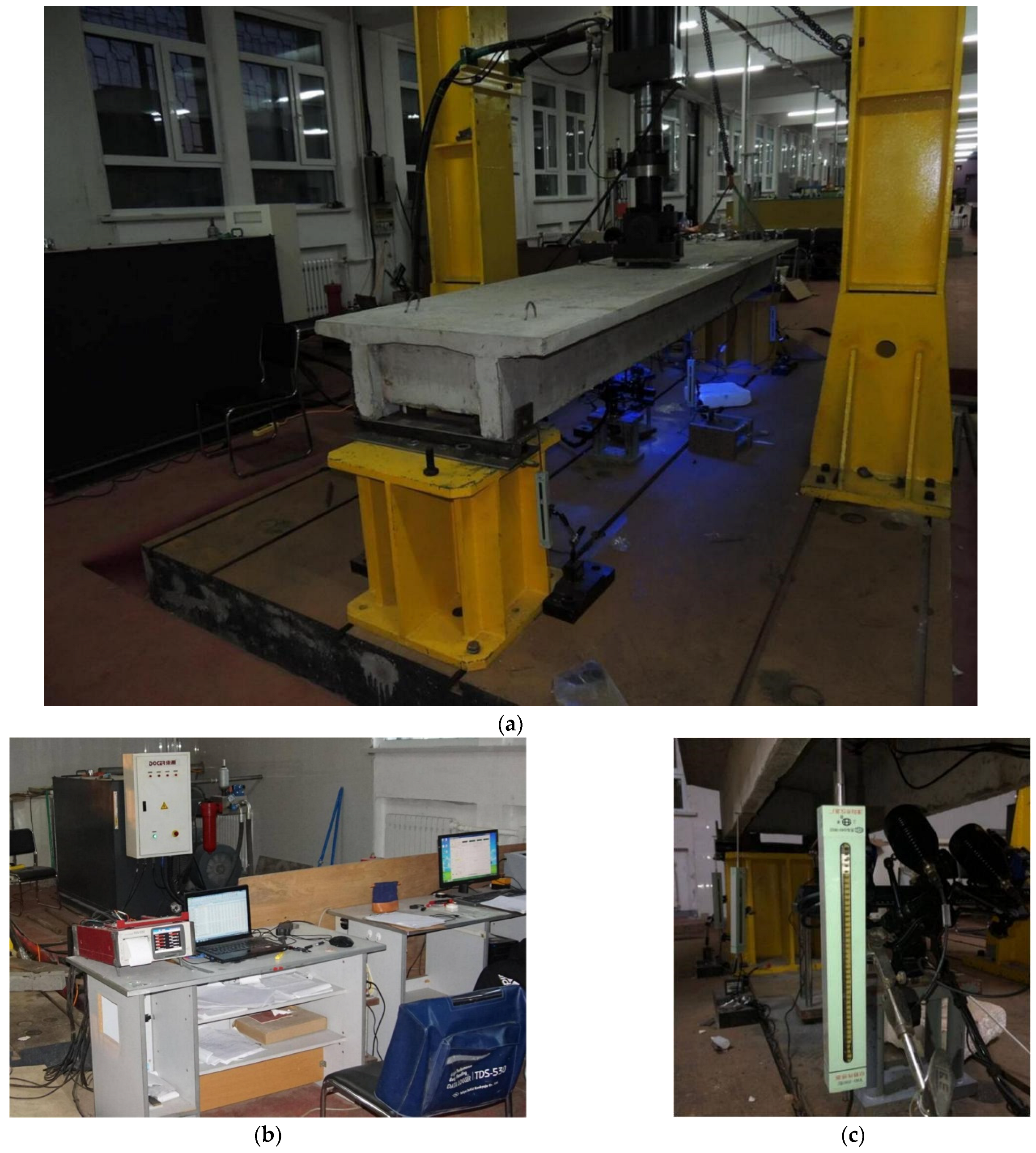
2.3. Test Setup, Instrumentation, and Loading Procedures
A servo actuator was used to simulate the wheel load loading. The loading area was 0.1 m × 0.2 m, and fine sand was placed under the loading plate. A PLS-500 electro-hydraulic servo dynamic and static test system was used for the static load and fatigue tests. The system consists of a servo linear actuator, a constant pressure servo pump station, an oil distribution module, a full digital servo controller, a computer data processing system, a loading frame and attachments, etc. The electro-hydraulic servo-controlled actuator is used to load the tested beam. The fatigue test was set to constant-amplitude fatigue, and the loading is shown in
Figure 6. The test process is carried out in a closed-loop control.
In addition to using concrete strain gauges, the concrete strain values during fatigue were collected using a TDS-530 high-speed static data acquisition instrument. The YHD-200 model was selected as the displacement sensor. A crack observer and ARAMIS professional non-contact measurement systems were used to observe the cracks. The site layout is shown in
Figure 7.
Formal testing began after pre-loading was completed, and the system was normal. A static load test was performed using monotonic graded loading. Each level of loading is generally 1/10 of the ultimate load. For the fatigue test, the minimum value of the load was 1 kN, and the maximum value was 37.4 kN. The control method of the process spectrum is “force control”, loaded with a sinusoidal load wave. The loading frequency was set at 5 Hz. The predetermined numbers of fatigue cycles were: 2, 5, 10, 50, 100, 150, and 200, and the unit was “ten thousand times”. After the numbers of fatigue cycles were reached, the test machine automatically stopped, and a static load test with Fmax as the loading force was performed. The fatigue damage criteria were fatigue fracture of reinforcing steel or a positive section crack width of 1.5 mm.
3. Results and Discussion
3.1. Failure Modes and Crack Development Patterns
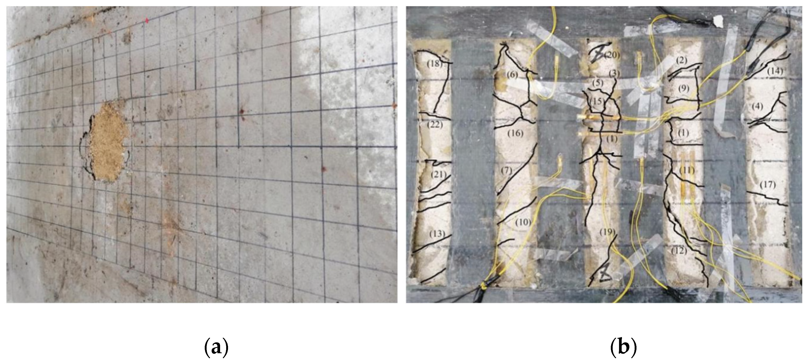
A static load damage test was performed on the PL1 test beam with a cracking load of 31.45 kN and ultimate load of 74.23 kN. Punching shear damage occurred at the loading point of the bridge deck slab, as seen in
Figure 8. The minimum value of the reciprocating load of the PL2–PL5 test girders was 1 kN, and the maximum value was 37.4 kN. The maximum value was because of the PL1 ultimate load and fatigue load level of 0.515. The PL2 deck slab exhibited a fatigue fracture at the main crack. At the moment of fracture, the concrete in the compressed area at the loading point was crushed, and punching shear damage occurred, as shown in
Figure 9. During the fatigue test, all reinforced deck slabs exceeded two million fatigue cycles. The fatigue life was approximately 1.6 to 2 times that of an unreinforced beam. The reinforced deck slab was fatigue-fractured at the main crack, and a fracture sound could sometimes be heard at the time of fracture. At the moment of fracture, the concrete in the pressure zone at the loading point was crushed, and punching shear fatigue damage occurred. As the PL4 cracks were difficult to observe, the CFRP mesh was broken and lifted for observation after the test. The fatigue damages of PL3, PL4, and PL5 are shown in
Figure 10,
Figure 11 and
Figure 12. The fatigue damage of the reinforced deck slab appeared as brittle damage. The area around the hole was similar to that of the fatigue damage of the unreinforced deck slab, and it was smaller than the area around the hole in the static load damage. Regarding the fatigue failure characteristics, the fatigue failure of reinforced bridge deck slabs is mainly in the form of brittle fracture of reinforced steel. In fatigue failure, the reinforcing material peels. Finally, under the shear of the load, the steel will be pulled out by fatigue, and the bridge deck will collapse and lose its bearing capacity. Overall, after reinforcement, the bridge deck slab improved its ability to resist dynamic loads, reduced its brittleness, and slightly improved its ductility.
In the fatigue test, the crack development in the reinforced bridge deck slabs was relatively slow. The PL2 deck slab cracks were divided into four stages. In the initial development stage, fine cracks developed mainly in one direction. In the stable development stage, transverse and longitudinal cracks with lattice-like signs were observed. In the rapid development stage, cracks with a seam width of 0.2 mm or more propagated rapidly, and new cracks appeared between the existing cracks. In the damage stage, the longitudinal cracks instantly became the primary damage cracks, and the crack width reached 0.45 mm. The cracks were roughly distributed radially, with lattice-like signs in the center, and the number and length of crack roots were greater than those in the static load test.
PL3, PL4, and PL5 were subjected to fatigue loading before reinforcement approximately 500,000 to 750,000 times. Reinforcement was performed when cracks with lattice signs appeared. The fatigue crack development processes of PL3 and PL5 bridge deck slabs were similar. During the initial development stage, cracks with lattice signs developed to some extent with the increase in fatigue loading cycles; however, because of the restraining effect of the reinforcement material, lattice-like cracks tended to propagate slowly. During the stable development stage, transverse, longitudinal, and lattice cracks formed. In the rapid development stage, cracks with a width of more than 0.2 mm rapidly increased, and new cracks appeared between the existing cracks. At this point, the concrete and reinforcement material interfaces began to separate. In the damage stage, transverse or oblique cracks quickly became the main cracks of destruction. The crack width reached 0.4–0.5 mm, and the cracks were roughly radially distributed during damage. There were lattice-like signs in the center, and the number and length of crack roots were greater than those of unreinforced PL2. The PL4 deck slab, because of the two-way restraint effect of the CFRP mesh, had a lower crack expansion speed than those of PL3 and PL5. The number and length of crack roots were smaller than those of PL3 and PL5 during the damage stage. There were no radial cracks, and the punching and cutting cracks at the junction of the deck slab and beam rib were the main damage cracks. The experiments showed that the tensile effect of the reinforcement material restrained the development of longitudinal deck slab cracking.
The fatigue cracks that developed in the PL2, PL3, and PL5 deck slabs are summarized in
Table 4. The cracks in PL4 are not included in
Table 4 because they were not observable. The number of cracks in the reinforced deck slabs at the stable development stage was the same as that in the unreinforced deck slab. The number of major cracks in the rapid development stage was six to eight (37.5–50%) more than that in the unreinforced deck slab. This indicates that the reinforced deck slabs have a greater density of cracks, and the reinforcement material limits the development of major cracks in the stable development stage. The slow propagation of the main cracks leads to many new cracks in the bridge deck in the rapid development stage, and the crack density increases accordingly. The slow propagation of the main cracks substantially prolongs the service life of the bridge deck.
3.2. Concrete and Reinforcement Strain Variation Patterns
The data obtained from the measurement and observation system were combined and plotted against the change in the concrete tensile strain under the test beam slab with the number of fatigue cycles, as shown in
Figure 13. PL4 is missing in
Figure 13 because the observation system could not directly observe the PL4 concrete tensile strain. As shown in
Figure 13, the concrete tensile strain exhibited linear growth with plastic accumulation damage during the early stage of fatigue. The concrete plastic deformation under the slab slowed down at the middle stage of fatigue, and at the late stage of fatigue, the concrete tensile strain increased rapidly, while the damage continued to increase. The transverse tensile strain of the PL2 bridge deck slab was always larger than the longitudinal tensile strain, and the transverse tensile strain became the main tensile strain for fatigue damage in the late fatigue stage. The transverse tensile strains of the PL3 and PL5 bridge deck slabs developed slowly with the restraining effect of the reinforcement material. In comparison, the longitudinal tensile strain developed more rapidly than the transverse tensile strain and finally became the main tensile strain of the fatigue damage. From the reinforcement materials, the performance of the CFRP cloth in inhibiting the cumulative fatigue deformation of the tensile strain was better than that of the strip steel plate. Regarding the growth rate, the growth rate of the concrete transverse tensile strain of reinforced deck slabs is significantly lower than that of unreinforced deck slabs. As shown in
Figure 13b,c, at the late stage of degradation, the degradation rate of unreinforced concrete in the longitudinal direction of the bridge deck slab is greater than that of transverse concrete. This indicates that in one-way slab reinforcement, two-way reinforcement is more beneficial for extending the remaining life of the bridge deck slab.
Figure 14 shows the variation in the tensile strain of the reinforcement in the test beam deck slab under fatigue loading. As shown in
Figure 14, the transverse tensile strain of PL2 was closer to the longitudinal tensile strain, and its value was lower than those of PL3 and PL5. In the middle and early stages, the longitudinal tensile strain was less than the transverse tensile strain; in the later stage, the longitudinal tensile strain exceeded the transverse tensile strain. Finally, the longitudinal tensile strain significantly increased. The transverse tensile strain of the PL4 bridge deck was relatively close to the longitudinal tensile strain, and its value was lower than those of PL3 and PL5. When the fatigue cycle is 1 million times, the incremental value of the transverse tensile strain of reinforcing steel in the reinforced deck is approximately 50–75% of that of the unreinforced deck, and that of the longitudinal tensile strain of reinforcement is approximately 40% to 50%. In terms of growth rate, the degradation process of reinforcement steel in reinforced deck slabs is slower than in unreinforced deck slabs. These test results indicate that the CFRP mesh can strengthen the bridge deck in both directions, and the fatigue damage of the steel bars develops slowly after the bridge deck is reinforced.
3.3. Deflection Development and Fatigue Degradation Patterns
Figure 15 shows the changes in the deflection under the PL2–PL5 bridge deck slabs with fatigue loading. The deflection developed faster at the beginning of the test and near the fatigue damage. In the middle of the test, the deflection developed smoothly. The deck plate deflection was the largest when the fatigue life was reached. In the middle of the test, the growth rate of the reinforced deck plate deflection was smaller than that of the unreinforced deck plate, and the deflection of the reinforced deck plate was slightly smaller than that of the unreinforced deck plate for the same number of fatigue cycles. The deck plate reinforced with strip steel plates was the first to experience stiffness degradation, earlier than CFRP-cloth- and CFRP-mesh-reinforced deck slabs by approximately 500,000 cycles. The curve of deflection change in this test is identical to the curve shape reported in the literature [
7], both of which are in the late fatigue stage, and the bridge deck slabs are rapidly damaged.
The degree of deterioration
D is an index characterizing the deterioration condition of the bridge deck plate, which differs from the linear cumulative fatigue damage criterion and is calculated according to the following equation:
where
;
is the measured value of deflection under a slab under a live load;
is the theoretical deflection value of the full section under a live load, taken from the deflection value at a static load to the upper limit of fatigue loading before the fatigue test;
is the theoretical deflection value of the cracked section under a live load, taken from
.
Using Equation (1), the fatigue test deflection data were calculated for the degradation degree
D, and the
D–N relationship curve was plotted, as shown in
Figure 16. The degradation is not linear but non-linear cumulative fatigue damage. The degradation degree
D develops with the number of fatigue
N in three phases. The initial phase is a slow deterioration phase, with a deterioration degree
D value of less than 0.1, accounting for approximately 20% of the life. The late degradation was similar for the reinforced and unreinforced decks. In the middle stage, the deterioration rate of the reinforced deck plate decreased significantly. From fatigue cycles 500,000 to 1.8 million, the
D of the unreinforced plate increased from 0.1 to 0.7. From 1.2 million to 2.8 million fatigue cycles, the
D of the strip-steel plate reinforcement developed from 0.1 to 0.7. From 1.2 million to 3.2 million fatigue cycles, the
D of the CFRP cloth reinforcement developed from less than 0.1 to 0.7. Therefore, the deterioration rate of the reinforced deck was significantly slower than that of the unreinforced deck, and considering the reinforcement material, the CFRP cloth was better than the strip steel plate at limiting the deterioration rate.
The deterioration value
is an indicator of the degree of deterioration of the bridge deck at each moment and is calculated according to the following formula:
where
is the measured deflection under a live load after the fatigue load cycle;
is the measured deflection under a live load after the (
i − 1)th fatigue load cycle.
Using Equation (2), the fatigue test deflection data were subjected to the deterioration value
calculation, and the
–
N relationship curve was plotted, as shown in
Figure 17.
did not vary linearly with the number of fatigue cycles. At the beginning of fatigue,
developed linearly with small values. In the middle of fatigue,
did not change significantly, and at the end of fatigue,
increased dramatically. At 1 million fatigue cycles,
of the unreinforced deck plate was approximately 0.2, nearly 2 times larger than the reinforced bridge deck slab.
of the CFRP cloth and steel plate strip reinforced deck plates were approximately 0.1, and
of the CFRP mesh reinforced deck plate was less than 0.1. This indicates that reinforcement material can reduce the deterioration value of the deck plate by approximately 50% during the fatigue progression period, and the CFRP cloth is better than the strip steel reinforcement at suppressing the deterioration value of the deck slab.
The stiffness reduction factor
is an index characterizing the deterioration of the bridge deck plate stiffness with fatigue development and is calculated according to the following equation:
where
is related to the load level S and number of load cycles N;
is the deflection deformation value of the load action after the reciprocal load action, then the static load test, corresponding to the upper limit of the reciprocal load.
Using Equation (3),
was calculated for PL2–PL5 under fatigue loading, and the
–
N relationship curve was plotted, as shown in
Figure 18.
generally decreased linearly with the number of fatigue cycles. The
of the unreinforced deck decreased faster than those of the reinforced decks. At 1 million fatigue cycles, the
for each unreinforced and reinforced deck was around 0.5. This indicates that the stiffness degradation process is similar in the early stages of fatigue loading. When the fatigue loading was at 2 million cycles, the unreinforced deck
was approximately 0.05, and the reinforced deck
was approximately 0.3. This indicates that in the middle and later stages of fatigue loading, that is, after the appearance of fatigue cracks, the stiffness of the bridge deck decreases slowly, and the reinforcement material reduces the stiffness deterioration of the bridge deck, thereby extending its remaining life.
3.4. Effect of Reinforcement on the Service Life of Bridge Decks
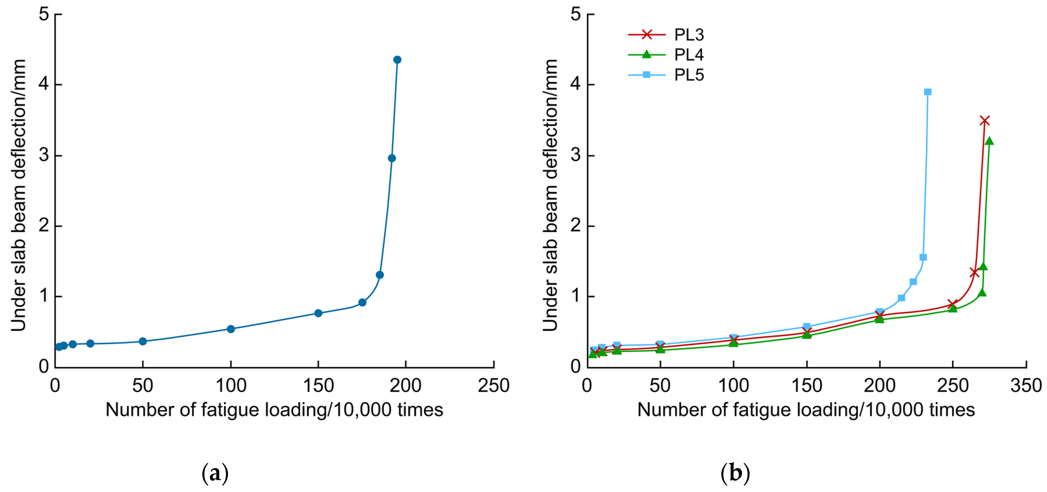
The comparative life analysis of fatigue reinforcement based on the under-slab deflection test data is shown in
Figure 19 and plotted against the number of fatigue cycles before reinforcement for the PL3–PL5 test beams.
Compared with PL2, the late fatigue inflection points and final damage numbers increased by 82.9% and 75.4% for PL3, 85.1% and 78.9% for PL4, and 52% and 53.3% for PL5, respectively. The CFRP cloth and CFRP mesh significantly improved the fatigue resistance of the deck plate, and the strip steel plates showed some improvement in the fatigue resistance of the bridge deck slabs. The CFRP cloth and CFRP mesh lasted 22.1–25.6% longer than the bridge deck slabs reinforced with strip steel plates. In general, after fatigue damage occurred in the bridge deck plate, if the deck plate was reasonably reinforced, the fatigue life of the bridge deck plate was extended, and the reinforcement effect of the CFRP cloth and CFRP mesh was better than that of the strip steel plate under the same fatigue load.
The cumulative damage degree
D of the bridge deck slab is based on the linear cumulative fatigue damage criterion, and is calculated according to the following equation:
where
ND is the cumulative number of fatigue cycles performed, and
Nf is the cumulative number of fatigue cycles when the fatigue damage is reached.
Previous research [
48] provides the relationship between the deterioration process and cumulative damage degree.
D was 0–0.2 during the latent period, 0.2–0.5 during the progressive period, 0.5–0.8 during the accelerated period, and 0.8 to 1.0 during the deterioration period. From the perspective of prevention and preservation, Japan’s longlife repair plan states that the reinforcement period after the bridge deck is damaged must be between the advanced and accelerated periods. A previous study [
7] determined that the reinforcement period of the PL3–PL5 bridge decks after damage is approximately at the end of the progress period (
D = 0.41), which is similar to the longlife repair concept of the Japanese bridge deck and conforms to the prevention and preservation strategy. From the test data of PL3–PL5, after the bridge deck is reinforced once, the service life of the bridge deck is extended by approximately 53.3–78.9%, indicating that the reinforcement has a significant influence on the service life of the bridge deck.
In terms of reinforcement materials, lightweight, high-strength, and corrosion-resistant CFRP materials have better fatigue reinforcement prospects than strip steel. Therefore, CFRP cloth strip reinforcement is more suitable for the fatigue reinforcement of bridge deck slabs.
3.5. Discussion of the S-N Curve of Bridge Deck Slabs under Fatigue Reinforcement
Wang [
49] established a fatigue life prediction model for reinforced concrete ribbed girder bridge deck slabs based on fatigue damage product theory and test data under fatigue loading of concrete deck slabs with wheel movement, and the resulting
S-N curves were as follows:
where,
Fi is the base load value (KN),
Fu is the ultimate punching shear load capacity of the concrete deck slab (KN), and N is the number of cycles.
Combining the fatigue test data in this paper and the punching and cutting theory of the bridge deck slab, the
S-N curve of the fatigue strengthened reinforced concrete ribbed girder bridge deck slab is obtained on the basis of Equation (5), as shown in Equation (6):
where
Fu,c is the impact shear- bearing capacity of the bridge deck plate after reinforcement.
In the literature [
7], the fatigue performance of reinforced concrete bridge deck slabs with FRP material reinforcement was studied, and the
S-N curve of reinforced concrete slabs was established, as shown in Equation (7):
where
PSX.C is the punch-cut load capacity of the reinforced concrete deck slab reinforced by FRP.
Comparing Equations (6) and (7), it can be concluded that the two
S-N curves have the same form and the parameters do not differ much; however, the slope of the
S-N curve of Equation (6) is smaller, and the curve is relatively flat. Since a steel–concrete composite girder deck slab was the target in the literature [
7], this indicates that the
S-N curves of the reinforced deck slab will be different depending on the type of deck slab.


