

Effect of Fiber Wrapping on Bending Behavior of Reinforced Concrete Filled Pultruded GFRP Composite Hybrid Beams
 , ,
, ,  ,
,
Abstract
:1. Introduction
2. Experimental Section
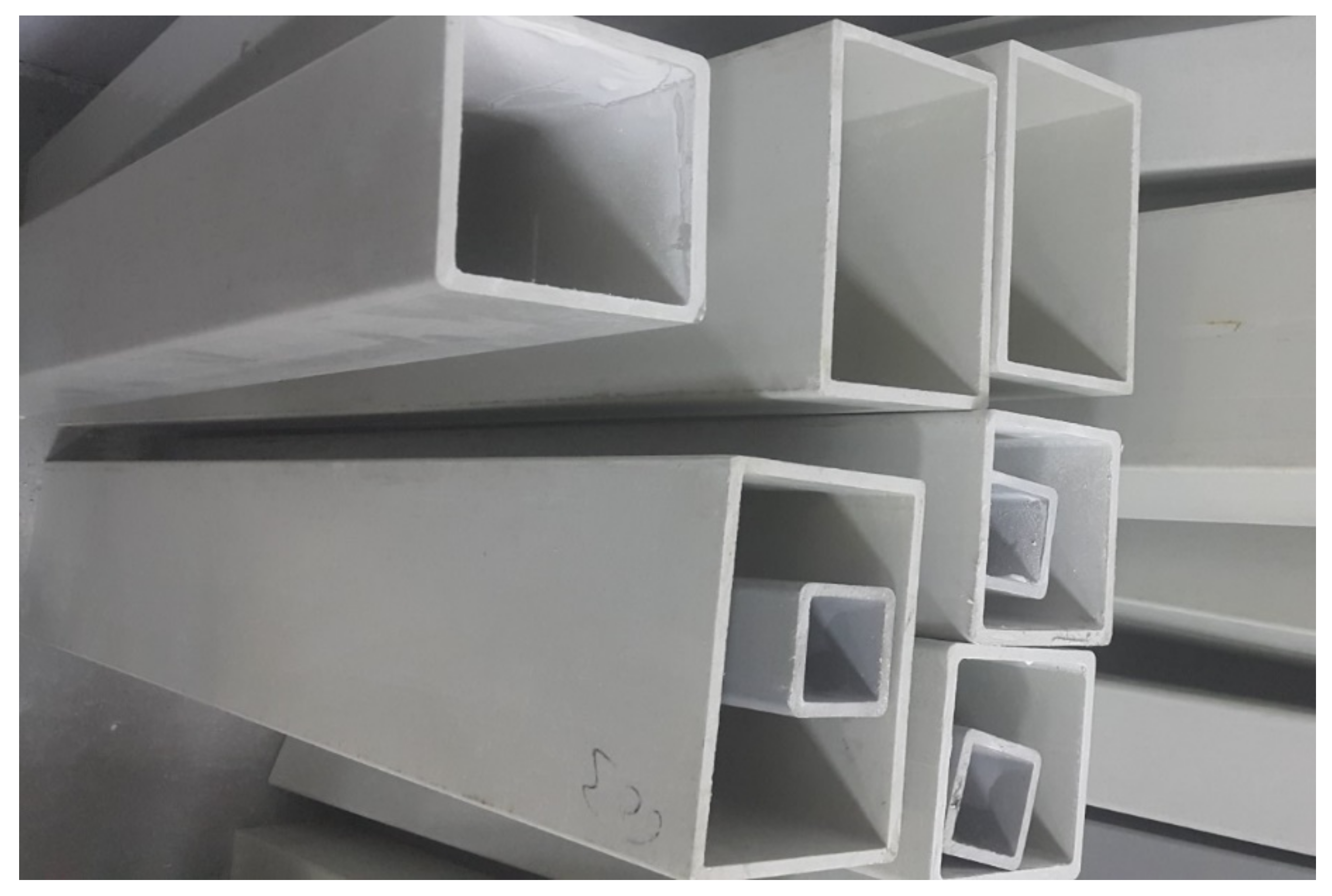
2.1. Properties of Pultruded GFRP Profile
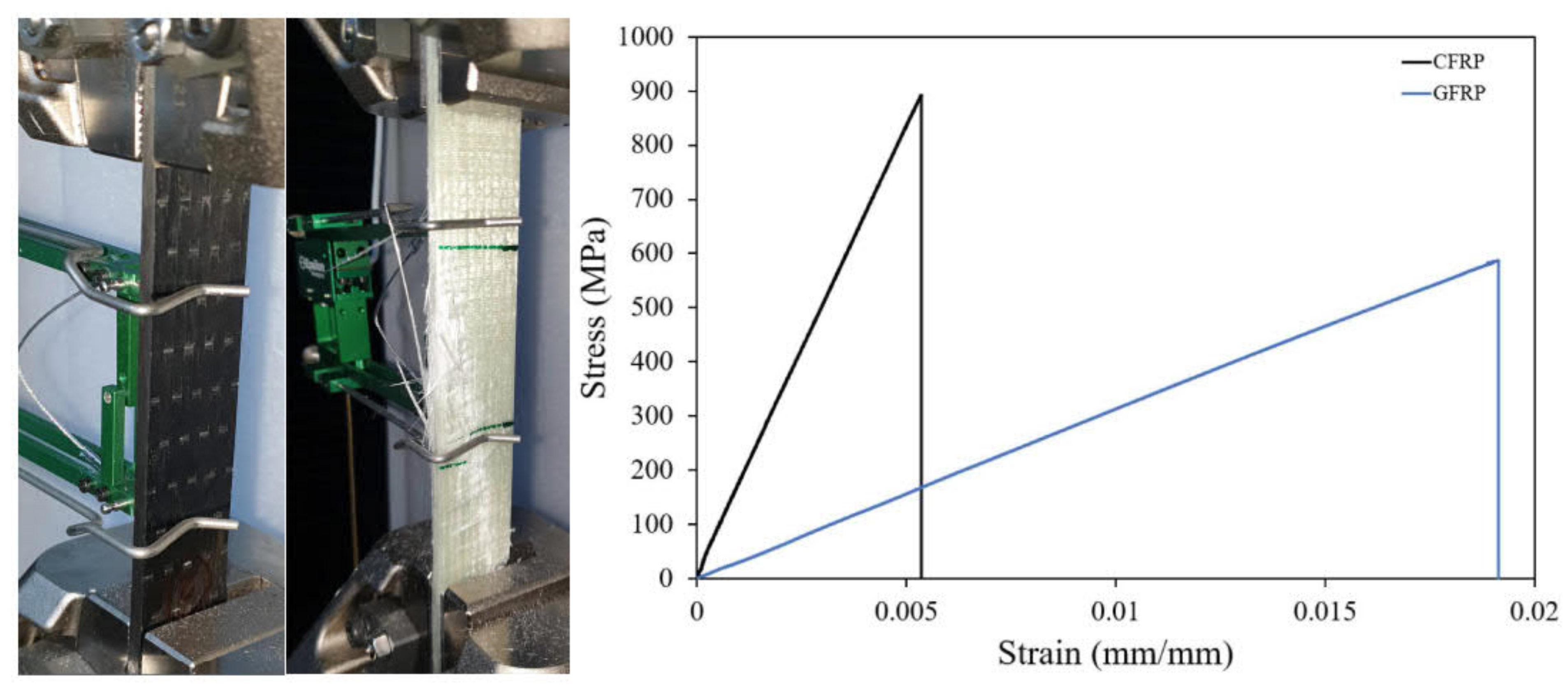
2.2. Properties of GFRP/CFRP Fabric
2.3. Properties of RC
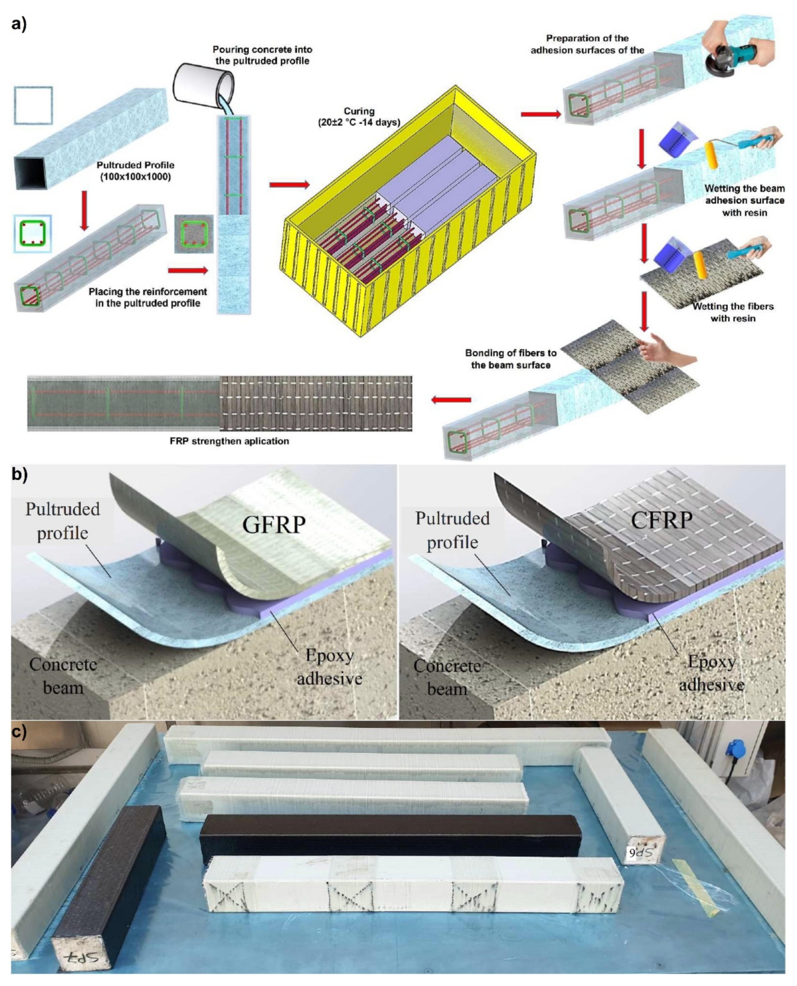
2.4. FRP Wrapping Application
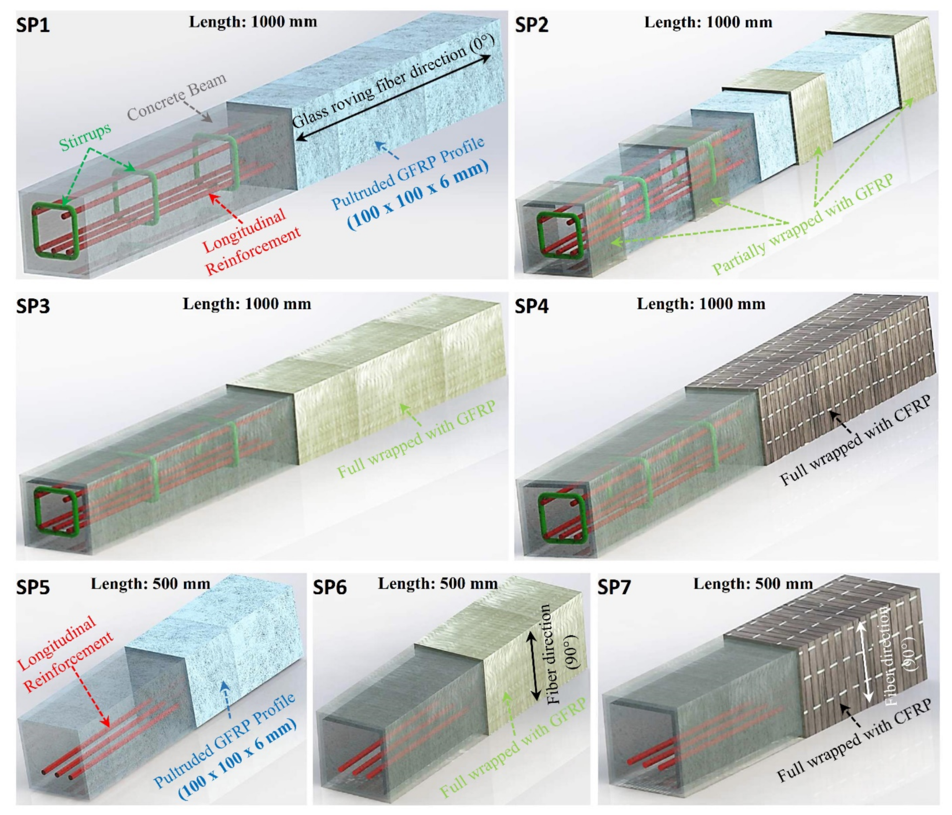
2.5. Test Specimens
2.6. Test Setup
3. Test Results
4. Damage Analysis
5. Conclusions
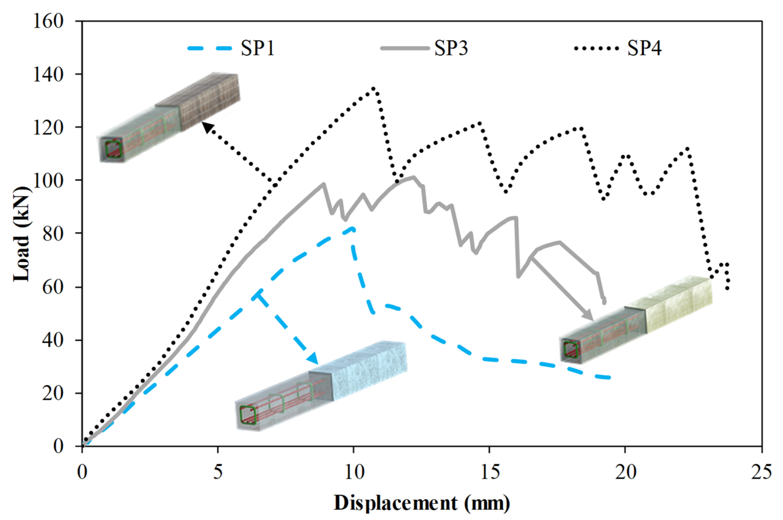
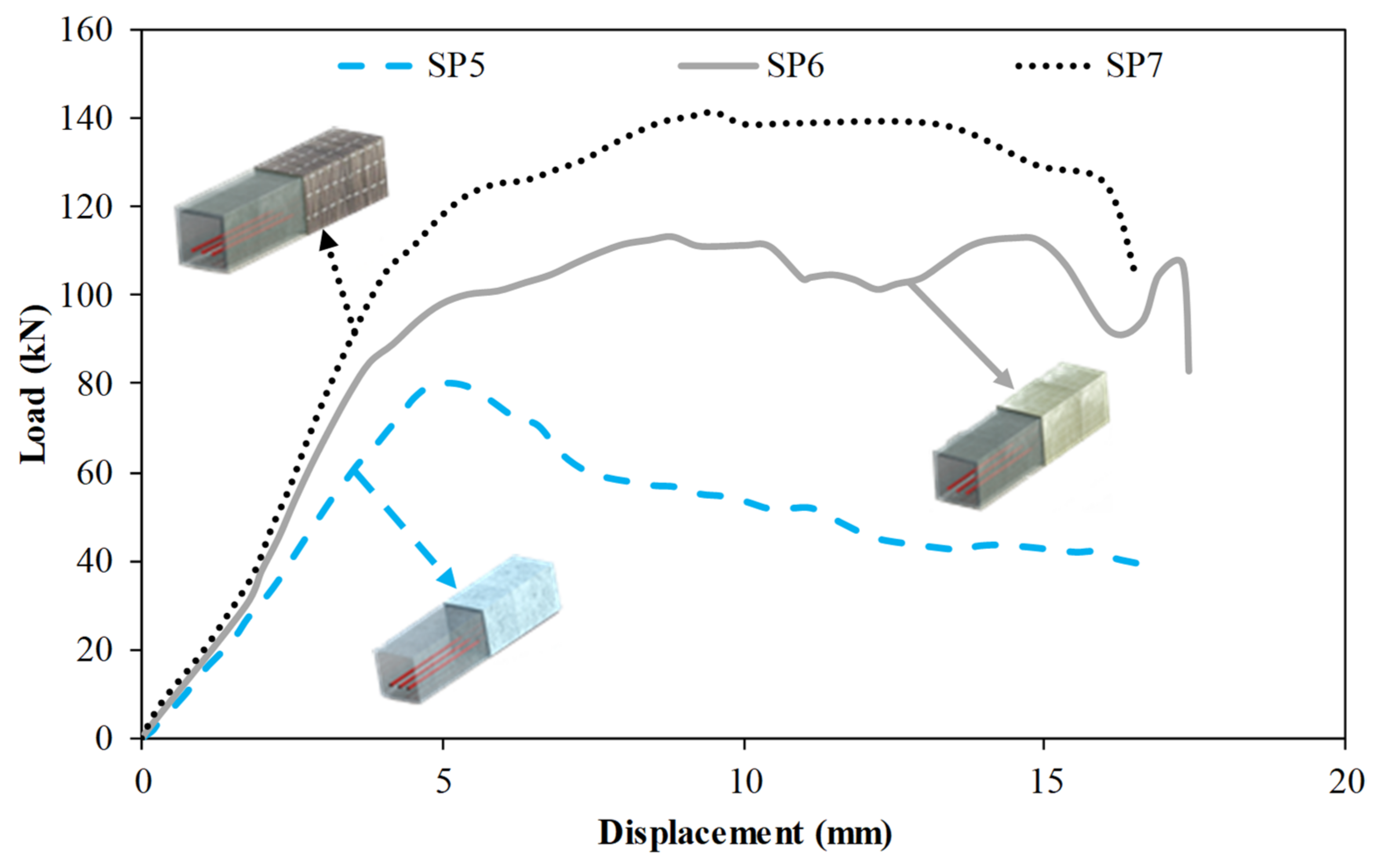
- Partial GFRP, GFRP, and CFRP wrapping effect increased the initial stiffness of beams of 1000 mm length by 15.6%, 33.7%, and 48%, respectively. In 500 mm beams, GFRP and CFRP increased the initial stiffness with a full wrapping effect of 44.2% and 65.4%, respectively. When the load carrying capacities are compared to beams of 1000 mm length; the partial GFRP, GFRP, and CFRP wrap effect increased by 4.3%, 24%, and 64.4%, respectively. These results indicate that the CFRP wrapping application is more effective than the GFRP wrapping application.
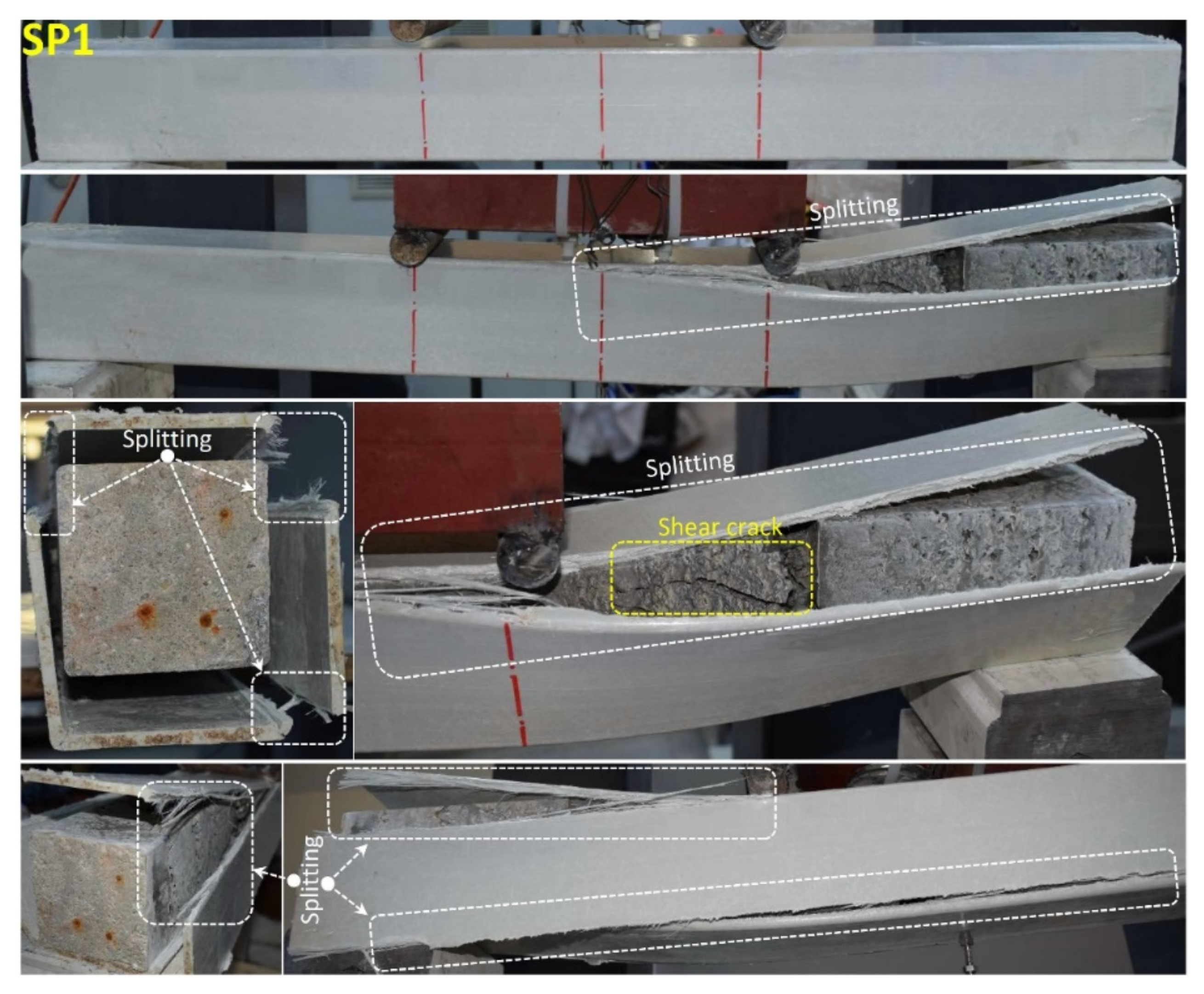
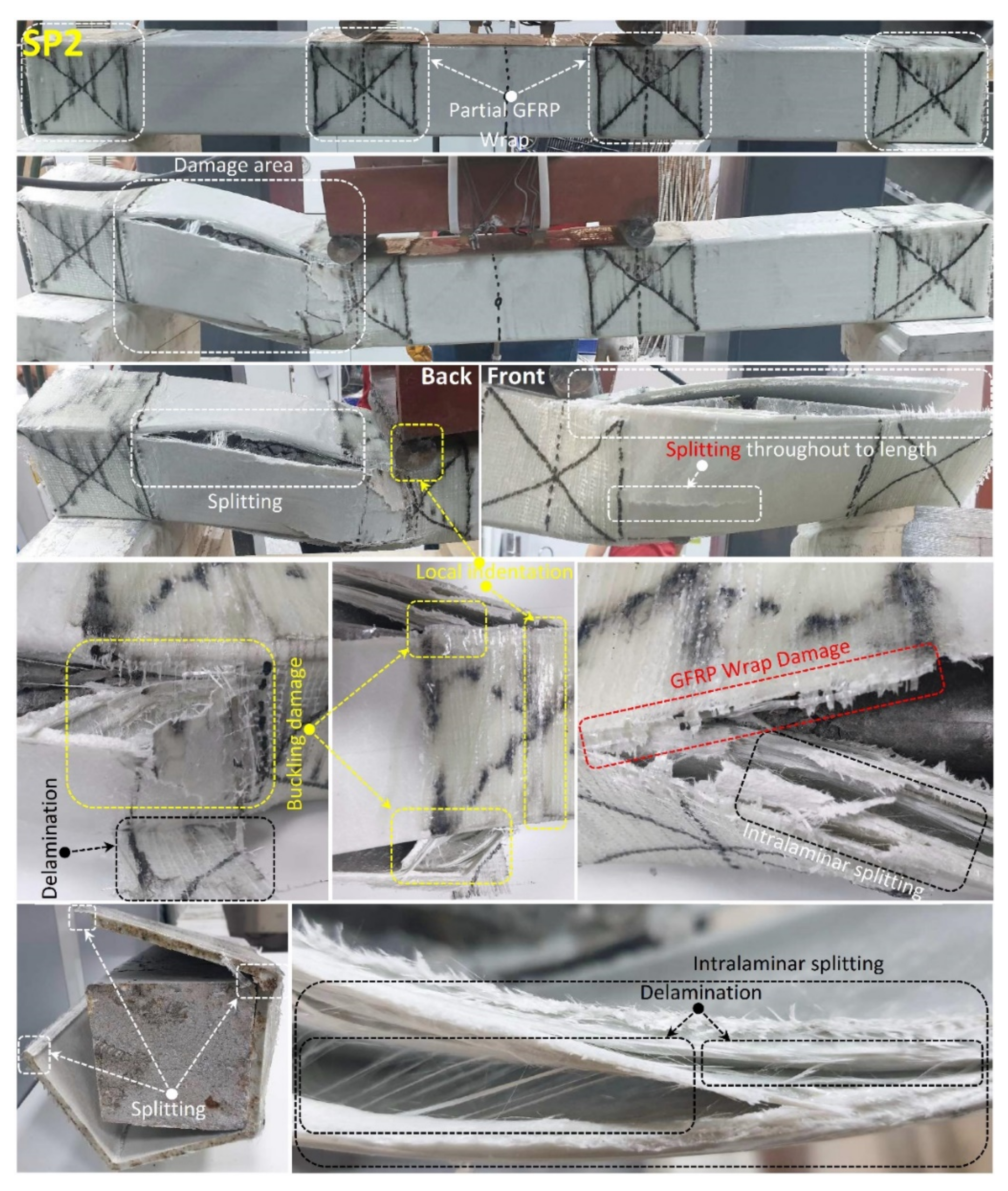
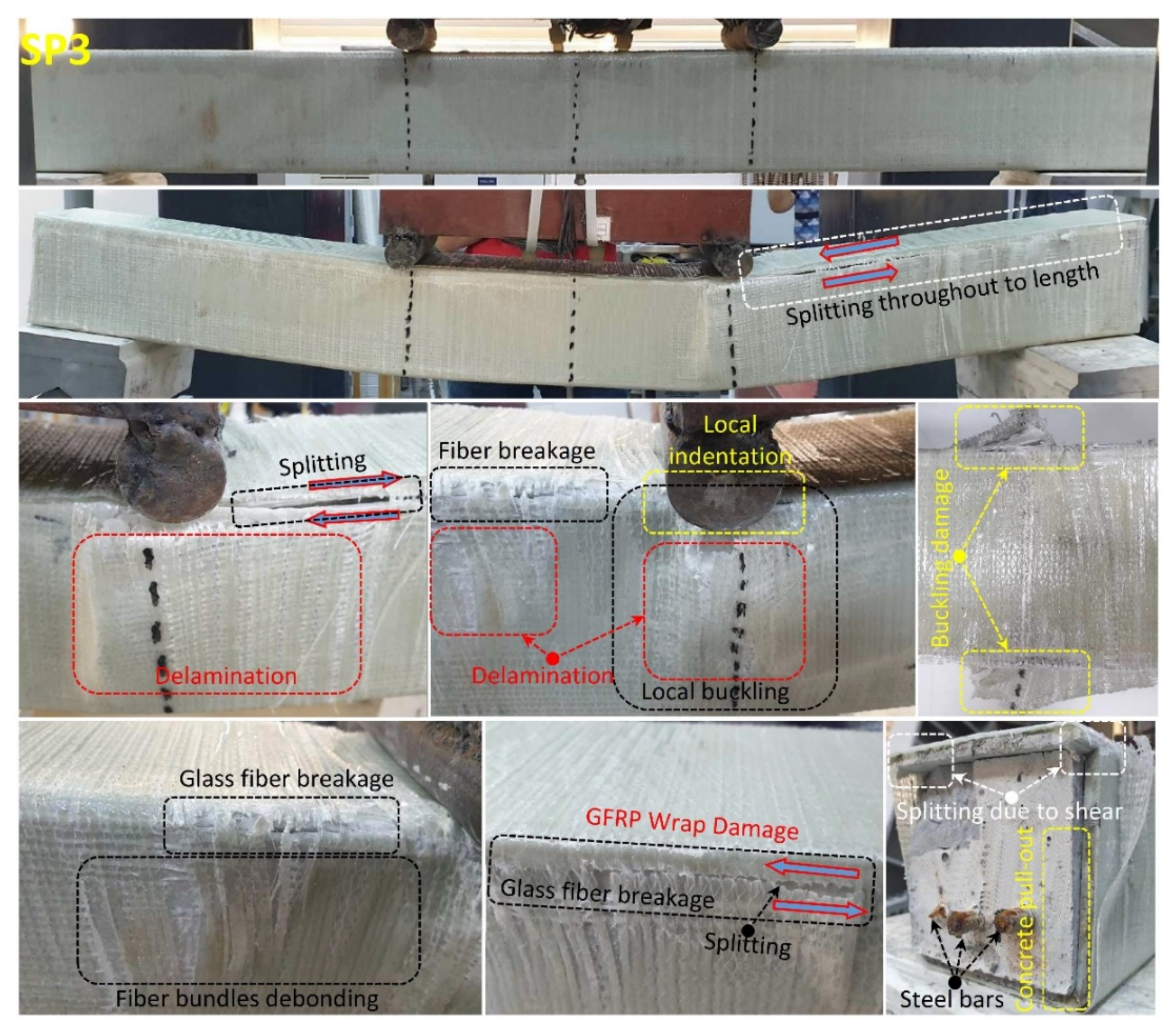
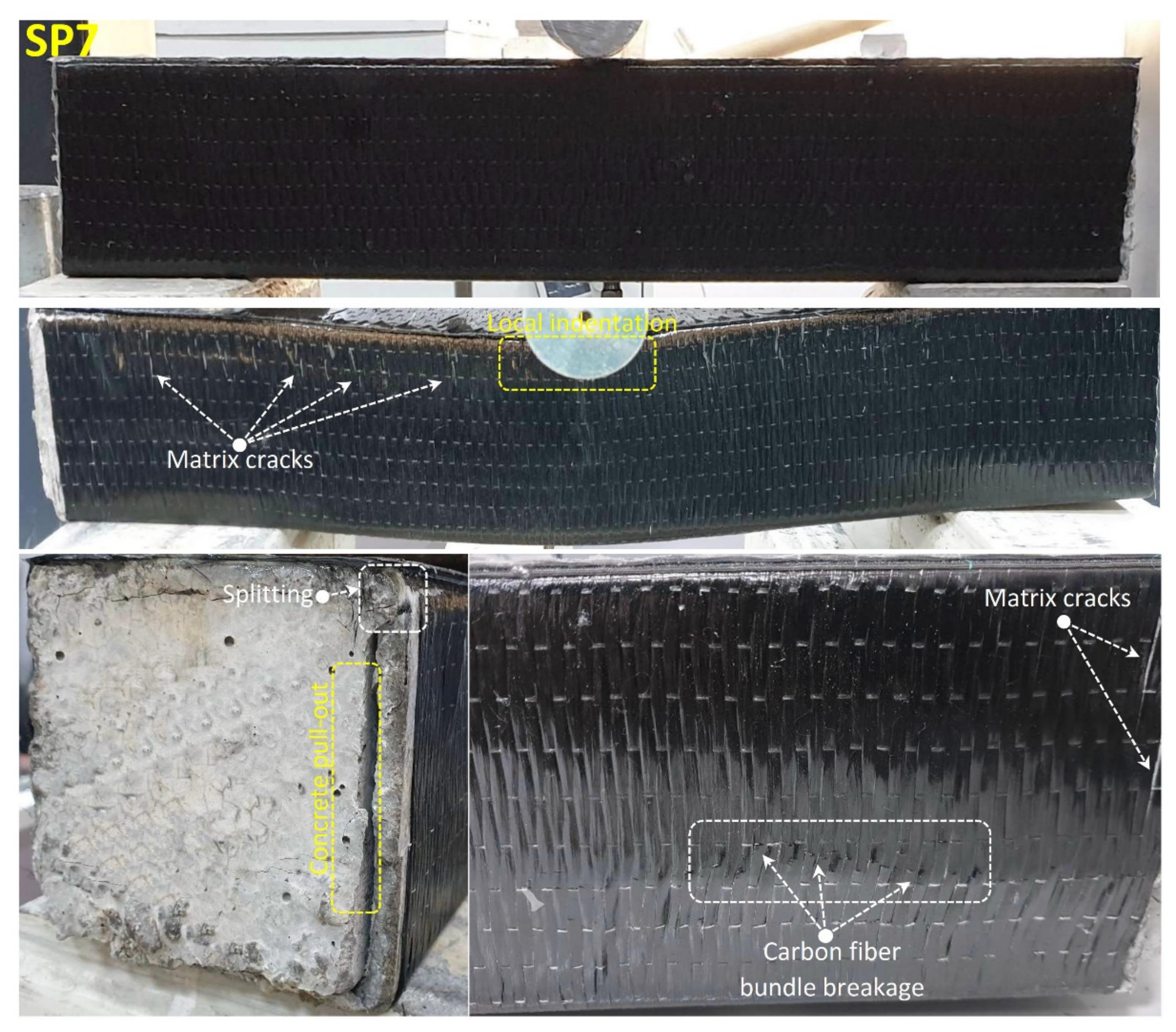
- Splitting damages were dominant especially in the corner regions of pultruded GFRP profiles while local buckling damages were dominant in the compression regions of the indentor in the wrapped samples and the cleavage damages starting from the buckling regions under the FRP wrappings progressed. Delamination, fiber bundle debonding, and fiber breakage damages in GFRP and CFRP wrappings were concentrated in the local buckling damage area. Fiber breakage damages begin with the effect of splitting due to shear damages in pultruded GFRP profiles.
- Using FRP wrapping on pultruded beams infilled with reinforced concrete significantly improved ductility, load capacity, and energy dissipation capacity. These gains can be improved by implementing a better interface with reinforced concrete [85] and the pultruded profile and by utilizing different stacking sequences of FRP wrapping [26].
Author Contributions
Funding
Institutional Review Board Statement
Informed Consent Statement
Data Availability Statement
Conflicts of Interest
References
- Du, Y.; Gao, D.; Chen, Z.; Zheng, Z.; Wang, X. Behaviors of FRP confined rectangular concrete-filled thin-walled steel tubular stub columns using high-strength materials under axial load. Compos. Struct. 2022, 280, 114915. [Google Scholar] [CrossRef]
- Huang, L.; Su, L.; Xie, J.; Lu, Z.; Li, P.; Hu, R.; Yang, S. Dynamic splitting behaviour of ultra-high-performance concrete confined with carbon-fibre-reinforced polymer. Compos. Struct. 2022, 284, 115155. [Google Scholar] [CrossRef]
- Jafarzadeh, H.; Nematzadeh, M. Flexural strengthening of fire-damaged GFRP-reinforced concrete beams using CFRP sheet: Experimental and analytical study. Compos. Struct. 2022, 288, 115378. [Google Scholar] [CrossRef]
- Sorrentino, L.; Turchetta, S.; Bellini, C. In process monitoring of cutting temperature during the drilling of FRP laminate. Compos. Struct. 2017, 168, 549–561. [Google Scholar] [CrossRef]
- Obaidat, Y.T.; Heyden, S.; Dahlblom, O. The effect of CFRP and CFRP/concrete interface models when modelling retrofitted RC beams with FEM. Compos. Struct. 2010, 92, 1391–1398. [Google Scholar] [CrossRef]
- Bousselham, A.; Chaallal, O. Mechanisms of Shear Resistance of Concrete Beams Strengthened in Shear with Externally Bonded FRP. J. Compos. Constr. 2008, 12, 499–512. [Google Scholar] [CrossRef]
- Yan, L. Plain concrete cylinders and beams externally strengthened with natural flax fabric reinforced epoxy composites. Mater. Struct. 2016, 49, 2083–2095. [Google Scholar] [CrossRef]
- Moradi, E.; Naderpour, H.; Kheyroddin, A. An experimental approach for shear strengthening of RC beams using a proposed technique by embedded through-section FRP sheets. Compos. Struct. 2020, 238, 111988. [Google Scholar] [CrossRef]
- Defiella, A. Punching shear strength and deformation for FRP-reinforced concrete slabs without shear reinforcements. Case Stud. Constr. Mater. 2022, 16, e00925192. [Google Scholar] [CrossRef]
- Ferracuti, B.; Savoia, M.; Zucconi, M. RC frame structures retrofitted by FRP-wrapping: A model for columns under axial loading and cyclic bending. Eng. Struct. 2020, 207, 110243. [Google Scholar] [CrossRef]
- Mai, A.D.; Sheikh, M.N.; Yamakado, K.; Hadi, M.N.S. Nonuniform CFRP Wrapping to Prevent Sudden Failure of FRP Confined Square RC Columns. J. Compos. Constr. 2020, 24, 04020063. [Google Scholar] [CrossRef]
- Lin, S.; Zhao, Y.-G.; Li, J. An improved wrapping scheme of axially loaded fiber-reinforced polymer confined concrete columns. Compos. Struct. 2019, 226, 111242. [Google Scholar] [CrossRef]
- Godat, A.; Hammad, F.; Chaallal, O. State-of-the-art review of anchored FRP shear-strengthened RC beams: A study of influencing factors. Compos. Struct. 2020, 254, 112767. [Google Scholar] [CrossRef]
- Mofidi, A.; Chaallal, O. Shear Strengthening of RC Beams with EB FRP: Influencing Factors and Conceptual Debonding Model. J. Compos. Constr. 2011, 15, 62–74. [Google Scholar] [CrossRef]
- Yin, P.; Huang, L.; Yan, L.; Zhu, D. Compressive behavior of concrete confined by CFRP and transverse spiral reinforcement. Part A: Experimental study. Mater. Struct. 2016, 49, 1001–1011. [Google Scholar] [CrossRef]
- Sliseris, J.; Yan, L.; Kasal, B. Numerical modelling of flax short fibre reinforced and flax fibre fabric reinforced polymer composites. Compos. Part B Eng. 2016, 89, 143–154. [Google Scholar] [CrossRef]
- Yan, L.; Chouw, N.; Kasal, B. Experimental study and numerical simulation on bond between FFRP and CFRC components. J. Reinf. Plast. Compos. 2016, 36, 305–320. [Google Scholar] [CrossRef]
- Saribiyik, A.; Abodan, B.; Balci, M.T. Experimental study on shear strengthening of RC beams with basalt FRP strips using different wrapping methods. Eng. Sci. Technol. Int. J. 2020, 24, 192–204. [Google Scholar] [CrossRef]
- Aksoylu, C.; Yazman, Ş.; Özkılıç, Y.O.; Gemi, L.; Arslan, M.H. Experimental analysis of reinforced concrete shear deficient beams with circular web openings strengthened by CFRP composite. Compos. Struct. 2020, 249, 112561. [Google Scholar] [CrossRef]
- Saribiyik, A.; Caglar, N. Flexural strengthening of RC Beams with low-strength concrete using GFRP and CFRP. Struct. Eng. Mech. 2016, 58, 825–845. [Google Scholar] [CrossRef]
- Slaitas, J.; Valivonis, J. Full moment-deflection response and bond stiffness reduction of RC elements strengthened with prestressed FRP materials. Compos. Struct. 2021, 260, 113265. [Google Scholar] [CrossRef]
- Zhang, S.; Ke, Y.; Chen, E.; Biscaia, H.; Li, W. Effect of load distribution on the behaviour of RC beams strengthened in flexure with near-surface mounted (NSM) FRP. Compos. Struct. 2022, 279, 114782. [Google Scholar] [CrossRef]
- Madenci, E.; Ozkilic, Y.O. Free vibration analysis of open-cell FG porous beams: Analytical, numerical and ANN approaches. Steel Compos. Struct. 2021, 40, 157. [Google Scholar]
- Gemi, L.; Aksoylu, C.; Yazman, Ş.; Özkılıç, Y.O.; Arslan, M.H. Experimental investigation of shear capacity and damage analysis of thinned end prefabricated concrete purlins strengthened by CFRP composite. Compos. Struct. 2019, 229, 111399. [Google Scholar] [CrossRef]
- Aksoylu, C.; Özkılıç, Y.O.; Yazman, Ş.; Gemi, L.; Arslan, M.H. Experimental and Numerical Investigation of Load Bearing Capacity of Thinned End Precast Purlin Beams and Solution Proposals. Tek. Dergi 2021. [Google Scholar] [CrossRef]
- Özkılıç, Y.O.; Yazman, Ş.; Aksoylu, C.; Arslan, M.H.; Gemi, L. Numerical investigation of the parameters influencing the behavior of dapped end prefabricated concrete purlins with and without CFRP strengthening. Constr. Build. Mater. 2021, 275, 122173. [Google Scholar] [CrossRef]
- Arslan, M.H.; Yazman, Ş.; Hamad, A.A.; Aksoylu, C.; Özkılıç, Y.O.; Gemi, L. Shear strengthening of reinforced concrete T-beams with anchored and non-anchored CFRP fabrics. Structures 2022, 39, 527–542. [Google Scholar] [CrossRef]
- Gemi, L.; Alsdudi, M.; Aksoylu, C.; Yazman, S.; Ozkilic, Y.O.; Arslan, M.H. Optimum amount of CFRP for strengthening shear deficient reinforced concrete beams. Steel Compos. Struct. 2022, 43, 735–757. [Google Scholar]
- Özkılıç, Y.O.; Aksoylu, C.; Yazman, Ş.; Gemi, L.; Arslan, M.H. Behavior of CFRP-strengthened RC beams with circular web openings in shear zones: Numerical study. Structures 2022, 41, 1369–1389. [Google Scholar] [CrossRef]
- Vedernikov, A.; Safonov, A.; Tucci, F.; Carlone, P.; Akhatov, I. Pultruded materials and structures: A review. J. Compos. Mater. 2020, 54, 4081–4117. [Google Scholar] [CrossRef]
- Attia, K.; Alnahhal, W.; Elrefai, A.; Rihan, Y. Flexural behavior of basalt fiber-reinforced concrete slab strips reinforced with BFRP and GFRP bars. Compos. Struct. 2019, 211, 1–12. [Google Scholar] [CrossRef]
- Minchenkov, K.; Vedernikov, A.; Safonov, A.; Akhatov, I. Thermoplastic Pultrusion: A Review. Polymers 2021, 13, 180. [Google Scholar] [CrossRef] [PubMed]
- Li, C.; Guo, R.; Xian, G.; Li, H. Innovative compound-type anchorage system for a large-diameter pultruded carbon/glass hybrid rod for bridge cable. Mater. Struct. 2020, 53, 73. [Google Scholar] [CrossRef]
- Li, C.; Xian, G.; Li, H. Influence of immersion in water under hydraulic pressure on the interfacial shear strength of a unidirectional carbon/glass hybrid rod. Polym. Test. 2018, 72, 164–171. [Google Scholar] [CrossRef]
- Sugiyama, M.; Uomoto, T. Research on Strength and Durability of Gfrp Rods for Prestressed Concrete Tendons. In Fibre-Reinforced Polymer Reinforcement for Concrete Structures: (In 2 Volumes); World Scientific Publishing Co. Pte Ltd.: Singapore, 2003; pp. 727–736. [Google Scholar] [CrossRef]
- Mueller, Y.; Tognini, R.; Mayer, J.; Virtanen, S. Anodized titanium and stainless steel in contact with CFRP: An electrochemical approach considering galvanic corrosion. J. Biomed. Mater. Res. Part A 2007, 82, 936–946. [Google Scholar] [CrossRef]
- Rutkowska, M.; Krasowska, K.; Heimowska, A.; Steinka, I.; Janik, H. Degradation of polyurethanes in sea water. Polym. Degrad. Stab. 2002, 76, 233–239. [Google Scholar] [CrossRef]
- Li, C.; Yin, X.; Wang, Y.; Zhang, L.; Zhang, Z.; Liu, Y.; Xian, G. Mechanical property evolution and service life prediction of pultruded carbon/glass hybrid rod exposed in harsh oil-well condition. Compos. Struct. 2020, 246, 112418. [Google Scholar] [CrossRef]
- Mohee, F.M.; Al-Mayah, A.; Plumtree, A. Development of a novel prestressing anchor for CFRP plates: Experimental investigations. Compos. Struct. 2017, 176, 20–32. [Google Scholar] [CrossRef]
- Bank, L.C. Composites for Construction: Structural Design with FRP Materials; John Wiley & Sons: Hoboken, NJ, USA, 2006. [Google Scholar]
- Wu, C.; Zhang, L.-T.; Bai, Y.; Zhao, X.-L. Web crippling behavior of pultruded GFRP channel sections under transverse bearing load. Compos. Struct. 2019, 209, 129–142. [Google Scholar] [CrossRef]
- Neto, A.B.D.S.; La Rovere, H.L. Flexural stiffness characterization of fiber reinforced plastic (FRP) pultruded beams. Compos. Struct. 2007, 81, 274–282. [Google Scholar] [CrossRef]
- Turvey, G.J.; Zhang, Y.S. Flexural moduli and end connection stiffnesses of symmetrically loaded GFRP beams for limit state ser-viceability design analysis. Compos. Struct. 2018, 202, 1164–1175. [Google Scholar] [CrossRef] [Green Version]
- Shekarchi, M.; Oskouei, A.V.; Raftery, G.M. Flexural behavior of timber beams strengthened with pultruded glass fiber re-inforced polymer profiles. Compos. Struct. 2020, 241, 112062. [Google Scholar] [CrossRef]
- Gemi, L.; Köroğlu, M.A.; Ashour, A. Experimental study on compressive behavior and failure analysis of composite concrete confined by glass/epoxy ±55° filament wound pipes. Compos. Struct. 2018, 187, 157–168. [Google Scholar] [CrossRef]
- Boscato, G.; Ientile, S. Experimental and numerical investigation on dynamic properties of thin-walled GFRP buckled columns. Compos. Struct. 2018, 189, 273–285. [Google Scholar] [CrossRef]
- Norris, T.G.; Chen, A. Development of insulated FRP-confined Precast Concrete Sandwich panel with side and top confining plates and dry bond. Compos. Struct. 2016, 152, 444–454. [Google Scholar] [CrossRef]
- Vieira, P.R.; Carvalho, E.M.L.; Vieira, J.D.; Filho, R.D.T. Experimental fatigue behavior of pultruded glass fibre reinforced polymer composite materials. Compos. Part B Eng. 2018, 146, 69–75. [Google Scholar] [CrossRef]
- Bazli, M.; Zhao, X.-L.; Bai, Y.; Raman, R.S.; Al-Saadi, S.; Haque, A. Durability of pultruded GFRP tubes subjected to seawater sea sand concrete and seawater environments. Constr. Build. Mater. 2020, 245, 118399. [Google Scholar] [CrossRef]
- Tucci, F.; Vedernikov, A. Design Criteria for Pultruded Structural Elements. Encycl. Mater. Compos. 2021, 3, 51–68. [Google Scholar] [CrossRef]
- Starr, T. Pultrusion for Engineers; Woodhead Publishing Ltd.: Cambridge, UK; CRC Press LLC.: Boca Raton, FL, USA, 2000. [Google Scholar]
- Vedernikov, A.; Minchenkov, K.; Gusev, S.; Sulimov, A.; Zhou, P.; Li, C.; Xian, G.; Akhatov, I.; Safonov, A. Effects of the Pre-Consolidated Materials Manufacturing Method on the Mechanical Properties of Pultruded Thermoplastic Composites. Polymers 2022, 14, 2246. [Google Scholar] [CrossRef]
- Vedernikov, A.; Safonov, A.; Tucci, F.; Carlone, P.; Akhatov, I. Modeling Spring-In of L-Shaped Structural Profiles Pultruded at Different Pulling Speeds. Polymers 2021, 13, 2748. [Google Scholar] [CrossRef]
- Safonov, A.; Gusev, M.; Saratov, A.; Konstantinov, A.; Sergeichev, I.; Konev, S.; Gusev, S.; Akhatov, I. Modeling of cracking during pultrusion of large-size profiles. Compos. Struct. 2020, 235, 111801. [Google Scholar] [CrossRef]
- de Cassia Costa Dias, R.; Costa, M.L.; Santos, L.D.S.; Schledjewski, R. Kinetic parameter estimation and simulation of pultrusion process of an epoxy-glass fiber system. Thermochim. Acta 2020, 690, 178636. [Google Scholar] [CrossRef]
- Irfan, M.; Harris, D.; Paget, M.; Ma, T.; Leek, C.; Machavaram, V.; Fernando, G. On-site evaluation of a modified pultrusion process: Fibre spreading and resin injection-based impregnation. J. Compos. Mater. 2020, 55, 77–93. [Google Scholar] [CrossRef]
- Fernandes, L.A.; Nunes, F.; Silvestre, N.; Correia, J.R.; Gonilha, J. Web-crippling of GFRP pultruded profiles. Part 2: Numerical analysis and design. Compos. Struct. 2015, 120, 578–590. [Google Scholar] [CrossRef]
- Nunes, F.; Silvestre, N.; Correia, J.R. Progressive Damage Analysis of Web Crippling of GFRP Pultruded I-Sections. J. Compos. Constr. 2017, 21, 04016104. [Google Scholar] [CrossRef]
- Li, Z.; Khennane, A.; Hazell, P.; Brown, A.D. Impact behaviour of pultruded GFRP composites under low-velocity impact loading. Compos. Struct. 2017, 168, 360–371. [Google Scholar] [CrossRef]
- Korotkov, R.; Vedernikov, A.; Gusev, S.; Alajarmeh, O.; Akhatov, I.; Safonov, A. Shape memory behavior of unidirectional pultruded laminate. Compos. Part A Appl. Sci. Manuf. 2021, 150, 106609. [Google Scholar] [CrossRef]
- Vedernikov, A.; Tucci, F.; Carlone, P.; Gusev, S.; Konev, S.; Firsov, D.; Akhatov, I.; Safonov, A. Effects of pulling speed on structural performance of L-shaped pultruded profiles. Compos. Struct. 2021, 255, 112967. [Google Scholar] [CrossRef]
- Geng, D.; Liu, Y.; Shao, Z.; Lu, Z.; Cai, J.; Li, X.; Jiang, X.; Zhang, D. Delamination formation, evaluation and suppression during drilling of composite laminates: A review. Compos. Struct. 2019, 216, 168–186. [Google Scholar] [CrossRef]
- Lekou, D.; Philippidis, T. Mechanical property variability in FRP laminates and its effect on failure prediction. Compos. Part B Eng. 2008, 39, 1247–1256. [Google Scholar] [CrossRef]
- Özkılıç, Y.O.; Madenci, E.; Gemi, L. Tensile and compressive behaviors of the pultruded GFRP lamina. Turk. J. Eng. (TUJE) 2020, 4, 169–175. [Google Scholar]
- Madenci, E.; Özkılıç, Y.O.; Gemi, L. Theoretical Investigation on Static Analysis of Pultruded GFRP Composite Beams. Akad. Platf. Mühendislik Fen Bilimleri Derg. 2020, 8, 483–490. [Google Scholar]
- Pecce, M.; Cosenza, E. Local buckling curves for the design of FRP profiles. Thin-Walled Struct. 2000, 37, 207–222. [Google Scholar] [CrossRef]
- Jafari, A.; Ashrafi, H.; Bazli, M.; Ozbakkaloglu, T. Effect of thermal cycles on mechanical response of pultruded glass fiber reinforced polymer profiles of different geometries. Compos. Struct. 2019, 223, 110959. [Google Scholar] [CrossRef]
- Madenci, E.; Özütok, A. Variational approximate for high order bending analysis of laminated composite plates. Struct. Eng. Mech. 2020, 73, 97–108. [Google Scholar]
- Madenci, E.; Özütok, A. Variational Approximate and Mixed-Finite Element Solution for Static Analysis of Laminated Composite Plates. In Solid State Phenomena; Trans Tech Publications Ltd.: Zurich, Switzerland, 2017; pp. 35–39. [Google Scholar] [CrossRef]
- Özütok, A.; Madenci, E. Static analysis of laminated composite beams based on higher-order shear deformation theory by using mixed-type finite element method. Int. J. Mech. Sci. 2017, 130, 234–243. [Google Scholar] [CrossRef]
- Özütok, A.; Madenci, E.; Kadioglu, F. Free vibration analysis of angleply laminate composite beams by mixed finite element for-mulation using the Gâteaux differential. Sci. Eng. Compos. Mater. 2014, 21, 257–266. [Google Scholar] [CrossRef]
- Özütok, A.; Madenci, E. Free vibration analysis of crossply laminated composite beams by mixed finite element formulation. Int. J. Struct. Stab. Dyn. 2013, 13, 1250056. [Google Scholar] [CrossRef]
- Ateş, N.; Tekin, G.; Kadıoğlu, F. Alternative solution for crossply laminated composite thick plates. Građevinar 2016, 68, 451–460. [Google Scholar]
- Zhang, S.; Caprani, C.; Heidarpour, A. Influence of fibre orientation on pultruded GFRP material properties. Compos. Struct. 2018, 204, 368–377. [Google Scholar] [CrossRef]
- Aribas, U.N.; Ermis, M.; Eratli, N.; Omurtag, M.H. The static and dynamic analyses of warping included composite exact conical helix by mixed FEM. Compos. Part B Eng. 2019, 160, 285–297. [Google Scholar] [CrossRef]
- Gemi, L.; Tarakçioğlu, N.; Akdemir, A.; Şahin, Ö.S. Progressive fatigue failure behavior of glass/epoxy (±75)2 filament-wound pipes under pure internal pressure. Mater. Des. 2009, 30, 4293–4298. [Google Scholar] [CrossRef]
- Madenci, E.; Özkılıç, Y.O.; Gemi, L. Experimental and theoretical investigation on flexure performance of pultruded GFRP composite beams with damage analyses. Compos. Struct. 2020, 242, 112162. [Google Scholar] [CrossRef]
- Madenci, E.; Özkılıç, Y.O.; Gemi, L. Buckling and free vibration analyses of pultruded GFRP laminated composites: Experimental, numerical and analytical investigations. Compos. Struct. 2020, 254, 112806. [Google Scholar] [CrossRef]
- Gemi, L.; Madenci, E.; Özkılıç, Y.O. Experimental, analytical and numerical investigation of pultruded GFRP composite beams infilled with hybrid FRP reinforced concrete. Eng. Struct. 2021, 244, 112790. [Google Scholar] [CrossRef]
- Özkılıç, Y.O.; Aksoylu, C.; Arslan, M.H. Experimental and numerical investigations of steel fiber reinforced concrete dapped-end purlins. J. Build. Eng. 2021, 36, 102119. [Google Scholar] [CrossRef]
- Özkılıç, Y.O.; Aksoylu, C.; Arslan, M.H. Numerical evaluation of effects of shear span, stirrup spacing and angle of stirrup on reinforced concrete beam behaviour. Struct. Eng. Mech. Int’l J. 2021, 79, 309–326. [Google Scholar]
- Ferdous, W.; Manalo, A.; Khennane, A.; Kayali, O. Geopolymer concrete-filled pultruded composite beams—Concrete mix design and application. Cem. Concr. Compos. 2015, 58, 1–13. [Google Scholar] [CrossRef]
- Aydın, F. Experimental Study on the Flexural Behaviour of a Novel Concrete Filled Hybrid Beams Reinforced with GFRP and Steel Bars. KSCE J. Civ. Eng. 2019, 23, 4710–4717. [Google Scholar] [CrossRef]
- Zhang, X.; Xu, Z.; Zhu, Y.; Kong, W.; Lin, X.; Zhang, C.; Chen, Y. Behavior of square pultruded GFRP tube filled with seawater and sea sand concrete beam. Compos. Struct. 2022, 284, 115183. [Google Scholar] [CrossRef]
- Aydın, F.; Sarıbıyık, M. Investigation of flexural behaviors of hybrid beams formed with GFRP box section and concrete. Constr. Build. Mater. 2013, 41, 563–569. [Google Scholar] [CrossRef]


| Property | Mean Value (MPa) |
|---|---|
| Longitudinal tensile modulus of elasticity | 23,000 |
| Transverse tensile modulus of elasticity | 7000 |
| Longitudinal tensile strength | 240 |
| Transverse tensile strength | 50 |
| Longitudinal compressive strength | 150 |
| Transverse compressive strength | 70 |
| Shear strength | 25 |
| Specimens | Stirrups, mm | Length, mm | FRP Strengthening |
|---|---|---|---|
| SP1 | Ø8/200 | 1000 | No |
| SP2 | Ø8/200 | 1000 | Partial GFRP |
| SP3 | Ø8/200 | 1000 | GFRP |
| SP4 | Ø8/200 | 1000 | CFRP |
| SP5 | No | 500 | No |
| SP6 | No | 500 | GFRP |
| SP7 | No | 500 | CFRP |
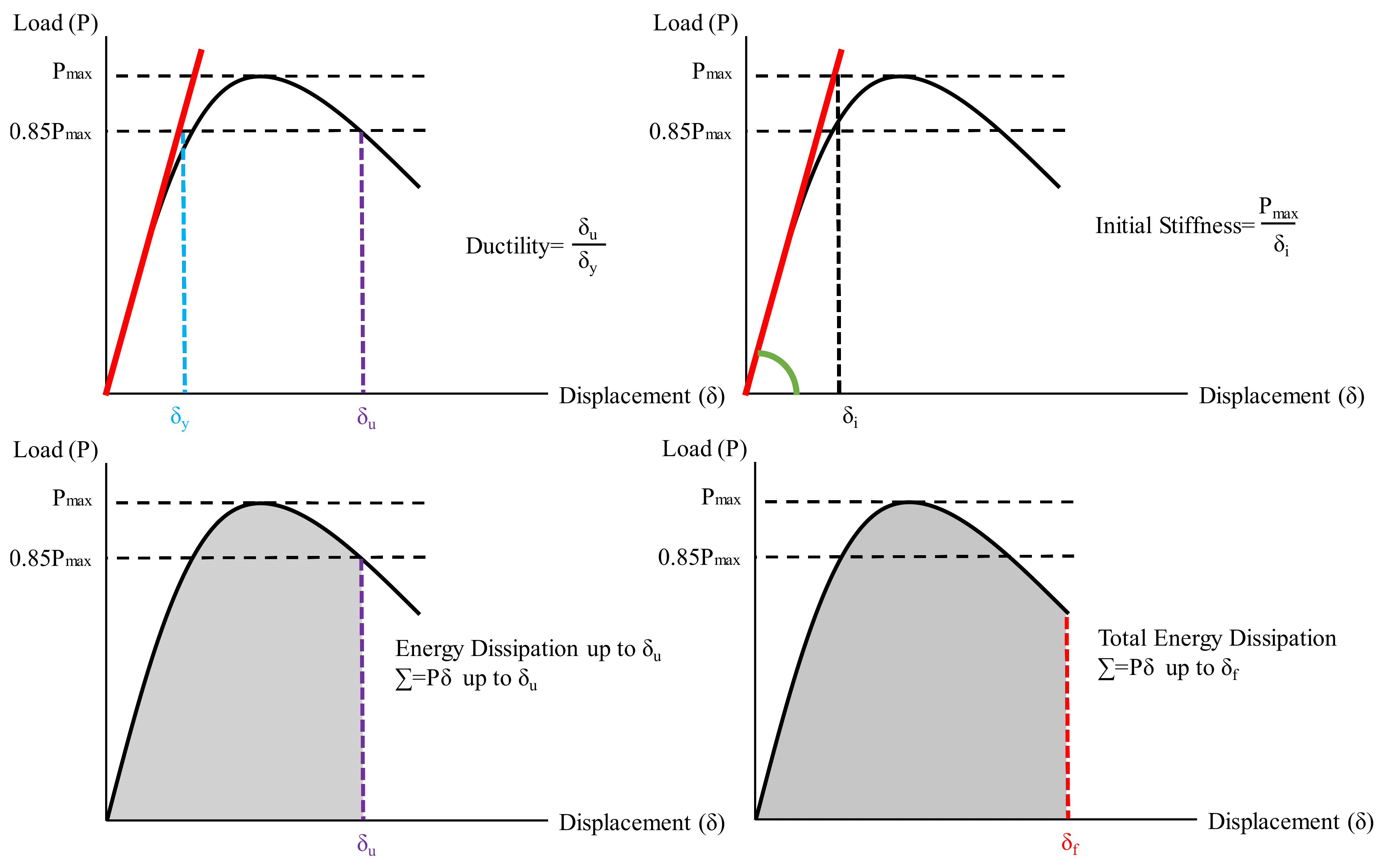
| Test Specimens | Configuration | Initial Stiffness (kN/m) | Max Load (kN) | Ductility Ratio (δu/δy) | Energy Dissipation Capacity up to δu (kN·mm) | Total Energy Dissipation Capacity (kN·mm) |
|---|---|---|---|---|---|---|
| SP1 |  | 8.3 | 81.8 | 1.38 | 478 | 1049 |
| SP2 |  | 9.6 | 85.3 | 1.59 | 643 | 1173 |
| SP3 |  | 11.1 | 101.4 | 2.13 | 1077 | 1303 |
| SP4 |  | 12.3 | 134.5 | 2.26 | 1729 | 2139 |
| SP5 |  | 15.6 | 80.2 | 1.69 | 352 | 838 |
| SP6 |  | 22.5 | 113.1 | 3.25 | 1518 | 1570 |
| SP7 |  | 25.8 | 141.4 | 3.08 | 1773 | 1831 |
| Test Specimens | Damage Modes | Explanation |
|---|---|---|
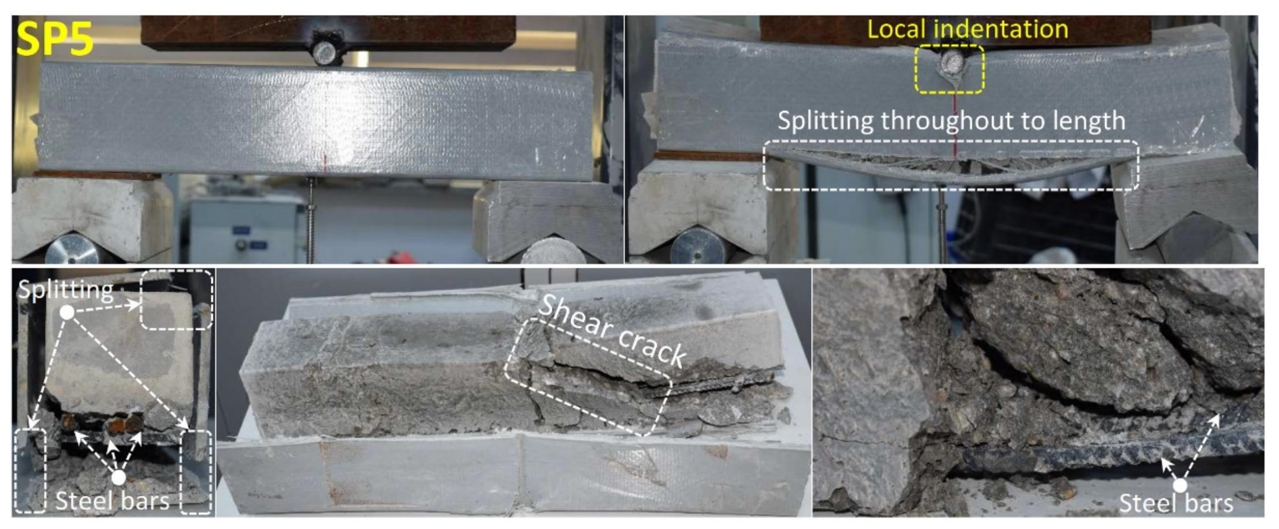
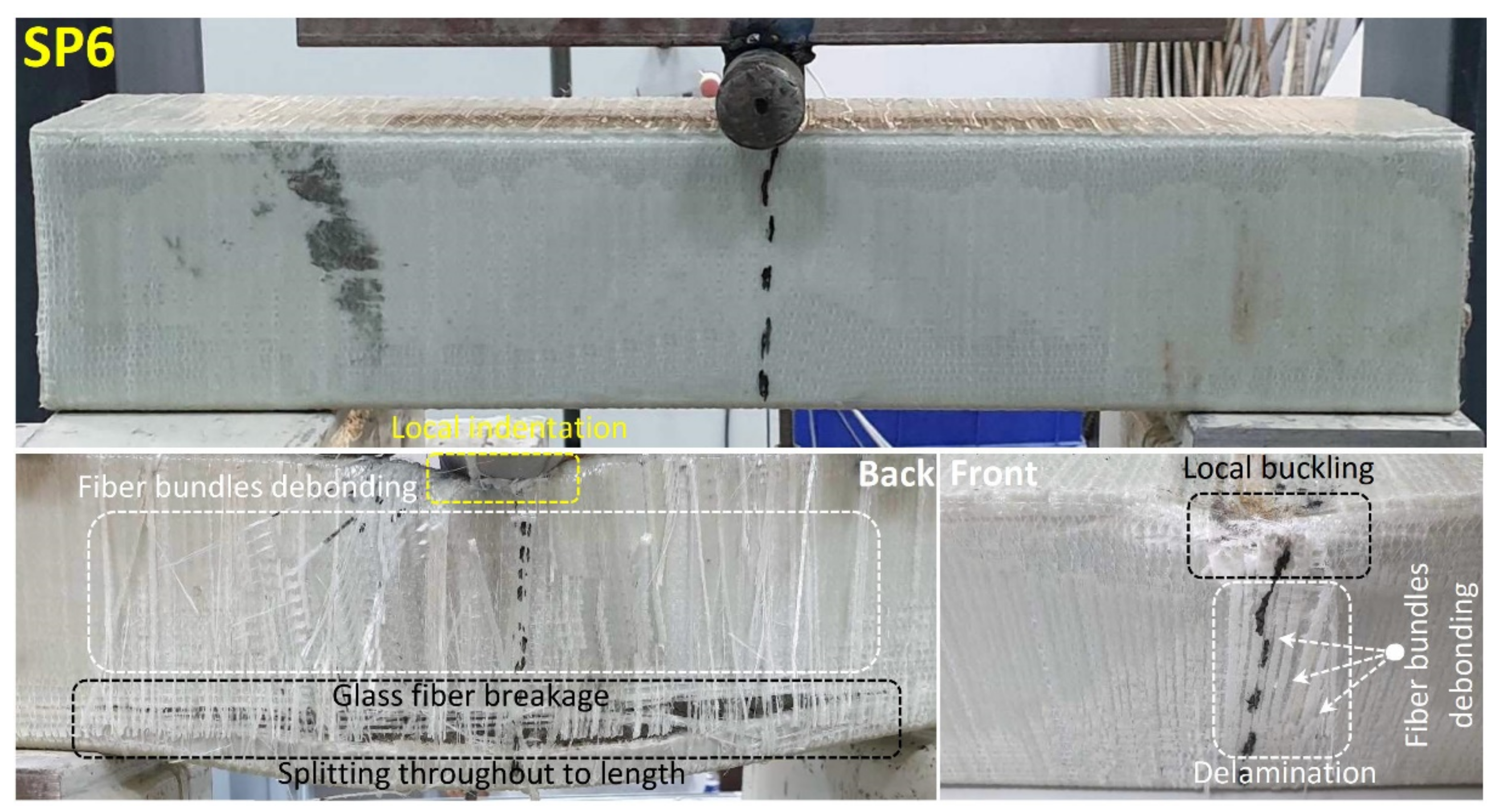
SP1 | - Splitting - Shear cracks | Splitting: It is a type of matrix cracking in the direction of the fiber and parallel to the direction of the applied load. Shear cracks: Shear damage occurred in the concrete Intralaminar splitting: It is longitudinal cleavage damage that occurs in the fiber direction in pultruded GFRP. Buckling damage: It is the damage that occurs under the compression zones in hybrid beams. They are locally pultruded GFRP-based buckling damages. They are the kinkband formed inside the laminate when considered in micro dimension. Local indentation: It is the damage caused by penetrating the composite material in the force region applied by the indentor to the material in four and three point bending tests. Delamination: It is the layer separation between the pultruded CFRP reinforced in different directions and the fiber wrapping application. Fiber breakage: It is the fiber breakage caused by the cleavage damage of the applied CFRP and GFRP fiber wrappings at the corners of the Pultruted GFRPs. Debonding: It is the fiber matrix interface damage that occurs in the direction of reinforcement under load in CFRP and GFRP fiber wrappings. Matrix cracks: In CFRP and GFRP fiber wrapping applications, it is the matrix damage that occurs between the fiber bundles due to the displacement in the beam under load. Fiber bundle breakage: It is the damage of longitudinal bundle breaking of fibers after matrix cracking and debonding damages in fiber wrapping applications. Fiber bundle debonding: It is the damage caused by the progression of matrix cracks during loading in fiber wrapping applications and the separation of fiber bundles from each other. Concrete pull-out: It is formed between pultruded CFRP and concrete. It is the protrusion of the concrete at the beam ends with the effect of shear damage and displacement increase in the concrete. |
SP2 | - Splitting - Intralaminar splitting - Buckling damage - Local indentation - Delamination - Fiber breakage | |
SP3 | - Splitting - Intralaminar splitting - Buckling damage - Local indentation - Delamination - Fiber breakage - Debonding | |
SP4 | - Splitting - Matrix cracks - Fiber bundle breakage - Fiber bundle debonding - Delamination - Local indentation | |
SP5 | - Splitting - Shear cracks - Local indentation | |
SP6 | - Local buckling - Fiber bundle delamination - Delamination - Fiber breakage | |
SP7 | - Splitting - Matrix cracks - Fiber bundle breakage - Concrete pull-out |
Publisher’s Note: MDPI stays neutral with regard to jurisdictional claims in published maps and institutional affiliations. |
© 2022 by the authors. Licensee MDPI, Basel, Switzerland. This article is an open access article distributed under the terms and conditions of the Creative Commons Attribution (CC BY) license (https://creativecommons.org/licenses/by/4.0/).
Share and Cite
Gemi, L.; Madenci, E.; Özkılıç, Y.O.; Yazman, Ş.; Safonov, A. Effect of Fiber Wrapping on Bending Behavior of Reinforced Concrete Filled Pultruded GFRP Composite Hybrid Beams. Polymers 2022, 14, 3740. https://doi.org/10.3390/polym14183740
Gemi L, Madenci E, Özkılıç YO, Yazman Ş, Safonov A. Effect of Fiber Wrapping on Bending Behavior of Reinforced Concrete Filled Pultruded GFRP Composite Hybrid Beams. Polymers. 2022; 14(18):3740. https://doi.org/10.3390/polym14183740
Chicago/Turabian StyleGemi, Lokman, Emrah Madenci, Yasin Onuralp Özkılıç, Şakir Yazman, and Alexander Safonov. 2022. "Effect of Fiber Wrapping on Bending Behavior of Reinforced Concrete Filled Pultruded GFRP Composite Hybrid Beams" Polymers 14, no. 18: 3740. https://doi.org/10.3390/polym14183740