
Fabrication of Electrospun Xylan-g-PMMA/TiO2 Nanofibers and Photocatalytic Degradation of Methylene Blue

 ,
,
Abstract
:1. Introduction
2. Materials and Methods
2.1. Materials and Chemicals
2.2. Synthesis of Xylan-g-PMMA
2.3. Viscosity Measurement and Structural Characterizations
2.4. Electrospinning
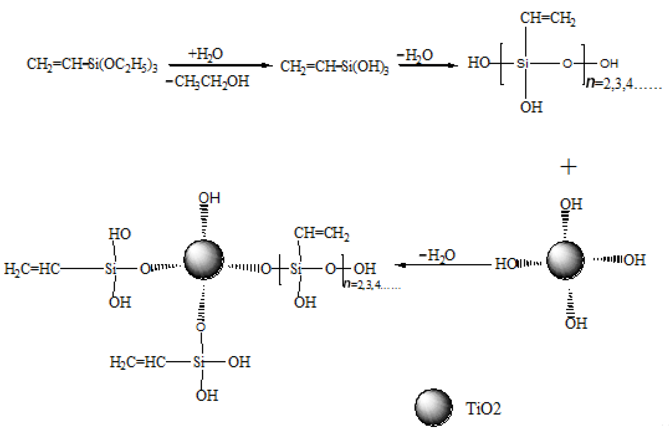
2.5. The Preparation of Electrospun Xylan-g-PMMA/TiO2 Fibers
2.6. Photocatalytic Degradation Property of Electrospun Xylan-g-PMMA/TiO2 Fibers
3. Results
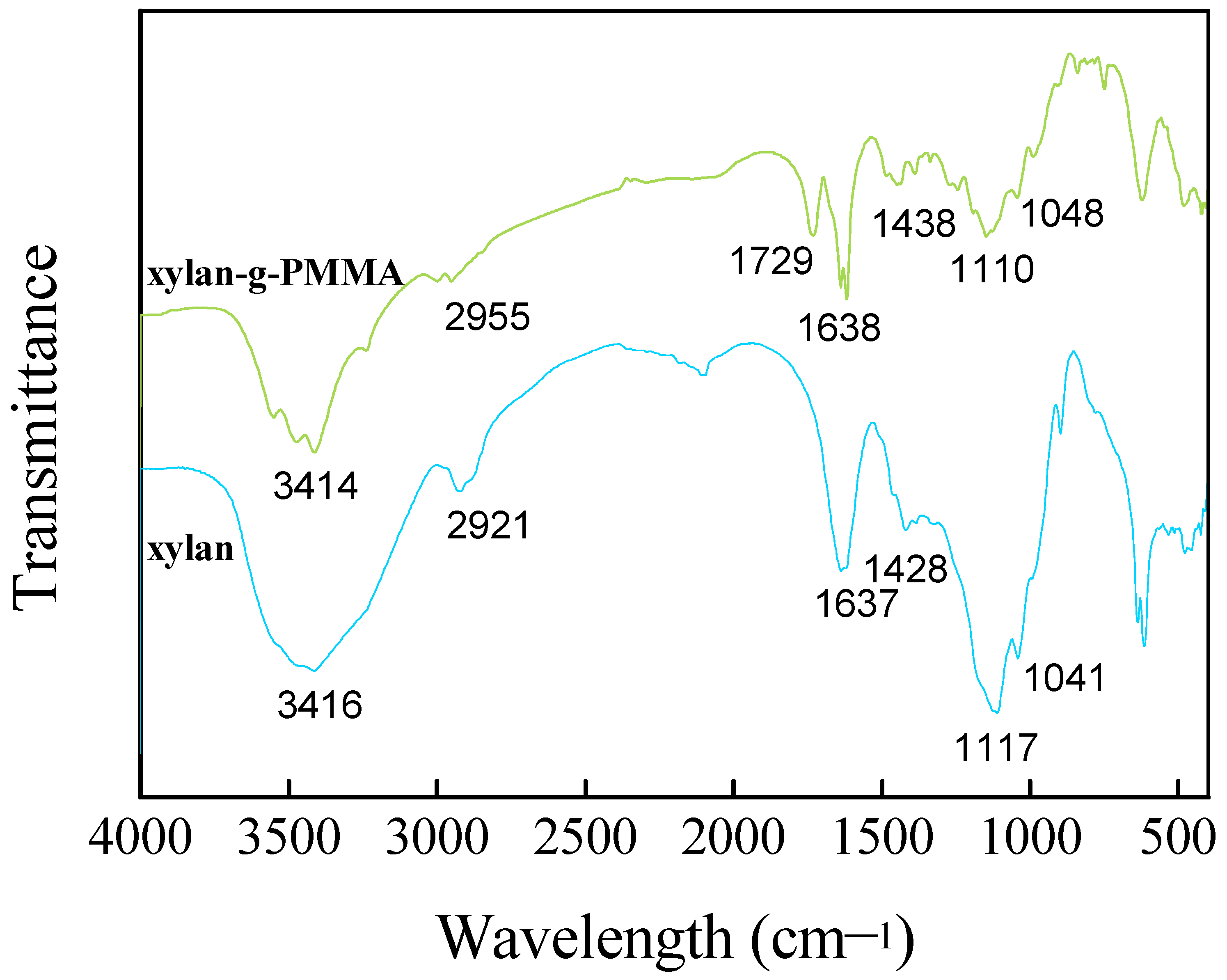
3.1. FT-IR Analysis
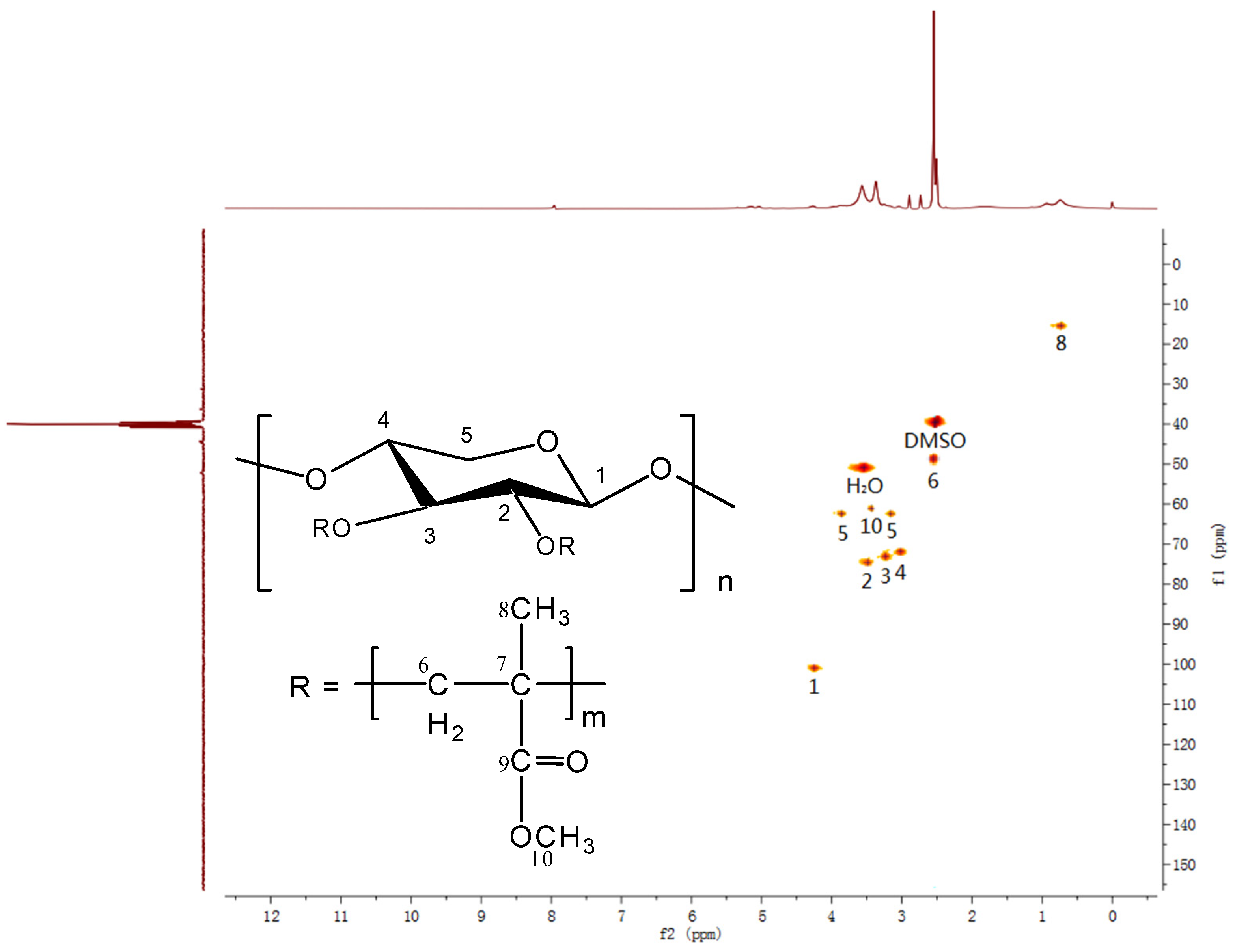
3.2. NMR Analysis
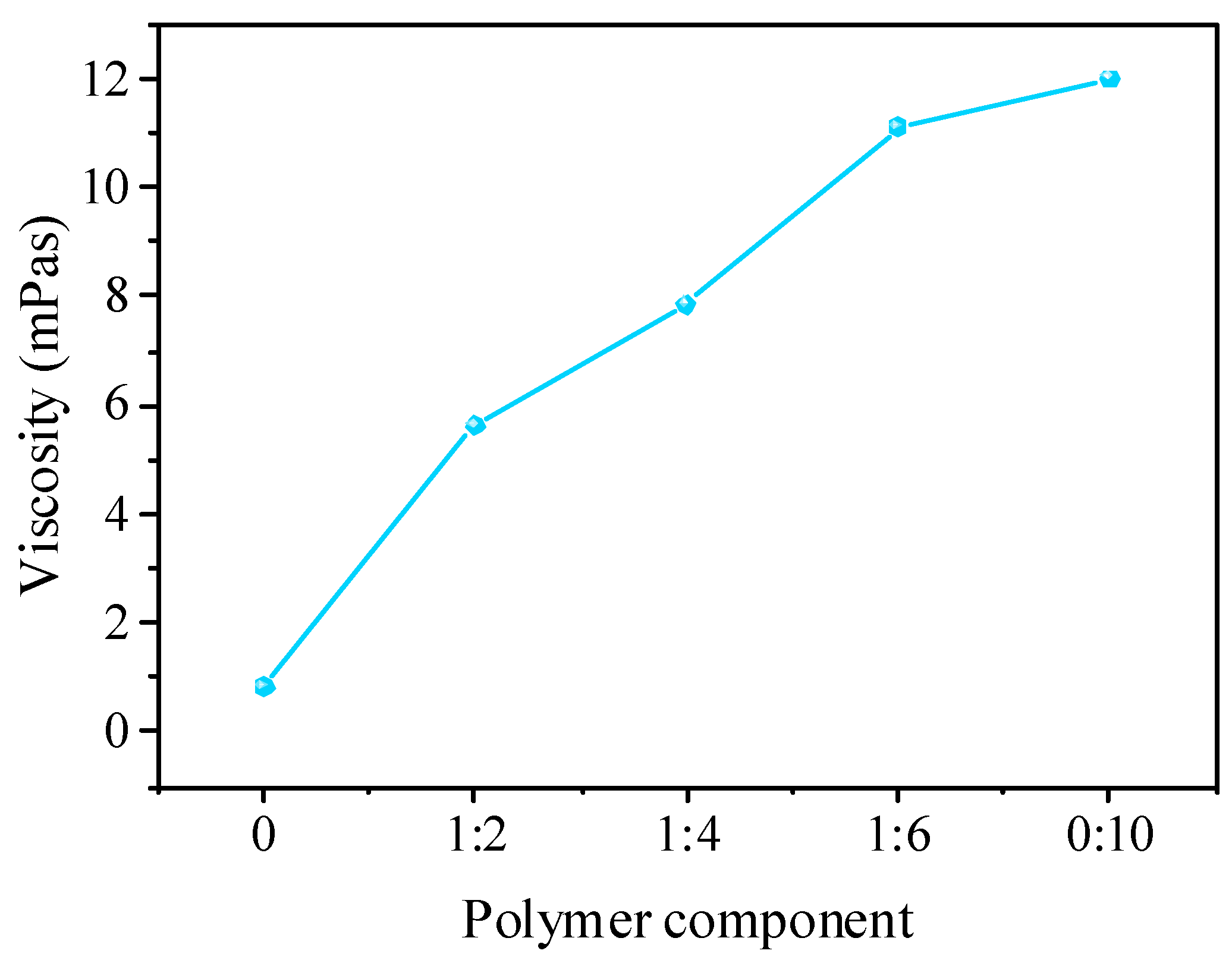
3.3. Polymer Solution Viscosity
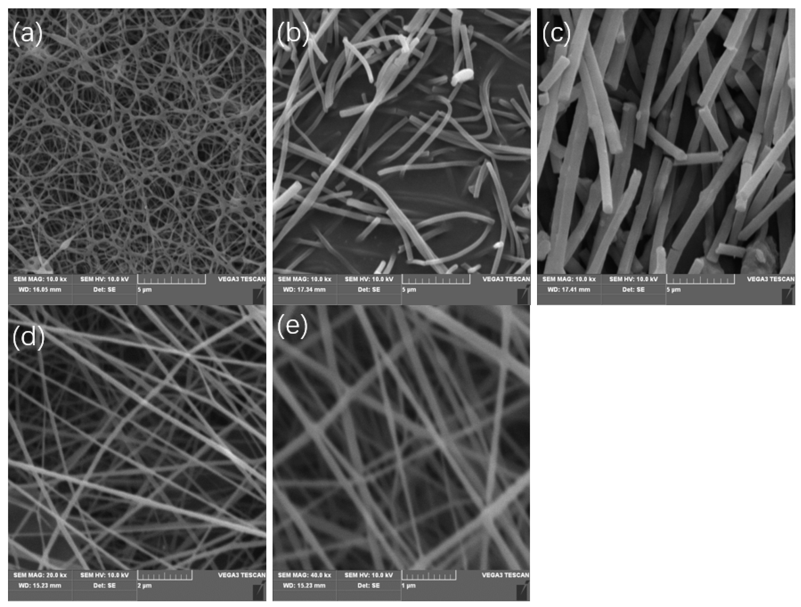
3.4. Effect of Solvents on Electrospinning
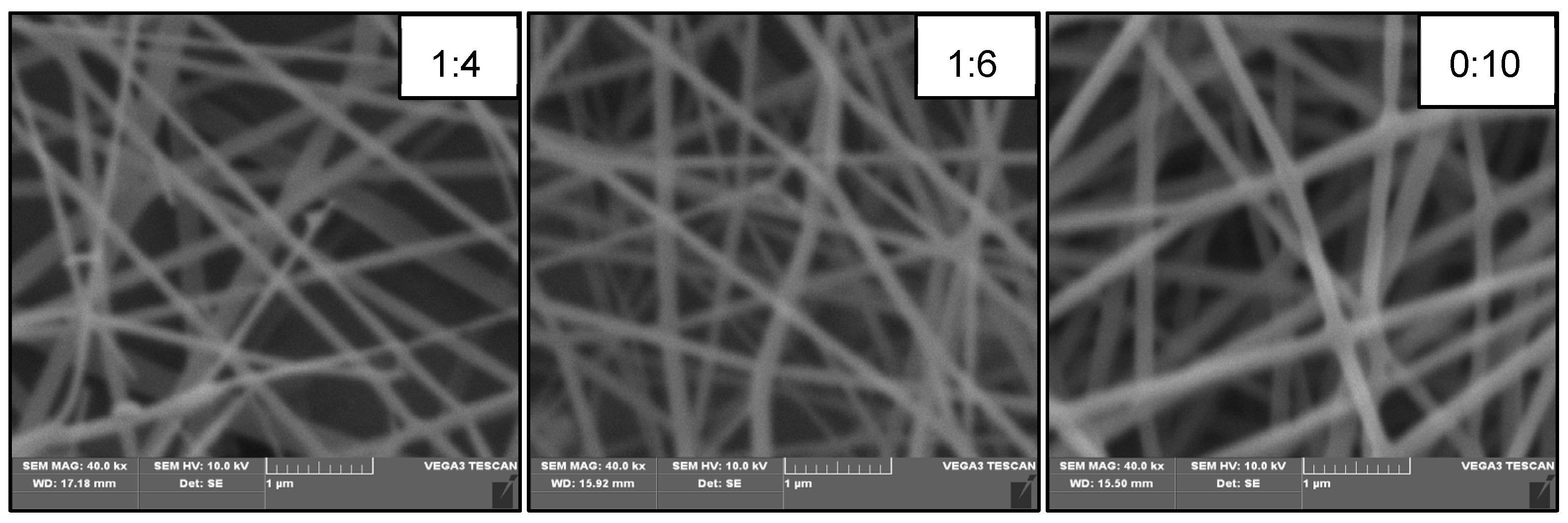
3.5. Effect of AXU/MMA Molar Ratio on Electrospinning
3.6. Effect of Flow Speed on Electrospinning
3.7. Effect of Receiving Distance on Electrospinning
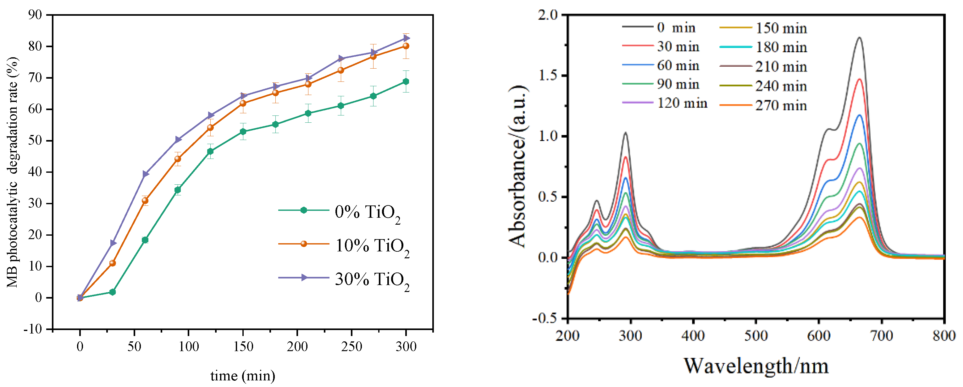
3.8. Photocatalytic Degradation of MB by Electrospun Xylan-g-PMMA/TiO2 Fibers
4. Conclusions
Author Contributions
Funding
Institutional Review Board Statement
Informed Consent Statement
Data Availability Statement
Conflicts of Interest
References
- Bhardwaj, N.; Kundu, S.C. Electrospinning: A fascinating fiber fabrication technique. Biotechnol. Adv. 2010, 28, 325–347. [Google Scholar] [CrossRef] [PubMed]
- Rahmati, M.; Mills, D.K.; Urbanska, A.M.; Saeb, M.R.; Venugopal, J.R.; Ramakrishna, S.; Mozafari, M. Electrospinning for tissue engineering applications. Prog. Mater. Sci. 2021, 117, 100721. [Google Scholar] [CrossRef]
- Zeleny, J. The electrical discharge from liquid points, and a hydrostatic method of measuring the electric intensity at their surfaces. Phys. Rev. 1914, 3, 69–91. [Google Scholar] [CrossRef] [Green Version]
- Formahls, A. Process and Apparatus for Preparing Artificial Threds. U.S. Patent 1975504, 10 February 1934. [Google Scholar]
- Taylor, G. Electrically Driven Jets. Proc. R. Soc. Lon. Ser.-A 1969, 313, 453–475. [Google Scholar]
- Xue, J.; Wu, T.; Dai, Y.; Xia, Y. Electrospinning and electrospun nanofibers: Methods, materials, and applications. Chem. Rev. 2019, 119, 5298–5415. [Google Scholar] [CrossRef]
- Ognibene, G.; Gangemi, C.M.A.; Spitaleri, L.; Gulino, A.; Purrello, R.; Cicala, G.; Fragala, M.E. Role of the surface composition of the polyethersulfone-TiiP-H2T4 fibers on lead removal: From electrostatic to coordinative binding. J. Mater. Sci. 2019, 54, 8023–8033. [Google Scholar] [CrossRef]
- Yoon, J.; Yang, H.S.; Lee, B.S.; Yu, W.R. Recent progress in coaxial electrospinning: New parameters, various structures, and wide applications. Adv. Mater. 2018, 30, 1704765. [Google Scholar] [CrossRef]
- Avossa, J.; Herwig, G.; Toncelli, C.; Itel, F.; Rossi, R.M. Electrospinning based on benign solvents: Current definitions, implications and strategies. Green Chem. 2022, 24, 2347–2375. [Google Scholar] [CrossRef]
- Bombin, A.D.J.; Dunne, N.J.; McCarthy, H.O. Electrospinning of natural polymers for the production of nanofibres for wound healing applications. Mater. Sci. Eng. C 2020, 114, 110994. [Google Scholar] [CrossRef]
- Pakravan, M.; Heuzey, M.C.; Ajji, A. Core-shell structured PEO-chitosan nanofibers by coaxial electrospinning. Biomacromolecules 2012, 13, 412–421. [Google Scholar] [CrossRef]
- Jing, Z.; Xu, X.Y.; Chen, X.S.; Liang, Q.Z.; Bian, X.C.; Yang, L.X.; Jing, X.B. Biodegradable electrospun fibers for drug delivery. J. Control. Release 2003, 92, 227–231. [Google Scholar]
- Zhou, H.J.; Green, T.B.; Joo, Y.L. The thermal effects on electrospinning of polylactic acid melts. Polymer 2006, 47, 7497–7505. [Google Scholar] [CrossRef]
- Kim, C.; Park, S.H.; Cho, J.K.; Lee, D.Y.; Park, T.J.; Lee, W.J.; Yang, K.S. Raman spectroscopic evaluation of polyacrylonitrile-based carbon nanofibers prepared by electrospinning. J. Raman Spectrosc. 2004, 35, 928–933. [Google Scholar] [CrossRef]
- Nirmala, R.; Navamathavan, R.; Park, S.J.; Kim, H.Y. Recent Progress on the Fabrication of Ultrafine Polyamide-6 Based Nanofibers Via Electro- spinning: A Topical Review. Nano-Micro Lett. 2014, 6, 19. [Google Scholar] [CrossRef]
- Reneker, D.H.; Kataphinan, W.; Theron, A.; Zussman, E.; Yarin, A.L. Nanofiber garlands of polycaprolactone by electrospinning. Polymer 2002, 43, 6785–6794. [Google Scholar] [CrossRef]
- Acarer, S.; Pir, I.; Tufekci, M.; Turkoglu Demirkol, G.; Tufekci, N. Manufacturing and characterisation of polymeric membranes for water treatment and numerical investigation of mechanics of nanocomposite membranes. Polymers 2021, 13, 1661. [Google Scholar] [CrossRef]
- Zheng, J.F.; He, A.H.; Li, J.X.; Han, C.C. Polymorphism control of poly(vinylidene fluoride) through electrospinning. Macromol. Rapid Commun. 2007, 28, 2159–2162. [Google Scholar] [CrossRef]
- Gangemi, C.M.A.; Iudici, M.; Spitaleri, L.; Randazzo, R.; Gaeta, M.; D’Urso, A.; Gulino, A.; Purrello, R.; Fragala, M.E. Polyethersulfone mats functionalized with porphyrin for removal of para-nitroaniline from aqueous solution. Molecules 2019, 24, 3344. [Google Scholar] [CrossRef] [Green Version]
- Boland, E.D.; Matthews, J.A.; Pawlowski, K.J.; Simpson, D.G.; Wnek, G.E.; Bowlin, G.L. Electrospinning collagen and elastin: Preliminary vascular tissue engineering. Front. Biosci. 2004, 9, 1422–1432. [Google Scholar] [CrossRef] [Green Version]
- Geng, X.Y.; Kwon, O.H.; Jang, J.H. Electrospinning of chitosan dissolved in concentrated acetic acid solution. Biomaterials 2005, 26, 5427–5432. [Google Scholar] [CrossRef]
- Xu, S.S.; Zhang, J.; He, A.H.; Li, J.X.; Zhang, H.; Han, C.C. Electrospinning of native cellulose from nonvolatile solvent system. Polymer 2008, 49, 2911–2917. [Google Scholar] [CrossRef]
- Pascu, E.I.; Stokes, J.; McGuinness, G.B. Electrospun composites of PHBV, silk fibroin and nano-hydroxyapatite for bone tissue engineering. Mat. Sci. Eng. C-Mater. 2013, 33, 4905–4916. [Google Scholar] [CrossRef] [PubMed]
- Devadas, S.; Al-Ajrash, S.M.N.; Klosterman, D.A.; Crosson, K.M.; Crosson, G.S.; Vasquez, E.S. Fabrication and characterization of electrospun poly(acrylonitrile-co-methyl acrylate)/lignin nanofibers: Effects of lignin type and total polymer concentration. Polymers 2021, 13, 992. [Google Scholar] [CrossRef] [PubMed]
- Shi, S.; Si, Y.; Han, Y.; Wu, T.; Iqbal, M.I.; Fei, B.; Li, R.K.; Hu, J.; Qu, J. Recent progress in protective membranes fabricated via electrospinning: Advanced materials, biomimetic structures, and functional applications. Adv. Mater. 2021, 34, 2107938. [Google Scholar] [CrossRef] [PubMed]
- Soares, R.M.D.; Siqueira, N.M.; Prabhakaram, M.P.; Ramakrishna, S. Electrospinning and electrospray of bio-based and natural polymers for biomaterials development. Mater. Sci. Eng. C Mater. Biol. Appl. 2018, 92, 969–982. [Google Scholar] [CrossRef]
- Wang, F.D.; Hu, S.; Jia, Q.X.; Zhang, L.Q. Advances in electrospinning of natural biomaterials for wound dressing. J. Nanomater. 2020, 2020, 8719859. [Google Scholar] [CrossRef] [Green Version]
- Rostamabadi, H.; Assadpour, E.; Tabarestani, H.S.; Falsafi, S.R.; Jafari, S.M. Electrospinning approach for nanoencapsulation of bioactive compounds; recent advances and innovations. Trends Food Sci. Technol. 2020, 100, 190–209. [Google Scholar] [CrossRef]
- Cunha, A.G.; Gandini, A. Turning polysaccharides into hydrophobic materials: A critical review. Part 1. Cellulose. Cellulose 2010, 17, 875–889. [Google Scholar] [CrossRef]
- Sun, X.F.; Zhang, T.; Wang, H.H. Hemicelluloses-based hydrogels. In Plant and Algal Hydrogels for Drug Delivery and Regenerative Medicine; Giri, T.K., Ghosh, B., Eds.; Woodhead Publishing: Sawston, UK, 2021; pp. 181–216. [Google Scholar]
- Luo, Y.P.; Li, Z.; Li, X.L.; Liu, X.F.; Fan, J.J.; Clark, J.H.; Hu, C.W. The production of furfural directly from hemicellulose in lignocellulosic biomass: A review. Catal. Today 2019, 319, 14–24. [Google Scholar] [CrossRef]
- Berglund, J.; Mikkelsen, D.; Flanagan, B.M.; Dhital, S.; Gaunitz, S.; Henriksson, G.; Lindstrom, M.E.; Yakubov, G.E.; Gidley, M.J.; Vilaplana, F. Wood hemicelluloses exert distinct biomechanical contributions to cellulose fibrillar networks. Nat. Commun. 2020, 11, 4692. [Google Scholar] [CrossRef]
- Sun, X.F.; Sun, R.C.; Fowler, P.; Baird, M.S. Extraction and characterization of original lignin and hemicelluloses from wheat straw. J. Agric. Food Chem. 2005, 53, 860–870. [Google Scholar] [CrossRef] [PubMed]
- da Silva, A.E.; Marcelino, H.R.; Gomes, M.C.S.; Oliveira, E.E.; Nagashima, T., Jr.; Egito, E.S.T. Xylan, a promising hemicellulose for pharmaceutical use. In Products and Applications of Biopolymers; Verbeek, C.J.R., Ed.; InTechOpen: Londdon, UK, 2012; pp. 61–84. ISBN 978-953-51-0226-7. [Google Scholar]
- Naidu, D.S.; Hlangothi, S.P.; John, M.J. Bio-based products from xylan: A review. Carbohydr. Polym. 2018, 179, 28–41. [Google Scholar] [CrossRef] [PubMed]
- Petzold-Welcke, K.; Schwikal, K.; Daus, S.; Heinze, T. Xylan derivatives and their application potential—Mini-review of own results. Carbohydr. Polym. 2014, 100, 80–88. [Google Scholar] [CrossRef] [PubMed]
- Grondahl, M.; Eriksson, L.; Gatenholm, P. Material properties of plasticized hardwood xylans for potential application as oxygen barrier films. Biomacromolecules 2004, 5, 1528–1535. [Google Scholar] [CrossRef]
- Moure, A.; Gullon, P.; Dominguez, H.; Parajo, J.C. Advances in the manufacture, purification and applications of xylo-oligosaccharides as food additives and nutraceuticals. Process Biochem. 2006, 41, 1913–1923. [Google Scholar] [CrossRef]
- Fu, C.L.; Dong, X.B.; Wang, S.J.; Kong, F.G. Synthesis of nanocomposites using xylan and graphite oxide for remediation of cationic dyes in aqueous solutions. Int. J. Biol. Macromol. 2019, 137, 886–894. [Google Scholar] [CrossRef]
- Kamdem, D.P.; Shen, Z.; Nabinejad, O.; Shu, Z.J. Development of biodegradable composite chitosan-based films incorporated with xylan and carvacrol for food packaging application. Food Packag. Shelf Life 2019, 21, 100344. [Google Scholar] [CrossRef]
- Rao, J.; Lv, Z.; Chen, G.; Hao, X.; Guan, Y.; Peng, F. Fabrication of flexible composite film based on xylan from pulping process for packaging application. Int. J. Biol. Macromol. 2021, 173, 285–292. [Google Scholar] [CrossRef]
- Sauraj; Kumar, S.U.; Kumar, V.; Priyadarshi, R.; Gopinath, P.; Negi, Y.S. pH-responsive prodrug nanoparticles based on xylan-curcumin conjugate for the efficient delivery of curcumin in cancer therapy. Carbohyd. Polym. 2018, 188, 252–259. [Google Scholar] [CrossRef]
- Ali, A.; Hasan, A.; Negi, Y.S. Effect of cellulose nanocrystals on xylan/chitosan/nanoβ-TCP composite matrix for bone tissue engineering. Cellulose 2022, 29, 5689–5709. [Google Scholar] [CrossRef]
- Wu, J.; Wang, N.; Zhao, Y.; Jiang, L. Electrospinning of multilevel structured functional micro-/nanofibers and their applications. J. Mater. Chem. A 2013, 1, 7290–7305. [Google Scholar] [CrossRef]
- Baji, A.; Mai, Y.W.; Wong, S.C.; Abtahi, M.; Chen, P. Electrospinning of polymer nanofibers: Effects on oriented morphology, structures and tensile properties. Compos. Sci. Technol. 2010, 70, 703–718. [Google Scholar] [CrossRef]
- Zhang, C.Q.; Lu, R.H.; Liu, C.; Yuan, L.; Wang, J.; Zhao, Y.; Yu, C.Z. High yield electrosynthesis of hydrogen peroxide from water using electrospun CaSnO3@carbon fiber membrane catalysts with abundant oxygen vacancy. Adv. Funct. Mater. 2021, 31, 2100099. [Google Scholar] [CrossRef]
- Li, S.; Cui, Z.M.; Li, D.M.; Yue, G.C.; Liu, J.; Ding, H.G.; Gao, S.W.; Zhao, Y.C.; Wang, N.; Zhao, Y. Hierarchically structured electrospinning nanofibers for catalysis and energy storage. Compos. Commun. 2019, 13, 1–11. [Google Scholar] [CrossRef]
- Lu, T.; Cui, J.; Qu, Q.; Wang, Y.; Zhang, J.; Xiong, R.; Ma, W.; Huang, C. Multistructured electrospun nanofibers for air filtration: A review. ACS Appl. Mater. Interfaces 2021, 13, 23293–23313. [Google Scholar] [CrossRef]
- Deng, Y.K.; Lu, T.; Cui, J.X.; Samal, S.K.; Xiong, R.H.; Huang, C.B. Bio-based electrospun nanofiber as building blocks for a novel eco-friendly air filtration membrane: A review. Sep. Purif. Technol. 2021, 277, 119623. [Google Scholar] [CrossRef]
- Khoshnevisan, K.; Maleki, H.; Samadian, H.; Shahsavari, S.; Sarrafzadeh, M.H.; Larijani, B.; Dorkoosh, F.A.; Haghpanah, V.; Khorramizadeh, M.R. Cellulose acetate electrospun nanofibers for drug delivery systems: Applications and recent advances. Carbohydr. Polym. 2018, 198, 131–141. [Google Scholar] [CrossRef]
- Wu, J.; Zhang, Z.; Gu, J.; Zhou, W.; Liang, X.; Zhou, G.; Han, C.C.; Xu, S.; Liu, Y. Mechanism of a long-term controlled drug release system based on simple blended electrospun fibers. J. Control. Release 2020, 320, 337–346. [Google Scholar] [CrossRef]
- Abutaleb, A. Catalytic and photocatalytic electrospun nanofibers for hydrogen generation from ammonia borane complex: A review. Polymers 2021, 13, 2290. [Google Scholar] [CrossRef]
- Salmeri, M.; Ognibene, G.; Saitta, L.; Lombardo, C.; Genovese, C.; Barcellona, M.; D’Urso, A.; Spitaleri, L.; Blanco, I.; Cicala, G.; et al. Optimization of ZnO nanorods growth on polyetheresulfone electrospun mats to promote antibacterial properties. Molecules 2020, 25, 1696. [Google Scholar] [CrossRef] [Green Version]
- Xiao, B.Q.; Wang, W.; Zhang, X.; Long, G.B.; Fan, J.T.; Chen, H.X.; Deng, L. A novel fractal solution for permeability and Kozeny-Carman constant of fibrous porous media made up of solid particles and porous fibers. Powder Technol. 2019, 349, 92–98. [Google Scholar] [CrossRef]
- Gunn, D.J. Transfer of heat or mass to particles in fixed and fluidized-beds. Int. J. Heat Mass Transfer 1978, 21, 467–476. [Google Scholar] [CrossRef]
- Boudart, M. Catalysis by supported metals. Adv. Catal. 1969, 20, 153–166. [Google Scholar]
- Navalón, S.; Herance, J.R.; Álvaro, M.; García, H. General aspects in the use of graphenes in catalysis. Mater. Horiz. 2018, 5, 363–378. [Google Scholar] [CrossRef]
- Formo, E.; Lee, E.; Campbell, D.; Xia, Y. Functionalization of electrospun TiO2 nanofibers with Pt nanoparticles and nanowires for catalytic applications. Nano Lett. 2008, 8, 668–672. [Google Scholar] [CrossRef] [PubMed]
- Patel, A.C.; Li, S.X.; Wang, C.; Zhang, W.J.; Wei, Y. Electrospinning of porous silica nanofibers containing silver nanoparticles for catalytic applications. Chem. Mater. 2007, 19, 1231–1238. [Google Scholar] [CrossRef]
- Guo, Q.; Zhou, C.; Ma, Z.; Yang, X. Fundamentals of TiO2 photocatalysis: Concepts, mechanisms, and challenges. Adv. Mater. 2019, 31, e1901997. [Google Scholar] [CrossRef]
- Meng, A.; Zhang, L.; Cheng, B.; Yu, J. Dual cocatalysts in TiO2 photocatalysis. Adv. Mater. 2019, 31, e1807660. [Google Scholar] [CrossRef]
- Ruan, X.; Cui, X.; Cui, Y.; Fan, X.; Li, Z.; Xie, T.; Ba, K.; Jia, G.; Zhang, H.; Zhang, L. Favorable energy band alignment of TiO2 anatase/rutile heterophase homojunctions yields photocatalytic hydrogen evolution with quantum efficiency exceeding 45.6%. Adv. Energy Mater. 2022, 12, 2200298. [Google Scholar] [CrossRef]
- Shayegan, Z.; Lee, C.S.; Haghighat, F. TiO2 photocatalyst for removal of volatile organic compounds in gas phase—A review. Chem. Eng. J. 2018, 334, 2408–2439. [Google Scholar] [CrossRef] [Green Version]
- Zimbone, M.; Cacciato, G.; Spitaleri, L.; Egdell, R.G.; Grimaldi, M.G.; Gulino, A. Sb-doped titanium oxide: A rationale for its photocatalytic activity for environmental remediation. ACS Omega 2018, 3, 11270–11277. [Google Scholar] [CrossRef] [PubMed] [Green Version]
- Naldoni, A.; Altomare, M.; Zoppellaro, G.; Liu, N.; Kment, S.; Zboril, R.; Schmuki, P. Photocatalysis with reduced TiO2: From black TiO2 to cocatalyst-free hydrogen production. ACS Catal. 2019, 9, 345–364. [Google Scholar] [CrossRef] [PubMed] [Green Version]
- Kumaravel, V.; Mathew, S.; Bartlett, J.; Pillai, S.C. Photocatalytic hydrogen production using metal doped TiO2: A review of recent advances. Appl. Catal. B 2019, 244, 1021–1064. [Google Scholar] [CrossRef]
- Fang, S.; Liu, Y.; Sun, Z.; Lang, J.; Bao, C.; Hu, Y.H. Photocatalytic hydrogen production over Rh-loaded TiO2: What is the origin of hydrogen and how to achieve hydrogen production from water? Appl. Catal. B 2020, 278, 119316. [Google Scholar] [CrossRef]
- Kusiak-Nejman, E.; Morawski, A.W. TiO2/graphene-based nanocomposites for water treatment: A brief overview of charge carrier transfer, antimicrobial and photocatalytic performance. Appl. Catal. B 2019, 253, 179–186. [Google Scholar] [CrossRef]
- Yang, X.J.; Sun, H.W.; Li, G.Y.; An, T.C.; Choi, W.Y. Fouling of TiO2 induced by natural organic matters during photocatalytic water treatment: Mechanisms and regeneration strategy. Appl. Catal. B 2021, 294, 120252. [Google Scholar] [CrossRef]
- Shehzad, N.; Tahir, M.; Johari, K.; Murugesan, T.; Hussain, M. A critical review on TiO2 based photocatalytic CO2 reduction system: Strategies to improve efficiency. J. CO2 Util. 2018, 26, 98–122. [Google Scholar] [CrossRef]
- Xiong, Z.; Lei, Z.; Li, Y.Z.; Dong, L.C.; Zhao, Y.C.; Zhang, J.Y. A review on modification of facet-engineered TiO2 for photocatalytic CO2 reduction. J. Photochem. Photobiol. C 2018, 36, 24–47. [Google Scholar] [CrossRef]
- Wang, L.B.; Cheng, B.; Zhang, L.Y.; Yu, J.G. In situ irradiated XPS investigation on S-scheme TiO2@ZnIn2S4 photocatalyst for efficient photocatalytic CO2 reduction. Small 2021, 17, 2103447. [Google Scholar] [CrossRef]
- Kaplan, R.; Erjavec, B.; Pintar, A. Enhanced photocatalytic activity of single-phase, nanocomposite and physically mixed TiO2 polymorphs. Appl. Catal. A-Gen. 2015, 489, 51–60. [Google Scholar] [CrossRef]
- Fiorenza, R.; Bellardita, M.; Balsamo, S.A.; Spitaleri, L.; Gulino, A.; Condorelli, M.; D’Urso, L.; Scirè, S.; Palmisano, L. A solar photothermocatalytic approach for the CO2 conversion: Investigation of different synergisms on CoO-CuO/brookite TiO2-CeO2 catalysts. Chem. Eng. J. 2022, 428, 131249. [Google Scholar] [CrossRef]
- Diebold, U. The surface science of titanium dioxide. Surf. Sci. Rep. 2003, 48, 53–229. [Google Scholar] [CrossRef]
- Linsebigler, A.L.; Lu, G.Q.; Yates, J.T. Photocatalysis on TiO2 surfaces—principles, mechanisms, and selected results. Chem. Rev. 1995, 95, 735–758. [Google Scholar] [CrossRef]
- Fujishima, A.; Vitae, T.N.R.; Tryk, D.A. Titanium dioxide photocatalysis. J. Photochem. Photobiol. C Photochem. Rev. 2000, 1, 21. [Google Scholar] [CrossRef]
- Wright, S.L.; Kelly, F.J. Plastic and human health: A micro issue? Environ. Sci. Technol. 2017, 51, 6634–6647. [Google Scholar] [CrossRef] [PubMed]
- Gulino, A.; Papanikolaou, G.; Lanzafame, P.; Aaliti, A.; Primerano, P.; Spitaleri, L.; Triolo, C.; Dahrouch, Z.; Khaskhoussi, A.; Lo Schiavo, S. Synthesis, characterization and photocatalytic behavior of SiO2@nitrized-TiO2 nanocomposites obtained by a straightforward novel approach. Chemistryopen 2021, 10, 1033–1040. [Google Scholar] [CrossRef] [PubMed]
- Sun, R.C.; Fang, J.M.; Goodwin, A.; Lawther, J.M.; Bolton, A.J. Fractionation and characterization of polysaccharides from abaca fibre. Carbohydr. Polym. 1998, 37, 351–359. [Google Scholar] [CrossRef]
- Shan, S.; Sun, X.-F.; Xie, Y.; Li, W.; Ji, T. High-performance hydrogel adsorbent based on cellulose, hemicellulose, and lignin for copper(II) ion removal. Polymers 2021, 13, 3063. [Google Scholar] [CrossRef]
- Delekar, S.D.; Dhodamani, A.G.; More, K.V.; Dongale, T.D.; Kamat, R.K.; Acquah, S.F.A.; Dalal, N.S.; Panda, D.K. Structural and optical properties of nanocrystalline TiO2 with multiwalled carbon nanotubes and its photovoltaic studies using Ru(II) sensitizers. ACS Omega 2018, 3, 2743–2756. [Google Scholar] [CrossRef] [PubMed] [Green Version]
- Fiorenza, R.; Di Mauro, A.; Cantarella, M.; Iaria, C.; Scalisi, E.M.; Brundo, M.V.; Gulino, A.; Spitaleri, L.; Nicotra, G.; Dattilo, S.; et al. Preferential removal of pesticides from water by molecular imprinting on TiO2 photocatalysts. Chem. Eng. J. 2020, 379, 122309. [Google Scholar] [CrossRef]
- Brar, A.S.; Singh, G.; Shankar, R. Structural investigations of poly(methyl methacrylate) by two-dimensional NMR. J. Mol. Struct. 2004, 703, 69–81. [Google Scholar] [CrossRef]
- Sun, X.-F.; Xie, Y.; Shan, S.; Li, W.; Sun, L. Chemically-crosslinked xylan/graphene oxide composite hydrogel for copper ions removal. J. Polym. Environ. 2022; in press. [Google Scholar] [CrossRef]
- Gan, Z.; Sun, X.F.; Ye, Q.; Li, Y.J.; Zhang, L.; Liu, B.C. The preparation and electrospinning of hemicellulose-grafted-poly (acrylic acid). New Chem. Mater. 2013, 41, 158–160+183. (In Chinese) [Google Scholar]
- Gulino, A.; Condorelli, G.G.; Mineo, P.; Fragalà, I. An x-ray photoelectron spectra and atomic force microscopy characterization of silica substrates engineered with a covalently assembled siloxane monolayer. Nanotechnology 2005, 16, 2170–2175. [Google Scholar] [CrossRef] [PubMed]
- Contino, A.; Maccarrone, G.; Fragalà, M.E.; Spitaleri, L.; Gulino, A. Conjugated gold–porphyrin monolayers assembled on inorganic surfaces. Chem.–Eur. J. 2017, 23, 14937–14943. [Google Scholar] [CrossRef] [PubMed]


| Molar Ratio of Xylan/MMA | Flow Speed/(mL/min) | Receiving Distance/cm | Solvents | Diameters of the Fibers/nm | ||
|---|---|---|---|---|---|---|
| Max. | Min. | Mean | ||||
| 1:4 | 0.05650 | 15 | 5 mL DMF + 1 mL acetone (c) | 1184.83 | 596.61 | 744.52 |
| 5 mL DMF + 2 mL acetone (b) | 435.57 | 150.35 | 297.82 | |||
| 1:4 | 0.01130 | 10 | 5 mL DMF + 1 mL chloroform(e) | 160.83 | 66.28 | 140.37 |
| 5 mL DMF + 1 mL chloroform + 1 acetone (d) | 130.82 | 63.05 | 99.41 | |||
| 1:6 | 0.00565 | 15 | 5 mL DMF + 1 mL chloroform | 253.35 | 88.88 | 164.2 |
| 5 mL DMF + 1 mL chloroform + 1 mL acetone | 209.27 | 88.92 | 137.41 | |||
| Molar Ratio of Xylan/MMA | Solvent | Receiving Distance/cm | Flow Speed/(mL/min) | Diameters of the Fibers/nm | ||
|---|---|---|---|---|---|---|
| Max. | Min. | Mean | ||||
| 1:4 | 5 mL DMF + 1 mL chloroform | 15 | 0.00565 | 179.79 | 70.72 | 125.25 |
| 1:6 | 253.35 | 88.88 | 164.2 | |||
| 0:10 | 362.25 | 162.3 | 227.95 | |||
| Molar Ratio of Xylan/MMA | Solvent | Receiving Distance/cm | Flow Speed/(mL/min) | Diameters of the Fibers/nm | ||
|---|---|---|---|---|---|---|
| Max. | Min. | Mean | ||||
| 1:4 | 5 mL DMF + 1 mL chloroform | 10 | 0.00565 | 162.79 | 58.90 | 111.90 |
| 0.01130 | 140.85 | 68.28 | 108.22 | |||
| 0.02260 | 160.83 | 66.28 | 109.36 | |||
| 1:6 | 5 mL DMF + 1 mL chloroform | 15 | 0.00565 | 267.74 | 137.4 | 177.99 |
| 0.01130 | 320.59 | 100.0 | 177.84 | |||
| 0.02260 | 291.25 | 106.9 | 172.07 | |||
| Molar Ratio of Xylan/MMA | Solvent | Flow Speed/(mL/min) | Receiving Distance/cm | Diameters of the Fibers/nm | ||
|---|---|---|---|---|---|---|
| Max. | Min. | Mean | ||||
| 1:4 | 5 mL DMF + 1 mL chloroform | 0.01130 | 10 | 160.83 | 66.28 | 109.36 |
| 15 | 211.07 | 100.11 | 144.90 | |||
| 1:6 | 5 mL DMF + 1 mL chloroform | 0.01130 | 10 | 194.77 | 84.36 | 122.72 |
| 15 | 289.62 | 91.03 | 143.16 | |||
| 0:10 | 5 mL DMF + 1 mL chloroform | 0.00565 | 10 | 391.64 | 138.68 | 251.02 |
| 15 | 451.96 | 144.81 | 296.17 | |||
Publisher’s Note: MDPI stays neutral with regard to jurisdictional claims in published maps and institutional affiliations. |
© 2022 by the authors. Licensee MDPI, Basel, Switzerland. This article is an open access article distributed under the terms and conditions of the Creative Commons Attribution (CC BY) license (https://creativecommons.org/licenses/by/4.0/).
Share and Cite
Xie, Y.; Sun, X.-F.; Li, W.; He, J.; Sun, R.; Hu, S.; Wu, Y. Fabrication of Electrospun Xylan-g-PMMA/TiO2 Nanofibers and Photocatalytic Degradation of Methylene Blue. Polymers 2022, 14, 2489. https://doi.org/10.3390/polym14122489
Xie Y, Sun X-F, Li W, He J, Sun R, Hu S, Wu Y. Fabrication of Electrospun Xylan-g-PMMA/TiO2 Nanofibers and Photocatalytic Degradation of Methylene Blue. Polymers. 2022; 14(12):2489. https://doi.org/10.3390/polym14122489
Chicago/Turabian StyleXie, Yangyang, Xiao-Feng Sun, Wenbo Li, Junhui He, Ran Sun, Sihai Hu, and Yaoguo Wu. 2022. "Fabrication of Electrospun Xylan-g-PMMA/TiO2 Nanofibers and Photocatalytic Degradation of Methylene Blue" Polymers 14, no. 12: 2489. https://doi.org/10.3390/polym14122489