Article

Moment Redistribution in Continuous Externally CFRP Prestressed Beams with Steel and FRP Rebars

1
Hubei Key Laboratory of Roadway Bridge & Structure Engineering, Wuhan University of Technology, Wuhan 430070, China
2
Department of Civil Engineering, Zhejiang University, Hangzhou 310058, China
*
Author to whom correspondence should be addressed.
Polymers 2021, 13(8), 1181; https://doi.org/10.3390/polym13081181
Submission received: 11 March 2021 / Revised: 27 March 2021 / Accepted: 28 March 2021 / Published: 7 April 2021

Abstract

:
This paper assesses the impact of adopting carbon- or glass-fiber-reinforced polymer (CFRP or GFRP) instead of steel rebars on the redistribution of moments in prestressed concrete beams (PCBs) with external CFRP tendons. A numerical program is introduced, and numerical simulations are performed on two-span continuous beams with steel, CFRP or GFRP rebars of various areas, i.e., Ar2 = 360–3560 mm2, and Ar1/Ar2 = 1.5, where Ar1 and Ar2 are areas of tensile rebars over the positive and negative moment zones, respectively. The results show the moment redistribution is contributed by concrete cracking only for the beams with fiber-reinforced polymer (FRP) rebars, and by concrete cracking and steel yielding for the beams with steel rebars. As a result, the use of FRP rebars leads to a substantially lower moment redistribution than in steel rebars. It is also demonstrated that Eurocode 2, CSA A23.3-04 and ACI 318-19 fail to reflect the rebar influence on moment redistribution in PCBs with external tendons. A simplified equation for the quantification of moment redistribution in externally PCBs with steel and FRP rebars is recommended, which yields accurate and conservative predictions.

Graphical Abstract

1. Introduction

The use of external prestressing offers many advantages such as the ease of tendon inspection and replacement, flexible choice of cross-section of structures, reduction in dead load by permitting thinner web, and low friction loss [1]. As such, external tendons are extensively employed for the strengthening of engineering structures, especially continuous bridges. The non-corrosive fiber-reinforced polymer (FRP) is a promising alternative to prestressing steel tendons [2,3]. Various FRPs are available in civil engineering applications [4,5,6,7,8], e.g., aramid, carbon and glass FRPs (AFRP, CFRP and GFRP). Among those, CFRP shows the best resistance to creep rupture and is particularly suitable for prestressing applications. The use of external CFRP tendons to replace external steel tendons has been proven to be feasible without compromising the workability of the structure [9,10,11].
Moment redistribution in continuous prestressed concrete beams (PCBs) needs to be carefully considered for an economical and safe structural design. A small number of works have been performed to evaluate the redistribution behavior of PCBs with external tendons. Aravinthan et al. [12] tested six two-span PCBs with external steel tendons under symmetrical or unsymmetrical loading. They concluded that symmetrical loading led to positive redistribution of moments in the support section, and negative one in the midspan section, and that moment redistribution under unsymmetrical loading was insignificant [12]. We should note that this conclusion has resulted from the particular reinforcement arrangement of the specimens. Moment redistribution in a critical section might be positive or negative at symmetrical loading, and might be important or unimportant at unsymmetrical loading, depending on the arrangement of bonded reinforcements [13]. The experimental results by Chan and Au [14] indicated that neither the neutral axis depth, nor net strain in the extreme tensile reinforcement correlated well with the amount of moment redistribution in externally PCBs, confirming that moment redistribution is member-dependent. Results obtained from numerical simulations led to similar observations [15,16]. A parametric study was conducted to investigate various parameters influencing moment redistribution at the ultimate limit state in PCBs with external CFRP tendons [15]. The strengthening of reinforced concrete beams (RCBs) by external prestressing resulted in a significant decrease in moment redistribution [15]. Several code equations that adopted the neutral axis depth for quantifying moment redistribution were modified by introducing a key parameter representing the stiffness difference [16]. Lou et al. [17] found that moment redistribution at the center support was substantially reduced by an upward linearly transformed movement of external cables, while the influence of linear transformation on moment redistribution over the midspan was marginal.
All of the aforementioned works were focused on moment redistribution in externally PCBs with steel rebars. In externally post-tensioned members, the provision of a certain amount of bonded rebars is required to ensure favorable flexural performance and crack pattern [18]. Bonded rebars play a vital role in the structural behavior and moment redistribution in these members. Conventional steel rebars are subject to corrosive damage, which can be overcome by replacement with FRP rebars [19], e.g., CFRP and GFRP. Many works have been performed to investigate the feasibility of using FRP rebars in concrete elements, especially when exposed to a harsh environment [20,21,22,23,24]. A recent study showed that simply supported externally PCBs with FRP rebars exhibited significantly different behavior from that of those with steel rebars, including crack pattern, load-deformation characteristics, and stress in external tendons [25]. The brittleness of FRP rebars would raise concerns around their ability to redistribute moments in continuous beams. While extensive works on continuous FRP RCBs have been performed [26,27,28,29,30,31,32], the effect of adopting FRP rebars instead of those made of steel on moment redistribution in continuous externally PCBs has not yet been addressed.
This study presents a comparative study on the use of FRP and steel rebars in continuous PCBs with external CFRP tendons, focusing on the behavior related to the redistribution of moments, and a numerical program is introduced. Numerical simulations are then conducted on two-span continuous beams to investigate the effect of adopting FRP rebars instead of steel ones on the redistribution behavior. Moreover, several codes of practice are assessed, and a reasonable recommendation for quantifying moment redistribution in externally PCBs with steel and FRP rebars is made.

2. Numerical Program

A numerical program considering geometrical and material nonlinearity has been developed [33]. The geometrical nonlinearity was introduced by continuously updating the effective depth of external tendons and also by coupling flexural and axial fields. The nonlinear constitutive laws of materials were introduced in the numerical procedure by utilizing the layered method. The finite elements were formulated by applying the Euler–Bernoulli theory. The contribution of external prestressing was made with equivalent loads. Detailed numerical treatment on beam elements and prestressing effect can be referred to [33].
Figure 1 illustrates the laws of constituent materials adopted in this study, namely, the stress–strain law suggested by Eurocode 2 [34] for concrete in compression, an elastic and tension–stiffening law for concrete in tension, a linear–elastic law for FRP tendons and rebars [1,19], and an elastic–perfectly plastic law for steel rebars [18].
An incremental method, together with the Newton–Raphson iterative algorithm, was used to solve the nonlinear equilibrium equations. The iterations at every increment involved several steps, i.e., forming the tangent stiffness matrix, solving the equilibrium equations, determining the state of elements and checking the convergence. The numerical program is able to simulate the complete response of continuous PCBs with external tendons throughout the loading history, from prestressing until the ultimate limit state. The validation of the numerical program has been reported in [13,17,35], where the numerical predictions were compared against the experimental data of a number of continuous PCBs with external tendons and the comparisons showed favorable agreement.

3. Numerical Investigation

A two-span continuous PCB with external tendons, as shown in Figure 2, is used. Each span has a length of 10.0 m and is subjected to a concentrated load at the midspan. The rectangular section is 300 mm in width and 600 mm in depth. CFRP composites are used as external tendons, with an area of 1000 mm2, elastic modulus of 147 GPa, and a rupture strength of 1840 MPa. The initial prestress is 1104 MPa. The tendon eccentricities at the end support, midspan and center support are 0, 140 and 140 mm, respectively. The areas of tensile rebars at the positive and negative moment zones, Ar1 and Ar2, are variables, and the Ar1/Ar2 ratio is fixed at 1.5. The value of Ar2 varies from 360 to 3560 mm2, i.e., the ratio of tensile rebars at the center support, ρr2 = Ar2/(bdr2), ranges from 0.22% to 2.16%, where b is section width, and dr2 is the depth of tensile rebars at the center support. The area of compressive rebars, A r , is 360 mm2. The rebars are made of steel (yield strength of 450 MPa and elastic modulus of 200 GPa), CFRP (rupture strength of 1840 MPa and elastic modulus of 147 GPa), or GFRP (rupture strength of 750 MPa and elastic modulus of 40 GPa). The concrete cylinder compressive strength, tensile strength and elastic modulus are 60 MPa, 4.4 MPa and 39 GPa, respectively.

3.1. Support Reaction and Bending Moment

Figure 3 and Figure 4 show the development of end support reactions and bending moments for the beams with different types of rebars, respectively. The results are generated for a ρr2 of 1.19%. The elastic values obtained from the analysis, assuming linearly elastic properties of materials, are also plotted. The reactions or moments illustrated in the graphs consist of three components, which were induced by dead load, applied load and external prestressing, respectively. We see that the external cables are slightly below their concordant line, leading to a small upward secondary reaction at the end support and, correspondingly, small positive secondary moments along the span.
We see that the actual reaction or moment does not deviate from the elastic value until the cracking load is reached. Further to this, the load versus reaction or moment relationship for the beams with FRP rebars exhibits approximately a linear manner up to failure. Prior to steel yielding, the load versus reaction or moment behavior for the beam with steel rebars is very similar to that with FRP rebars. When the steel rebars at the center support begin to yield, moments are redistributed from the center support to the midspan. As a consequence, there appears to be a faster increase in the reaction at the end support, as shown in Figure 3. Correspondingly, the positive moment at the midspan grows quicker and the negative moment at the center support grows slower, as shown in Figure 4.
Figure 5 shows the moment distribution at the ultimate limit state for the beams with different types of rebars (ρr2 = 1.19%). We see that at the center support, the actual moment is smaller than the elastic moment, leading to a positive redistribution of moments, while the phenomenon is the opposite at the midspan. Moreover, the difference between the actual and elastic moments in the beam with FRP rebars is slight, indicating an insignificant redistribution of moments. Conversely, the difference in the beam with steel rebars is substantial, especially at the center support, indicating a notable redistribution of moments.

3.2. Reaction Ratio and Moment Ratio

Denote by R1 and R2 the load induced actual reactions at the end and center supports, respectively; by Re1 and Re2, the load induced elastic reactions at the end and center supports, respectively; by M1 and M2, the load induced actual moments at the midspan and center support, respectively; by Me1 and Me2, the load induced elastic moments at the midspan and center support, respectively. During the loading process, the Re2/Re1 or Me2/Me1 ratio for a continuous beam remains constant according to elastic theory, while the R2/R1 or M2/M1 ratio would vary when redistribution of moments occurs.
Figure 6 shows the evolution of load-induced reactions and reaction ratios for the beams with different types of rebars (ρr2 = 1.19%), while the development of load-induced moments and moment ratios are presented in Figure 7. The results confirm that the elastic reaction ratio, or moment ratio, remains unchanged despite the load level. The Re2/Re1 ratios for the beams with steel, CFRP and GFRP rebars are 4.33, 4.34 and 4.38, respectively, while those of Me2/Me1 are 1.16, 1.17 and 1.19, respectively. This slight difference is attributed to the different contributions of the rebars to the transformed section. On first cracking, moments are redistributed from the center support towards the midspan, leading to slower development of R2 or M2, and faster development of R1 or M1 compared to their elastic values. Consequently, the R2/R1 or M2/M1 ratio begins to decrease. When the crack development stabilizes, the actual reaction or moment ratio for the beams with FRP rebars tends to stabilize until their ultimate failure. For the beams with steel rebars, the yielding of steel rebars leads to further moment redistribution from the center support to the midspan, causing a further decrease in the R2/R1 or M2/M1 ratio.

3.3. Degree of Moment Redistribution

Figure 8 shows the development of moment redistribution, with increasing load for the beams with different types of rebars (ρr2 = 1.19%). The degree of redistribution is defined as β = 1 M / M e , where M is the actual moment and Me is the elastic moment. Moment redistribution does not happen until the occurrence of first cracking. After cracking, the degree of redistribution increases quickly. When the redistribution for the beams with FRP rebars reaches a plateau, there is a tendency to stabilize up to failure. The beam with steel rebars exhibits similar redistribution behavior to that of the beams with FRP rebars up to first steel yielding, and thereafter resumes a quick redistribution development.
Moment redistribution relies strongly on the ductility described by either the neutral axis depth, or net strain in tensile rebars. Figure 9 and Figure 10 show the moment redistribution versus neutral axis depth, and net strain in tensile rebars curves for the beams with different types of rebars (ρr2 = 1.19%), respectively. The curves comprise three distinct stages for the beams with FRP rebars, while there are two additional stages for the beams with steel rebars. The first stage corresponds to the elastic stage with zero moment redistribution. In this stage, the neutral axis shifts rapidly from infinity towards the extreme compressive fiber of the section, while the rebar strain is marginal. In the second stage, moment redistribution develops linearly with decreasing neutral axis depth or increasing rebar strain until the crack evolution stabilizes. In these two stages, the beams with FRP rebars exhibit approximately the same behavior to that of the beams with steel rebars. The third stage is characterized by stabilizing redistribution. For the beams with FRP rebars, this stage continues until failure, accompanied by a substantial variation in neutral axis depth and rebar strain. For the beams with steel rebars, the fourth stage, triggered by the yielding of steel bars at the center support, is characterized by a quick development of moment redistribution with decreasing neutral axis depth or increasing rebar strain. The fifth stage, triggered by the yielding of steel bars at the midspan, is featured by stabilizing the redistribution of moments with varying neutral axis depth, or rebar strain up to the ultimate limit state.
The change in the value of βu (degree of redistribution at the ultimate limit state) over the center support with the ρr2 level is displayed in Figure 11. We see that the βu value for the beams with GFRP rebars stabilizes around 8%, with varying ρr2. The βu value for the beams with CFRP rebars slightly increases with increasing ρr2 up to 0.7%, and thereafter turns to decrease slightly. In general, moment redistribution in the beams with CFRP rebars is very close to that in the beams with GFRP rebars. For the beams with steel rebars, the βu value increases with increasing ρr2 up to 1.67%. Thereafter, a higher ρr2 level results in a lower value of βu. This phenomenon can be explained by the fact that the amount of rebars influences both the ductility, and relative stiffness, between the critical positive and negative moment zones. As ρr2 increases, the ductility of the center support section decreases, leading to a decrease in moment redistribution. Meanwhile, a higher ρr2 gives rise to a larger stiffness difference between the center support and midspan, leading to a higher degree of redistribution. Therefore, the variation in the βu value with varying ρr2 depends on the combined effects of ductility and relative stiffness.
It is also seen in Figure 11 that moment redistribution in the beams with steel rebars is substantially higher than that seen in the beams with FRP rebars, which is attributed to the notable contribution of steel yielding. The difference between the βu values for the beams with steel and FRP rebars tends to enlarge as ρr2 increases up to 1.67%, and narrows thereafter. For ρr2 = 0.22%, 1.67% and 2.16%, the redistribution values mobilized by steel rebars are 1.3, 2.5 and 2.2 times, respectively, those by CFRP rebars and 1.3, 2.2 and 1.8 times, respectively, those by GFRP rebars.

4. Theoretical Consideration

4.1. Current Design Codes for Calculating Moment Redistribution

While several codes or guides, e.g., ACI 440.1R-06 [19] and ACI 440.4R-04 [1], which deal with FRP bars/tendons are available, they do not provide specific rules for moment redistribution in continuous beams reinforced with FRP bars, or those prestressed with FRP tendons. It has been shown that PCBs with external CFRP and steel tendons exhibited similar redistribution behavior [17]. Conversely, the redistribution behavior of the beams with FRP rebars differs significantly from that of the beams with steel rebars, as discussed in previous sections. Therefore, it is worth investigating whether the current codes for RCBs or PCBs are applicable to cases whereby FRP bars/tendons are used. Three codes of practice are considered, namely, Eurocode 2 [34], CSA A23.3-04 [36] and ACI 318-19 [18]. These codes adopted either the neutral axis depth [34,36] or net strain in extreme tensile reinforcement [18] as a key parameter for calculating the allowable moment redistribution in RCBs or PCBs.
Eurocode 2 [34] recommended the following equation for calculating the permissible moment redistribution
β u = C 1.25 ( 0.6 + 0.0014 / ε u ) c u / d
where d is the section effective depth; εu is the concrete ultimate compressive strain; C is a coefficient depending on the concrete grade, i.e., C = 0.56 for normal-strength concrete and 0.46 for high-strength concrete. The redistribution limit specified by Eurocode 2 is 30% for sufficiently ductile reinforcement, and 20% for insufficiently ductile reinforcement.
CSA A23.3-04 [36] suggested that the value of elastic moments over the supports could be adjusted by
β u = 0.3 0.5 c u / d
where the redistribution limit specified by CSA A23.3-04 is 20%.
ACI 318-19 [18] used the following expression for calculating the permissible redistribution
β u = ( 1000 ε t ) %
where εt is the net tensile strain in the extreme layer of longitudinal tension reinforcement at the ultimate limit state, excluding pre-strain due to effective prestressing. The value of εt should not be lower than 0.0075. The redistribution limit specified by ACI 318-19 is 20%.

4.2. Evaluation of Design Codes

Figure 12 shows the numerically obtained data regarding the cu/d-βu relationship along with the code curves (Eurocode 2 and CSA A23.3-04). According to the numerical analysis, the βu value for the beams with steel rebars is increased substantially by 72.45% when varying cu/d from 0.24 to 0.33. In contrast, the beams with FRP rebars exhibit a stabilizing redistribution at the ultimate limit state regardless of the value of cu/d. However, such observations from numerical simulations are either opposite to, or inconsistent with the design codes, as the latter exhibits a trend of decrease in βu with increasing cu/d. Therefore, both codes cannot reflect the trend regarding the variation in βu with varying cu/d. It is also observed in the figure that most of the data lie beyond the Eurocode 2 curve, while below the CSA A23.3-04 curve, indicating conservative predictions by Eurocode 2 but non-conservative predictions by CSA A23.3-04.
Figure 13 illustrates the numerically obtained data regarding the εt-βu relationship along with the ACI 318-19 curve. We see that, as far as the variation in βu with varying εt is concerned, ACI 318-19 fails to reflect the actual tendency for the beams with steel or FRP rebars. In addition, all of the data for the beams with steel rebars are above the code curve, demonstrating safe predictions of ACI 318-19. For the beams with FRP rebars, some data are below the code curve, implying unsafe predictions of ACI 318-19.
A comparison of the βu-ρr2 relationship predicted by the design codes, and numerical analysis for the beams with different types of rebars, is given in Figure 14. According to the design codes, the βu value for the beams with steel or FRP rebars consistently decreases as ρr2 increases. However, this is not concordant with the numerical prediction regarding the βu-ρr2 relationship, as seen in Figure 14. This can be attributed to the fact that the design codes account for the section ductility only, neglecting the influence of relative stiffness, while both ductility and relative stiffness are affected by the amount of rebars. As a consequence, the influence of rebar amount on moment redistribution could not be reasonably reflected in the design codes. In addition, according to the code prediction, the redistribution for the beams with CFRP rebars is substantially lower than that for the beams with GFRP rebars. The redistribution values for the beams with GFRP rebars are almost identical to, or higher, than that for the beams with steel rebars. The aforementioned observations are also inconsistent with actual (i.e., numerically predicted) influence of the type of rebars on moment redistribution. Therefore, the design codes could not reflect the influence of rebars (both the amount and type) on the moment redistribution in externally PCBs.
We can also observe from Figure 14 that Eurocode 2 is generally conservative for the beams with CFRP or steel rebars; however, it might be non-conservative for the beams with GFRP rebars at low ρr2 levels (ρr2 < 0.95%). CSA A23.3-04 is unsafe when predicting the moment redistribution in the beams with FRP rebars. When steel rebars are used, CSA A23.3-04 is not safe at ρr2 < 0.86%. ACI 318-19 is conservative for the beams with steel rebars, whereas it appears to be unsafe for the beams with CFRP rebars at ρr2 < 0.52% and for the beams with GFRP rebars at ρr2 < 1.49%.

4.3. Recommended Equation

As illustrated in Figure 11, the βu value for the beams with FRP rebars is around 8% regardless of the type and amount of FRP rebars. Therefore, a redistribution value of 8% may be used in the design of continuous externally PCBs with FRP rebars. For the beams with steel rebars, a modified CSA A23.3-04 equation with a new coefficient λcsa reflecting the relative stiffness of critical sections [16] may be adopted. Hence, the following equation is recommended to predict the moment redistribution at the ultimate limit state in externally PCBs with steel and FRP rebars
β u = { λ c s a ( 0.3 0.5 c u / d )   for   steel   rebars 8 %   for   FRP   rebars
where
λ c s a = 0.43 + 2.71 l n ( ω 1 / ω 2 ) 0.84 l n 2 ( ω 1 / ω 2 )
ω = A p σ p 0 + A r f y f c k b d p
and where ω is the combined reinforcing index; the subscripts 1 and 2 represent the midspan and center support, respectively; dp is the tendon depth; and fy is the yield strength of steel rebars.
Figure 15 shows the variation in (βu)sim/(βu)act against cu/d for the 15 investigated beams with different types of rebars, where (βu)sim represents the moment redistribution calculated from the simplified equations (i.e., CSA A23.3-04 and recommended), and (βu)act represents the actual moment redistribution generated by the numerical analysis. We see that the recommended equation is substantially more accurate than CSA A23.3-04 for quantifying moment redistribution in these beams. In addition, the data by the recommended equation are mostly on the safe side (i.e., (βu)sim/(βu)act < 1). In contrast, most of the predictions by CSA A23.3-04 are unsafe (i.e., (βu)sim/(βu)act > 1).

5. Conclusions

An investigation was carried out to evaluate the effect of adopting FRP instead of steel rebars on moment redistribution in continuous PCBs with external CFRP tendons. The main conclusions of the investigation are as follows:
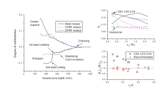
  • Moment redistribution in the beams with FRP rebars was contributed by concrete cracking, and tended to stabilize after the stabilization of crack evolution. For the beams with steel rebars, apart from the contribution by concrete cracking, steel yielding led to further development of moment redistribution;
  • Steel rebars led to significantly higher redistribution of moments than FRP rebars. The redistribution difference between the beams with steel and FRP rebars enlarged with increasing ρr2 up to 1.67% and decreased thereafter;
  • The current codes of practice investigated (Eurocode 2, CSA A23.3-04 and ACI 318-19) could not reflect the influence of both the amount, and type, of rebars on moment redistribution in PCBs with external tendons. In addition, it was found that the codes may lead to unsafe predictions in moment redistribution in beams with FRP rebars;
  • A simplified equation was recommended to predict moment redistribution in externally PCBs with steel and FRP rebars. It was shown that the recommended equation yields accurate and conservative predictions.

Author Contributions

Conceptualization, M.P. and T.L.; Methodology, M.P.; Software, T.L.; Validation, Z.L.; Formal Analysis, Z.L.; Investigation, Z.L. and M.P.; Resources, T.L.; Data Curation, Z.L.; Writing—Original Draft Preparation, T.L.; Writing—Review and Editing, M.P.; Visualization, Z.L.; Supervision, M.P. and T.L. All authors have read and agreed to the published version of the manuscript.

Funding

This research received no external funding.

Institutional Review Board Statement

Not applicable.

Informed Consent Statement

Not applicable.

Data Availability Statement

Not applicable.

Conflicts of Interest

The authors declare no conflict of interest.

References

  1. ACI Committee. Prestressing Concrete Structures with FRP Tendons. ACI 440.4R-04; ACI Committee: Farmington Hills, MI, USA, 2004. [Google Scholar]
  2. Le, T.D.; Pham, T.M.; Hao, H.; Li, H. Behavior of Precast Segmental Concrete Beams Prestressed with External Steel and CFRP Tendons. J. Compos. Constr. 2020, 24, 04020053. [Google Scholar] [CrossRef]
  3. Tan, K.H.; Tjandra, R.A. Strengthening of RC Continuous Beams by External Prestressing. J. Struct. Eng. 2007, 133, 195–204. [Google Scholar] [CrossRef]
  4. ElMesalami, N.; Abed, F.; El Refai, A. Concrete Columns Reinforced with GFRP and BFRP Bars under Concentric and Eccentric Loads: Experimental Testing and Analytical Investigation. J. Compos. Constr. 2021, 25, 04021003. [Google Scholar] [CrossRef]
  5. Zhou, A.; Chow, C.L.; Lau, D. Structural behavior of GFRP reinforced concrete columns under the influence of chloride at casting and service stages. Compos. Part B Eng. 2018, 136, 1–9. [Google Scholar] [CrossRef]
  6. Sun, W.; Lou, T.; Achintha, M. A novel strong and durable near-surface mounted (NSM) FRP method with cost-effective fillers. Compos. Struct. 2021, 255, 112952. [Google Scholar] [CrossRef]
  7. Sun, W.; He, T.; Wang, X.; Zhang, J.; Lou, T. Developing an anchored near-surface mounted (NSM) FRP system for fuller use of FRP material with less epoxy filler. Compos. Struct. 2019, 226, 111251. [Google Scholar] [CrossRef]
  8. Mostofinejad, D.; Hosseini, S.M.; Tehrani, B.N.; Eftekhar, M.R.; Dyari, M. Innovative warp and woof strap (WWS) method to anchor the FRP sheets in strengthened concrete beams. Constr. Build. Mater. 2019, 218, 351–364. [Google Scholar] [CrossRef]
  9. Bennitz, A.; Schmidt, J.W.; Nilimaa, J.; Taljsten, B.; Goltermann, P.; Ravn, D.L. Reinforced Concrete T-Beams Externally Prestressed with Unbonded Carbon Fiber-Reinforced Polymer Tendons. ACI Struct. J. 2012, 109, 521–530. [Google Scholar] [CrossRef]
  10. Lou, T.; Karavasilis, T.L. Numerical evaluation of prestressed steel-concrete composite girders with external FRP or steel tendons. J. Constr. Steel Res. 2019, 162, 105698. [Google Scholar] [CrossRef]
  11. Xue, W.; Tan, Y.; Peng, F. Experimental Study on Damaged Prestressed Concrete Beams Using External Post-Tensioned Tendons. ACI Struct. J. 2019, 117, 159–168. [Google Scholar] [CrossRef]
  12. Aravinthan, T.; Witchukreangkrai, E.; Mutsuyoshi, H. Flexural Behavior of Two-Span Continuous Prestressed Concrete Girders with Highly Eccentric External Tendons. ACI Struct. J. 2005, 102, 402–411. [Google Scholar] [CrossRef] [Green Version]
  13. Lou, T.; Lopes, S.M.R.; Lopes, A.V. Flexural Response of Continuous Concrete Beams Prestressed with External Tendons. J. Bridg. Eng. 2013, 18, 525–537. [Google Scholar] [CrossRef]
  14. Chan, K.E.; Au, F.T. Behaviour of continuous prestressed concrete beams with external tendons. Struct. Eng. Mech. 2015, 55, 1099–1120. [Google Scholar] [CrossRef]
  15. Lou, T.; Lopes, S.M.R.; Lopes, A.V. Factors affecting moment redistribution at ultimate in continuous beams prestressed with external CFRP tendons. Compos. Part B Eng. 2014, 66, 136–146. [Google Scholar] [CrossRef]
  16. Lou, T.; Peng, C.; Karavasilis, T.L.; Min, D.; Sun, W. Moment redistribution versus neutral axis depth in continuous PSC beams with external CFRP tendons. Eng. Struct. 2020, 209, 109927. [Google Scholar] [CrossRef]
  17. Lou, T.; Lopes, S.M.; Lopes, A.V. Effect of linear transformation on nonlinear behavior of continuous prestressed beams with external FRP cables. Eng. Struct. 2017, 147, 410–424. [Google Scholar] [CrossRef]
  18. ACI Committee. Building Code Requirements for Structural Concrete (ACI 318-19) and Commentary (ACI 318R-19); American Concrete Institute: Farmington Hills, MI, USA, 2019; p. 519. [Google Scholar]
  19. ACI Committee. Guide for the Design and Construction of Structural Concrete Reinforced with FRP Bars. ACI 440.1R-06; ACI Committee: Farmington Hills, MI, USA, 2006. [Google Scholar]
  20. El Refai, A.; Abed, F.; Altalmas, A. Bond durability of basalt fiber–reinforced polymer bars embedded in concrete under direct pullout conditions. ASCE J. Compos. Constr. 2015, 19, 04014078. [Google Scholar] [CrossRef]
  21. Altalmas, A.; El Refai, A.; Abed, F. Bond degradation of basalt fiber-reinforced polymer (BFRP) bars exposed to accelerated aging conditions. Constr. Build. Mater. 2015, 81, 162–171. [Google Scholar] [CrossRef]
  22. Al-Tamimia, A.; Abed, F.H.; Al-Rahmani, A. Effects of harsh environmental exposures on the bond capacity between concrete and GFRP reinforcing bars. Adv. Concr. Constr. 2014, 2, 1–11. [Google Scholar] [CrossRef]
  23. Alkhraisha, H.; Mhanna, H.; Tello, N.; Abed, F. Serviceability and Flexural Behavior of Concrete Beams Reinforced with Basalt Fiber-Reinforced Polymer (BFRP) Bars Exposed to Harsh Conditions. Polymer 2020, 12, 2110. [Google Scholar] [CrossRef]
  24. Al Rifai, M.; El-Hassan, H.; El-Maaddawy, T.; Abed, F. Durability of basalt FRP reinforcing bars in alkaline solution and moist concrete environments. Constr. Build. Mater. 2020, 243, 118258. [Google Scholar] [CrossRef]
  25. Pang, M.; Li, Z.; Lou, T. Numerical Study of Using FRP and Steel Rebars in Simply Supported Prestressed Concrete Beams with External FRP Tendons. Polymer 2020, 12, 2773. [Google Scholar] [CrossRef]
  26. Santos, P.; Laranja, G.; Franca, P.M.; Correia, J.R. Ductility and moment redistribution capacity of multi-span T-section concrete beams reinforced with GFRP bars. Constr. Build. Mater. 2013, 49, 949–961. [Google Scholar] [CrossRef]
  27. Mahroug, M.; Ashour, A.; Lam, D. Experimental response and code modelling of continuous concrete slabs reinforced with BFRP bars. Compos. Struct. 2014, 107, 664–674. [Google Scholar] [CrossRef]
  28. Dundar, C.; Tanrikulu, A.K.; Frosch, R.J. Prediction of load–deflection behavior of multi-span FRP and steel reinforced concrete beams. Compos. Struct. 2015, 132, 680–693. [Google Scholar] [CrossRef]
  29. Akiel, M.S.; El-Maaddawy, T.; El Refai, A. Serviceability and moment redistribution of continuous concrete members reinforced with hybrid steel-BFRP bars. Constr. Build. Mater. 2018, 175, 672–681. [Google Scholar] [CrossRef]
  30. Zinkaah, O.H.; Ashour, A.; Sheehan, T. Experimental tests of two-span continuous concrete deep beams reinforced with GFRP bars and strut-and-tie method evaluation. Compos. Struct. 2019, 216, 112–126. [Google Scholar] [CrossRef]
  31. Baša, N.; Vuković, N.K.; Ulićević, M.; Muhadinović, M. Effects of Internal Force Redistribution on the Limit States of Continuous Beams with GFRP Reinforcement. Appl. Sci. 2020, 10, 3973. [Google Scholar] [CrossRef]
  32. Abdallah, M.; Al Mahmoud, F.; Khelil, A.; Mercier, J.; Almassri, B. Assessment of the flexural behavior of continuous RC beams strengthened with NSM-FRP bars, experimental and analytical study. Compos. Struct. 2020, 242, 112127. [Google Scholar] [CrossRef]
  33. Lou, T.-J.; Xiang, Y.-Q. Finite element modeling of concrete beams prestressed with external tendons. Eng. Struct. 2006, 28, 1919–1926. [Google Scholar] [CrossRef]
  34. CEN. Eurocode 2: Design of Concrete Structures—Part 1-1: General Rules and Rules for Buildings. EN 1992-1-1; European Committee for Standardization: Brussels, Belgium, 2004. [Google Scholar]
  35. Lou, T.; Min, D.; Sun, W.; Chen, B. Numerical assessment of continuous prestressed NSC and HSC members with external CFRP tendons. Compos. Struct. 2020, 234, 111671. [Google Scholar] [CrossRef]
  36. CSA. Design of Concrete Structures. A23.3-04; Canadian Standards Association: Mississauga, ON, Canada, 2004. [Google Scholar]
Figure 1. Schematic diagrams of material laws. (a) concrete in compression; (b) concrete in tension; (c) tendons; (d) rebars.
Polymers 13 01181 g001
Figure 2. Continuous beam for numerical investigation.
Polymers 13 01181 g002
Figure 3. Development of end support reactions for the beams with different types of rebars.
Polymers 13 01181 g003
Figure 4. Development of bending moments for the beams with different types of rebars.
Polymers 13 01181 g004
Figure 5. Moment distribution for the beams with different types of rebars.
Polymers 13 01181 g005
Figure 6. Development of reaction ratios for the beams with different types of rebars. (a) steel rebars; (b) carbon-fiber-reinforced polymer (CFRP) rebars; (c) glass-fiber-reinforced polymer (GFRP) rebars.
Polymers 13 01181 g006
Figure 7. Development of moment ratios for the beams with different types of rebars. (a) steel rebars; (b) CFRP rebars; (c) GFRP rebars.
Polymers 13 01181 g007
Figure 8. Load versus moment redistribution curves for the beams with different types of rebars.
Polymers 13 01181 g008
Figure 9. Neutral axis depth versus moment redistribution curves for the beams with different types of rebars.
Polymers 13 01181 g009
Figure 10. Rebar strain versus moment redistribution curves for the beams with different types of rebars.
Polymers 13 01181 g010
Figure 11. Variation in βu with varying ρr2 for the beams with different types of rebars.
Polymers 13 01181 g011
Figure 12. Variation in βu with varying cu/d for the beams with different types of rebars along with the code curves (Eurocode 2 and CSA A23.3-04).
Polymers 13 01181 g012
Figure 13. Variation in βu with varying εt for the beams with different types of rebars along with the ACI 318-19 curve.
Polymers 13 01181 g013
Figure 14. Comparison of numerically predicted βu values and code predictions. (a) Eurocode 2; (b) CSA A23.3-04; (c) ACI 318-19.
Polymers 13 01181 g014
Figure 15. Values of (βu)sim/(βu)act against cu/d according to CSA A23.3-04 and recommended equations.
Polymers 13 01181 g015
Publisher’s Note: MDPI stays neutral with regard to jurisdictional claims in published maps and institutional affiliations.

