
Aging of 3D Printed Polymers under Sterilizing UV-C Radiation

 , , ,
, , ,
Abstract
:
1. Introduction
2. Materials and Methods
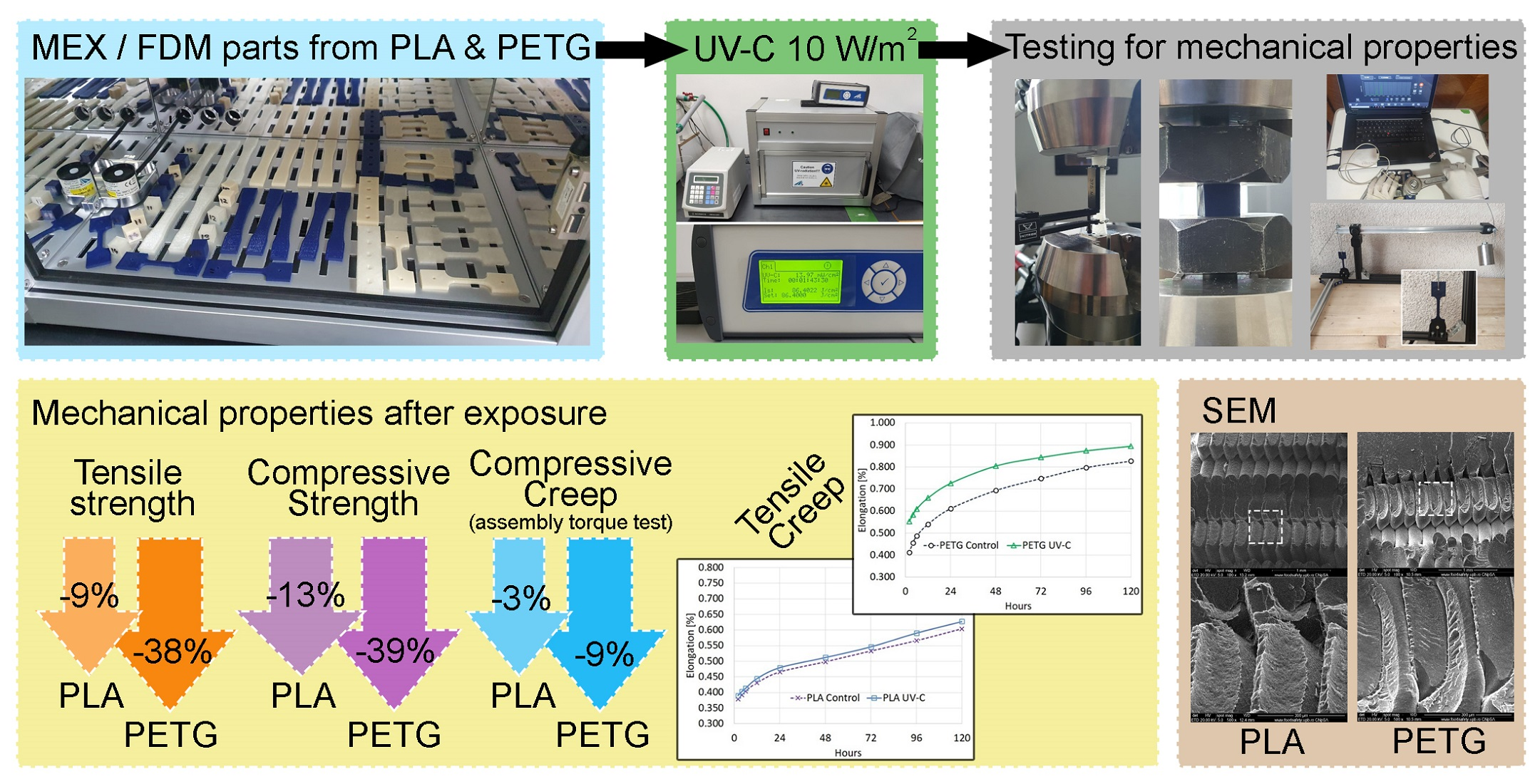
2.1. Sample 3D Printing and UV-C Exposure Protocol
2.2. Tensile Strength
2.3. Compressive Strength
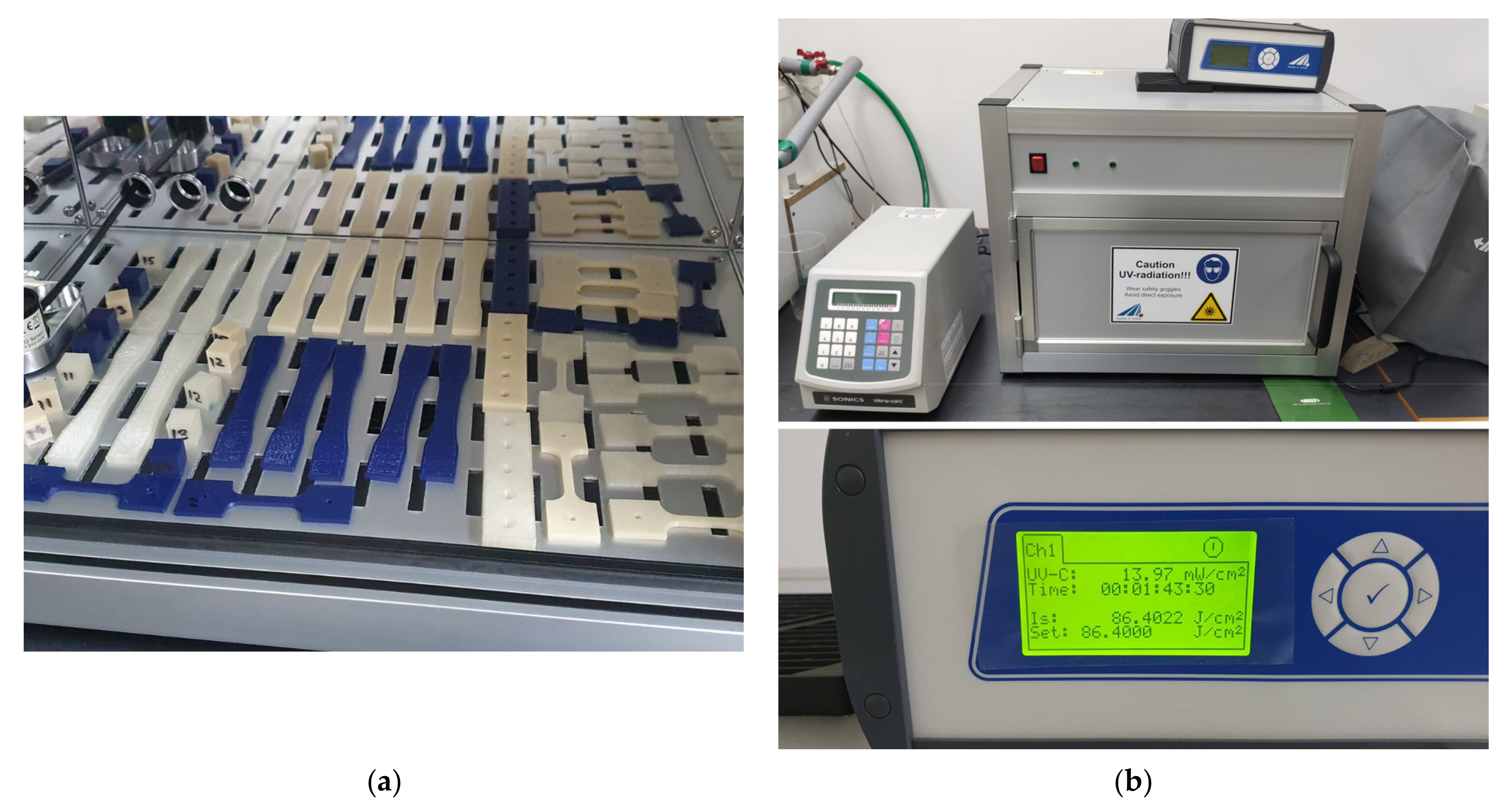
2.4. Creep Characteristics
2.5. Scanning Electron Microscopy (SEM)
3. Results
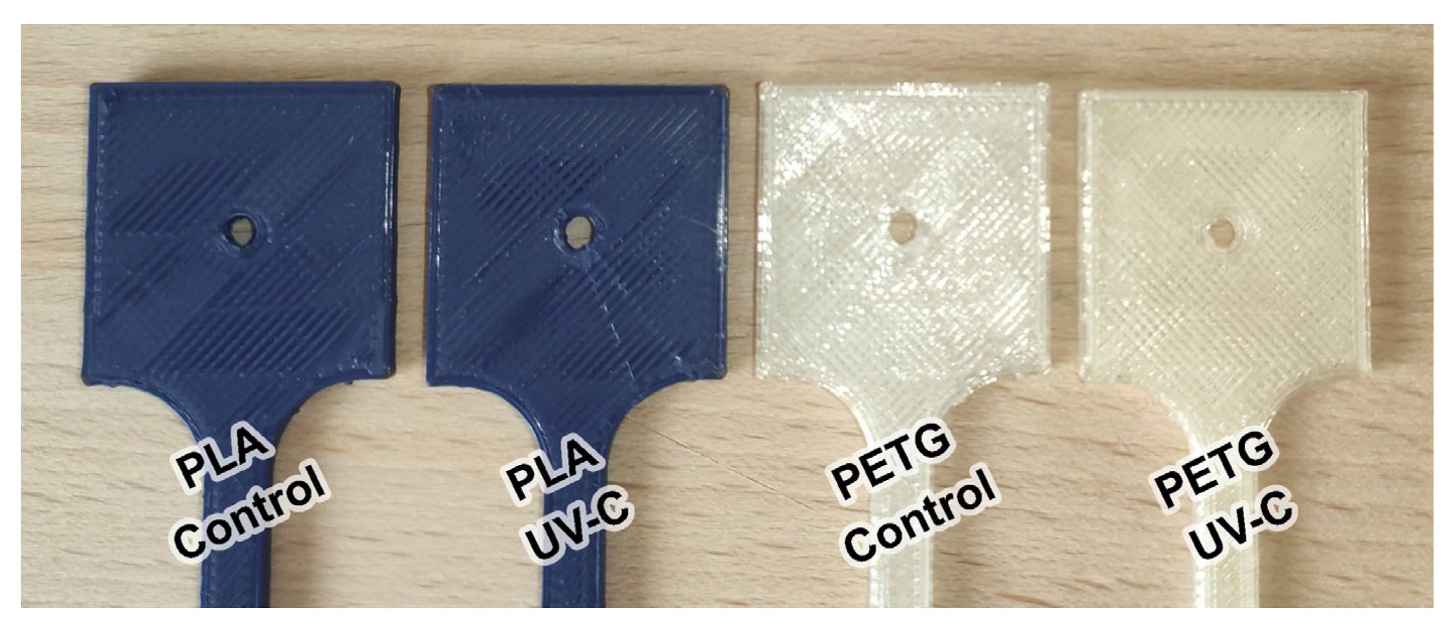
3.1. Visual and Dimensional Changes Following UV-C Exposure
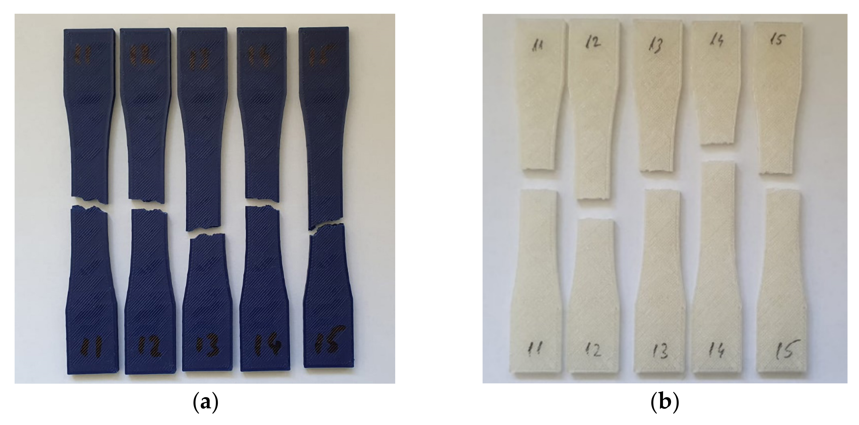
3.2. Tensile Strength and Young’s Modulus
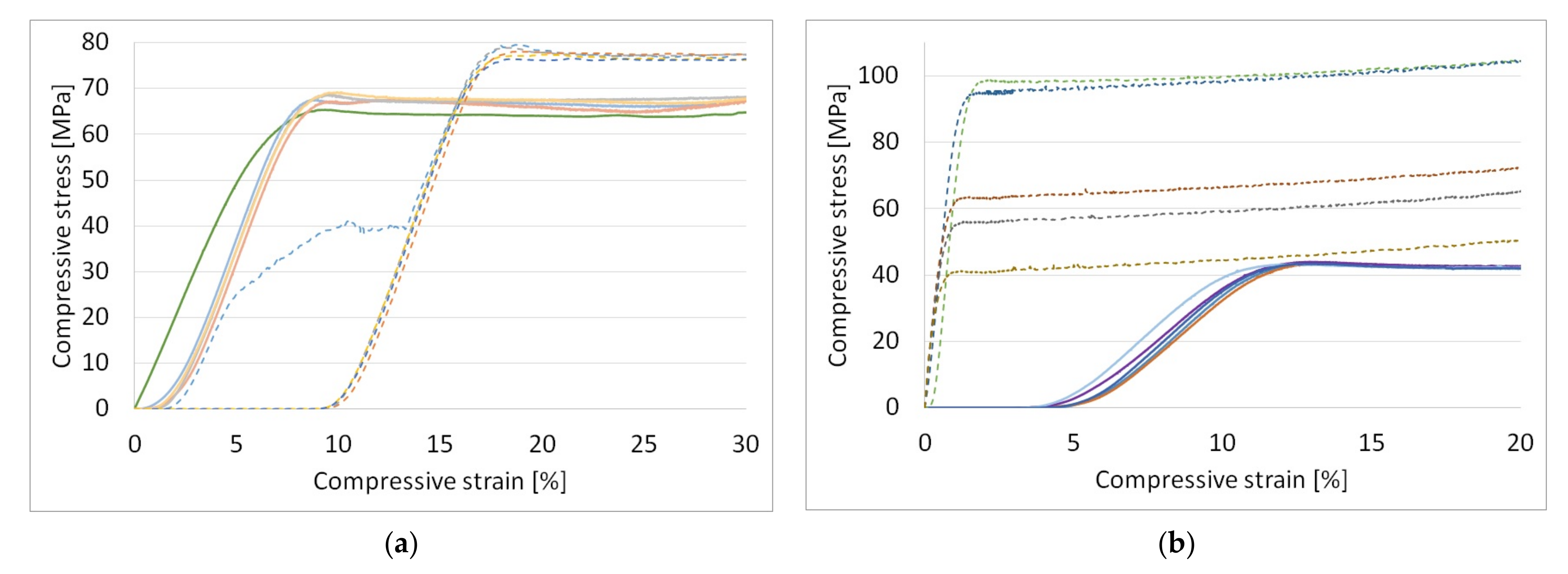
3.3. Compressive Strength
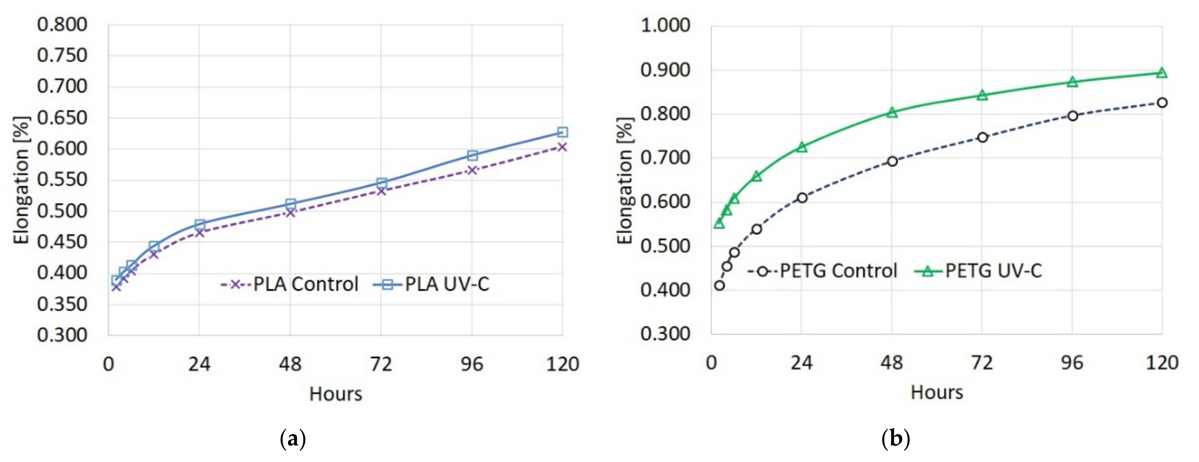
3.4. Creep Characteristics of the Analyzed Materials
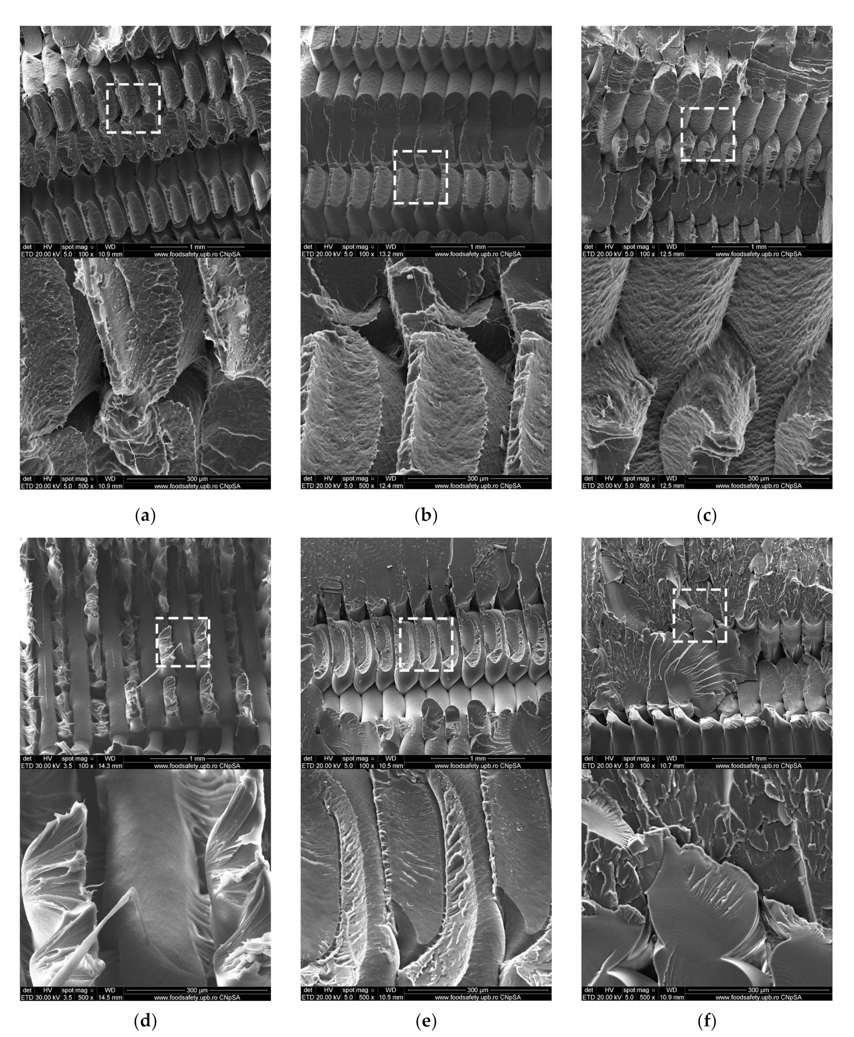
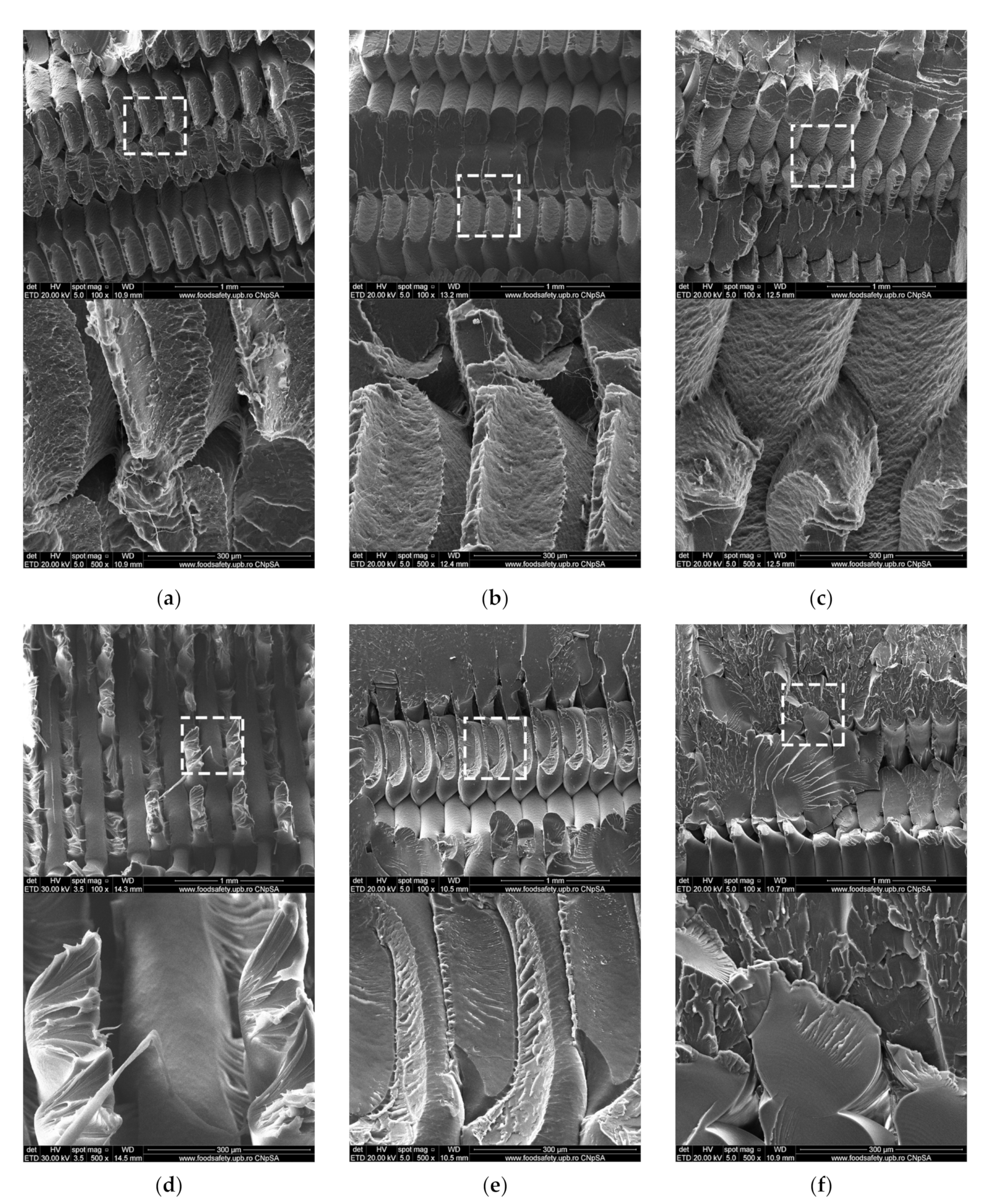
3.5. Scanning Electron Microscopy (SEM)
4. Discussion
5. Conclusions
Supplementary Materials
Author Contributions
Funding
Institutional Review Board Statement
Informed Consent Statement
Data Availability Statement
Conflicts of Interest
References
- World Health Organization. News Release: Shortage of Personal Protective Equipment Endangering Health Workers Worldwide. 3 March 2020. Available online: https://www.who.int/news/item/03-03-2020-shortage-of-personal-protective-equipment-endangering-health-workers-worldwide (accessed on 5 November 2021).
- Ranney, M.L.; Griffeth, V.; Jha, A.K. Critical Supply Shortages—The Need for Ventilators and Personal Protective Equipment during the COVID-19 Pandemic. N. Engl. J. Med. 2020, 382, e41. [Google Scholar] [CrossRef] [PubMed]
- Cohen, J.; Rodgers, Y. Contributing factors to personal protective equipment shortages during the COVID-19 pandemic. Prev. Med. 2020, 141, 106263. [Google Scholar] [CrossRef] [PubMed]
- Jessop, Z.M.; Dobbs, T.D.; Ali, S.R.; Combellack, E.; Clancy, R.; Ibrahim, N.; Jovic, T.H.; Kaur, A.J.; Nijran, A.; O’Neill, T.B.; et al. Personal protective equipment for surgeons during COVID-19 pandemic: Systematic review of availability, usage and rationing. Br. J. Surg. 2020, 107, 1262–1280. [Google Scholar] [CrossRef] [PubMed]
- Bauchner, H.; Fontanarosa, P.B.; Livingston, E.H. Conserving Supply of Personal Protective Equipment—A Call for Ideas. JAMA 2020, 323, 1911. [Google Scholar] [CrossRef] [Green Version]
- World Health Organization. Interim Guidance, Rational Use of Personal Protective Equipment for Coro-Navirus Disease (COVID-19) and Considerations during Severe Shortages. Reference Number WHO/2019-nCoV/IPC_PPE_use/2020.4. 23 December 2020. Available online: https://www.who.int/publications/i/item/rational-use-of-personal-protective-equipment-for-coronavirus-disease-(covid-19)-and-considerations-during-severe-shortages (accessed on 5 November 2021).
- Jordan, J.M. Additive manufacturing (“3D printing”) and the future of organizational design: Some early notes from the field. J. Org. Des. 2019, 8, 5. [Google Scholar] [CrossRef]
- Ben-Ner, A.; Siemsen, E. Decentralization and Localization of Production: The Organizational and Economic Consequences of Additive Manufacturing (3D Printing). Calif. Manag. Rev. 2017, 59, 5–23. [Google Scholar] [CrossRef]
- Hagen, A.; Chisling, M.; House, K.; Katz, T.; Abelseth, L.; Fraser, I.; Bradley, S.; Kirsch, R.; Morris, J.; Giles, J.W.; et al. 3D Printing for Medical Applications: Current State of the Art and Perspectives during the COVID-19 Crisis. Surgeries 2021, 2, 25. [Google Scholar] [CrossRef]
- Longhitano, G.A.; Nunes, G.B.; Candido, G.; da Silva, J.V.L. The role of 3D printing during COVID-19 pandemic: A review. Prog. Addit. Manuf. 2021, 6, 19–37. [Google Scholar] [CrossRef]
- Ford, J.; Goldstein, T.; Trahan, S.; Neuwirth, A.; Tatoris, K.; Decker, S. A 3D-printed nasopharyngeal swab for COVID-19 diagnostic testing. 3D Print. Med. 2020, 6, 21. [Google Scholar] [CrossRef]
- Manoj, A.; Bhuyan, M.; Banik, S.R.; Sankard, M.R. 3D printing of nasopharyngeal swabs for COVID-19 diagnose: Past and current trends. Mater. Today Proc. 2021, 44, 1361–1368. [Google Scholar] [CrossRef]
- Wesemann, C.; Pieralli, S.; Fretwurst, T.; Nold, J.; Nelson, K.; Schmelzeisen, R.; Hellwig, E.; Spies, B.C. 3-D Printed Protective Equipment during COVID-19 Pandemic. Materials 2020, 13, 1997. [Google Scholar] [CrossRef]
- Novak, J.I.; Loy, J. A quantitative analysis of 3D printed face shields and masks during COVID-19. Emerald Open Res. 2020, 2, 42. [Google Scholar] [CrossRef]
- Marinescu, R.; Popescu, D.; Laptoiu, D. A Review on 3D-Printed Templates for Precontouring Fixation Plates in Orthopedic Surgery. J. Clin. Med. 2020, 9, 2908. [Google Scholar] [CrossRef]
- Reponen, T.; Lee, S.-A.; Grinshpun, S.A.; Johnson, E.; Mckay, R. Effect of Fit Testing on the Protection Offered by N95 Filtering Facepiece Respirators against Fine Particles in a Laboratory Setting. Ann. Occup. Hyg. 2011, 55, 264–271. [Google Scholar] [CrossRef] [Green Version]
- O’Kelly, E.; Arora, A.; Pirog, S.; Ward, J.; Clarkson, P.J. Comparing the fit of N95, KN95, surgical, and cloth face masks and assessing the accuracy of fit checking. PLoS ONE 2021, 16, e0245688. [Google Scholar] [CrossRef]
- Dugdale, C.M.; Walensky, R.P. Filtration Efficiency, Effectiveness, and Availability of N95 Face Masks for COVID-19 Prevention. JAMA Intern. Med. 2020, 180, 1612–1613. [Google Scholar] [CrossRef]
- Ballard, D.H.; Jammalamadaka, U.; Meacham, K.W.; Hoegger, M.J.; Burke, B.A.; Morris, J.A.; Scott, A.R.; O’Connor, Z.; Gan, C.; Hu, J.; et al. Quantitative Fit Tested N95 Respirator-Alternatives Generated with CT Imaging and 3D Printing: A Response to Potential Shortages during the COVID-19 Pandemic. Acad. Radiol. 2021, 28, 158–165. [Google Scholar] [CrossRef]
- McAvoy, M.; Bui, A.-T.N.; Hansen, C.; Plana, D.; Said, J.T.; Yu, Z.; Yang, H.; Freake, J.; Van, C.; Krikorian, D.; et al. 3D Printed frames to enable reuse and improve the fit of N95 and KN95 respirators. BMC Biomed. Eng. 2021, 3, 10. [Google Scholar] [CrossRef]
- Tipnis, N.P.; Burgess, D.J. Sterilization of implantable polymer-based medical devices: A review. Int. J. Pharm. 2018, 544, 455–460. [Google Scholar] [CrossRef]
- Ghobeira, R.; Philips, C.; Declercq, H.; Cools, P.; De Geyter, N.; Cornelissen, R.; Morent, R. Effects of different sterilization methods on the physico-chemical and bioresponsive properties of plasma-treated polycaprolactone films. Biomed. Mater. 2017, 12, 015017. [Google Scholar] [CrossRef] [Green Version]
- Holmes, S. 20—An overview of current surgical instrument and other medical device decontamination practices. In Woodhead Publishing Series in Biomaterials, Decontamination in Hospitals and Healthcare, 2nd ed.; Walker, J., Ed.; Woodhead Publishing: Sawston, UK, 2020; pp. 443–482. ISBN 9780081025659. [Google Scholar] [CrossRef]
- Sadeque, M.; Balachandran, S.K. 10—Overview of medical device processing. In Trends in Development of Medical Devices; Shanmugam, P.S.T., Chokkalingam, L., Bakthavachalam, P., Eds.; Academic Press: Cambridge, MA, USA, 2020; pp. 177–188. ISBN 9780128209608. [Google Scholar] [CrossRef]
- McEvoy, B.; Rowan, N. Terminal sterilization of medical devices using vaporized hydrogen peroxide: A review of current methods and emerging opportunities. J. Appl. Microbiol. 2019, 127, 1403–1420. [Google Scholar] [CrossRef] [Green Version]
- Grzelak, K.; Łaszcz, J.; Polkowski, J.; Mastalski, P.; Kluczyński, J.; Łuszczek, J.; Torzewski, J.; Szachogłuchowicz, I.; Szymaniuk, R. Additive Manufacturing of Plastics Used for Protection against COVID-19—The Influence of Chemical Disinfection by Alcohol on the Properties of ABS and PETG Polymers. Materials 2021, 14, 4823. [Google Scholar] [CrossRef]
- Popescu, D.; Baciu, F.; Vlasceanu, D.; Cotrut, M.C.; Marinescu, R. Effects of multiple sterilizations and natural aging on the mechanical behavior of 3D-printed ABS. Mech. Mater. 2020, 148, 103423. [Google Scholar] [CrossRef]
- Pérez Davila, S.; González Rodríguez, L.; Chiussi, S.; Serra, J.; González, P. How to Sterilize Polylactic Acid Based Medical Devices? Polymers 2021, 13, 2115. [Google Scholar] [CrossRef]
- Lindsley, W.G.; Martin, S.B., Jr.; Thewlis, R.E.; Sarkisian, K.; Nwoko, J.O.; Mead, K.R.; Noti, J.D. Effects of Ultraviolet Germicidal Irradiation (UVG) on N95 Respirator Filtration Performance and Structural Integrity. J. Occup. Environ. Hyg. 2015, 12, 509–517. [Google Scholar] [CrossRef]
- Van Doremalen, N.; Bushmaker, T.; Morris, D.H. Letter to the Editor: Aerosol and Surface Stability of HCoV-19 (SARS-CoV-2) Compared to SARS-CoV-1. N. Engl. J. Med. 2020, 382, 1564–1567. [Google Scholar] [CrossRef]
- Stojalowski, P.S.; Fairfoull, J. Comparison of Reflective Properties of Materials Exposed to Ultraviolet-C Radiation. J. Res. Natl. Inst. Stand. Technol. 2021, 126, 126017. [Google Scholar] [CrossRef]
- Spicer, D.B. Methods and Mechanisms of Photonic Disinfection. J. Res. Natl. Inst. Stand. Technol. 2021, 126, 126016. [Google Scholar] [CrossRef]
- Standard ISO 4892-3:2016. Plastics—Methods of Exposure to Laboratory Light Sources—Part 3: Fluorescent UV Lamps. Available online: https://www.iso.org/standard/67793.html (accessed on 6 November 2021).
- Yu, M.; Zheng, Y.; Tian, J. Study on the biodegradability of modified starch/polylactic acid (PLA) composite materials. RSC Adv. 2020, 10, 26298–26307. [Google Scholar] [CrossRef]
- Chaochanchaikul, K.; Harnnarongchai, W. Influence of Multifunctional Monomers on Gamma Irradiated Polylactic Acid. Appl. Mech. Mater. 2015, 804, 59–62. [Google Scholar] [CrossRef]
- Cairns, M.-L.; Dickson, G.R.; Orr, J.F.; Farrar, D.; Hawkins, K.; Buchanan, F.J. Electron-beam treatment of poly(lactic acid) to control degradation profiles. Polym. Degrad. Stab. 2011, 96, 76–83. [Google Scholar] [CrossRef] [Green Version]
- Nugroho, P.; Mitomo, H.; Yoshii, F.; Kume, T. Degradation of poly(l-lactic acid) by γ-irradiation. Polym. Degrad. Stab. 2001, 72, 337–343. [Google Scholar] [CrossRef]
- The National Institute of Standards and Technology. Summary of Event and Post-Workshop Activities. March 2020. Available online: https://www.nist.gov/news-events/events/2020/01/workshop-ultraviolet-disinfection-technologies-healthcare-associated-4 (accessed on 5 November 2021).
- International Ultraviolet Association (IUVA). Fact Sheet on UV Disinfection for COVID-19. Available online: https://www.iuva.org/IUVA-Fact-Sheet-on-UV-Disinfection-for-COVID-19 (accessed on 5 November 2021).
- Poster, D.L.; Miller, C.C.; Martinello, R.A.; Horn, N.R.; Postek, M.T.; Cowan, T.E.; Obeng, Y.S.; Kasianowicz, J.J. Ultraviolet Radiation Technologies and Healthcare Associated Infections: Standards and Metrology Needs. J. Res. Natl. Inst. Stand. Technol. 2021, 126, 126014. [Google Scholar] [CrossRef]
- Kreitenberg, A.; Martinello, R.A. Perspectives and Recommendations Regarding Standards for Ultraviolet-C Whole-Room Disinfection in Healthcare. J. Res. Natl. Inst. Stand. Technol. 2021, 126, 126015. [Google Scholar] [CrossRef]
- Irving, D.; Lamprou, D.A.; Maclean, M.; MacGregor, S.J.; Anderson, J.G.; Grant, M.H. A comparison study of the degradative effects and safety implications of UVC and 405 nm germicidal light sources for endoscope storage. Polym. Degrad. Stab. 2016, 133, 249–254. [Google Scholar] [CrossRef] [Green Version]
- Geldert, A.; Balch, H.B.; Gopal, A.; Su, A.; Grist, S.M.; Herr, A.E. Best Practices for Germicidal Ultraviolet-C Dose Measurement for N95 Respirator Decontamination. J. Res. Natl. Inst. Stand. Technol. 2021, 126, 126020. [Google Scholar] [CrossRef]
- Copinet, A.; Rousse, C.; Govindin, S.; Coma, V.; Couturier, Y. Effects of ultraviolet light (315 nm), temperature and relative humidity on the degradation of polylactic acid plastic films. Chemosphere 2004, 55, 763–773. [Google Scholar] [CrossRef]
- Zhang, C.; Rathi, S.; Goddard, J.; Constantine, K.; Collins, P. The Effect of UV Treatment on the Degradation of Compostable Polylactic Acid. J. Emerg. Investig. 2013, 1, 1–6. Available online: https://emerginginvestigators.org/articles/the-effect-of-uv-treatment-on-the-degradation-of-compostable-polylactic-acid/pdf (accessed on 18 December 2021).
- Arangdad, K.; Yildirim, E.; Detwiler, A.; Cleven, C.D.; Burk, C.; Shamey, R.; Pasquinelli, M.A.; Freeman, H.S.; El-Shafei, A. Influence of UV stabilizers on the weathering of PETG and PCTT films. J. Appl. Polym. Sci. 2019, 136, 48198. [Google Scholar] [CrossRef]
- Lim, S.D.; Rhee, J.M.; Nah, C.; Lee, S.-H.; Lyu, M.-Y. Predicting the Long-Term Creep Behavior of Plastics Using the Short-Term Creep Test. Int. Polym. Process. 2004, 19, 313–319. [Google Scholar] [CrossRef]
- Morreale, M.; Mistretta, M.C.; Fiore, V. Creep Behavior of Poly(lactic acid) Based Biocomposites. Materials 2017, 10, 395. [Google Scholar] [CrossRef] [Green Version]
- Martins, C.; Pinto, V.; Guedes, R.M.; Marques, A.T. Creep and Stress Relaxation Behaviour of PLA-PCL Fibres—A Linear Modelling Approach. Proc. Eng. 2015, 114, 768–775. [Google Scholar] [CrossRef] [Green Version]
- Siengchin, S.; Pohl, T.; Medina, L.; Mitschang, P. Structure and properties of flax/polylactide/alumina nanocomposites. J. Reinf. Plast. Compos. 2013, 32, 23–33. [Google Scholar] [CrossRef]
- Romeijn, T.; Singh, K.; Behrens, M.; Paul, G. Effect of accelerated weathering on the creep behaviour of additively manufactured Polyethylene Terephthalate Glycol (PETG). J. Polym. Res. 2021, 28, 352. [Google Scholar] [CrossRef]
- Chou, C.-E.; Liu, Y.-L.; Zhang, Y.; Hsueh, C.-H.; Yang, F.; Lee, S. Thermomechanical deformation of polyethylene-terephthalate artificial muscles. Polymer 2020, 210, 123013. [Google Scholar] [CrossRef]
- Tezel, T.; Kovan, V.; Topal, E.S. Effects of the printing parameters on short-term creep behaviors of three-dimensional printed polymers. J. Appl. Polym. Sci. 2019, 136, 47564. [Google Scholar] [CrossRef]
- Mohammadizadeh, M.; Fidan, I.; Allen, M.; Imeri, A. Creep behavior analysis of additively manufactured fiber-reinforced components. Int. J. Adv. Manuf. 2018, 99, 1225–1234. [Google Scholar] [CrossRef]
- Business and Institutional Furniture Manufacturers Association (BIFMA). Health Care Furniture Design—Guidelines for Cleanability; Standard BIFMA HCF 8.1-2014; BIFMA: Grand Rapids, MI, USA, 2014; Available online: https://www.ahe.org/system/files/media/file/2019/05/BIFMACleanGuide6Oct14.pdf (accessed on 18 December 2021).
- Standard ISO 4892-1:2016. Plastics—Methods of Exposure to Laboratory Light Sources—Part 1: General Guidance. Available online: https://www.iso.org/standard/60048.html (accessed on 5 November 2021).
- Standard ISO 4582:2017. Plastics—Determination of Changes in Colour and Variations in Properties after Exposure to Glass-Filtered Solar Radiation, Natural Weathering or Laboratory Radiation Sources. Available online: https://www.iso.org/standard/67791.html (accessed on 5 November 2021).
- Podsiadły, B.; Skalski, A.; Rozpiórski, W.; Słoma, M. Are We Able to Print Components as Strong as Injection Molded?—Comparing the Properties of 3D Printed and Injection Molded Components Made from ABS Thermoplastic. Appl. Sci. 2021, 11, 6946. [Google Scholar] [CrossRef]
- Ćwikła, G.; Grabowik, C.; Kalinowski, K.; Paprocka, I.; Ociepka, P. The influence of printing parameters on selected mechanical properties of FDM/FFF 3D-printed parts. IOP Conf. Ser. Mater. Sci. Eng. 2017, 227, 012033. [Google Scholar] [CrossRef]
- Standard ASTM D638-14. Standard Test Method for Tensile Properties of Plastics. Available online: https://www.astm.org/Standards/D638 (accessed on 5 November 2021).
- Laureto, J.; Pearce, J. Anisotropic mechanical property variance between ASTM D638-14 type i and type iv fused filament fabricated specimens. Polym. Test. 2018, 68, 294–301. [Google Scholar] [CrossRef] [Green Version]
- Standard ASTM D2990-01. Standard Test Methods for Tensile, Compressive, and Flexural Creep and Creep-Rupture of Plastics. Available online: https://www.astm.org/Standards/D2990.htm (accessed on 5 November 2021).
- Zou, R.; Xia, Y.; Liu, S.; Ping Hu, P.; Hou, W.; Hu, Q.; Shan, C. Isotropic and anisotropic elasticity and yielding of 3D printed material. Compos. B Eng. 2016, 99, 506–513. [Google Scholar] [CrossRef]
- Costa, S.F.; Duarte, F.M.; Covas, J.A. Thermal conditions affecting heat transfer in FDM/FFE: A contribution towards the numerical modelling of the process. Virtual Phys. Prototyp. 2015, 10, 35–46. [Google Scholar] [CrossRef]
- Phan, D.D.; Swain, Z.R.; Mackay, M.E. Rheological and heat transfer effects in fused filament fabrication. J. Rheol. 2018, 62, 1097. [Google Scholar] [CrossRef]
- Pickett, J.; Gardner, M.; Gibson, D.; Rice, S. Global weathering of aromatic engineering thermoplastics. Polym. Degrad. Stabil. 2005, 90, 405–417. [Google Scholar] [CrossRef]
- Wang, W.; Taniguchi, A.; Fukuhara, M.; Okada, T. Two-step photodegradation process of poly(ethylene terephthalate). J. Appl. Polym. Sci. 1999, 74, 306–310. [Google Scholar] [CrossRef]
- Wickramasinghe, S.; Do, T.; Tran, P. FDM-Based 3D Printing of Polymer and Associated Composite: A Review on Mechanical Properties, Defects and Treatments. Polymers 2020, 12, 1529. [Google Scholar] [CrossRef]
- Wang, X.; Zhao, L.; Fuh, J.Y.H.; Lee, H.P. Effect of Porosity on Mechanical Properties of 3D Printed Polymers: Experiments and Micromechanical Modeling Based on X-ray Computed Tomography Analysis. Polymers 2019, 11, 1154. [Google Scholar] [CrossRef] [Green Version]
- Allen, N.S.; Edge, M.; Mohammadian, M.; Jones, K. Physicochemical aspects of the environmental degradation of poly(ethylene terephthalate). Polym. Degrad. Stabil. 1994, 43, 229–237. [Google Scholar] [CrossRef]
- Chen, T.; Zhang, J.; You, H. Photodegradation behavior and mechanism of poly(ethylene glycol-co-1,4-cyclohexanedimethanol terephthalate) (PETG) random copolymers: Correlation with copolymer composition. RSC Adv. 2016, 6, 102778–102790. [Google Scholar] [CrossRef]
- Rasselet, D.; Ruellan, A.; Guinault, A.; Miquelard-Garnier, G.; Sollogoub, C.; Fayolle, B. Oxidative degradation of polylactide (PLA) and its effects on physical and mechanical properties. Eur. Polym. J. 2014, 50, 109–116. [Google Scholar] [CrossRef] [Green Version]
- Can, U.; Kaynak, C. Performance of polylactide against UV irradiation: Synergism of an organic UV absorber with micron and nano-sized TiO2. J. Compos. Mater. 2020, 54, 2489–2504. [Google Scholar] [CrossRef]
- Yousif, E.; Haddad, R. Photodegradation and photostabilization of polymers, especially polystyrene: Review. SpringerPlus 2013, 2, 398. [Google Scholar] [CrossRef] [Green Version]
- Salač, J.; Sera, J.; Jurča, M.; Verney, V.; Marek, A.; Koutny, M. Photodegradation and Biodegradation of Poly(Lactic) Acid Containing Orotic Acid as a Nucleation Agent. Materials 2019, 12, 481. [Google Scholar] [CrossRef] [Green Version]
- Hsueh, M.-H.; Lai, C.-J.; Chung, C.-F.; Wang, S.-H.; Huang, W.-C.; Pan, C.-Y.; Zeng, Y.-S.; Hsieh, C.-H. Effect of Printing Parameters on the Tensile Properties of 3D-Printed Polylactic Acid (PLA) Based on Fused Deposition Modeling. Polymers 2021, 13, 2387. [Google Scholar] [CrossRef]


| Material | Nozzle Diameter | Layer Height | Contours | Infill | Infill Pattern | Extrusion Temp. | Bed Temp. |
|---|---|---|---|---|---|---|---|
| PLA | 0.40 mm | 0.20 mm | 2 | 100% | Grid 45°/45° | 205 °C | 45 °C |
| PETG | 235 °C | 65 °C |
| Tensile Creep Specimen | Compression Creep Specimen | |||
|---|---|---|---|---|
| Width | Height | Y | Z | |
| Nominal [mm] | 5.20 | 3.00 | 25.20 | 8.00 |
| PLA Control [mm] | 5.204 ± 0.006 | 3.000 ± 0.004 | 25.188 ± 0.006 | 8.076 ± 0.013 |
| PLA UV-C [mm] | 5.196 ± 0.005 | 2.998 ± 0.006 | 25.194 ± 0.009 | 8.082 ± 0.007 |
| PETG Control [mm] | 5.210 ± 0.008 | 3.014 ± 0.005 | 25.280 ± 0.012 | 7.604 ± 0.004 |
| PETG UV-C [mm] | 5.224 ± 0.011 | 3.006 ± 0.010 | 25.304 ± 0.017 | 7.608 ± 0.006 |
| Property | PLA (Control) | PLA (UV-C) | PETG (Control) | PETG (UV-C) |
|---|---|---|---|---|
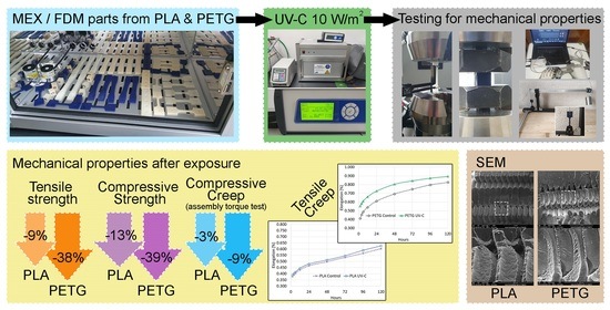
| Tensile strength | 29.54 ± 0.35 | 26.86 ± 0.35 | 31.30 ± 0.24 | 19.48 ± 0.46 |
| Young’s Modulus | 2775 ± 26.3 | 2721 ± 27.7 | 1648 ± 21.5 | 1552 ± 11.13 |
| Property | PLA (Control) | PLA (UV-C) | PETG (Control) | PETG (UV-C) |
|---|---|---|---|---|
| Compressive str. | 78.06 ± 0.55 | 67.69 ± 0.67 | 65.94 ± 9.0 | 43.57 ± 0.13 |
| Material | Tensile Properties | Compressive Properties | ||||||
|---|---|---|---|---|---|---|---|---|
| Strength [MPa] | Creep Test [MPa] | Target Load [N] | Applied Load [N] | Strength [MPa] | Torque [N·m] | Applied Load [N] | Creep Test [MPa] | |
| PLA | 29.54 | 7.5 | 117 | 12.5 × 9.4 | 78.06 | 5.07 | 2816 | 40.9 |
| PETG | 31.3 | 8 | 125 | 12.5 × 10 | 65.94 | |||
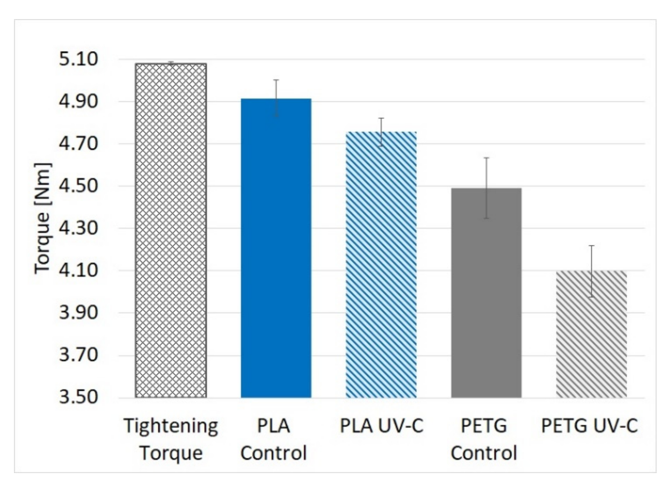
| Property | PLA (Control) | PLA (UV-C) | PETG (Control) | PETG (UV-C) |
|---|---|---|---|---|
| Torque [N·m] | 4.92 ± 0.04 | 4.76 ± 0.04 | 4.49 ± 0.06 | 4.10 ± 0.05 |
Publisher’s Note: MDPI stays neutral with regard to jurisdictional claims in published maps and institutional affiliations. |
© 2021 by the authors. Licensee MDPI, Basel, Switzerland. This article is an open access article distributed under the terms and conditions of the Creative Commons Attribution (CC BY) license (https://creativecommons.org/licenses/by/4.0/).
Share and Cite
Amza, C.G.; Zapciu, A.; Baciu, F.; Vasile, M.I.; Popescu, D. Aging of 3D Printed Polymers under Sterilizing UV-C Radiation. Polymers 2021, 13, 4467. https://doi.org/10.3390/polym13244467
Amza CG, Zapciu A, Baciu F, Vasile MI, Popescu D. Aging of 3D Printed Polymers under Sterilizing UV-C Radiation. Polymers. 2021; 13(24):4467. https://doi.org/10.3390/polym13244467
Chicago/Turabian StyleAmza, Catalin Gheorghe, Aurelian Zapciu, Florin Baciu, Mihai Ion Vasile, and Diana Popescu. 2021. "Aging of 3D Printed Polymers under Sterilizing UV-C Radiation" Polymers 13, no. 24: 4467. https://doi.org/10.3390/polym13244467