Article

Electrochemical Behavior of Inductively Sintered Al/TiO2 Nanocomposites Reinforced by Electrospun Ceramic Nanofibers

1
Center of Excellence for Research in Engineering Materials (CEREM), King Saud University, P.O. Box 800, Riyadh 11421, Saudi Arabia
2
Mechanical Design and Materials Department, Faculty of Energy Engineering, Aswan University, Aswan 81521, Egypt
3
Department of Biomedical Engineering, Faculty of Engineering, Minia University, Minia 61519, Egypt
4
Department of Electrical Engineering, College of Engineering, Taif University, P.O. Box 11099, Taif 21944, Saudi Arabia
*
Author to whom correspondence should be addressed.
Polymers 2021, 13(24), 4319; https://doi.org/10.3390/polym13244319
Submission received: 31 October 2021 / Revised: 7 December 2021 / Accepted: 8 December 2021 / Published: 9 December 2021
(This article belongs to the Special Issue Applications of Electrospun Nanofibers)

Abstract

:
This study is focuses on the investigation of the effect of using TiO2 short nanofibers as a reinforcement of an Al matrix on the corrosion characteristics of the produced nanocomposites. The TiO2 ceramic nanofibers used were synthesized via electrospinning by sol-gel process, then calcinated at a high temperature to evaporate the residual polymers. The fabricated nanocomposites contain 0, 1, 3 and 5 wt.% of synthesized ceramic nanofibers (TiO2). Powder mixtures were mixed for 1 h via high-energy ball milling in a vacuum atmosphere before being inductively sintered through a high-frequency induction furnace at 560 °C for 6 min. The microstructure of the fabricated samples was studied by optical microscope and field emission scanning electron microscope (FESEM) before and after corrosion studies. Corrosion behavior of the sintered samples was evaluated by both electrochemical impedance spectroscopy (EIS) and potentiodynamic polarization techniques (PPT) in 3.5% NaCl solution for one hour and 24-h immersion times. The results show that even though the percentage of ceramic nanofibers added negatively control corrosion resistance, it is still possible to increase resistance against corrosion for the fabricated nanocomposite by more than 75% in the longer exposure time periods.

1. Introduction

A pure heart is a powerful heart, but a pure material is not enough to endure in tough environments. Scientists all over the world are working hard and continuously to develop more efficient composite materials with better properties by mixing different materials with different phases. Composites consist of two main structures: the base matrix, which is the core element, and the additives or reinforcements embedded in the base matrix [1]. In metal matrix composites (MMC), the base matrix is metal [2], and reinforcements can be any other structure, such as nanoparticles [3], nanotubes [4], nanorods [5] or nanofibers [6,7]. According to Adebisi et al. [8], aluminum is the most common metallic material that can be used as a matrix material, owing to its high strength, acceptable thermal and electrical conductivity, better corrosion and electrochemical behavior [9]. For conventional reinforcement of MMCs, flake and particulate types of ceramic reinforcements are mostly used [10,11,12,13]. Nonetheless, the interference between the metallic matrix and the ceramic reinforcements is generally not perfect, which produces incredibly porous composites with fewer mechanical properties and higher corrosion sensibility [14]. As a way to resolve this problem, nanofibers have been introduced as a novel form of reinforcement in MMCs [15,16,17,18,19,20,21]. The mechanical properties of Al composites are efficiently enhanced in the case of using nanofibers as a reinforcement [20,21] Accordingly, the high surface-to-volume ratio of nanofibers is effectively improved. The strength and stiffness of Al composites is better than that of micro-fibers, due to the good interface between the nano ceramic reinforcement and the metal matrix [6,20]. Electrospun ceramic nanofibers (CNFs) have shown many exceptional features and have been widely implemented in many diverse applications [22,23,24].
Ceramic nanofibers are an brilliant reinforcement material [25] due to their exceptional mechanical and electrochemical properties, such as high strength and elastic modulus, as well as good chemical and thermal stability [26]. TiO2 ceramic nanofiber reinforcement, in combination with an Al metal matrix, effectively improves the mechanical properties of the nanocomposite [6]. Research in recent years has been focused on carbon nanofibers and carbon nanotubes as a reinforcement for MMC. Until now, there has been a limited number of studies in which ceramic nanofibers have been successfully introduced in metallic matrix materials resulting in significant improvements in mechanical and electrochemical properties [27,28].
A high-frequency induction-heated sintering (HFIHS) process is one of the most effective consolidation techniques in which simultaneous pressure and temperature are applied to the powder mixture sample in a vacuumed atmosphere within a very short time to produce a high-density and homogeneous composite [29,30]. This advanced sintering process is beneficial because its densification ability is very good, which produces high-density samples with convergent real and theoretical densities, i.e., relative density is very close to 100% [31]. However, extensive research has been conducted in the last few years on MMC reinforced by nanofibers and the development of its mechanical properties. Still, there is a knowledge gap concerning corrosion resistance and electrochemical characteristics of these composites, especially those reinforced by ceramic nanofibers [32,33].
Electrospinning produces nanofibers from polymeric material and can produce inorganic nanofibers by combining different inorganic nanoparticles with polymer solutions in order to alter and improve their properties [34,35,36,37]. The combination of electrospinning with other traditional methods has improved the properties of electrospun nanofibers for a wide variety of functional applications. Therefore, in the current study, TiO2 ceramic nanofibers were synthesized via electrospinning technique and sol-gel method to be used as a reinforcement for pure a Al matrix. The effect of different reinforcement ratios on the electrochemical characteristics and corrosion behavior of the fabricated nanocomposite in 3.5% NaCl solution was investigated using various electrochemical techniques. Specifically, electrochemical techniques adopted were electrochemical impedance spectroscopy (EIS) and POTENTIODYNAMIC POLARIZATION TECHNIQUES (PPT). Characterization of powder mixture morphology was performed using field emission scanning electron microscopy (FESEM). Characterization of chemical composition was performed using X-ray diffraction (XRD) spectra along the sample’s preparation steps.

2. Experimental Procedure

2.1. Raw Materials

Aluminum fine powder with 98% purity and an average particle size of 45 μm was purchased from Loba Chemie (Mumbai, India) to be used as base matrix. Polyvinylpyrrolidone (PVP) with a molecular weight of 1,300,000 kg/mole was obtained from Sigma–Aldrich (Burlington, MA, USA), Titanium isopropoxide (C12 H28 O4 Ti). Ethanol (96% purity) was obtained from Avonchem (Macclesfield, Cheshire, UK), and Acetic Acid 99.7% was obtained from Qualikems (Delhi, India).

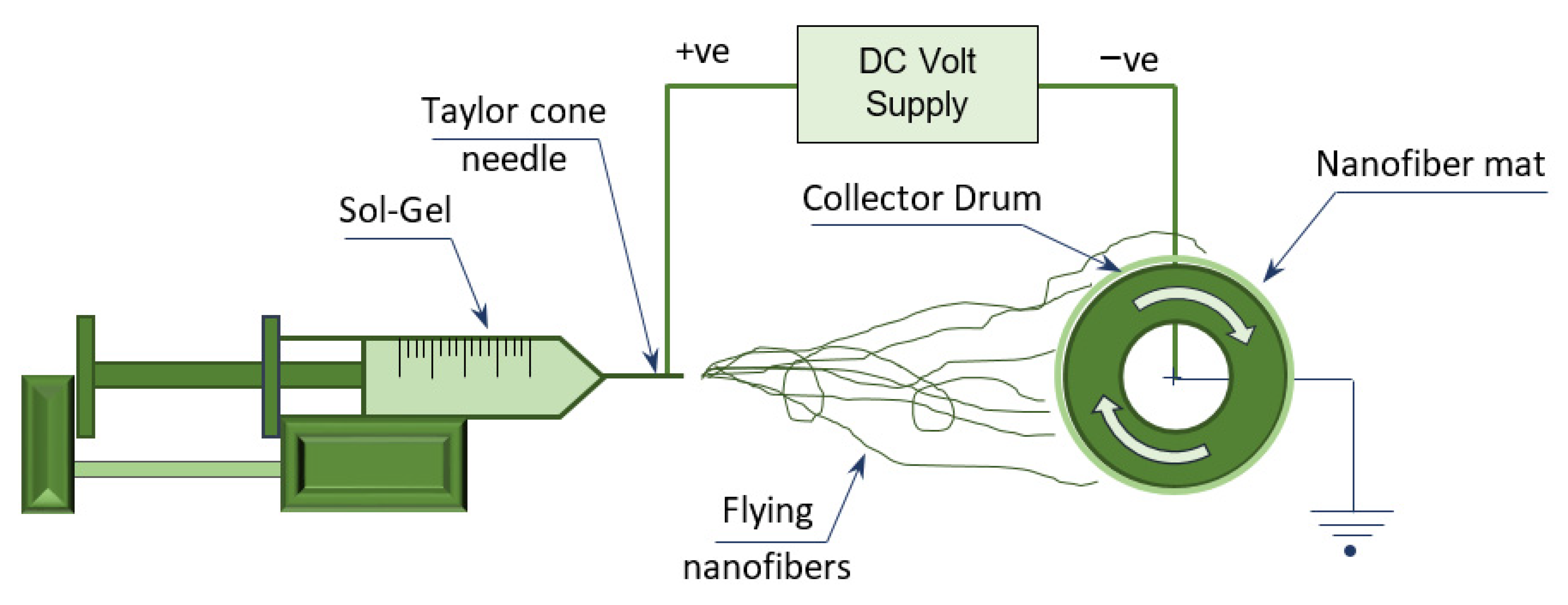
2.2. Ceramic Nanofiber Preparation

Ceramic nanofibers from TiO2 were successfully prepared via sol-gel method by electrospinning of Titanium isopropoxide and PVP (Figure 1), then calcining the produced nanofiber mats in an oxidized environment in order to evaporate the polymer. The mats were then held over the ceramic content of TiO2. Sol-Gel was prepared by stirring the solution with gelation for 2–3 h at room temperature in order to produce a clear, transparent, homogeneous mixture. The solution was made by adding 6.75 gm of Ti (IV)-isopropoxide (C12 H28 O4 Ti) to 13.5 mL of acetic acid, while gelation was achieved by adding 2.25 gm of PVP to 45 gm of ethanol.
The prepared sol-gel was poured into a plastic syringe with 20 mL capacity, then loaded on the electrospinning device shown in Figure 1. The electrospinning process was performed using three basic components: high-voltage source (20–22 kV), a syringe with small-diameter needle and a collecting drum of low rotation speed (70–90 rpm).

2.3. Calcination Process

In order to convert the polymeric nanofibers prepared by electrospinning to ceramic nanofibers, a calcination process was necessary, in which the green nanofiber mat was burned in air environment at high temperature but below its melting point. The availability of oxygen in the surrounding environment during calcination helped the volatilization reaction to takes place above the thermal decomposition temperature of the burned nanofibers. In the current study, TiO2 nanofiber was calcined at 750 °C for 150 min with a heating rate of 12 °C/min using a tube furnace (CARBOLITE Type 3216CC, Chelmsford, Essex, UK).

2.4. Composite Preparation

A mixture of Al and TiO2 NF was prepared via high-energy ball milling (HEBM) using a planetary ball mill (Pulverisette 7, Fritsch, Idar-Oberstein, Germany) with zirconium balls and stainless-steel jars. The mixing process was performed with a powder-to-balls ratio of 2:1 wt.% and a speed of 100 rpm for 1 h total milling time (30 min milling + 30 min break + 30 min milling). The percentage of ceramic nanofibers used was 0, 1, 3 and 5 wt.% of the total mixture content.

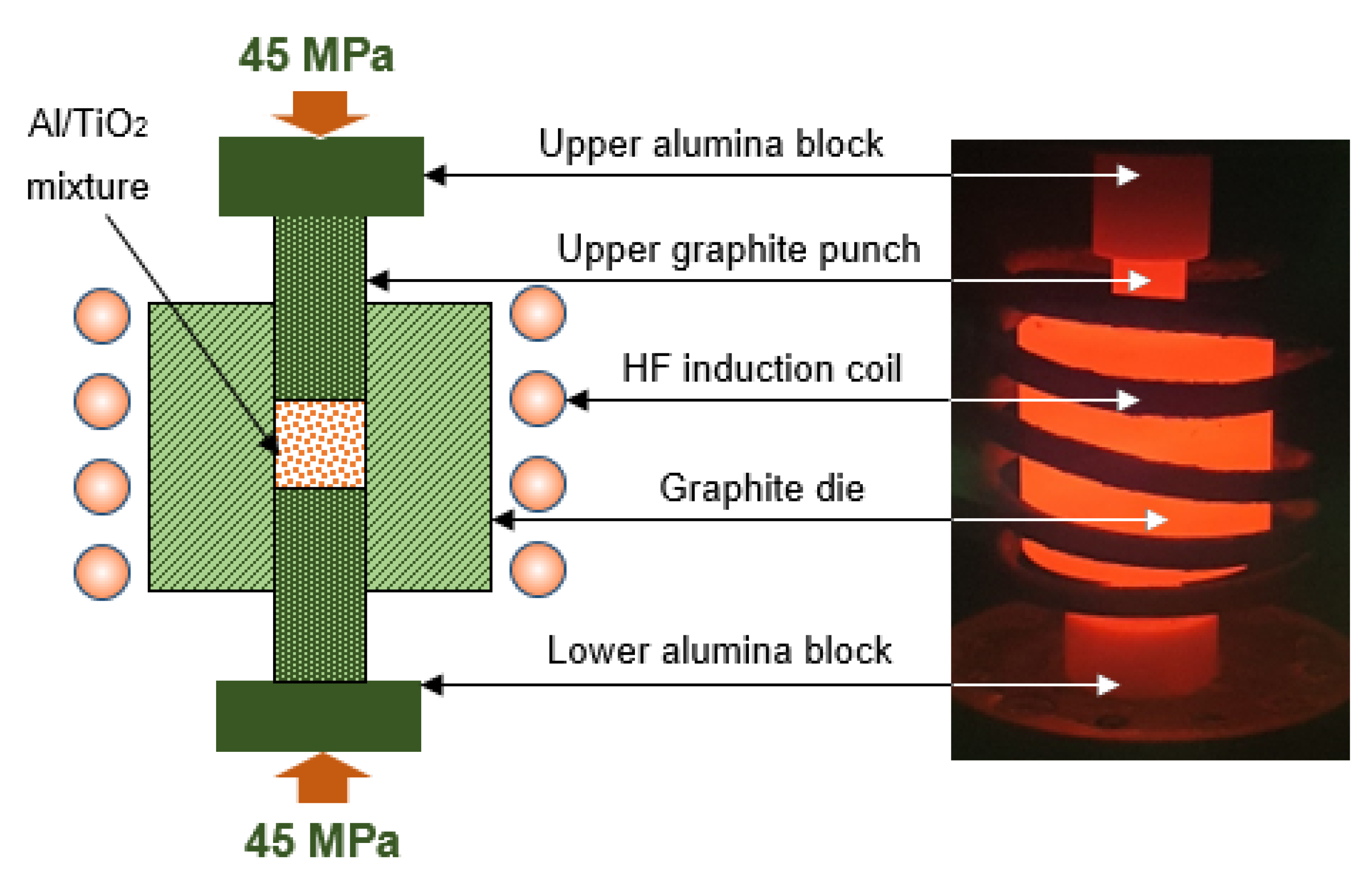
2.5. Sintering Process (Consolidation)

The milled powder mixture was inductively sintered using a high-frequency induction heat-sintering furnace (HFIHS Active Sinter System, ELTek Co., Gyeonggi-do, Korea). Three grams of nanocomposite mixture was loaded into a graphite die with 10 mm ID, 35 mm OD and 16 mm height (Figure 2) to produce a cylindrically shaped metal composite sample of 10 mm diameter and 12 mm height per run. Sintering was performed in a vacuumed atmosphere at 560 °C under 45 MPa axial pressure with a theating rate of 200 °C/min and 6 min holding time. Cooling after the consolidation process occurred spontaneously inside the furnace until reaching near room temperature.

2.6. Electrochemical Testing and Characterization

Electrochemical experiments and corrosion studies for the produced samples were performed using a Potentiostat Autolab (PGSTAT302N, Metrohm, Amsterdam, The Netherlands), and the test medium was 3.5% NaCl. A standard three-electrode electrochemical cell accommodating 30 mL of 3.5% NaCl solution was used. In this cell, the produced nanocomposites were used as the working electrode, an Ag/AgCl as reference electrode and a Platinum strip (Pt) as the auxiliary or counter electrodes. The EIS data were obtained at the open-circuit potential value, with frequencies ranging from 100 MHz to 100 mHz, by applying a −5 mV amplitude sinusoidal wave perturbation at the corrosion potential (ECorr). The cyclic potentiodynamic polarization (CPP) experiments were carried out by scanning the potential between −1600 mV and +100 mV (Ag/AgCl) with a scanning rate of 1.5 mV/s at room temperature. The tested surface area of all samples was the same and equal to π/4 (10 mm)2 ≅ 78.5 mm2. All samples were cleaned with acetone, then washed by distilled water and dried by air after being polished with emery paper and cloth-polished by alumina slurries before every test. Each test was repeated at least 3 times to ensure repeatability.
SEM micrographs and EDX investigations were conducted using a JEOL field emission scanning electron microscopy (FESEM) (model: JEOL JSM-7600F, Tokyo, Japan) with an energy-dispersive X-ray spectroscopy (EDS) unit from Oxford instruments attached. The chemical composition of the produced consolidated Al/TiO2 nanocomposite samples was obtained using an X-Ray diffraction pattern (XRD) (model: D8 discover from Bruker, Germany) with filtered Cu Kα radiation (λ = 1.5406 Å).

3. Results and Discussion

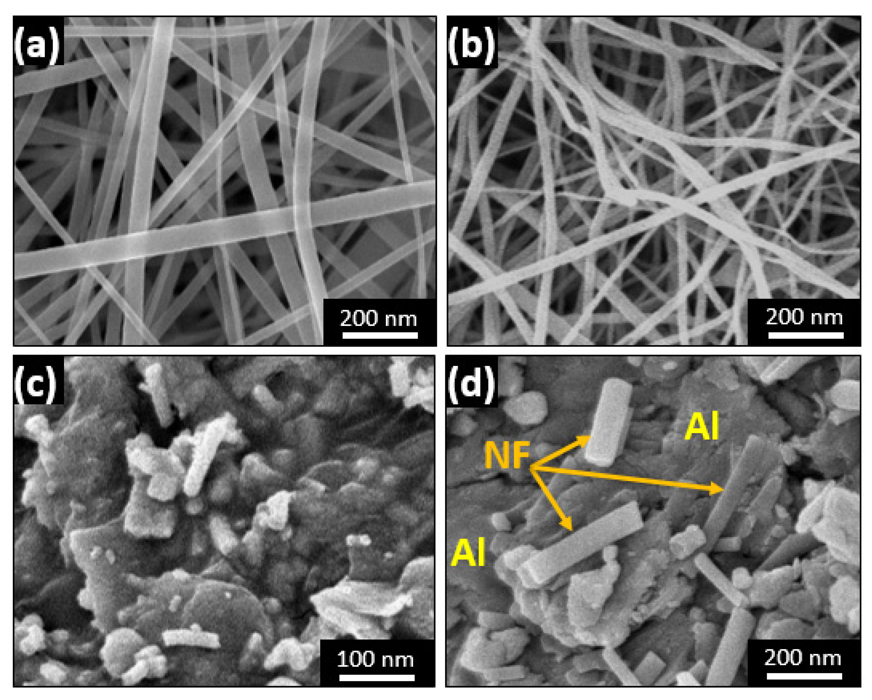
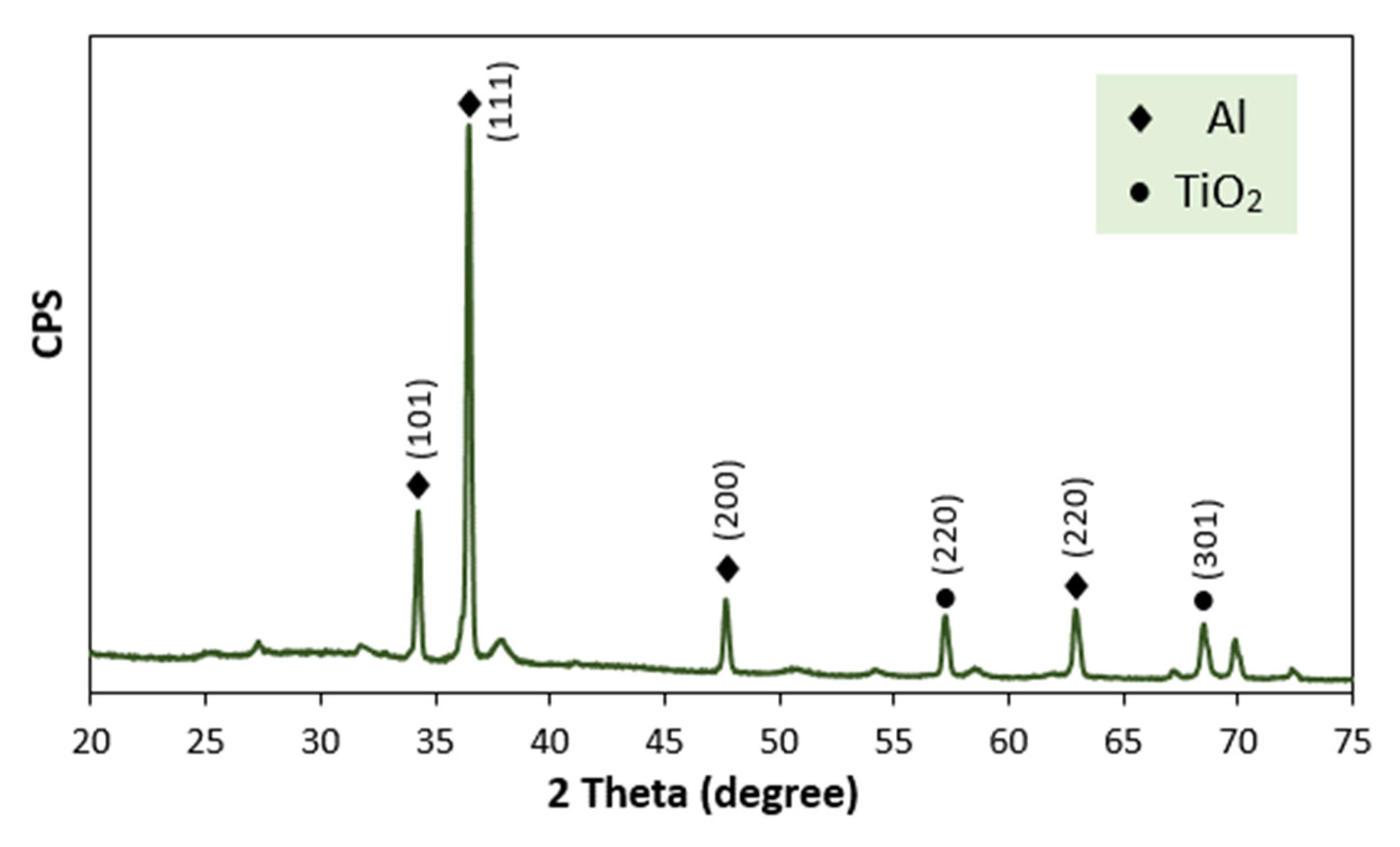
3.1. Ball-Milled Powder Morphology

The first and second steps of ceramic nanofiber reinforcement preparation is electrospinning of PVP/TiO2 sol-gel, followed by the calcination process. Figure 3a,b illustrate the produced nanofiber mat after electrospinning and after calcination, respectively. The average fiber diameter range is about 50–110 nm, with homogeneous and uniform structure and no defects. The change in nanofiber morphology following calcination consists mainly of some reduction in the diameter, with little distortion due to the evaporation of carbon during the high-temperature calcination process.
The morphology of the produced mixed powder of Al as the base matrix and the amount of the fabricated reinforcement of TiO2 ceramic nanofibers and their distribution can affect the electrochemical properties of the composites. Figure 3c,d illustrate the morphology of the mixture in the case of 5 wt.% ceramic nanofiber used in an Al matrix after complete mixing by ball milling for 1 h.
The chemical composition of the consolidated ball-milled mixed powders was investigated by XRD and is presented in Figure 4. The XRD diffraction peaks for the composite material Al/TiO2 is clear, and main peaks correspond to Al peaks, which are present at 2θ = 34, 37 and 62°, as long as the TiO2 nanofiber main peaks are at approximately 2θ = 57 and 68°.

3.2. Electrochemical Measurements

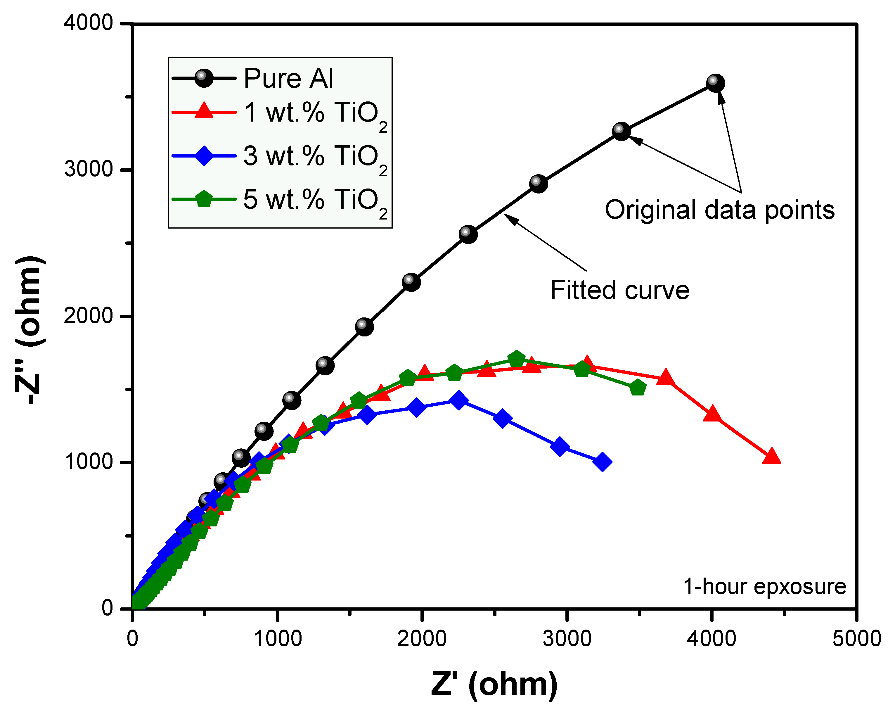
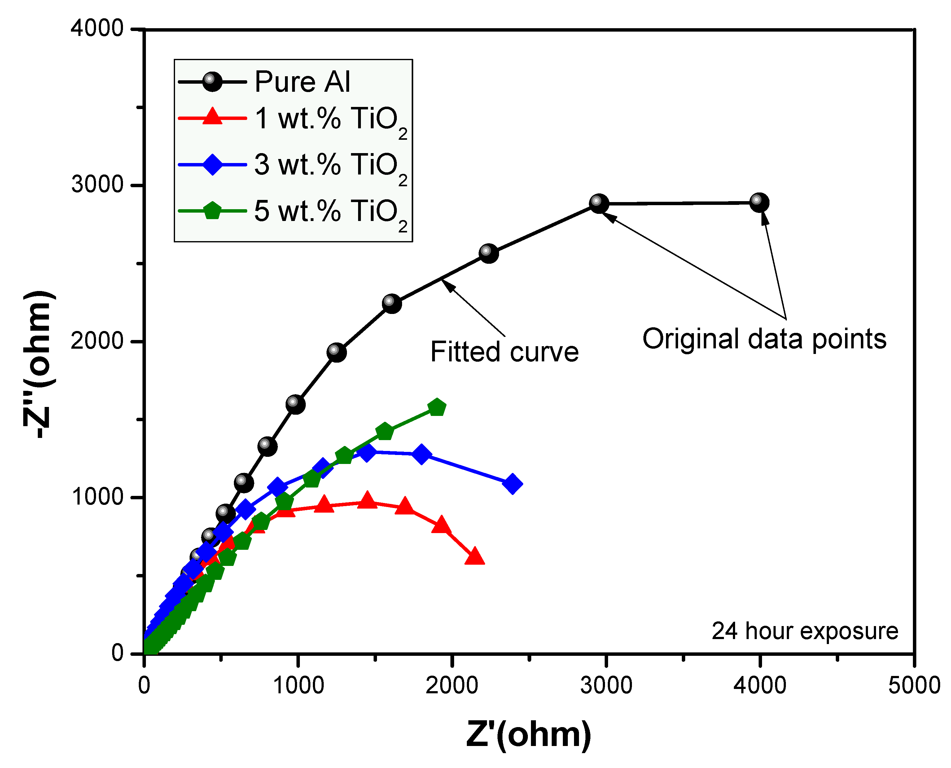
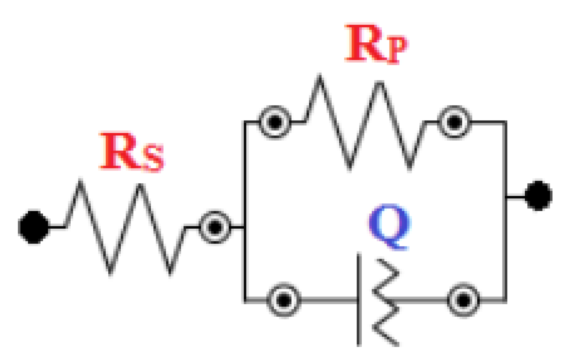
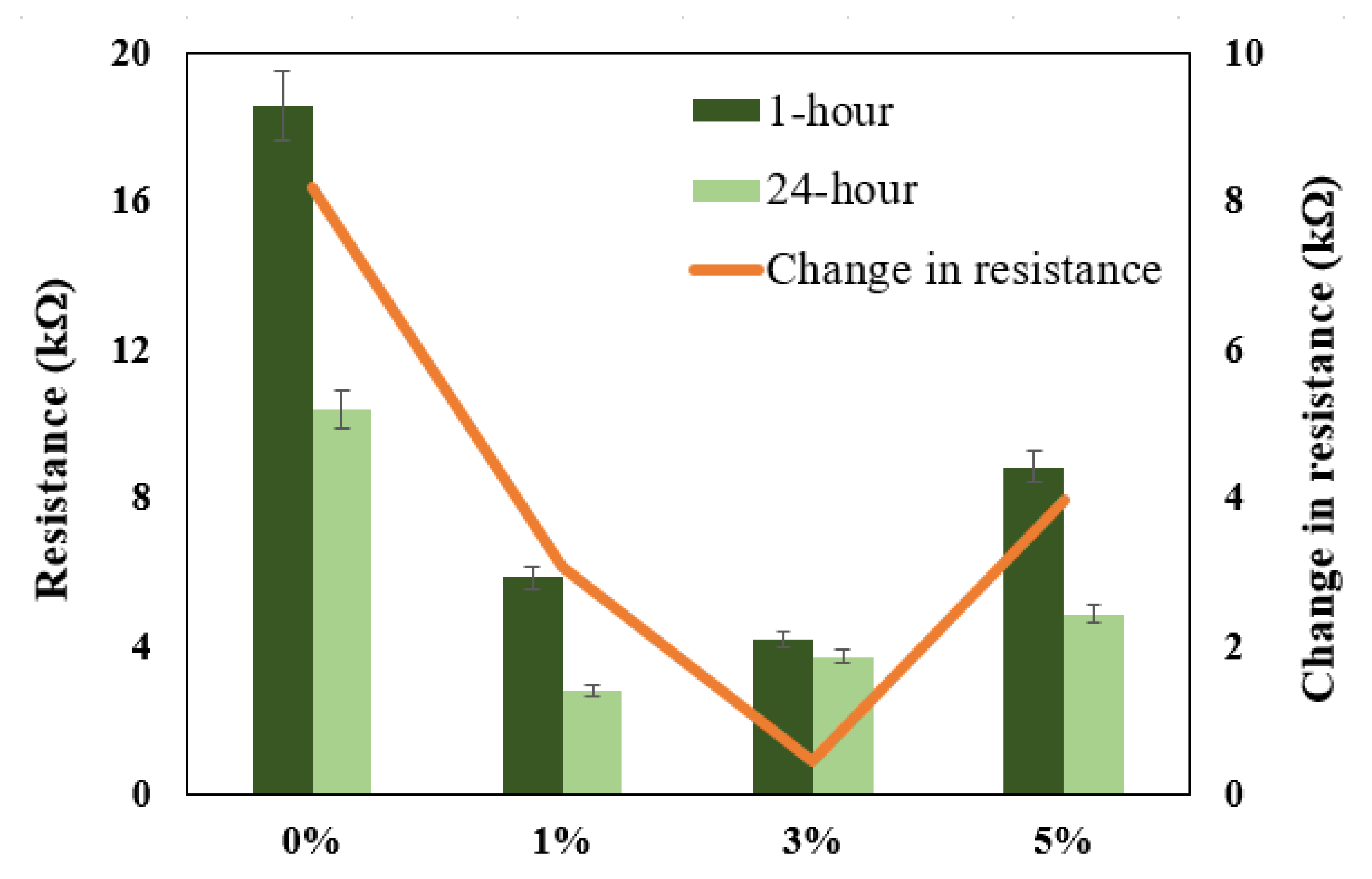
3.2.1. Electrochemical Impedance Spectroscopy (EIS)

In order to determine the anticorrosion properties of the prepared nanocomposites exposed to the aggressive environment of 3.5% NaCl solution, the EIS technique was employed [38,39,40,41,42]. Nyquist plots were obtained for the fabricated samples with compositions of 0, 1, 3 and 5 wt.% by varying their percentages for the immersion time of 1 h, as shown in Figure 5. The Nyquist plot obtained for the prolonged exposure period of 24 h for the same samples is shown in Figure 6. The fitting circuit used to fit the obtained graphs is shown in Figure 7, where Rs is the solution resistance; Rp is the polarization resistance, which can also be defined as charge-transfer resistance; and Q is the constant phase element (CPE). The results obtained by applying this circuit to fit are presented in Table 1.
It can be seen from Figure 5 and Figure 6, with exposure periods of 1 h and 24 h immersion results in 3.5% NaCl solution, that for all samples, there is only one distorted semicircle. With the increasing amount of TiO2 ceramic nanofibers as a reinforcement in the Al matrix, the semicircle becomes more depressed, and the diameter of the semicircle also decreases, which suggests that at the lower exposure time of 1-h, the prepared alloys have lower resistance to corrosion. It is generally agreed that the wider the diameter of the semicircle, the higher the corrosion resistance. The data obtained with the fitting circuit are shown in Table 1. The Rct value for all the alloys decreased with the inclusion of ceramic nanofibers, although the highest value of Rct was obtained with 5% inclusion when compared to all the prepared alloys, though still lower than the control sample without any ceramic fibers. The value of “n” in the CPE is in the range of 0.63 to 0.77 for the tests conducted on alloys, which represents CPE behaving like capacitance when the values of “n” happen to be in between 0 and 1. On the other hand, n = 0 represents pure resistance, n = 1 represents pure capacitance and n = 0.5 represents Warburg. In the case of our analysis, the results indicate that the surface is affected because of its exposure to NaCl solution. The values obtained for CPE decreased with the addition of ceramic nanofibers. With the increase in exposure time to 24-h, the results indicate a further decrease in diameter of all samples, which is due to the corrosion occurring on the alloy surface. Resistance against corrosion was found to decrease with the incorporation of ceramic TiO2 nanofibers, as the percentage of corrosion increased in comparison to the sample with no fibers. Figure 8 shows the resistances at exposure periods of both 1 h and 24 h in order to get an idea concerning the corrosion of alloys after the addition of ceramic fibers. It can be concluded from Figure 8 that addition of ceramic fibers deteriorates the anticorrosion properties of the prepared alloys, with even small-percentage changes making it more prone to corrosion. Although the difference between 1 h and 24 h resistance (Rct) for alloys prepared with 3% fibers is not significant compared to alloys, it it is still lower than for samples without any fibers. This is because Al undergoes corrosion with the formation of an oxide layer, which acts as passivation, therefore blocking further penetration of corrosive species. On the other hand, the addition of ceramic fibers to an Al matrix creates voids on the exposure surface, which have to be considered while taking up the surface area of the Al composite. These fiber-metal boundaries act as potential sites of attack by corrosive species, thus causing localized corrosion and making the material more prone to corrosion, which, in our case, resulted in deterioration of corrosion properties.

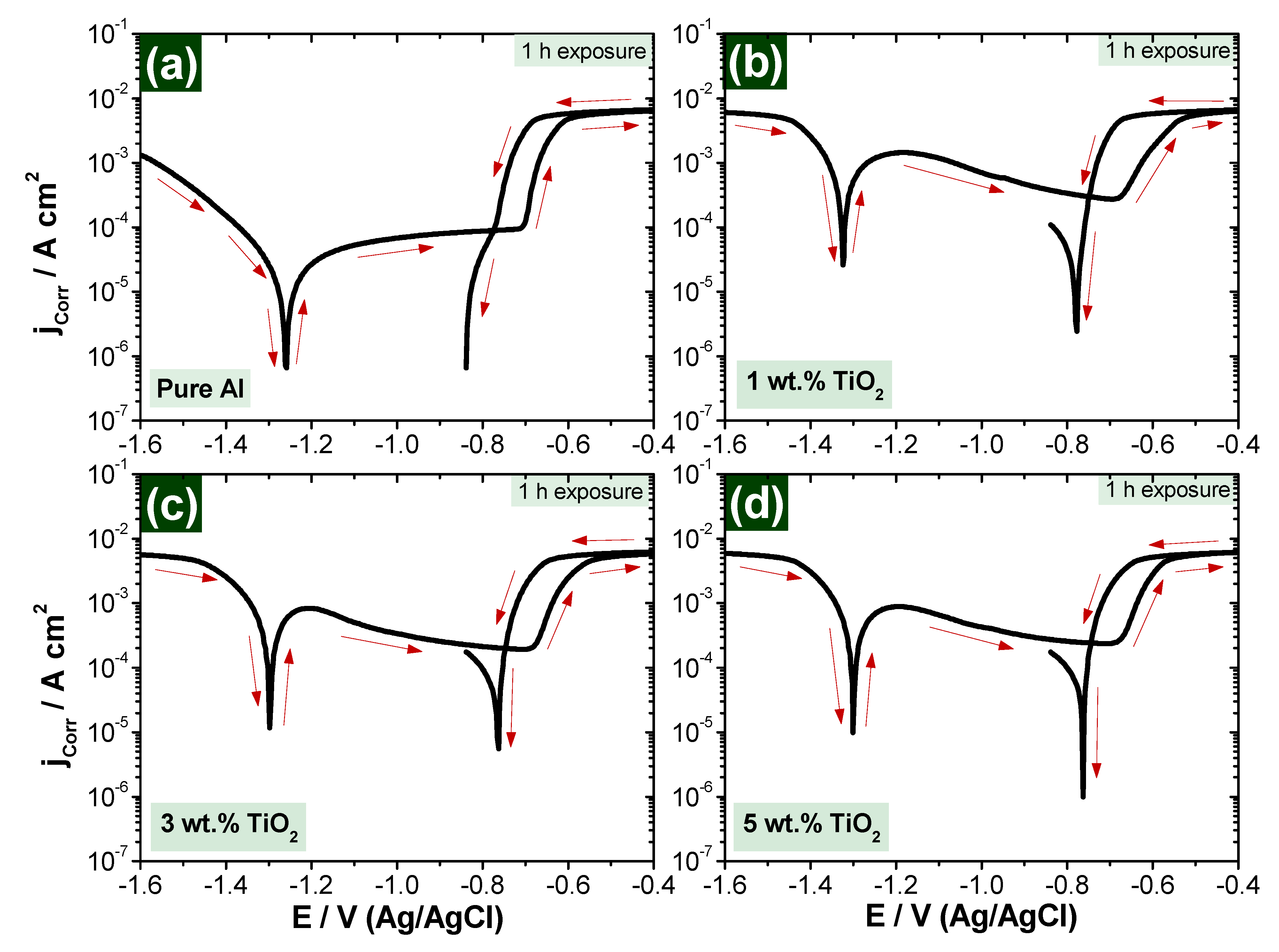
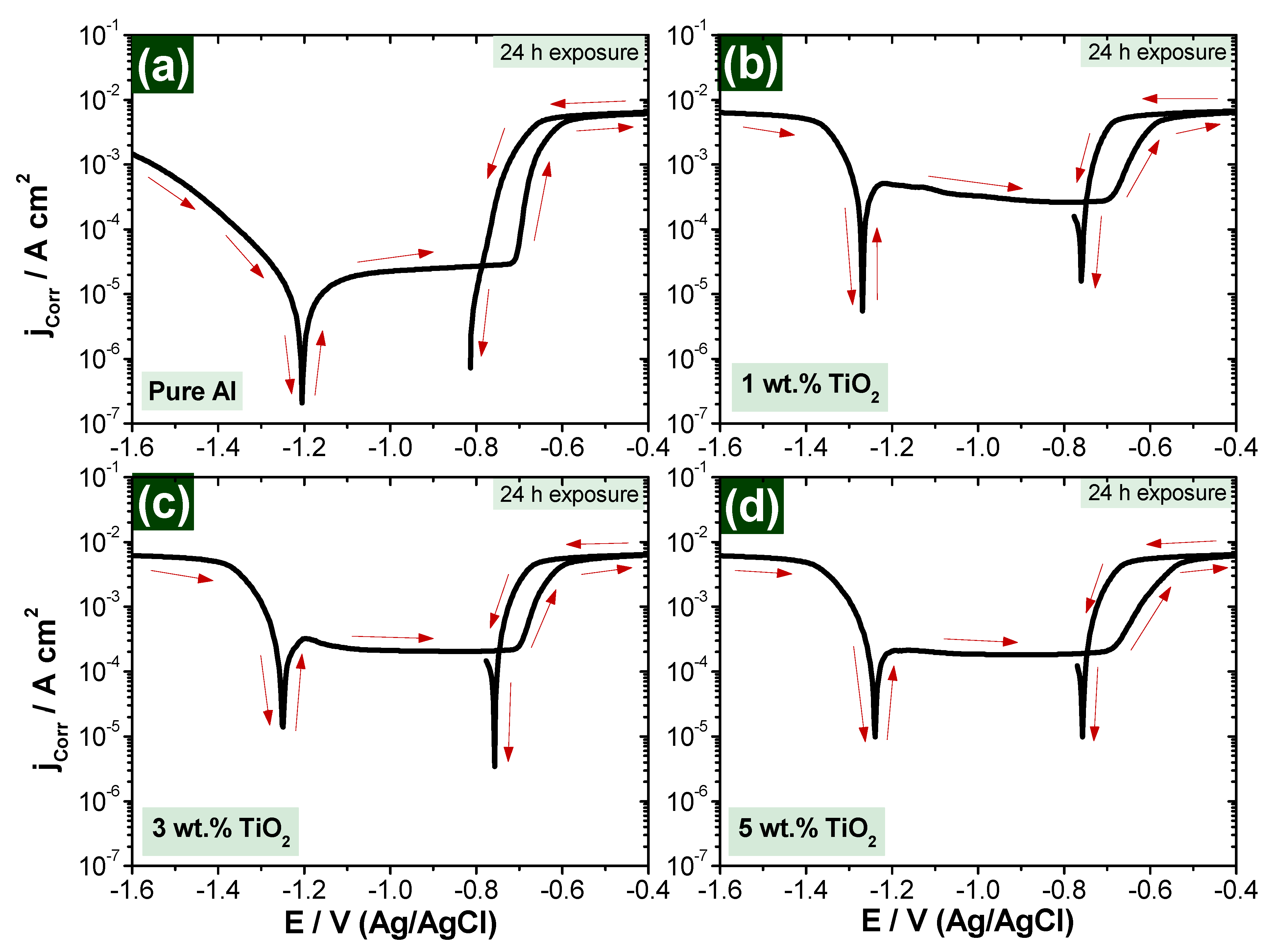
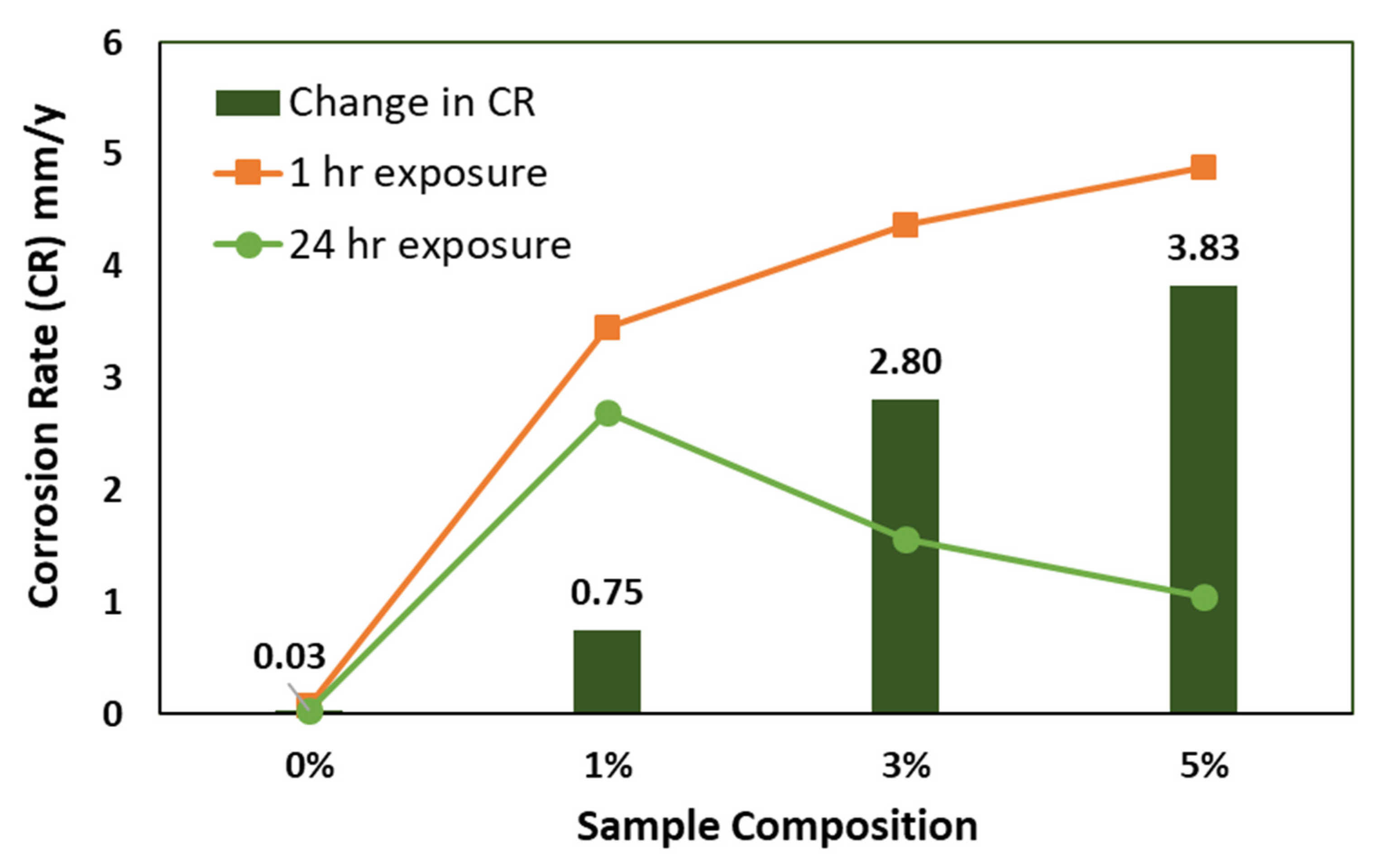
3.2.2. Cyclic Potentiodynamic Polarization (CPP)

The curves of Figure 9 and Figure 10 present the CPP measurements for the fabricated nanocomposite samples after immersion in 3.5% NaCl solution for 1 and 24 h, respectively. Table 2 is presents all values of the extracted parameters from CPP plots, such as polarization resistance (RP), corrosion rate (RCorr), corrosion current density (jCorr), corrosion potential (ECorr) and anodic and cathodic Tafel slopes (βa and βc). All parameters, including the corrosion rate, were calculated automatically by Autolab software (NOVA). Tafel slope was used to extract icorr and Ecorr from polarization data. The values were extracted by drawing anodic and cathodic slopes in the NOVA software, which then automatically calculated the values of icorr and Ecorr.
It is clearly shown from Figure 9 and Figure 10 that scanning the potential in the less negative direction leads to a decrease in the produced current in the cathodic portion due to the decrease in the rate of cathodic reaction of oxygen reduction at the more positive potentials [43,44,45], which helps to start the reaction of the cathode, followed by adsorption, according to Equation (1):
1 2 O 2 + H 2 O + 2 e = 2 OH
In anodic reaction, the corrosion takes place due to the dissolution reaction once the corrosive medium becomes available. In our case, Al is the active material to start the dissolution reaction on the sample surface, forming aluminum oxide (Al2O3) [46,47,48,49] and causing an increase in the anodic current [43,44,45], according to Equation (2):
Al   Al 3 + + 3 e
According to Equation (3), the rate of increase of the current in the anodic portion is slowed down by the application of the potential towards the less negative values due to the formation of oxide film Al2O3 [45] as follow:
3 OH + 2 Al surface = [ Al 2 O 3 ] adsorb + 3 e
Passivation of the fabricated nanocomposite sample surface is increased by increasing the reinforcement material, which is TiO2 in our study. The presence of TiO2 increases the passive region on the curves of the polarization measurements due to the reduction in the current values.
Polarization curves (Figure 9 and Figure 10) indicate that the change in corrosion rate between the immersion time of 1 h and 24 h samples in 3.5% NaCl solutions is decreased positively by increasing the reinforcement percentage, as presented in Figure 11.
From polarization curves, which are presented in Figure 9 and Figure 10, it can be concluded that the addition of ceramic nanofibers can increase resistance against corrosion in longer exposure periods, which is in agreement with the conclusion based on the impedance curves in Figure 5 and Figure 6.

4. Conclusions

Fabrication of Al/TiO2 nanocomposite reinforced by different percentages of ceramic nanofibers was achieved using powder metallurgy. Ceramic nanofibers were produced via electrospinning technique, followed by calcination at 750 °C. Al powder plus ceramic nanofibers were mixed together with different compositions using a high-energy ball milling technique at 100 rpm for 1 h. The homogeneous mixture was consolidated through an inductive sintering process at 560 °C and 45 MPa axial pressure with a heating rate of 200 °C/min and 6 min holding time. The fabricated nanocomposite samples were characterized, then electrochemically tested against corrosion. The effect of increasing the amount of ceramic nanofiber reinforcement from 0 wt.% up to 5 wt.% on corrosion behavior after 1 h and 24 h immersion in 3.5% NaCl solutions was reported. The investigations were carried out using different electrochemical techniques, namely electrochemical impedance spectroscopy and cyclic potentiodynamic polarization, along with characterization by methods such as FE-SEM and XRD. Electrochemical measurement results confirm that the addition of ceramic nanofibers to an Al matrix negatively affects its resistance against corrosion. On the other hand, the addition of ceramic nanofibers can increase resistance against corrosion for the same fabricated nanocomposite in longer exposure time periods. In a quantitative description, the enhancement of corrosion resistance for the 3 and 5 wt.% TiO2 reinforced sample can achieve to 65% and 75% amelioration, respectively by increasing the immersion period from 1 h to 24 h in 3.5% NaCl solution.

Author Contributions

Conceptualization, H.S.A.; methodology, H.S.A., U.A.S., M.S.A., H.I.A. and M.O.A.; software, M.S.A. and M.O.A.; validation, U.A.S., M.S.A., H.I.A. and M.O.A.; formal analysis, H.S.A., U.A.S., M.S.A., H.I.A. and M.O.A.; investigation, H.S.A. and U.A.S.; resources, H.S.A.; data curation, H.S.A., U.A.S., M.S.A., H.I.A. and M.O.A.; writing—original draft preparation, H.S.A.; writing—review and editing, H.S.A.; visualization, H.S.A., U.A.S., M.S.A., H.I.A. and M.O.A.; supervision, H.S.A.; project administration, H.S.A.; funding acquisition, H.S.A. and H.I.A. All authors have read and agreed to the published version of the manuscript.

Funding

This research was funded and supported by Taif University Researchers Supporting Project Number (TURSP-2020/264), Taif University, Taif, Saudi Arabia, and King Saud University, Deanship of Scientific Research, College of Engineering Research Center.

Institutional Review Board Statement

Not applicable.

Informed Consent Statement

Not applicable.

Data Availability Statement

Not applicable.

Acknowledgments

The authors would like to acknowledge the support from Taif University Researchers Supporting Project Number (TURSP-2020/264), Taif University, Taif, Saudi Arabia, and they extend their sincere appreciation to the King Saud University, Deanship of Scientific Research, College of Engineering Research Center for funding this research.

Conflicts of Interest

The authors declare no conflict of interest.

References

  1. Knight, M.; Curliss, D. Composite Materials, Encyclopedia of Physical Science and Technology, 3rd ed.; Academic Press: Cambridge, MA, USA, 2003; pp. 455–468. ISBN 9780122274107. [Google Scholar] [CrossRef]
  2. Haghshenas, M. Metal–Matrix Composites. Ref. Modul. Mater. Sci. Mater. Eng. 2016, 1, 1–28. [Google Scholar] [CrossRef]
  3. Norrell, T.; Ferguson, G.; Ansell, T.; Saladin, T.; Nardi, A.; Nieto, A. Synthesis and corrosion behavior of cold sprayed dual nanoparticle reinforced Al coatings. Surf. Coatings Technol. 2020, 401, 126280. [Google Scholar] [CrossRef]
  4. Suk, M.E. Effect of the Nanotube Radius and the Volume Fraction on the Mechanical Properties of Carbon Nanotube-Reinforced Aluminum Metal Matrix Composites. Molecules 2021, 26, 3947. [Google Scholar] [CrossRef] [PubMed]
  5. Chang, W.; Rose, L.R.F.; Islam, M.S.; Wu, S.; Peng, S.; Huang, F.; Kinloch, A.J.; Wang, C.H. Strengthening and toughening epoxy polymer at cryogenic temperature using cupric oxide nanorods. Compos. Sci. Technol. 2021, 208, 108762. [Google Scholar] [CrossRef]
  6. Abdo, H.S.; Khalil, K.A.; El-Rayes, M.M.; Marzouk, W.W.; Hashem, A.F.M.; Abdel-Jaber, G.T. Ceramic nanofibers versus carbon nanofibers as a reinforcement for magnesium metal matrix to improve the mechanical properties. J. King Saud Univ. Eng. Sci. 2020, 32, 346–350. [Google Scholar] [CrossRef]
  7. Abdo, H.S.; Mohammed, M.L.; Khalil, K.A. Fiber-reinforced metal-matrix composites. Fiber Reinf. Compos. 2021, 649–667. [Google Scholar] [CrossRef]
  8. Adebisi, A.A.; Maleque, M.A.; Rahman, M.M. Metal Matrix Composite Brake Rotors: Historical Development And Product Life Cycle Analysis. Int. J. Automot. Mech. Eng. 2011, 4, 471–480. [Google Scholar] [CrossRef]
  9. Abdo, H.S.; Seikh, A.H.; Fouly, A.; Ragab, S.A. Synergistic Strengthening Effect of Reinforcing Spark Plasma Sintered Al-Zn-TiC Nanocomposites with TiC Nanoparticles. Crystals 2021, 11, 842. [Google Scholar] [CrossRef]
  10. Kerti, I. Production of TiC reinforced-aluminum composites with the addition of elemental carbon. Mater. Lett. 2005, 59, 3795–3800. [Google Scholar] [CrossRef]
  11. Surappa, M.K. Aluminium matrix composites: Challenges and opportunities. Sadhana 2003, 28, 319–334. [Google Scholar] [CrossRef]
  12. Hansen, N. Strengthening of aluminium by a three-dimensional network of aluminium-oxide particles. Acta Metall. 1969, 17, 637–642. [Google Scholar] [CrossRef]
  13. Zhang, D.L.; Koch, C.C.; Scattergood, R.O. The role of new particle surfaces in synthesizing bulk nanostructured metallic materials by powder metallurgy. Mater. Sci. Eng. A 2009, 516, 270–275. [Google Scholar] [CrossRef]
  14. Montazeri, A.; Javadpour, J.; Khavandi, A.; Tcharkhtchi, A.; Mohajeri, A. Mechanical properties of multi-walled carbon nanotube/epoxy composites. Mater. Des. 2010, 31, 4202–4208. [Google Scholar] [CrossRef]
  15. Khalil, K.A.; Sherif, E.S.M.; Nabawy, A.M.; Abdo, H.S.; Marzouk, W.W.; Alharbi, H.F. Titanium Carbide Nanofibers-Reinforced Aluminum Compacts, a New Strategy to Enhance Mechanical Properties. Materials 2016, 9, 399. [Google Scholar] [CrossRef]
  16. Scudino, S.; Surreddi, K.B.; Sager, S.; Sakaliyska, M.; Kim, J.S.; Löser, W.; Eckert, J. Production and mechanical properties of metallic glass-reinforced Al-based metal matrix composites. J. Mater. Sci. 2008, 43, 4518–4526. [Google Scholar] [CrossRef]
  17. Lee, M.H.; Kim, J.H.; Park, J.S.; Kim, J.C.; Kim, W.T.; Kim, D.H. Fabrication of Ni–Nb–Ta metallic glass reinforced Al-based alloy matrix composites by infiltration casting process. Scr. Mater. 2004, 50, 1367–1371. [Google Scholar] [CrossRef]
  18. Dudina, D.V.; Georgarakis, K.; Li, Y.; Aljerf, M.; LeMoulec, A.; Yavari, A.R.; Inoue, A. A magnesium alloy matrix composite reinforced with metallic glass. Compos. Sci. Technol. 2009, 69, 2734–2736. [Google Scholar] [CrossRef]
  19. Slipenyuk, A.; Kuprin, V.; Milman, Y.; Goncharuk, V.; Eckert, J. Properties of P/M processed particle reinforced metal matrix composites specified by reinforcement concentration and matrix-to-reinforcement particle size ratio. Acta Mater. 2006, 54, 157–166. [Google Scholar] [CrossRef]
  20. Fouly, A.; Almotairy, S.M.; Aijaz, M.O.; Alharbi, H.F.; Abdo, H.S. Balanced Mechanical and Tribological Performance of High-Frequency-Sintered Al-SiC Achieved via Innovative Milling Route—Experimental and Theoretical Study. Crystals 2021, 11, 700. [Google Scholar] [CrossRef]
  21. Abdo, H.S.; Khalil, K.A.; El-Rayes, M.M.; Marzouk, W.W.; Hashem, A.M.; Abdel-Jaber, G.T. Electrospun Nanofibers Reinforced Aluminium Matrix Composites, A Trial to Improve the Mechanical Properties. Mech. Prop. Int. J. Adv. Mater. Sci. Eng. 2018, 7. [Google Scholar] [CrossRef]
  22. Karim, M.R.; Al-Ahmari, A.; Dar, M.A.; Aijaz, M.O.; Mollah, M.L.; Ajayan, P.M.; Yeum, J.H.; Kim, K.-S. Conducting and Biopolymer Based Electrospun Nanofiber Membranes for Wound Healing Applications. Curr. Nanosci. 2016, 12, 220–227. [Google Scholar] [CrossRef]
  23. Aijaz, M.O.; Karim, M.R.; Alharbi, H.F.; Alharthi, N.H. Novel optimised highly aligned electrospun PEI-PAN nanofibre mats with excellent wettability. Polymer 2019, 180, 121665. [Google Scholar] [CrossRef]
  24. Aijaz, M.O.; Karim, M.R.; Alharbi, H.F.; Alharthi, N.H.; Al-Mubaddel, F.S.; Abdo, H.S. Magnetic/Polyetherimide-Acrylonitrile Composite Nanofibers for Nickel Ion Removal from Aqueous Solution. Membranes 2021, 11, 50. [Google Scholar] [CrossRef] [PubMed]
  25. Li, Z.; Liu, S.; Song, S.; Xu, W.; Sun, Y.; Dai, Y. Porous ceramic nanofibers as new catalysts toward heterogeneous reactions. Compos. Commun. 2019, 15, 168–178. [Google Scholar] [CrossRef]
  26. Zhao, W.; Yang, F.; Liu, Z.; Chen, H.; Shao, Z.; Zhang, X.; Wang, K.; Xue, L. A novel (La0.2Sm0.2Eu0.2Gd0.2Tm0.2)2Zr2O7 high-entropy ceramic nanofiber with excellent thermal stability. Ceram. Int. 2021, 47, 29379–29385. [Google Scholar] [CrossRef]
  27. Neubauer, E.; Kitzmantel, M.; Hulman, M.; Angerer, P. Potential and challenges of metal-matrix-composites reinforced with carbon nanofibers and carbon nanotubes. Compos. Sci. Technol. 2010, 70, 2228–2236. [Google Scholar] [CrossRef] [Green Version]
  28. He, L.; Pan, L.; Li, W.; Dong, Q.; Sun, W. Spectral response characteristics of Eu3+ doped YAG-Al2O3 composite nanofibers reinforced aluminum matrix composites. Opt. Mater. 2020, 104, 109845. [Google Scholar] [CrossRef]
  29. Almotairy, S.M.; Alharthi, N.H.; Abdo, H.S. Regulating Mechanical Properties of Al/SiC by Utilizing Different Ball Milling Speeds. Crystals 2020, 10, 332. [Google Scholar] [CrossRef]
  30. Almotairy, S.M.; Alharthi, N.H.; Alharbi, H.F.; Abdo, H.S. Superior Mechanical Performance of Inductively Sintered Al/SiC Nanocomposites Processed by Novel Milling Route. Sci. Rep. 2020, 10, 10368. [Google Scholar] [CrossRef] [PubMed]
  31. Khalil, K.A.; Almajid, A.A. Effect of high-frequency induction heat sintering conditions on the microstructure and mechanical properties of nanostructured magnesium/hydroxyapatite nanocomposites. Mater. Des. 2012, 36, 58–68. [Google Scholar] [CrossRef]
  32. Yang, Q.; Liu, J.; Li, S.; Wang, F.; Wu, T. Fabrication and mechanical properties of Cu-coatedwoven carbon fibers reinforced aluminum alloy composite. Mater. Des. 2014, 57, 442–448. [Google Scholar] [CrossRef]
  33. Sha, J.J.; Lü, Z.Z.; Sha, R.Y.; Zu, Y.F.; Dai, J.X.; Xian, Y.Q.; Zhang, W.; Cui, D.; Yan, C.L. Improved wettability and mechanical properties of metal coated carbon fiber-reinforced aluminum matrix composites by squeeze melt infiltration technique. Trans. Nonferrous Met. Soc. China 2021, 31, 317–330. [Google Scholar] [CrossRef]
  34. Kang, S.; Hou, S.; Chen, X.; Yu, D.G.; Wang, L.; Li, X.; Williams, G.R. Energy-Saving Electrospinning with a Concentric Teflon-Core Rod Spinneret to Create Medicated Nanofibers. Polymers 2020, 12, 2421. [Google Scholar] [CrossRef]
  35. He, H.; Wu, M.; Zhu, J.; Yang, Y.; Ge, R.; Yu, D.-G. Engineered Spindles of Little Molecules Around Electrospun Nanofibers for Biphasic Drug Release. Adv. Fiber Mater. 2021, 1–13. [Google Scholar] [CrossRef]
  36. Li, D.; Wang, M.; Song, W.-L.; Yu, D.-G.; Wan, S.; Bligh, A.; Li, D.; Wang, M.; Song, W.-L.; Yu, D.-G.; et al. Electrospun Janus Beads-On-A-String Structures for Different Types of Controlled Release Profiles of Double Drugs. Biomolecules 2021, 11, 635. [Google Scholar] [CrossRef] [PubMed]
  37. Alharbi, H.F.; Haddad, M.Y.; Aijaz, M.O.; Assaifan, A.K.; Karim, M.R. Electrospun Bilayer PAN/Chitosan Nanofiber Membranes Incorporated with Metal Oxide Nanoparticles for Heavy Metal Ion Adsorption. Coatings 2020, 10, 285. [Google Scholar] [CrossRef] [Green Version]
  38. Abdo, H.S.; Seikh, A.H.; Fouly, A.; Hashmi, F.H. Controlling Atmospheric Corrosion of Weathering Steel Using Anodic Polarization Protection Technique. Processes 2021, 9, 1469. [Google Scholar] [CrossRef]
  39. Abdo, H.S.; Samad, U.A.; Mohammed, J.A.; Ragab, S.A.; Seikh, A.H. Mitigating Corrosion Effects of Ti-48Al-2Cr-2Nb Alloy Fabricated via Electron Beam Melting (EBM) Technique by Regulating the Immersion Conditions. Crystals 2021, 11, 889. [Google Scholar] [CrossRef]
  40. Abdo, H.S.; Seikh, A.H.; Mohammed, J.A.; Uzzaman, T. Ameliorative Corrosion Resistance and Microstructure Characterization of 2205 Duplex Stainless Steel by Regulating the Parameters of Pulsed Nd:YAG Laser Beam Welding. Metals 2021, 11, 1206. [Google Scholar] [CrossRef]
  41. Abdo, H.S.; Sarkar, A.; Gupta, M.; Sahoo, S.; Mohammed, J.A.; Ragab, S.A.; Seikh, A.H. Low-Cost High-Performance SnO2–Cu Electrodes for Use in Direct Ethanol Fuel Cells. Crystals 2021, 11, 55. [Google Scholar] [CrossRef]
  42. Abdo, H.S.; Seikh, A.H.; Mandal, B.B.; Mohammed, J.A.; Ragab, S.A.; Abdo, M.S. Microstructural Characterization and Corrosion-Resistance Behavior of Dual-Phase Steels Compared to Conventional Rebar. Crystals 2020, 10, 1068. [Google Scholar] [CrossRef]
  43. Mazhar, A.A.; Badawy, W.A.; Abou-Romia, M.M. Impedance studies of corrosion resistance of aluminium in chloride media. Surf. Coatings Technol. 1986, 29, 335–345. [Google Scholar] [CrossRef]
  44. Badawy, W.A.; Al-Kharafi, F.M.; El-Azab, A.S. Electrochemical behaviour and corrosion inhibition of Al, Al-6061 and Al-Cu in neutral aqueous solutions. Corros. Sci. 1999, 41, 709–727. [Google Scholar] [CrossRef]
  45. Tomcsányi, L.; Varga, K.; Bartik, I.; Horányi, H.; Maleczki, E. Electrochemical study of the pitting corrosion of aluminium and its alloys-II. Study of the interaction of chloride ions with a passive film on aluminium and initiation of pitting corrosion. Electrochim. Acta 1989, 34, 855–859. [Google Scholar] [CrossRef]
  46. Liew, Y.; Örnek, C.; Pan, J.; Thierry, D.; Wijesinghe, S.; Blackwood, D.J. Towards understanding micro-galvanic activities in localised corrosion of AA2099 aluminium alloy. Electrochim. Acta 2021, 392, 139005. [Google Scholar] [CrossRef]
  47. Selvamani, S.T. Microstructure and stress corrosion behaviour of CMT welded AA6061 T-6 aluminium alloy joints. J. Mater. Res. Technol. 2021, 15, 315–326. [Google Scholar] [CrossRef]
  48. Zhou, B.; Liu, B.; Zhang, S.; Lin, R.; Jiang, Y.; Lan, X. Microstructure evolution of recycled 7075 aluminum alloy and its mechanical and corrosion properties. J. Alloys Compd. 2021, 879, 160407. [Google Scholar] [CrossRef]
  49. Xiao, W.; Wang, Y. Corrosion resistance of aluminum fluoride modified 6061 aluminum alloy. Mater. Lett. 2021, 298, 129932. [Google Scholar] [CrossRef]
Figure 1. Schematic layout for the electrospinning device employed.
Polymers 13 04319 g001
Figure 2. Graphite die setup used for sintering/consolidation process.
Polymers 13 04319 g002
Figure 3. SEM images for (a) PVP/TiO2 nanofiber mat before calcination, (b) TiO2 nanofiber after calcination, (c,d) Al/TiO2 powder mixture at different magnifications.
Polymers 13 04319 g003
Figure 4. XRD of the 5 wt.% Al/TiO2 consolidated sample.
Polymers 13 04319 g004
Figure 5. EIS for composite samples exposed for 1-h in 3.5% NaCl solution.
Polymers 13 04319 g005
Figure 6. EIS for composite samples exposed for 24-h in 3.5% NaCl solution.
Polymers 13 04319 g006
Figure 7. Equivalent circuit used for Nyquist plot analysis.
Polymers 13 04319 g007
Figure 8. Graphical representation of Rct obtained after 1 h and 24 h exposure to NaCl solution.
Polymers 13 04319 g008
Figure 9. CPP for composite samples exposed for 1-h in 3.5% NaCl solution (a) Pure Al, (b) 1 wt.% TiO2, (c) 3 wt.% TiO2 and (d) 5 wt.% TiO2.
Polymers 13 04319 g009
Figure 10. CPP for composite samples exposed for 24-h in 3.5% NaCl solution (a) Pure Al, (b) 1 wt.% TiO2, (c) 3 wt.% TiO2 and (d) 5 wt.% TiO2.
Polymers 13 04319 g010
Figure 11. Graphical representation of corrosion rate (CR) after 1 h and 24 h exposure to NaCl solution.
Polymers 13 04319 g011
Table 1. Obtained parameters after EIS experiment on the composite samples with exposures of 1 h and 24 h in 3.5% NaCl solutions.
SampleTimeRct (k.ohm)Q
Y0 (µMho)n
Pure Al1-h18,6002040.63
1 wt.% TiO2587070.10.65
3 wt.% TiO241701090.73
5 wt.% TiO288601800.67
Pure Al24-h10,4002030.71
1 wt.% TiO227901180.77
3 wt.% TiO237301840.70
5 wt.% TiO248702500.69
Table 2. Obtained parameters of the composite samples from CPP plots with exposures of 1-h and 24-h in 3.5% NaCl solutions.
SampleParameter
βa/mV·dec−1βc/mV·dec−1ECorr/VjCorr/µA·cm−2Rp/kΩ·cm2RCorr/mmpy
1 hPure Al0.0740070.059014−1.25945.732.49010.06654
1 wt.% TiO20.106860.056606−1.3231296.750.0541553.4482
3 wt.% TiO20.207040.10647−1.2967375.900.0812334.3679
5 wt.% TiO20.234710.10866−1.2992419.990.0768074.8803
24 hPure Al0.0667610.07771−1.20383.124.9920.036303
1 wt.% TiO20.104590.057999−1.2683232.210.0697792.6983
3 wt.% TiO20.0526220.1107−1.2497134.540.115141.5633
5 wt.% TiO20.0512070.057243−1.239690.730.129381.0542
Publisher’s Note: MDPI stays neutral with regard to jurisdictional claims in published maps and institutional affiliations.

