Article

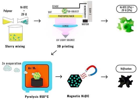
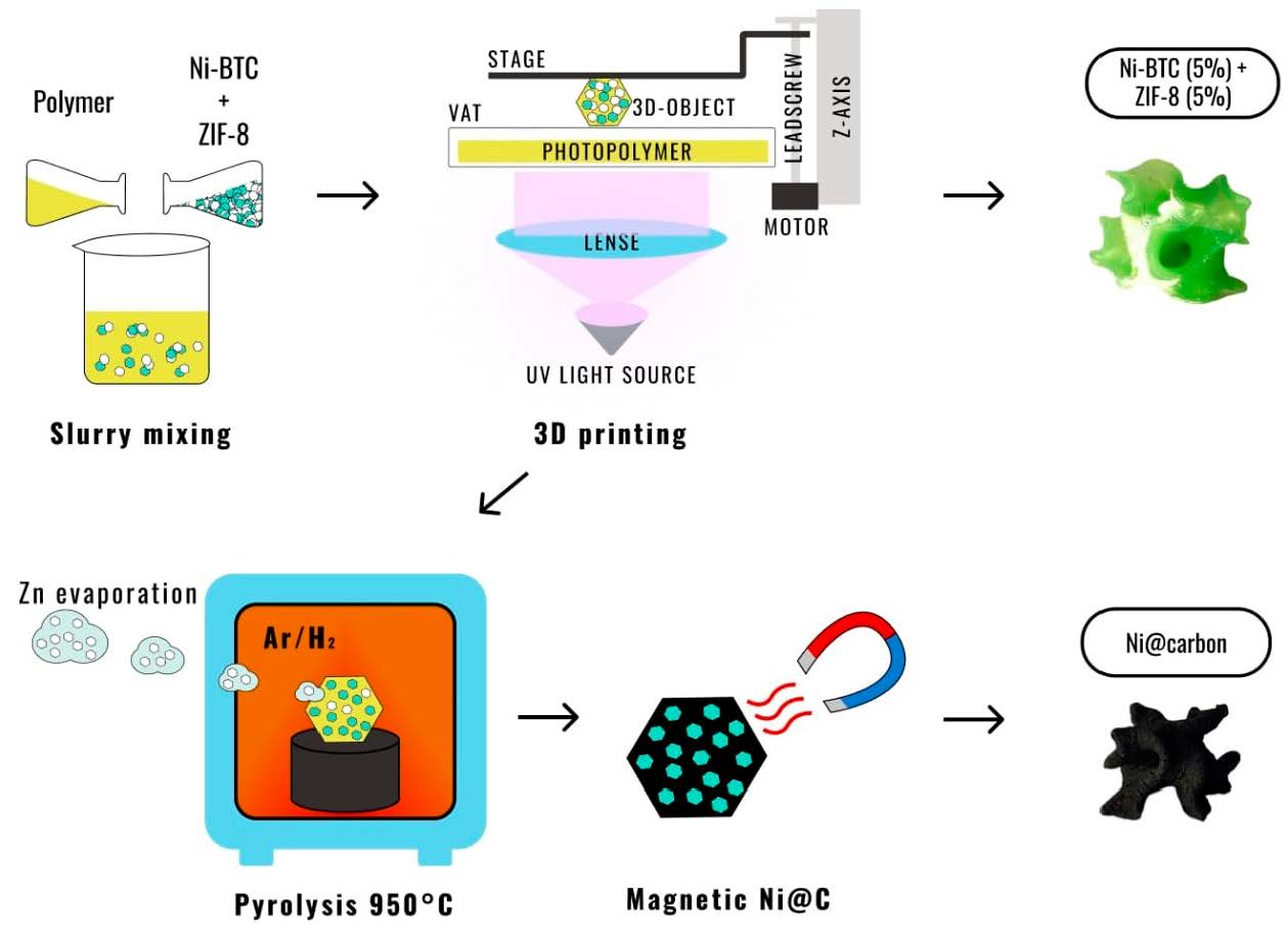
3D-Printed Porous Magnetic Carbon Materials Derived from Metal–Organic Frameworks

by
Anton I. Cherevko
1,2,
Igor A. Nikovskiy
1,
Yulia V. Nelyubina
1,2,
Kirill M. Skupov
1,
Nikolay N. Efimov
3 and
Valentin V. Novikov
1,2,*
1
A.N. Nesmeyanov Institute of Organoelement Compounds, Russian Academy of Sciences, 119991 Moscow, Russia
2
Moscow Institute of Physics and Technology, 141700 Dolgoprudny, Russia
3
Kurnakov Institute of General and Inorganic Chemistry, Russian Academy of Sciences, 119991 Moscow, Russia
*
Author to whom correspondence should be addressed.
Polymers 2021, 13(22), 3881; https://doi.org/10.3390/polym13223881
Submission received: 25 October 2021 / Revised: 6 November 2021 / Accepted: 8 November 2021 / Published: 10 November 2021
(This article belongs to the Special Issue 3D Printing of Functional Polymer Composites)

Abstract

:
Here we report new porous carbon materials obtained by 3D printing from photopolymer compositions with zinc- and nickel-based metal–organic frameworks, ZIF-8 and Ni-BTC, followed by high-temperature pyrolysis. The pyrolyzed materials that retain the shapes of complex objects contain pores, which were produced by boiling zinc and magnetic nickel particles. The two thus provided functionalities—large specific surface area and ferromagnetism—that pave the way towards creating heterogenous catalysts that can be easily removed from reaction mixtures in industrial catalytic processes.

Graphical Abstract

1. Introduction

Today, 3D printing, an additive manufacturing (AM) technique, has gone far beyond prototyping of industrial products [1]. It is now used to transform digital models into real-world objects for applications in catalysis [2], medicine [3], gas adsorption and storage [4,5], etc. [6] by layer-by-layer deposition of a polymer [7]. Of the many 3D printing processes [8], the most popular are polymer extrusion (fused deposition modeling, FDM, or directly ink writing, DIW) [9,10] and vat polymerization (stereolithography, SLA, or digital light processing, DLP) [11]. They can both produce functionalized objects from composite materials [12] containing the polymer matrix with a filler that provides the needed functionality. Inorganic nanoparticles may be added to increase the catalytic activity of the 3D-printed objects [13], such as zeolites and metal–organic frameworks, to increase their adsorption characteristics [14], and graphene, to improve their electrical conductivity [15].
Such a simple approach to creating active objects, however, suffers from a blocking of the filler by the polymer matrix that prevents it from performing its functions [16]. Possible ways of overcoming this drawback include functionalization of the objects after the 3D printing process [17] or heat dissolution of the polymer matrix to remove the binder and thereby obtain 3D-printed objects [18] with new, emergent properties.
Sometimes chosen as fillers in composite materials for 3D printing [19], metal–organic frameworks (MOFs) are porous crystalline solids made of metal ions or its clusters and organic linkers [20]. Their high surface area, tunable pore size and other engineerable properties [21] make them useful in gas separation and storage [22,23], heterogenous catalysis [24], medicine [25], sensors [26], etc. [27]. On the other hand, their low mechanical strength and poor chemical and thermal stability [28] prompt the researchers to incorporate MOFs into various composite materials, such as those for 3D printing applications [29,30,31,32]. Of particular interest are porous carbon materials obtained by their pyrolysis [33]. The MOF-based carbon materials with distributed nanoparticles of metal, metal carbide or metal oxide [34,35] feature high thermal, chemical and mechanical stability as nanotubes (CNTs) [36,37], nanowires [38], etc. Together with a large specific surface area and an adjustable pore structure [39] that allows encapsulating various compounds [40], they are finding use in catalysis [41], gas storage [42], etc. [43,44]. Nevertheless, the pyrolyzed MOFs are rather brittle, so they are very difficult to mold [45].
Here, we report a porous MOF-based carbon material doped with nickel particles that has a complex geometry obtained by stereolithography (SLA) 3D printing from a photopolymer composition containing two popular MOFs, Ni-BTC [46] and ZIF-8 [47], as functionalizing fillers and so the material can be potentially applied as a nickel-based catalyst [48].

2. Materials and Methods
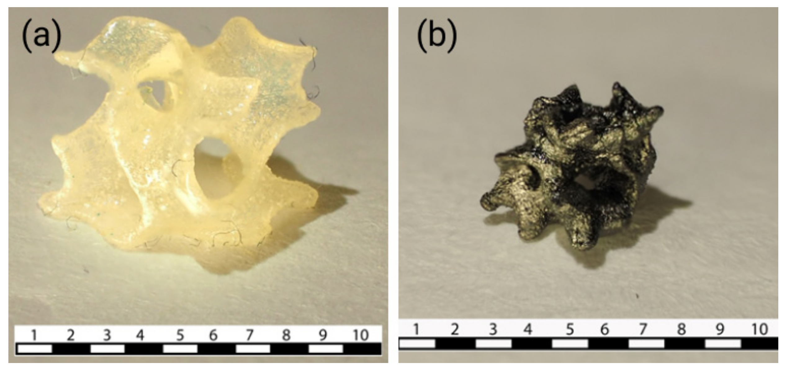
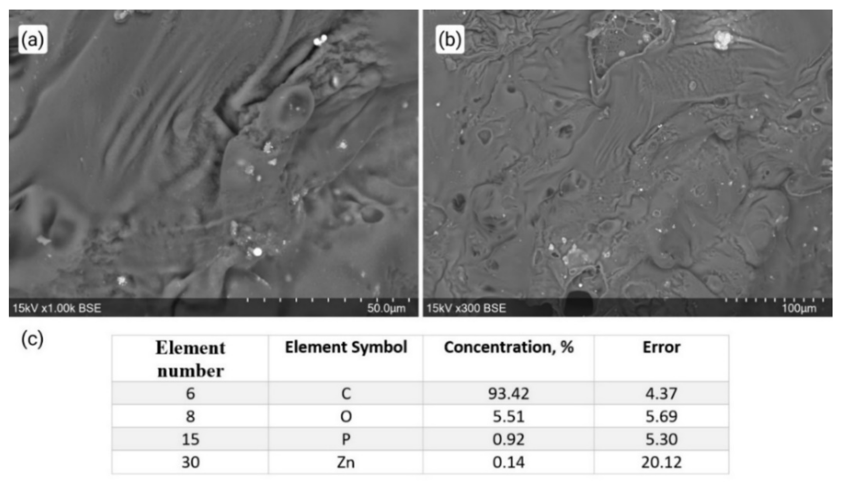
Synthesis. All synthetic manipulations were carried out in air unless stated otherwise. Solvents were purchased from commercial sources and purified by distilling from conventional drying agents under an argon atmosphere prior to use. 2-Phenoxyethyl acrylate (Sartomer SR-339, C11H12O3), bis(2,4,6-trimethylbenzoyl)-phenylphosphineoxide (Irgacure 819) and 1-hydroxy-cyclohexyl-phenyl-ketone (Irgacure 184) were purchased from Sigma-Aldrich (St. Louis, MO, USA); stabilized trimethylolpropane triacrylate (TMPTA, C15H20O6) from Alfa Aesar (Kandel, Germany) and resin HARZ Labs Model Resin, from HARZ Labs (Russia). ZIF-8 and Ni-BTC were obtained using synthetic approaches adopted from [46,47].
ZIF-8: A solution of Zn(NO3)2•6H2O (2.93 g, 9.87 mmol) in 200 mL of methanol was quickly added to a solution of 2-methylimidazole (6.489 g, 79.04 mmol) in 200 mL of methanol. The reaction mixture was stirred at room temperature for 1.5 h, and the resulting suspension was centrifuged at 6000 rpm for 5 min. The precipitate was washed with DMF and three times with methanol to exclude residues of 2-methylimidazole. The obtained crystalline product was dried under vacuum. Yield: 0.435 g (19.37%). Calculated for C48H60N24Zn6 (%): C, 42.22; H, 4.43; N, 24.62. Found (%): C, 42.29; H, 4.46; N, 24.67.
Ni-BTC: Ni(OAc)2•2H2O (3 g, 5.16 mmol) was dissolved in 100 mL solution of water, ethanol and DMF (1:1:1) at room temperature. A solution of trimesic acid (1.08 g, 5.16 mmol) in 100 mL of the same solvent mixture was added. The reaction mixture was stirred at room temperature for 2 h, and the resulting suspension was filtered, washed three times with DMF and three times with methylene chloride and was then immersed in methylene chloride. The solvent was decanted and replaced once per day over the next three days. The obtained crystalline product was dried under vacuum. Yield: 1.74 g (41.8%). Calculated for C18H30O24Ni3 (%): C, 26.80; H, 3.75. Found (%): C, 26.74; H, 3.63.
Photocurable resin preparation. 2-Phenoxyethyl acrylate (2.35 g) and trimethylolpropane triacrylate (2.35 g) were mixed with 2.4 wt.% of bis(2,4,6-trimethylbenzoyl)-phenylphosphineoxide and 4.8 wt.% of 1-hydroxy-cyclohexyl-phenyl-ketone in a polypropylene cup.
ZIF-8@polymer: ZIF-8 (5 wt.%) was incrementally added to the resulting resin until the desired loading level was reached, and the mixture was sonicated with a tip-sonicator (UZD2-0.1/22, Russia) for 5–10 min and at 50% amplitude to produce a homogeneous dispersion.
Ni-BTC+ZIF-8@polymer: Ni-BTC (5 wt.%) and ZIF-8 (5 wt.%) were incrementally added to the resulting resin until the desired loading level was reached, and the mixture was sonicated with a tip-sonicator (UZD2-0.1/22, Russia) for 5–10 min and at 50% amplitude to produce a homogeneous dispersion.
Ni-BTC+ZIF-8@HARZ Labs: Ni-BTC (5 wt.%) and ZIF-8 (5 wt.%) were incrementally added to the commercial photopolymer resin HARZ Labs Model LCD/DLP until the desired loading level was reached, and the resulting mixture was sonicated with a tip-sonicator (UZD2-0.1/22, Russia) for 5–10 min and at 50% amplitude to produce a homogeneous dispersion.
3D printing. Stereolithography was performed with a DLP/LCD/SLA 3D printer DUPLICATOR 7 PLUS (Wanhao, China) equipped with a reduced-size working bath. Creation Workshop software (1.0.0.75) was used for slicing and creating G-code files. The layer thickness was set to 100 μm, and the exposure time of the base layer was 5 s and of five initial layers, 100 s.
Pyrolysis. 3D-printed objects were washed with isopropyl alcohol and then pyrolyzed in a tubular furnace (PT-1200, Rosuniversal, Russia) under flow of H2 and Ar (7.03 vol.% of H2) of 100 mL/min at temperature of 950 °C that was reached from room temperature with a ramping rate of 3 °C/min. 3D-printed objects were calcined for 5 min at 950 °C. After cooling to room temperature, carbon residues were collected.
Scanning Electron Microscopy (SEM). SEM images for samples placed on a 25 mm aluminum stage and fixed with a conductive carbon tape were obtained in the secondary electron mode at an accelerating voltage of 15 kV and low vacuum mode with a Hitachi TM4000Plus benchtop electron microscope (Hitachi High-Technologies Corporation, Tokyo, Japan) equipped with an energy dispersive X-ray detector QUANTAX 75 (Bruker Nano GmbH, Berlin, Germany).
N2 and CO2 adsorption studies. Adsorption–desorption of CO2 was measured at 273 K and of N2, at 77 K on a Surface Area and Pore Size Analyzer System 3P Micro 200 (3P Instruments GmbH & Co. KG, Odelzhausen, Germany). Before the measurements, the samples were degassed at 473 K for 6 h under vacuum. In CO2 adsorption–desorption experiments, micropore specific volumes and specific surface areas were calculated using the methods of non-local density functional theory (NLDFT), Dubinin–Radushkevich (DR) and grand canonical Monte Carlo (GCMC) [49] using the adsorbed CO2 density ρads of 1.044 g/mL and CO2 cross-sectional area A of 0.21 nm2; affinity coefficient β was taken as 0.35 [50]. Pore volume–size distributions were obtained by the NLDFT method. In N2 adsorption–desorption experiments, the calculations were performed using BET, Langmuir and NLDFT methods. For higher precision, BET equation was applied to the isotherms according to Rouquerol criteria [51]. Pore volume–size distributions were obtained by the NLDFT and BJH methods.
Magnetic measurements. Magnetic hysteresis curves of pyrolyzed samples were obtained with a Quantum Design PPMS-9 device by scanning magnetic field between 50,000 and −50,000 kOe at room temperature for samples sealed inside a polyethylene capsule.

3. Results

Pyrolysis of MOFs is known to produce highly porous carbon materials with uniformly distributed metal particles [52]. If MOFs are incorporated into a photopolymer composition [19,29], such materials can be obtained in a variety of complex geometries for use in catalysis [13]. To increase their porosity, however, the use of a larger amount of a MOF is not an option, as its content dramatically affects the processibility of the photopolymer composition. The solution for this purpose is to choose a MOF with metal nodes made of ions of the metal that evaporates at temperatures of the pyrolysis, such as ZIF-8, {Zn(mim)2}n (mim = 2-methylimidazolate) [53]. 2-Methylimidazolate linkers carbonize during the pyrolysis, while the zinc eventually boil off, leaving pores and channels unoccupied and thereby increasing the surface area of the pyrolyzed carbon material (Scheme 1).
To test this hypothesis, we used a custom-made photopolymer composition containing 5 wt.% of ZIF-8 to 3D-print a complex object by stereolithography (SLA) process (Scheme 1) with high spatial resolution (Figure 1a). After the pyrolysis at the highest available temperature of 950 °C in a reducing environment of Ar and H2, the 3D-printed object lost up to 89% of mass and shrank to half of its size (the wall thickness increased from 0.7 mm to 1–1.2 mm). Although it also became significantly more fragile, its complex geometry remained nearly unchanged (Figure 1b).
Scanning electron microscopy (SEM) images showed many pores on the surface that appeared after the pyrolysis, as well as traces left by boiling zinc (Figure 2). The metal fully evaporated from the object, as follows from its lack in the elemental composition evaluated by energy dispersive X-ray (EDX) spectrometry. As a result, the object became microporous with an average pore diameter of 0.524 nm estimated by porosimetry based on CO2 and N2 adsorption. The calculated surface area for CO2 adsorption was 1352 m2/g, but for N2 adsorption, it was only 47 m2/g (Figure S1 of Supplementary Materials). Although the adsorption of these gases by the pyrolyzed material is not as high as by the pure ZIF-8 [47], it is still quite high given the small amount of MOF in the photopolymer composition.
As zinc completely boiled off in the pyrolysis at 950 °C, another MOF was introduced into the photopolymer composition to obtain a porous carbon material with added functionality, such as for applications in catalysis. A nickel-based MOF, Ni-BTC ({Ni3(BTC)2•12H2O}n, BTC = 1,3,5-benzene tricarboxylate) [46], was chosen for this purpose, as metal nickel is a popular catalyst in a variety of processes [54].
An object of the same complex geometry (Figure S2 of Supplementary Materials) was 3D-printed from the photopolymer composition that contained 5 wt.% of ZIF-8 and 5 wt.% of Ni-BTC. Its pyrolysis in the flow of Ar and H2 at 950 °C did not compromise the geometry of the object, although the loss of mass (94%) and changes in the linear dimensions were higher than for the object 3D-printed with no Ni-BTC, probably owing to the graphitization process boosted by the nickel particles [55].
Holes and traces left by boiling zinc on the surface of the pyrolyzed object were clearly seen on SEM images (Figure 3). Elemental analysis with EDX spectrometry also supported the lack of zinc and a significant amount (up to 50% of the total mass of the object) of nickel that did not boil off from the surface upon the pyrolysis at 950 °C. The latter resulted in the microporosity. Indeed, the calculated surface area for CO2 adsorption was 859 m2/g, while for N2 adsorption it was only 145 m2/g (Figure S1 of Supplementary Materials). An average pore volume (0.286 cm3/g) was lower than observed for the photopolymer composition with ZIF-8 only, thus agreeing with the proposed graphitization process.
As metal nickel is a well-known ferromagnet, we also studied the magnetic behavior of the pyrolyzed object by dc-magnetometry. Narrow magnetic hysteresis loops were observed at room temperature (Figure 4). The obtained value of magnetic coercivity (36 Oe) fell into the range expected for metal nickel [56] and was enough for a magnetic separation of the pyrolyzed object from non-magnetic substances. Indeed, it was attracted to a small permanent samarium–cobalt magnet. Note that the object kept the constant mass after numerous exposures to the magnetic field, so the nickel particles were held tightly in the carbon matrix.
To confirm the ability of the 3D-printed objects to retain their complex geometries upon the pyrolysis, another object made of a repeating series of gyroids was 3D-printed from a commercial photopolymer resin Harz Labs filled with 5 wt.% of ZIF-8 and 5 wt.% of Ni-BTC (Figure S1 of Supplementary Materials). This object was pyrolyzed under the same conditions to lose up to 90% of mass and shrunk to a half of its size while keeping its initial geometry. SEM images of its surface featured holes and traces from boiling zinc (Figure 5) that were not among the elements identified by EDX spectrometry. In contrast, 50% of the surface composition was nickel. The pyrolyzed object was also microporous, with the surface areas for CO2 adsorption of 519 m2/g and for N2 adsorption of 5 m2/g only (Figure S1 of Supplementary Materials).

4. Conclusions

By combining two MOFs, ZIF-8 and Ni-BTC, with the custom-made and commercial photopolymer compositions, the new porous carbon materials containing metal particles for the added functionality were obtained by SLA 3D printing followed by the high-temperature pyrolysis. The resulting materials that retained the shape of complex objects had a large specific surface area that is sought in adsorption or catalysis. They also featured ferromagnetism provided by the nickel particles, which may greatly help to separate catalysts from initial compounds and their products in industrial catalytic processes. The reported approach based on a 3D printing technique available to many researchers around the world offers new possibilities for creating functional materials and objects of a desired shape and geometry for various applications.

Supplementary Materials

The following are available online at https://www.mdpi.com/article/10.3390/polym13223881/s1, Figure S1: CO2 adsorption isotherms at 273 K (top), N2 adsorption isotherms at 77 K (center) and a plot of specific surface area vs. pore size according to NLDFT from CO2 adsorption measurements for the pyrolyzed objects 3D-printed from the custom-made photopolymer composition filled with 5 wt.% of ZIF-8 (blue circles) and filled with 5 wt.% of ZIF-8 and 5 wt.% of Ni-BTC (red triangles) and from the commercial Harz Labs resin filled with 5 wt.% of Ni-BTC and 5 wt.% of ZIF-8 (grey squares), Figure S2: Objects 3D-printed from the custom-made photopolymer composition filled with 5 wt.% of Ni-BTC and 5 wt.% of ZIF-8 (a,b) and from the commercial Harz Labs resin filled with 5 wt.% of Ni-BTC and 5 wt.% of ZIF-8 (c,d) before (a,c) and after (b,d) the pyrolysis.

Author Contributions

Conceptualization, V.V.N.; methodology, A.I.C., K.M.S. and N.N.E.; software, K.M.S.; validation, V.V.N.; formal analysis, A.I.C. and K.M.S.; investigation, A.I.C., I.A.N. and Y.V.N.; resources, V.V.N.; data curation, V.V.N.; writing—original draft preparation, A.I.C.; writing—review and editing, Y.V.N.; visualization, A.I.C. and K.M.S.; supervision, V.V.N.; project administration, V.V.N.; funding acquisition, V.V.N. All authors have read and agreed to the published version of the manuscript.

Funding

This research was supported by the Russian Foundation for Basic Research (Projects 18-29-04020, 19-29-08032 and 20-33-70052). SEM images were collected using the equipment of the Center for Molecular Composition Studies of INEOS RAS, supported by the Ministry of Science and Higher Education of the Russian Federation.

Institutional Review Board Statement

Not applicable.

Informed Consent Statement

Not applicable.

Data Availability Statement

The data presented in this study are available on request from the corresponding author.

Conflicts of Interest

The authors declare that they have no conflict of interest.

References

  1. Lee, J.Y.; An, J. Fundamentals and applications of 3D printing for novel materials. Appl. Mater. Today 2017, 7, 120–133. [Google Scholar] [CrossRef]
  2. Zhou, X.; Liu, C.J. Three-dimensional printing for catalytic applications: Current status and perspectives. Adv. Funct. Mater. 2017, 27, 1701134. [Google Scholar] [CrossRef]
  3. Awad, A.; Trenfield, S.J. 3D printed medicines: A new branch of digital healthcare. Int. J. Pharm. 2018, 548, 586–596. [Google Scholar] [CrossRef] [PubMed]
  4. Liu, X.; Lim, G.J. Binder-free 3D printing of covalent organic framework (COF) monoliths for CO2 adsorption. Chem. Eng. J. 2021, 403, 126333. [Google Scholar] [CrossRef]
  5. Pandis, P.K.; Papaioannou, S. Differential scanning calorimetry based evaluation of 3D printed PLA for phase change materials encapsulation or as container material of heat storage tanks. Energy Procedia 2019, 161, 429–437. [Google Scholar] [CrossRef]
  6. Belka, M.; Bączek, T. Additive manufacturing and related technologies–the source of chemically active materials in separation science. Trends Analyt. Chem. 2021, 142, 116322. [Google Scholar] [CrossRef]
  7. Femmer, T.; Flack, I. Additive manufacturing in fluid process engineering. Chem. Ing. Tech. 2016, 88, 535–552. [Google Scholar] [CrossRef]
  8. Kantaros, A.; Diegel, O. 3D printing: Making an innovative technology widely accessible through makerspaces and outsourced services. Mater. Today 2021, in press. [Google Scholar]
  9. Lokesh, K.; Jain, P.K. Selection of rapid prototyping technology. Adv. Prod. Eng. Manag. 2010, 5, 75–84. [Google Scholar]
  10. Talley, S.J.; Branch, B. Impact of filler composition on mechanical and dynamic response of 3-D printed silicone-based nanocomposite elastomers. Compos. Sci. Technol. 2020, 198, 108258. [Google Scholar] [CrossRef]
  11. Scott, P.J.; Meenakshisundaram, V. 3D printing latex: A route to complex geometries of high molecular weight polymers. ACS Appl. Mater. Interfaces 2020, 12, 10918–10928. [Google Scholar] [CrossRef]
  12. Bekas, D.G.; Hou, Y. 3D printing to enable multifunctionality in polymer-based composites: A review. Compos. Part B Eng. 2019, 179, 107540. [Google Scholar] [CrossRef]
  13. Liu, D.; Jiang, P. 3D printing of metal-organic frameworks decorated hierarchical porous ceramics for high-efficiency catalytic degradation. Chem. Eng. J. 2020, 397, 125392. [Google Scholar] [CrossRef]
  14. Pei, R.; Fan, L. 3D-Printed metal-organic frameworks within biocompatible polymers as excellent adsorbents for organic dyes removal. J. Hazard. Mater. 2020, 384, 121418. [Google Scholar] [CrossRef]
  15. Wei, X.; Li, D. 3D printable graphene composite. Sci. Rep. 2015, 5, 11181. [Google Scholar] [CrossRef] [Green Version]
  16. Lawson, S.; Al-Naddaf, Q. UTSA-16 growth within 3D-printed Co-Kaolin monoliths with high selectivity for CO2/CH4, CO2/N2, and CO2/H2 separation. ACS Appl. Mater. Interfaces 2018, 10, 19076–19086. [Google Scholar] [CrossRef] [PubMed]
  17. Figuerola, A.; Medina, D.A. Metal–organic framework mixed-matrix coatings on 3D printed devices. Appl. Mater. Today 2019, 16, 21–27. [Google Scholar] [CrossRef]
  18. Azuaje, J.; Rama, A. Catalytic performance of a metal-free graphene oxide-Al2O3 composite assembled by 3D printing. J. Eur. Ceram. Soc. 2021, 41, 1399–1406. [Google Scholar] [CrossRef]
  19. Cherevko, A.I.; Denisov, G.L. Composite Materials Manufactured by Photopolymer 3D Printing with Metal-Organic Frameworks. Russ. J. Coord. Chem. 2021, 47, 319–325. [Google Scholar] [CrossRef]
  20. Yaghi, O.M.; Li, G. Selective binding and removal of guests in a microporous metal–organic framework. Nature 1995, 378, 703–706. [Google Scholar] [CrossRef]
  21. Furukawa, H.; Cordova, K.E. The chemistry and applications of metal-organic frameworks. Science 2013, 341, 1230444. [Google Scholar] [CrossRef] [PubMed] [Green Version]
  22. Pan, L.; Olson, D.H. Separation of hydrocarbons with a microporous metal–organic framework. Angew. Chem. Int. Ed. 2006, 45, 616–619. [Google Scholar] [CrossRef]
  23. Matsuda, R.; Kitaura, R. Highly controlled acetylene accommodation in a metal–organic microporous material. Nature 2005, 436, 238–241. [Google Scholar] [CrossRef] [PubMed]
  24. Lin, K.Y.A.; Chang, H.A. Zeolitic Imidazole Framework-67 (ZIF-67) as a heterogeneous catalyst to activate peroxymonosulfate for degradation of Rhodamine B in water. J. Taiwan Inst. Chem. Eng. 2015, 53, 40–45. [Google Scholar] [CrossRef]
  25. Horcajada, P.; Chalati, T. Porous metal–organic-framework nanoscale carriers as a potential platform for drug delivery and imaging. Nat. Mater. 2010, 9, 172–178. [Google Scholar] [CrossRef]
  26. Gladysiak, A.; Nguyen, T.N. A recyclable metal-organic framework as a dual detector and adsorbent for ammonia. Chem. Eur. J. 2017, 23, 13602–13606. [Google Scholar] [CrossRef] [Green Version]
  27. Jiang, L.; Dong, Y. Recent advances of metal-organic frameworks in corrosion protection: From synthesis to applications. Chem. Eng. J. 2021, 132823, in press. [Google Scholar] [CrossRef]
  28. Yuan, S.; Feng, L. Stable metal—Organic frameworks: Design, synthesis, and applications. Adv. Mater. 2018, 30, 1704303. [Google Scholar] [CrossRef] [Green Version]
  29. Halevi, O.; Tan, J.M. Hydrolytically Stable MOF in 3D-Printed Structures. Adv. Sustain. Syst. 2018, 2, 1700150. [Google Scholar] [CrossRef]
  30. Bible, M.; Sefa, M. 3D-printed acrylonitrile butadiene styrene-metal organic framework composite materials and their gas storage properties. 3D Print. Addit. Manuf. 2018, 5, 63–72. [Google Scholar] [CrossRef]
  31. Thakkar, H.; Eastman, S. 3D-printed metal–organic framework monoliths for gas adsorption processes. ACS Appl. Mater. Interfaces 2017, 9, 35908–35916. [Google Scholar] [CrossRef]
  32. Salazar-Aguilar, A.D.; Quintanilla, A. Iron-based metal-organic frameworks integrated into 3D printed ceramic architectures. Open Ceram. 2021, 5, 100047. [Google Scholar] [CrossRef]
  33. Ma, Q.; Zhang, Z. Synthesis of carbon quantum dots and zinc oxide nanosheets by pyrolysis of novel metal–organic framework compounds. J. Alloys Compd. 2015, 642, 148–152. [Google Scholar] [CrossRef]
  34. Qiu, B.; Yang, C. Highly dispersed Co-based Fischer–Tropsch synthesis catalysts from metal–organic frameworks. J. Mater. Chem. A 2017, 5, 8081–8086. [Google Scholar] [CrossRef]
  35. Wezendonk, T.A.; Santos, V.P. Elucidating the nature of Fe species during pyrolysis of the Fe-BTC MOF into highly active and stable Fischer–Tropsch catalysts. ACS Catal. 2016, 6, 3236–3247. [Google Scholar] [CrossRef]
  36. Thangavel, B.; Berchmans, S. Ni@ Carbon Nanotubes Derived from Ni-MOF as a Superior Electrocatalyst for Hydrogen Evolution Reaction in Acidic Medium. Energy Fuels 2020, 35, 1866–1873. [Google Scholar] [CrossRef]
  37. Meng, J.; Niu, C. General oriented formation of carbon nanotubes from metal–organic frameworks. J. Am. Chem. Soc. 2017, 139, 8212–8221. [Google Scholar] [CrossRef]
  38. Chen, F.; Yu, C. A core-shell structured metal-organic frameworks-derived porous carbon nanowires as a superior anode for alkaline metal-ion batteries. Appl. Surf. Sci. 2021, 541, 148473. [Google Scholar] [CrossRef]
  39. Shen, K.; Chen, X. Development of MOF-derived carbon-based nanomaterials for efficient catalysis. ACS Catal. 2016, 6, 5887–5903. [Google Scholar] [CrossRef]
  40. Zhang, J.; An, B. Pyrolysis of metal–organic frameworks to hierarchical porous Cu/Zn-nanoparticle@ carbon materials for efficient CO 2 hydrogenation. Mater. Chem. Front. 2017, 1, 2405–2409. [Google Scholar] [CrossRef]
  41. Chen, X.; Yu, E. In situ pyrolysis of Ce-MOF to prepare CeO2 catalyst with obviously improved catalytic performance for toluene combustion. Chem. Eng. J. 2018, 344, 469–479. [Google Scholar] [CrossRef]
  42. Wang, C.; Kaneti, Y.V. Metal–organic framework-derived one-dimensional porous or hollow carbon-based nanofibers for energy storage and conversion. Mater. Horiz. 2018, 5, 394–407. [Google Scholar] [CrossRef] [Green Version]
  43. Li, Y.J.; Fan, J.M. A novel synergistic composite with multi-functional effects for high-performance Li–S batteries. Energy Environ. Sci. 2016, 9, 1998–2004. [Google Scholar] [CrossRef]
  44. Gadipelli, S.; Travis, W. A thermally derived and optimized structure from ZIF-8 with giant enhancement in CO2 uptake. Energy Environ. Sci. 2014, 7, 2232–2238. [Google Scholar] [CrossRef]
  45. Lu, G.; Lu, G.M. Mechanical properties of porous materials. J. Porous Mater. 1999, 6, 359–368. [Google Scholar] [CrossRef]
  46. Yaghi, O.M.; Li, H. Construction of porous solids from hydrogen-bonded metal complexes of 1, 3, 5-benzenetricarboxylic acid. J. Am. Chem. Soc. 1996, 118, 9096–9101. [Google Scholar] [CrossRef]
  47. Tsai, C.W.; Langner, E.H. The effect of synthesis temperature on the particle size of nano-ZIF-8. Microporous Mesoporous Mater. 2016, 221, 8–13. [Google Scholar] [CrossRef]
  48. Jia, D.; Zhao, J. Highly dispersed Ni nanocatalysts supported by MOFs derived hierarchical N-doped porous carbon for hydrogenation of dicyclopentadiene. Carbon 2021, 184, 855–863. [Google Scholar] [CrossRef]
  49. Rouquerol, J.; Rouquerol, F. Adsorption by Powders and Porous Solids: Principles, Methodology and Applications, 2nd ed.; Academic Press: New York, NY, USA, 2013. [Google Scholar]
  50. Linares-Solano, A.; Stoeckli, F. Commentary on the paper “On the adsorption affinity coefficient of carbon dioxide in microporous carbons” by ES Bickford et al. (Carbon 2004; 42: 1867–71). Carbon 2005, 43, 658–660. [Google Scholar] [CrossRef]
  51. Rouquerol, J.; Llewellyn, P. Is the BET equation applicable to microporous adsorbents. Stud. Surf. Sci. Catal. 2007, 160, 49–56. [Google Scholar]
  52. Kaneti, Y.V.; Tang, J. Nanoarchitectured design of porous materials and nanocomposites from metal-organic frameworks. Adv. Mater. 2017, 29, 1604898. [Google Scholar] [CrossRef] [PubMed]
  53. Ahmed, I.; Bhadra, B.N. Metal-organic framework-derived carbons: Preparation from ZIF-8 and application in the adsorptive removal of sulfamethoxazole from water. Catal. Today 2018, 301, 90–97. [Google Scholar] [CrossRef]
  54. Lai, W.; Ge, L. In situ Raman spectroscopic study towards the growth and excellent HER catalysis of Ni/Ni(OH)2 heterostructure. Int. J. Hydrogen Energy 2021, 46, 26861–26872. [Google Scholar] [CrossRef]
  55. Hu, Q.; Wang, X. Preparation of graphitic carbon nanofibres by in situ catalytic graphitisation of phenolic resins. Ceram. Int. 2013, 39, 8487–8492. [Google Scholar] [CrossRef]
  56. Miller, M.S.; Stageberg, F.E. Influence of rf magnetron sputtering conditions on the magnetic, crystalline, and electrical properties of thin nickel films. J. Appl. Phys. 1994, 75, 5779–5781. [Google Scholar] [CrossRef]
Scheme 1. The proposed approach to 3D-printed porous carbon objects.
Polymers 13 03881 sch001
Figure 1. An object 3D-printed from the photopolymer composition with concentration of ZIF-8 5 wt.% before (a) and after (b) the pyrolysis.
Polymers 13 03881 g001
Figure 2. SEM images (a,b) and elemental analysis from energy dispersive X-ray spectrometry (c) for an object 3D-printed from the photopolymer composition with concentration of ZIF-8 5 wt.%.
Polymers 13 03881 g002
Figure 3. SEM images (a,b) and elemental analysis from energy dispersive X-ray spectrometry (c) for an object 3D-printed from the photopolymer composition with concentration of ZIF-8 and Ni-BTC 5 wt.% and 5 wt.%, respectively. Traces of potassium may result from its leaching from the glassware during the synthesis of Ni-BTC.
Polymers 13 03881 g003
Figure 4. Magnetic-field dependence of the magnetization of the object 3D-printed from the photopolymer composition with 5 wt.% of ZIF-8 and 5 wt.% of Ni-BTC. Inset: the magnetic hysteresis loop in the magnetic fields between −100 and 100 Oe.
Polymers 13 03881 g004
Figure 5. SEM images (a,b) and elemental analysis from energy dispersive X-ray spectrometry (c) for an object 3D-printed from the commercial photopolymer resin Harz Labs with concentration of ZIF-8 and Ni-BTC 5 wt.% and 5 wt.%, respectively.
Polymers 13 03881 g005
Publisher’s Note: MDPI stays neutral with regard to jurisdictional claims in published maps and institutional affiliations.

