
Influence of Ionomer Content in the Catalytic Layer of MEAs Based on Aquivion® Ionomer

 , ,
, ,  ,
,  ,
,
Abstract
:1. Introduction
2. Materials and Methods
2.1. Materials
2.1.1. Electrocatalyst Preparation
2.1.2. Membrane and Ionomer Preparation
2.1.3. Electrode and MEA Preparation
2.2. Methods
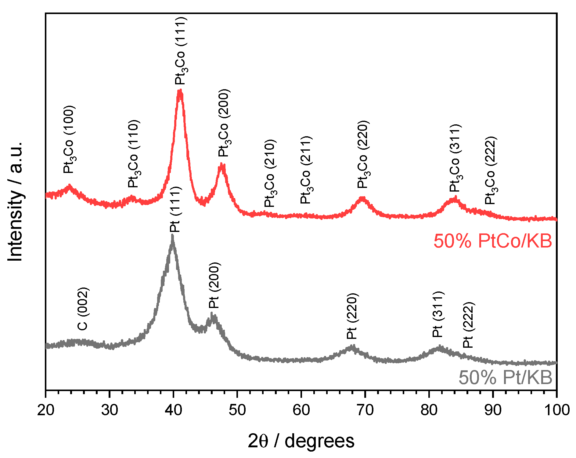
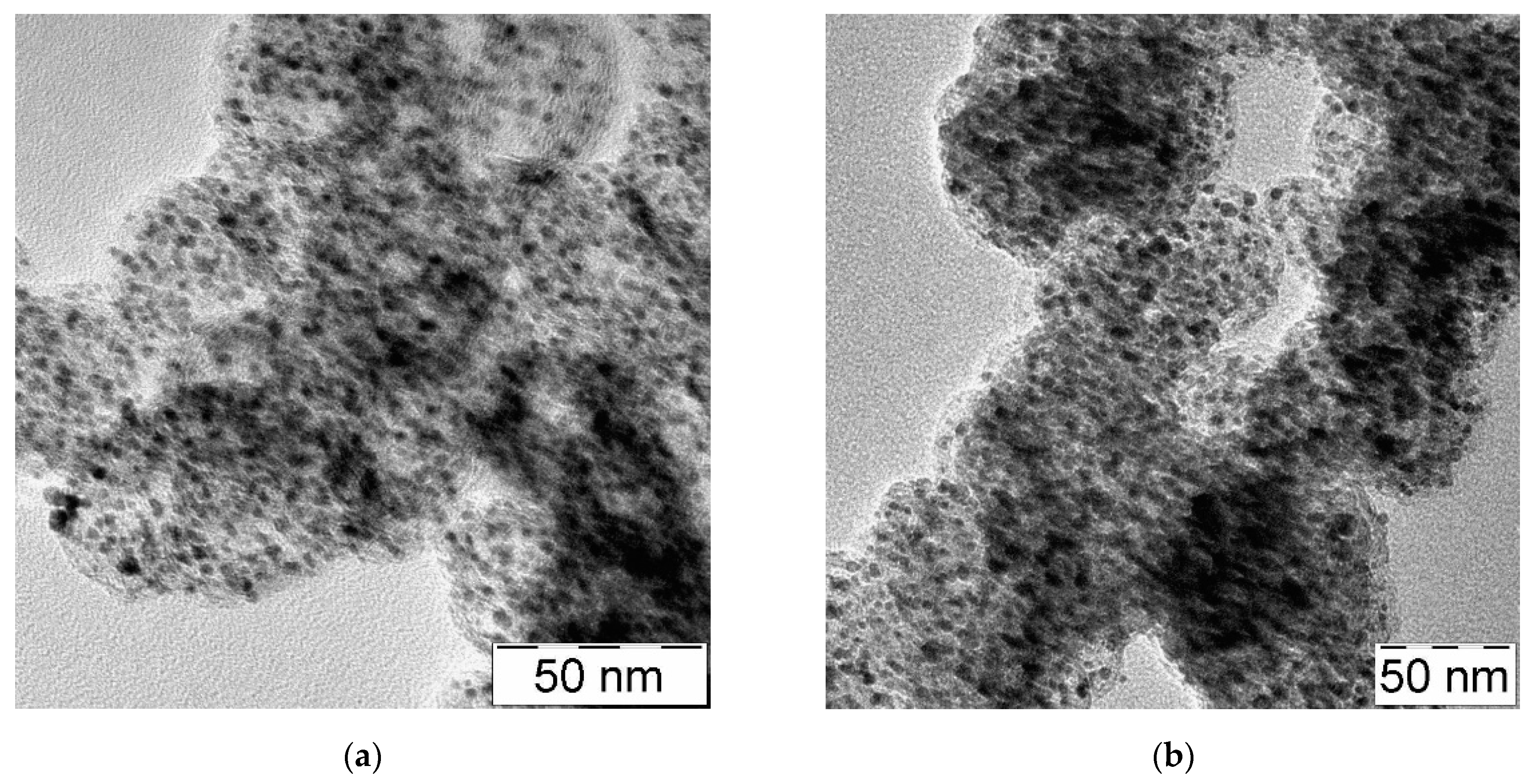
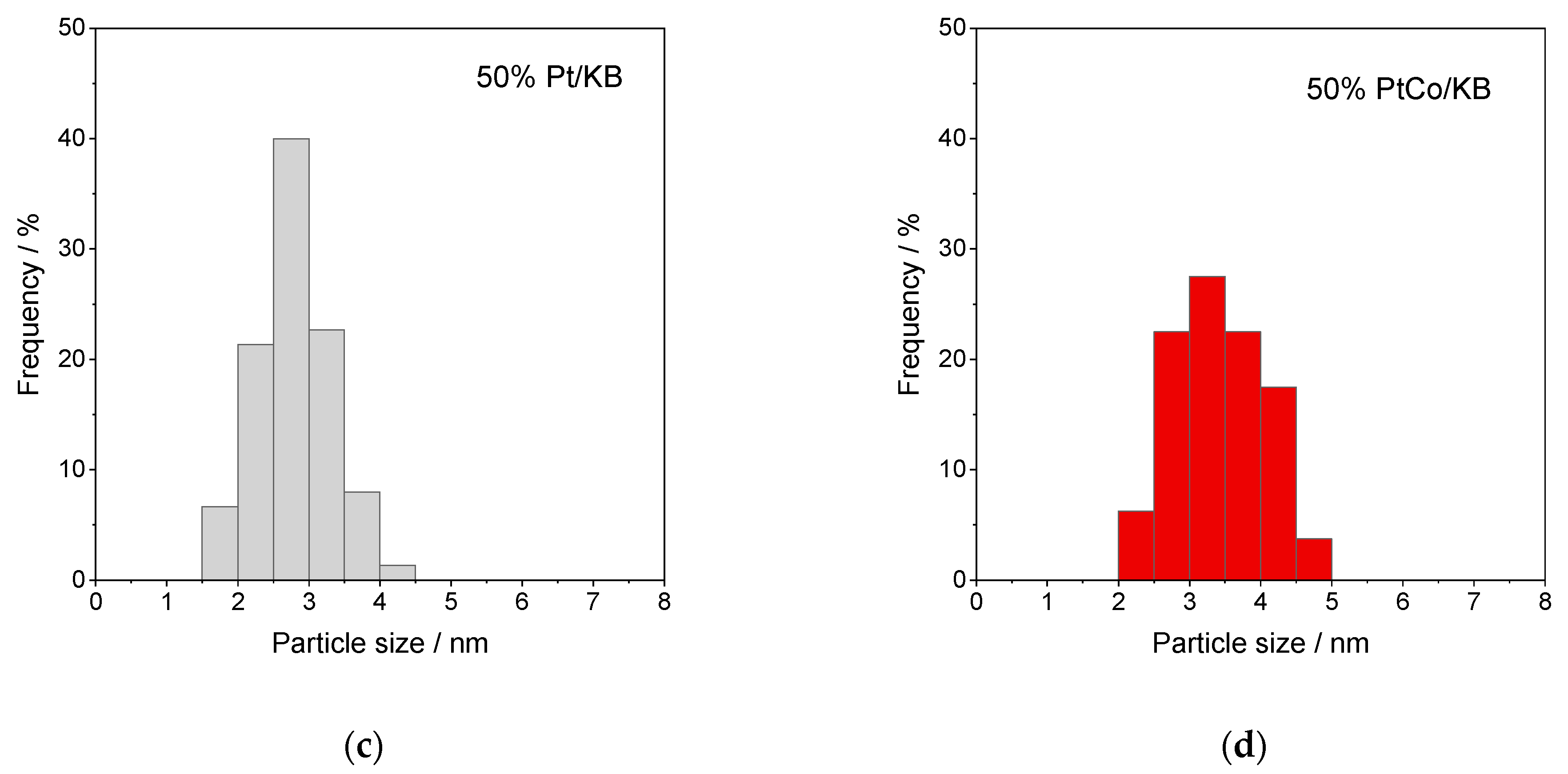
2.2.1. Electrocatalysts Characterization
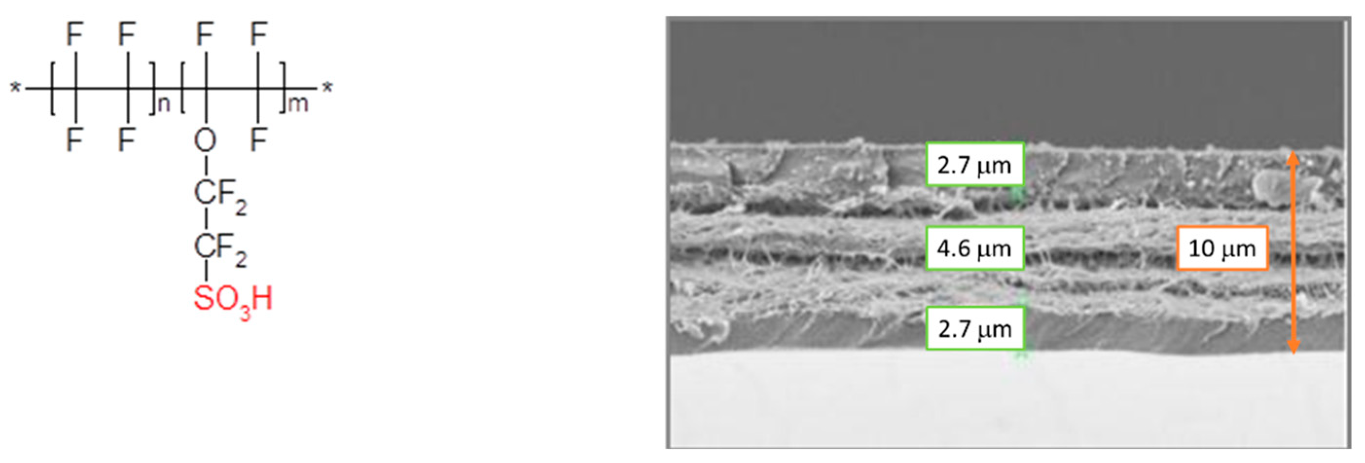
2.2.2. Membrane Characterization
2.2.3. Electrochemical Tests
3. Results and Discussion
4. Conclusions
Author Contributions
Funding
Institutional Review Board Statement
Informed Consent Statement
Data Availability Statement
Conflicts of Interest
References
- Staffell, I.; Scamman, D.; Velazquez Abad, A.; Balcombe, P.; Dodds, P.E.; Ekins, P.; Shah, N.; Ward, K.R. The role of hydrogen and fuel cells in the global energy system. Energy Environ. Sci. 2019, 12, 463–491. [Google Scholar] [CrossRef] [Green Version]
- Whiston, M.M.; Azevedo, I.L.; Litster, S.; Whitefoot, K.S.; Samaras, C.; Whitacre, J.F. Expert assessments of the cost and expected future performance of proton exchange membrane fuel cells for vehicles. Proc. Natl. Acad. Sci. USA 2019, 116, 4899–4904. [Google Scholar] [CrossRef] [PubMed] [Green Version]
- Wang, J. System integration, durability and reliability of fuel cells: Challenges and solutions. Appl. Energy 2017, 189, 460–479. [Google Scholar] [CrossRef]
- Flick, S.; Schwager, M.; McCarthy, E.; Mérida, W. Designed experiments to characterize PEMFC material properties and performance. Appl. Energy 2014, 129, 135–146. [Google Scholar] [CrossRef]
- Wu, H.-W. A review of recent development: Transport and performance modeling of PEM fuel cells. Appl. Energy 2016, 165, 81–106. [Google Scholar] [CrossRef]
- Stassi, A.; Gatto, I.; Baglio, V.; Passalacqua, E.; Aricò, A.S. Investigation of Pd-based electrocatalysts for oxygen reduction in PEMFCs operating under automotive conditions. J. Power Sources 2013, 222, 390–399. [Google Scholar] [CrossRef] [Green Version]
- Marinoiu, A.; Gatto, I.; Raceanu, M.; Varlam, M.; Moise, C.; Pantazi, A.; Jianu, C.; Stefanescu, I.; Enachescu, M. Low cost iodine doped graphene for fuel cell electrodes. Int. J. Hydrogen Energy 2017, 42, 26877–26888. [Google Scholar] [CrossRef]
- Zignani, S.; Baglio, V.; Sebastián, D.; Saccà, A.; Gatto, I.; Aricò, A.S. Towards Highly Performing and Stable PtNi Catalysts in Polymer Electrolyte Fuel Cells for Automotive Application. Materials 2017, 10, 317. [Google Scholar] [CrossRef]
- Shahgaldi, S.; Alaefour, I.; Unsworth, G.; Li, X. Development of a low temperature decal transfer method for the fabrication of proton exchange membrane fuel cells. Int. J. Hydrogen Energy 2017, 42, 11813–11822. [Google Scholar] [CrossRef]
- Tamaki, Y.; Sugiura, K. Influence of the Catalyst Layer Structure Formed by Inkjet Coating Printer on PEFC Performance. Polymers 2021, 13, 899. [Google Scholar] [CrossRef] [PubMed]
- De las Heras, A.; Vivas, F.J.; Segura, F.; Andújar, J.M. From the cell to the stack. A chronological walk through the techniques to manufacture the PEFCs core. Renew. Sustain. Energy Rev. 2018, 96, 29–45. [Google Scholar] [CrossRef]
- Cannio, M.; Righi, S.; Santangelo, P.E.; Romagnoli, M.; Pedicini, R.; Carbone, A.; Gatto, I. Smart catalyst deposition by 3D printing for Polymer Electrolyte Membrane Fuel Cell manufacturing. Renew. Energy 2021, 163, 414–422. [Google Scholar] [CrossRef]
- Fouzai, I.; Gentil, S.; Costa Bassetto, V.; Oliveira Silva, W.; Maher, R.; Girault, H.H. Catalytic layer-membrane electrode assembly methods for optimum triple phase boundaries and fuel cell performances. J. Mater. Chem. A 2021, 9, 11096–11123. [Google Scholar] [CrossRef]
- Poojary, S.; Islam, M.N.; Shrivastava, U.; Roberts, E.; Karan, K. Transport and Electrochemical Interface Properties of Ionomers in Low-Pt Loading Catalyst Layers: Effect of Ionomer Equivalent Weight and Relative Humidity. Molecules 2020, 25, 3387. [Google Scholar] [CrossRef] [PubMed]
- Chen, M.; Zhao, C.; Sun, F.; Fan, J.; Li, H. Reserch progress of catalyst layer and interlayer interface structures in membrane electrode assembly (MEA) for proton exchange membrane fuel cell (PEMFC) system. eTransportation 2020, 5, 100075–100101. [Google Scholar] [CrossRef]
- Gatto, I.; Stassi, A.; Passalacqua, E.; Aricò, A.S. An electro-kinetic study of oxygen reduction in polymer electrolyte fuel cells at intermediate temperatures. Int. J. Hydrogen Energy 2013, 38, 675–681. [Google Scholar] [CrossRef] [Green Version]
- Sebastián, D.; Lemes, G.; Luque-Centeno, J.M.; Martínez-Huerta, M.V.; Pardo, J.I.; Lázaro, M.J. Optimization of the Catalytic Layer for Alkaline Fuel Cells Based on Fumatech Membranes and Ionomer. Catalysts 2020, 10, 1353. [Google Scholar] [CrossRef]
- Gagliardi, G.G.; Ibrahim, A.; Borello, D.; El-Kharouf, A. Composite Polymers Development and Application for Polymer Electrolyte Membrane Technologies—A Review. Molecules 2020, 25, 1712. [Google Scholar] [CrossRef] [Green Version]
- Li, T.; Shen, J.; Chen, G.; Guo, S.; Xie, G. Performance Comparison of Proton Exchange Membrane Fuel Cells with Nafion and Aquivion Perfluorosulfonic Acids with Different Equivalent Weights as the Electrode Binders. ACS Omega 2020, 5, 17628–17636. [Google Scholar] [CrossRef]
- Castriciano, M.; Carbone, A.; Saccà, A.; Donato, M.G.; Micali, N.; Romeo, A.; De Luca, G.; Monsù Scolaro, L. Optical and sensing features of TPPS4 J-aggregates embedded in Nafion_membranes: Influence of casting solvents. J. Mater. Chem. 2010, 20, 2882–2886. [Google Scholar] [CrossRef]
- Carbone, A.; Casciola, M.; Costantino, U.; Ornelas, R.; Fodale, I.; Saccà, A.; Passalacqua, E. Composite nafion membranes based on PWA-Zirconia for PEFCS operating at medium temperature. J. New Mater. Electrochem. Syst. 2004, 7, 1–5. [Google Scholar]
- Kulvelis, Y.V.; Ivanchev, S.S.; Lebedev, V.T.; Primachenko, O.N.; Likhomanov, V.S.; Torok, G. Structure characterization of perfluorosulfonic short side chain polymer membranes. RSC Adv. 2015, 5, 73820–78873. [Google Scholar] [CrossRef]
- Jeon, Y.; Hwang, H.K.; Park, J.; Hwang, H.; Shul, Y.G. Temperature-dependent performance of the polymer electrolyte membrane fuel cell using short-side-chain perfluorosulfonic acid ionomer. Int. J. Hydrogen Energy 2014, 39, 11690–11699. [Google Scholar] [CrossRef]
- Luo, X.; Holdcroft, S.; Mani, A.; Zhang, Y.; Shi, Z. Water, proton, and oxygen transport in high IEC, short side chain PFSA ionomer membranes: Consequences of a frustrated network. Phys. Chem. Chem. Phys. 2011, 13, 18055–18062. [Google Scholar] [CrossRef] [PubMed] [Green Version]
- Radice, S.; Oldani, C.; Merlo, L.; Rocchia, M. Aquivion® PerfluoroSulfonic Acid ionomer membranes: A micro-Raman spectroscopic study of ageing. Polym. Degrad. Stab. 2013, 98, 1138–1143. [Google Scholar] [CrossRef]
- Xiao, P.; Li, J.; Chen, R.; Wang, R.; Pan, M.; Tang, H. Understanding of temperature-dependent performance of short-side-chain perfluorosulfonic acid electrolyte and reinforced composite membrane. Int. J. Hydrogen Energy 2014, 39, 15948–15955. [Google Scholar] [CrossRef]
- Talukdar, K.; Gazdzicki, P.; Friedrich, K.A. Comparative investigation into the performance and durability of long and short side chain ionomers in Polymer Electrolyte Membrane Fuel Cells. J. Power Sources 2019, 439, 227078. [Google Scholar] [CrossRef]
- Shahgaldi, S.; Alaefour, I.; Li, X. The impact of short side chain ionomer on polymer electrolyte membrane fuel cell performance and durability. Appl. Energy 2018, 217, 295–302. [Google Scholar] [CrossRef]
- Gatto, I.; Stassi, A.; Baglio, V.; Carbone, A.; Passalacqua, E.; Aricò, A.S.; Schuster, M.; Bauer, B. Optimization of perfluorosulphonic ionomer amount in gas diffusion electrodes for PEMFC operation under automotive conditions. Electrochim. Acta 2015, 165, 450–455. [Google Scholar] [CrossRef]
- So, S.; Kang, H.; Choi, D.; Oh, K.-H. Tunable aggregation of short-side-chain perfluorinated sulfonic acid ionomers for the catalyst layer in polymer electrolyte membrane fuel cells. Int. J. Hydrogen Energy 2020, 45, 19891–19899. [Google Scholar] [CrossRef]
- Gatto, I.; Carbone, A.; Saccà, A.; Passalacqua, E.; Oldani, C.; Merlo, L.; Sebastián, D.; Aricò, A.S.; Baglio, V. Increasing the stability of membrane-electrode assemblies based on Aquivion® membranes under automotive fuel cell conditions by using proper catalysts and ionomers. J. Electroanal. Chem. 2019, 842, 59–65. [Google Scholar] [CrossRef]
- Garsany, Y.; Atkinson, R.W.; Gould, B.D.; Swider-Lyons, K.E. High power, Low-Pt membrane electrode assemblies for proton exchange membrane fuel cells. J. Power Sources 2018, 408, 38–45. [Google Scholar] [CrossRef]
- Garsany, Y.; Atkinson, R.W., III; Sassin, M.B.; Hjelm, R.M.E.; Gould, B.D.; Swider-Lyons, K.E. Improving PEMFC Performance Using Short-Side-Chain Low-Equivalent-Weight PFSA Ionomer in the Cathode Catalyst Layer. J. Electrochem. Soc. 2018, 165. [Google Scholar] [CrossRef]
- Gatto, I.; Saccà, A.; Baglio, V.; Aricò, A.S.; Oldani, C.; Merlo, L.; Carbone, A. Evaluation of hot pressing parameters on the electrochemical performance of MEAs based on Aquivion ®PFSA membranes. J. Energy Chem. 2019, 35, 168–173. [Google Scholar] [CrossRef] [Green Version]
- Stassi, A.; Gatto, I.; Monforte, G.; Baglio, V.; Passalacqua, E.; Antonucci, V.; Aricò, A.S. The effect of thermal treatment on structure and surface composition of PtCo electro-catalysts for application in PEMFCs operating under automotive conditions. J. Power Sources 2012, 208, 35–45. [Google Scholar] [CrossRef] [Green Version]
- Aricò, A.S.; Stassi, A.; Modica, E.; Ornelas, R.; Gatto, I.; Passalacqua, E.; Antonucci, V. Performance and degradation of high temperature polymer electrolyte fuel cell catalysts. J. Power Sources 2008, 178, 525–536. [Google Scholar] [CrossRef]
- D’Urso, C.; Oldani, C.; Baglio, V.; Merlo, L.; Aricò, A.S. Towards fuel cell membranes with improved lifetime: Aquivion® Perfluorosulfonic Acid membranes containing immobilized radical scavengers. J. Power Sources 2014, 272, 753–758. [Google Scholar] [CrossRef]
- Gatto, I.; Saccà, A.; Carbone, A.; Pedicini, R.; Urbani, F.; Passalacqua, E. CO-tolerant electrodes developed with phosphomolybdic acid for polymer electrolyte fuel cell (PEFCs) application. J. Power Sources 2007, 171, 540–545. [Google Scholar] [CrossRef]
- Gatto, I.; Saccà, A.; Carbone, A.; Pedicini, R.; Passalacqua, E. MEAs for polymer electrolyte fuel cell (PEFC) working at medium temperature. J. Fuel Cell Sci. Technol. 2006, 3, 361–365. [Google Scholar] [CrossRef]
- Santamaria, M.; Pecoraro, C.M.; Di Franco, F.; Di Quarto, F.; Gatto, I.; Saccà, A. Improvement in the performance of low temperature H2-O2 fuel cell with chitosan-phosphotungstic acid composite membranes. Int. J. Hydrogen Energy 2016, 41, 5389–5395. [Google Scholar] [CrossRef]
- Donnadio, A.; Pica, M.; Carbone, A.; Gatto, I.; Posati, T.; Mariangeloni, G.; Casciola, M. Double filler reinforced ionomers: A new approach to the design of composite membranes for fuel cell applications. J. Mater. Chem. A 2015, 3, 23530–23538. [Google Scholar] [CrossRef]
- Lee, J.H.; Doo, G.; Kwon, S.H.; Choi, S.; Kim, H.-T.; Lee, S.G. Dispersion-Solvent Control of Ionomer Aggregation in a Polymer Electrolyte Membrane Fuel Cell. Sci. Rep. 2018, 8, 10739. [Google Scholar] [CrossRef] [PubMed] [Green Version]
- Shukla, S.; Bhattacharjee, S.; Weber, A.Z.; Secanella, M. Experimental and Theoretical Analysis of Ink Dispersion Stability for Polymer Electrolyte Fuel Cell Applications. J. Electrochem. Soc. 2017, 164, F600–F609. [Google Scholar] [CrossRef]
- Sun, L.; Zhang, H.; Ilavsky, J.; Li, Z.-F.; Xie, J. Investigation of Solvent Effects on the Dispersion of Carbon Agglomerates and Nafion Ionomer Particles in Catalyst Inks Using Ultra Small Angle X-Ray Scattering and Cryo-TEM. ECS Trans. 2012, 50, 1461–1466. [Google Scholar] [CrossRef]
- Khandavalli, S.; Iyer, R.; Park, J.H.; Myers, D.J.; Neyerlin, K.C.; Ulsh, M.; Mauger, S.A. Effect of Dispersion Medium Composition and Ionomer Concentration on the Microstructure and Rheology of Fe−N−C Platinum Group Metal-free Catalyst Inks for Polymer Electrolyte Membrane Fuel Cells. Langmuir 2020, 36, 12247–12260. [Google Scholar] [CrossRef]
- Xie, J.; Xu, F.; Wood, D.L., III; More, K.L.; Zawodzinski, T.A.; Smith, W.H. Influence of ionomer content on the structure and performance of PEFC membrane electrode assemblies. Electrochim. Acta 2010, 55, 7404–7412. [Google Scholar] [CrossRef]


| MEA | Catalytic Ink Dispersion Agent | Ionomer Amount, wt.% |
|---|---|---|
| 26-H2O | H2O | 26 |
| 26-EtOH | EtOH | 26 |
| 16-EtOH | EtOH | 16 |
| 36-EtOH | EtOH | 36 |
| Operating Conditions | jm @ 0.9VIRfree, mA mg−1 | ECSA, m2 g−1 | ||
|---|---|---|---|---|
| 26-H2O | 26-EtOH | 26-H2O | 26-EtOH | |
| 80 °C, 50%RH, 1.5 bar | 257 | 304 | 36 | 37 |
| 95 °C, 50%RH, 2 bar | 257 | 357 | 30 | 32 |
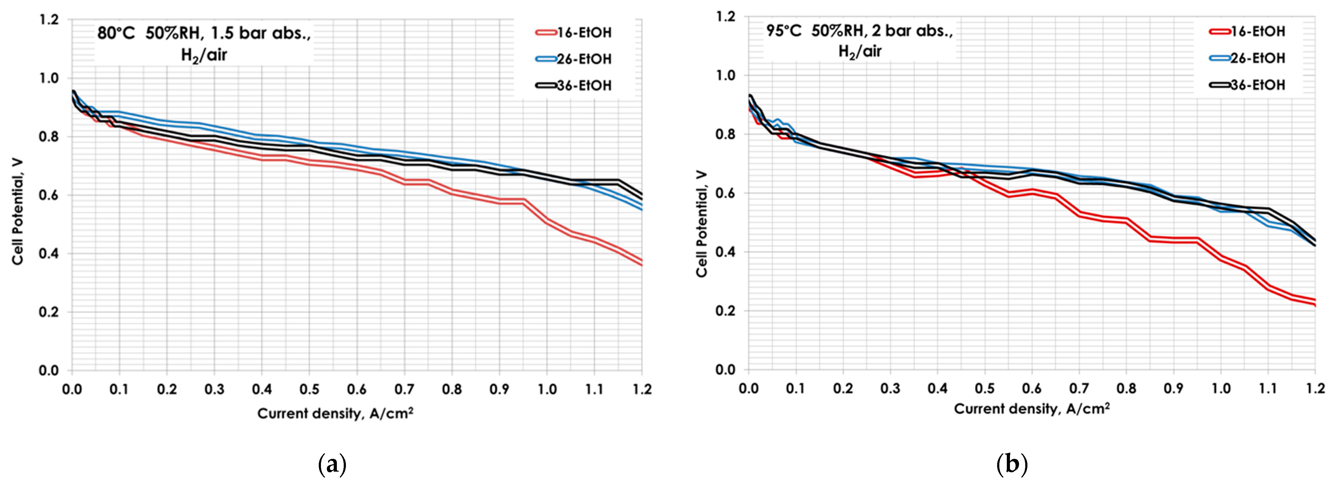
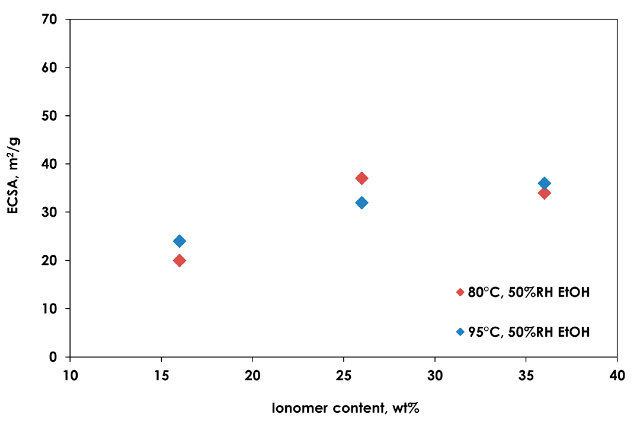
| MEA | 80 °C, 50%RH | 95 °C, 50%RH | ||
|---|---|---|---|---|
| ECSA, m2 g−1 | jm @ 0.9VIRfree, mA mg−1 | ECSA, m2 g−1 | jm @ 0.9VIRfree, mA mg−1 | |
| 16-EtOH | 20 | 207 | 24 | 106 |
| 26-EtOH | 37 | 304 | 32 | 357 |
| 36-EtOH | 34 | 155 | 36 | 205 |
Publisher’s Note: MDPI stays neutral with regard to jurisdictional claims in published maps and institutional affiliations. |
© 2021 by the authors. Licensee MDPI, Basel, Switzerland. This article is an open access article distributed under the terms and conditions of the Creative Commons Attribution (CC BY) license (https://creativecommons.org/licenses/by/4.0/).
Share and Cite
Gatto, I.; Saccà, A.; Sebastián, D.; Baglio, V.; Aricò, A.S.; Oldani, C.; Merlo, L.; Carbone, A. Influence of Ionomer Content in the Catalytic Layer of MEAs Based on Aquivion® Ionomer. Polymers 2021, 13, 3832. https://doi.org/10.3390/polym13213832
Gatto I, Saccà A, Sebastián D, Baglio V, Aricò AS, Oldani C, Merlo L, Carbone A. Influence of Ionomer Content in the Catalytic Layer of MEAs Based on Aquivion® Ionomer. Polymers. 2021; 13(21):3832. https://doi.org/10.3390/polym13213832
Chicago/Turabian StyleGatto, Irene, Ada Saccà, David Sebastián, Vincenzo Baglio, Antonino Salvatore Aricò, Claudio Oldani, Luca Merlo, and Alessandra Carbone. 2021. "Influence of Ionomer Content in the Catalytic Layer of MEAs Based on Aquivion® Ionomer" Polymers 13, no. 21: 3832. https://doi.org/10.3390/polym13213832