3.2. First Stage. Effect of Silane Treatment
The effect of untreated and treated CSF filler in a Bio-HDPE matrix was investigated by evaluating the tensile, ductile, hardness and impact properties.
Table 2 gathers the properties obtained. Firstly, the tensile strength of Bio-HDPE was around 373 MPa and decreased with the addition of CSF filler (untreated and treated). This behavior was expected due to the addition of filler, which causes a decrease in interfacial adhesion because the filler tends to form agglomerates increasing the stress concentrations and, as a result, lower tensile strength [
57]. Regarding the effect of silane treatment, which was evaluated with 20 wt.% of CSF, it was observed that the 20UT sample presented 10.8% less tensile strength than the 20T sample. This reduction of tensile strength was attributed to weak interfacial adhesion between UTCSF and the Bio-HDPE matrix. It is known that organosilanes consist of two different reactive molecules: the silanol groups react with the hydroxyl groups presents in CSF, whereas the functional groups of the APS react with the polymeric matrix by covalent bonding [
58]. In addition, it has been reported that treatment of lignocellulosic flour with APS coupling agent improved the interfacial adhesion with Bio-HDPE [
59]. This better adhesion/interaction allowed a uniform stress distribution from polymer to filler, achieving a higher tensile strength than untreated samples. Similar findings have been reported by Ihamounchen et al. [
60], who evaluated the addition of olive husk flour (OHF) treated with vinyltriacetoxysilane (OHFTA) in HDPE. In this study an increment from 13% to 3% in tensile strength with 10 and 30 wt.% of OHF was reached compared to untreated samples, respectively. Regarding tensile modulus, the untreated sample (20UT) presented a value of 374 MPa whereas a treated sample (20T) showed an increment of 5.9% compared to the 20UT sample. Finally, elongation at break was dramatically decreased after filler addition. Bio-HDPE presented a high elongation at break of 520%, showing high ductility properties as has been reported previously [
44]. When 20 wt.% of untreated CSF was added, this parameter dropped drastically to a value below 36%, which is 93% lower than Bio-HDPE. On the other hand, if this amount of filler is treated with APS the decrease is pronounced, but lower than 90% with respect to the Bio-HDPE. Therefore, it has been observed that CSF treated with APS presented higher elongation at break than a 20UT sample with an improvement of 41%. Comparing these results with the use of a polypropylene-graft-maleic copolymer (PP-g-ma) as compatibilizer between peanut shell and polyethylene, lower enhancement in elongation at break were obtained [
61]. In this study the introduction of PP-g-ma does not improve this feature compared to sample without compatibilizer, which highlights the efficiency of the APS.
With regard to flexural properties, no significant changes were recorded in flexural strength with the addition of CSF filler. In addition, the silane treatment with APS does not show significant differences. Regarding flexural modulus of the 20UT sample, a decrease from 804 MPa for neat Bio-HDPE to 784 MPa was observed. Regarding samples with CSF treated with APS, an evident improvement was observed compared to 20UT samples. The same behavior was obtained by Boronat et al. who evaluated Bio-HDPE with eggshells with silane treatment [
44]. In another study, a maleic anhydride grafted polystyrene (Xibond
TM 160) was employed as a compatibilizer in a cellulose/ABS composite [
62]. The addition of this copolymer led to a 1.75% improvement of the flexural modulus compared to a sample without compatibilizer. This value was lower than that obtained with APS in the current study that achieved an improvement of 7% regarding the untreated sample. In general, these tendencies were in concordance with values previously recorded for tensile properties, where samples treated with silane present higher mechanical resistances properties than untreated samples.
Regarding Shore D hardness, it increased with addition of CSF due to the intrinsic hardness of lignocellulosic filler which leads to an increase of the hardness of the composite [
63]. In relation to untreated and treated CSF, there was a slight improvement with the 20T sample. This fact was attributed to the strong adhesion between CSF and the matrix produced after silane treatment [
64]. On the other hand, the impact energy, that is related to the deformation capacity, is highly sensitive of stress concentrators [
65]. The addition of 20 wt.% of CSF led to a decrease in impact absorbed energy compared to Bio-HDPE. In this instance, it has not been possible to transfer the impact load from the matrix to the filler thus reducing the impact absorbed energy with CSF addition. Comparing 20UT and 20T samples, an improvement of 13% in impact energy was observed when filler was treated with APS. This behavior was due to the silane coupling agent acting as a bridge between CSF and Bio-HDPE matrix through chemical bonding, which reduces any crack propagation by means of a good dispersal of the impact energy [
66].
In
Figure 1, the morphology of fractured surfaces from Charpy tests are shown with the aim of evaluating the effect of silane treatment on the interfacial adhesion between CSF and the matrix. As can be observed in
Figure 1a, Bio-HDPE showed the typical rough and irregular surface of a ductile polymer as also reported by Rojas et al. [
67]. As it has been described previously, the treatment of CSF with APS has a positive effect on mechanical resistance properties such as strength, modulus, or hardness whereas a decrease of mechanical ductile properties such as elongation at break was detected. The effect of silane treatment can be compared in
Figure 1b,c at 1000× where CSF particles are highlighted with a yellow arrow. In the case of an untreated sample (20UT) a clear gap can be distinguished in the perimeter between the polymer matrix and a CSF particle highlighted by the red arrow in
Figure 1b. This gap indicated the lack of particle-matrix interaction that does not allow it to transfer stress, and this justifies the decrease in elongation at break and impact energy [
60]. Moreover, Toro et al. indicated that when cracks are produced by an impact, these are propagated towards the poor interfacial regions, leading a break in the composites with low stresses [
68]. Regarding the treated sample (20T), the gap between the CSF particle and polymer matrix has been broadly reduced when CSF was treated with silane coupling, as has been highlighted with a red arrow in
Figure 1c. This indicated that a better interfacial adhesion was achieved between the two phases. This confirms the enhancement of mechanical properties and elongation at break compared to untreated samples. Bijaisoradat et al. also observed that voids between filler and matrix was reduced when evaluating wood flour treated by trimethoxy (propyl)silane (MPS) in HDPE [
69].
The effect of untreated and treated CSF filler in the Bio-HDPE matrix was studied by DMTA in torsion mode.
Figure 2 shows the storage modulus (G’) of samples with respect to the temperature. Firstly, Bio-HDPE presented the lowest G’ as was expected. As has been mentioned previously, the tensile and flexural modulus presented a clear increase with 20UT and 20T samples compared to Bio-HDPE. In this case, the same trend was observed because of the restriction of polymer chain mobility through addition of CSF filler, hence increasing the stiffness of the composite [
70]. Regarding the effect of silane treatment, it was observed that 20T sample presented a higher G’ than the 20UT sample over all temperatures, which means an increase of 2.5% at room temperature. This fact csn be explained by the better compatibility between CSF and matrix as was observed in FESEM. These values were in concordance with the mechanical properties discussed above.
The influence of silane coupling treatment on the thermal properties has been investigated by DSC.
Table 3 gathers the main thermal properties. Bio-HDPE showed a melt temperature of 131 °C, a value in concordance with the result of Quiles-Carillo et al. [
71]. In addition, it was observed that the melting temperatured of 20UT and 20T samples are not affected significantly compared to Bio-HDPE. It has been widely reported that silane coupling agent does not directly affect the melting temperature [
59,
72,
73]. With respect to the melting enthalpy, it was decreased with addition of CSF filler due to both the effect of filler content and the matrix reduction (Bio-HDPE). Finally, the effect of silane treatment on crystallinity is shown in
Table 3. The addition of treated CSF (20T) allowed an increase in the crystallinity compared to untreated CSF (20UT). This behavior was due to a better interaction between phases that may improve the nucleation activity with the presence of CSF treated with APS [
74]. Therefore, the lack of interaction of untreated CSF led to difficult the arrangement of molecular chains, decreasing the crystallinity.
Thermogravimetric analysis (TGA) was performed to assesses the thermal stability of neat Bio-HDPE, CSF particles and the effect of silane treatment with 20 wt.% of CSF in the Bio-HDPE matrix.
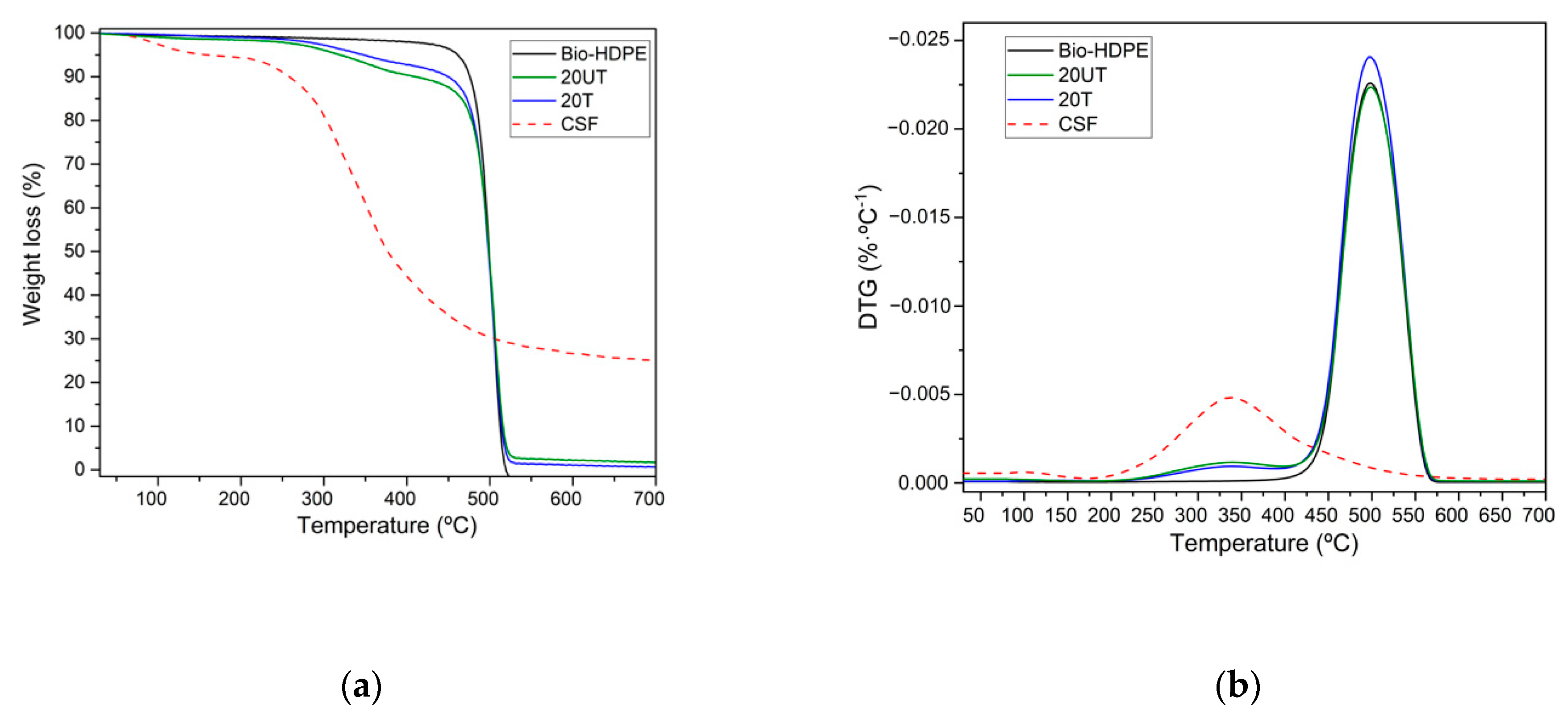
Figure 3 shows the TGA curves and the first derivative (DTG). As observed in
Figure 3a, a weight loss of Bio-HDPE was associated with a single-phase degradation. At a temperature of 100 °C no weight loss due to evaporation of residual moisture was measured in the samples, due to their characteristic hydrophobic nature. Bio-HDPE degradation proceeded in one step that began about 350 °C up to 520 °C where a weight loss of 99% was measured. This one step degradation was produced by random scission of the C-C and C-H bonds present in Bio-PE [
75]. A similar temperature profile trend was observed by Montanes et al. [
76]. Regarding the weight loss of CSF, it was associated with the four stages characteristic of lignocellulosic particles. The initial weight loss recorded was 7.5% in the 30–220 °C range, which was attributed to evaporation of residual moisture contained in the particles [
77]. The second step was produced between 220 °C and 350 °C approximately, with a weight loss of 40%. This loss was due to the decomposition of low molecular weight products such as hemicellulose. The third stage corresponds to around 60% of weight loss in the 350–410 °C range due to decomposition of cellulose. The last step, characterized by a weight loss of 75%, was related to lignin degradation at temperatures above than 410 °C [
78]. Two different stages were identified in the evaluation of the effect of CSF particles in the Bio-HDPE matrix. The first stage, at temperatures in the 280–430 °C range, was related to the lignocellulosic filler decomposition mentioned above. It was observed that addition of CSF filler led to decrease in the thermal stability. The second stage was measured above 430 °C and is characterized by Bio-HDPE degradation. Regarding the effect of silane treatment, a treated sample (20T) displayed higher thermal stability than an untreated (20UT) one. This could be attributed to the improvement of matrix filler interactions after silane coupling agent addition, which led to enhanced thermal stability [
64]. In
Figure 3b two maximum degradation stages can be observed for all samples. The first stage was related to CSF degradation at temperatures around 350 °C, thus not displaying any evidence of weight loss for Bio-HDPE as expected. In addition, the maximum temperature for the first stage was not shifted depending on the CSF filler surface treatment. Finally, the second stage was related to Bio-HDPE degradation. In this case, the second maximum degradation temperature was 498 °C and no signs of changes were recorded, maintaining the thermal stability. However, the results reported by Fonsenca et al. showed a shift to lower temperatures of the peak maximum peak degradation of ABS with a cellulose fiber composite using a maleic anhydride grafted polystyrene as compatibilizer, reducing the thermal stability [
62].
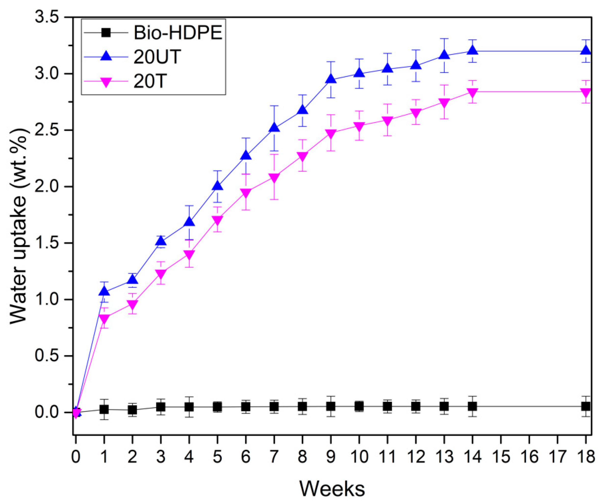
With the objective of measuring the effect of silane treatment on the water uptake of the developed composites, the absorption of water was evaluated by means of immersion in distiller water for 18 weeks. In
Figure 4 it can be observed that Bio-HDPE presented less than 0.05 wt.% water absorption. It is known that polyethylene is a hydrophobic polymer as has been reported by Perthue et al. [
79], who reported the same absorption value. In addition, CSF presents the hydrophilic nature characteristic of lignocellulosic fillers. Thus, the addition of filler leads to an increase in the water absorption of composites. The free hydroxyl groups present in CSF may react with hydrogen bonds of water allowing water to diffuse inside the composite [
80]. The effect of silane treatment on CSF was clearly observed by comparing 20UT and 20T samples. A decrease of 17% in water absorption was recorded for the 20T sample compared to the 20UT sample. After silane treatment there is less availability of hydroxyl groups in CSF filler to create hydrogen bonding with water, thus rendering lignocellulosic filler more hydrophobic [
81]. In addition, we should remark that from 14 to 18 days, a constant water uptake was measured for all samples studied, indicating no further absorption.
Degradation of Bio-HDPE with untreated and treated CSF filler is shown in
Figure 5. Bio-HDPE presents several features such as high molecular weight, hydrophobicity and the lack of functional groups that are recognizable by microbial systems, which make it essentially a non-biodegradable polymer [
82,
83]. After 8 days, Bio-HDPE does not show any weight loss whereas 20UT and 20T samples presented a slight weight loss. On the 21st day a weight loss higher than 2.5% was recorded for both untreated and treated samples with 20 wt.% of CSF. According to Peng et al. [
77], lignocellulosic filler is biodegradable at a reasonable rate and can be fully degraded after longer periods ranging from 1 to 3 months using the soil burial method. The recorded degradation was related to the lignocellulosic filler which biodegrades due to the deterioration of lignin, hemicellulose and cellulose caused by microorganisms [
84]. It should be mentioned that the Bio-HDPE matrix was not affected after 90 days, displaying a weight loss of less than 0.05% as plotted in
Figure 5. Regarding to effect of silane treatment, the 20UT sample achieved a higher disintegration rate than 20T sample, reaching 8.5% and 4.21% after 18 weeks, respectively. It is known that hydrophilic nature of lignocellulosic filler facilitates the transfer of water and microorganisms or enzymes into the composite, thus speeding up the disintegration process [
74]. The improvement of interfacial adhesion due to silane treatment hinders the introduction of water and microorganism action in composites, reducing the degradation [
74]. This behavior was in concordance with the water uptake results obtained, where the 20UT sample present a higher water absorption than a 20T sample, thus leading to a sped-up disintegration rate.
After studying the effect of silane coupling agent in Bio-HDPE with CSF filler, it has been determined that in general, silane treatment improves the mechanical resistance properties and main aspects such as the water uptake capacity and minimizes the disintegration rate under composting conditions. By FESEM it has been observed how the gap between filler and matrix was reduced with silane treatment, which justifies the mechanical property improvement. Moreover, silane agent provided a nucleation effect, a decrease of the water absorption due to decrease of available hydroxyl groups and thus slightly decreased the rate of degradation.
3.3. Second Stage. Evaluation of CSF Filler Percentage
Once the effect of APS as a coupling agent had been studied, the aim was to study how CSF filler content modified with APS affects the mechanical, thermal, and morphological properties of the Bio-HDPE. The same order of characterization as in the first stage was followed.
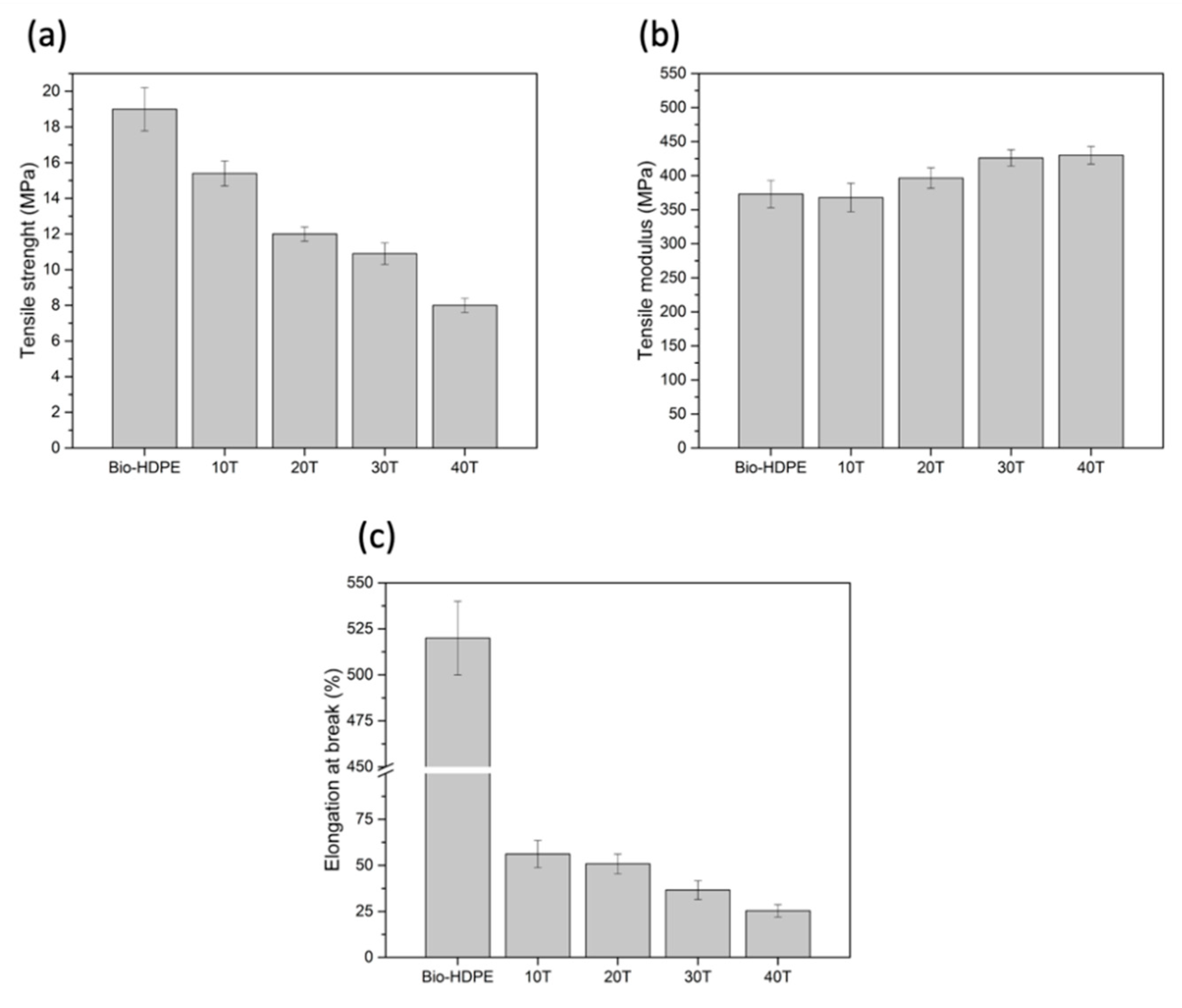
Tensile properties of Bio-HDPE with different content of CSF are shown in
Figure 6. As can be seen in
Figure 6a, the tensile strength decreased with increasing filler content. The lowest tensile strength recorded was 8 MPa for the 40T sample, which was a decrease of 58% compared with Bio-HDPE. This behaviour was directly related to the interfacial adhesion between CSF and matrix, which is crucial in reinforced composites to allow the tranfer of a small stress to filler particles during deformation [
45]. Therefore, a higher content of filler implies less interaction between the matrix and particles, and thus more stress concentration appeared that induces the strength to decrease [
85]. Regarding the tensile modulus,
Figure 6b showed an increase with addition of CSF content in the matrix. In this case, the highest elastic modulus was obtained for the 40T sample, which represents an increment of 22% compared to neat Bio-HDPE. No significant difference was observed when comparing the 30T and 40T samples, indicating that a higher addition of CSF filler does not necessarily lead to an increase of elastic modulus. In addition, the increment of elastic modulus could confirm that CSF presents the rigid nature typical of lignocellulosic fillers. This trend indicated an increment of stiffness of composite due to restriction of chain mobility caused by the presence of filler particles [
63]. Finally, as was shown in
Figure 6c, the elongation at break of Bio-HDPE decreased dramatically as the filler content increased, going from 520% for Bio-HDPE to 23.5% for the 40T sample, respectively. This behaviour was attributed to the presence of stress caused by the dispersed rigid filler that increased the higher the filler content is [
61]. This trend has also been found by Chun et al. when studying the effect of coconut shell powder (CSP) with 3-aminopropyl-triethoxysilane (3-APE) silane coupling in a PLA matrix [
72]. In this study, despite the enhancement of interfacial adhesion obtained using aminosilane, a reduction of elongation at break occurred.
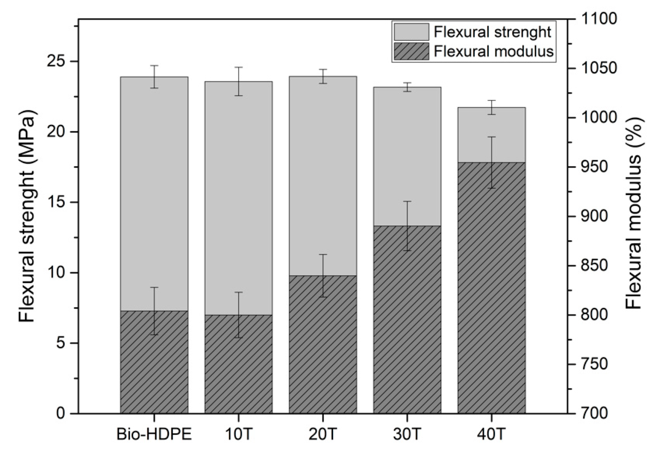
A similar behaviour was observed in flexural properties (
Figure 7). As shown in
Figure 7, the flexural strength decreased slightly with the addition of CSF to the matrix. Although the changes recorded are not very significant, a clear tendency was observed. The lowest flexural strength measured was 21.7 MPa for 40 wt.% of CSF, representing a decrease of 9.6% compared to Bio-HDPE with 24 MPa. With respect to flexural modulus, it was highly improved with the addition of filler. Addition up to 20 wt.% of CSF showed an increase of 4% compared to unfilled material, achieving an average value of 845 MPa approximately. However, a very similar addition of 30 wt.% showed a significant increment of 10% and 18% in flexural modulus regarding Bio-HDPE for 30 and 40 wt.%, respectively. As mentioned above, for the lowest filler content (10 and 20 wt.%) a slight increase was measured. This fact is due to better filler dispersion in the matrix as well as the substantial distance between filler particles. Nevertheless, the flexural modulus for high filler content was increased noticeably because the distance was decreased by the addition of filler and the effect of each CSF particle was superposed providing an evident enhancement [
86]. In general, these tendencies were in concordance with the previously recorded tensile properties, where the tensile modulus increased, and tensile strength decreased as filler content was added.
Shore D hardness and impact absorbed energy results are gathered in
Table 4. Firstly, hardness is related to the mechanical resistance properties and a gradual increase was observed as the addition of CSF filler increased. In this case, the 40T sample showed a Shore D hardness of 63, which represents an increment of 11% compared to Bio-HDPE. This fact was expected because lignocellulosic filler presents higher hardness than the soft polymer matrix, which leads to an increase in the hardness of composites [
87]. It should be noted that the evolution of hardness was in concordance with the tensile and flexural modulus results. In contrast, the toughness of composites, which is the ability to absorb energy during deformation, was decreased as the addition of CSF to the matrix increased. The lowest impact absorbed energy recorded was 1.6 kJ·m
−2 for 40 wt.% of CSF, which represents a decrease of 38% compared to Bio-HDPE (2.6 kJ·m
−2). As expected, filler addition generated higher stress concentration as well as restricted the deformation, which leads to decreased absorbed energy [
88]. Furthermore, this tendency was in concordance with the evolution of elongation at break and the typical mechanical ductile properties mentioned above.
In
Figure 8 the fractured surface morphology after impact tests of Bio-HDPE with different percentages of treated CSF with APS are shown in order to evaluate filler-matrix interactions. In
Figure 8a the typical irregular and rough surface of a ductile polymer like Bio-HDPE is shown, where an an absence of CSF particles is observed. In general, after addition of CSF particles, highlighted in yellow arrows (
Figure 8b–e), good bonding by Bio-HDPE matrix was observed. As mentioned previously, CSF particles treated with APS showed improved compatibility with matrix reducing the gap between phases. Nevertheless, as higher CSF particle addition levels, more presence of small gaps in the perimeter between CSF and the surrounding Bio-HDPE matrix was observed as marked by orange arrows. It is known that a higher presence of particles in the matrix, despite using compatibilizers, generates more voids between particles and the matrix [
89]. This fact causes an increment of stress concentrators and therefore a loss of mechanical properties as was shown previously [
85]. Similar findings were obtained by Garcia-Garcia et al. who evaluated different percentages of peanut shell powder (PSN) in a Bio-HDPE matrix, where despite the use of compatibilizers, some voids between particles and the matrix causing a decrease in elongation at break and tensile strength are still observed [
61].
DMTA in torsion mode, plotted in
Figure 9, represents the evolution of storage modulus (G’) with respect to temperature for Bio-HDPE and different composites developed with Bio-HDPE and CSF. Storage modulus, which is related to the stiffness of a material, decreased as the temperature increased for all analyzed samples. However, the addition of filler increased the storage modulus values regarding neat Bio-HDPE, with higher values as the CSF content increases. This was more clearly observed at low temperatures (−100 to −80 °C). With respect to room temperature, it was observed that the 40T sample presents a G’ of 105 MPa, which represents an increment of 20% compared to neat Bio-HDPE. This fact confirmed the reinforcing effect that CSF filler provides, which acts as an interlock point in Bio-HDPE matrix that leads to restricted chain mobility, thus increasing the stiffening behaviour of composites [
63]. This trend was also measured previously in tensile and flexural modulus. In addition, a similar behavior has been reported by Barczewski et al. [
20] who evaluated different linseed cake (LC) percentages in HDPE composites. In this study, an increase of G’ with addition of LC was also observed, being more noticeable at low temperatures.
Thermal analysis was performed in order to assess the main thermal transitions and thermal stability for Bio-HDPE and different composites developed with Bio-HDPE and CSF. Thermal parameters obtained by DSC are gathered in
Table 5. It was observed that the addition of CSF to the Bio-HDPE matrix barely affects the melting temperature. Regarding crystallinity, which is directly related to melting enthalpy (
), it was increased with the presence of a low amount of filler (10 and 20 wt.%). This increment in the crystallinity was due to the nucleating effect provided by the CSF filler [
90]. However, a CSF content higher than 20 wt.% led to a decrease of the crystallinity with the lowest value being 49.1% for 40 wt.% of CSF. In general, the crystallinity of composites reinforced with particles depends on two factors: the first is the nucleation effect of fillers and the second is the hindering effect produced by fillers that difficult the movement of molecular chains. However, although filler presented a nucleation effect, high amounts of filler such as 30 and 40 wt.% lead to difficulties in the arrangement of molecular chains, thus decreasing the crystallinity [
91]. This tendency was also reported by Xiong et al. who evaluated HDPE with wood flour with different coupling agents [
59].
In
Figure 10 both TGA curves and their first derivative (DTG) of different composites developed with Bio-HDPE and CSF are plotted. Bio-HDPE presented a temperature for a weight loss of 5 wt.% (T
5%) of around 460.3 °C. The addition of CSF particles in the Bio-HDPE matrix led to a decrease of T
5% as CSF filler was added. As shown in
Figure 10a, T
5% was reduced from 460.3 °C (Bio-HDPE) to 262.3 °C for the 40T sample, which means a decrease of 43%; hence, reduced thermal stability compared to neat Bio-HDPE. This decrease of T
5% is due to the decomposition of the lignocellulosic filler produced in the 220–410 °C range, as exposed previously. In addition, a higher temperature of 410 °C was related to Bio-HDPE degradation, not showing significant changes. Finally, the residual weight recorded from 520 °C to 700 °C, was higher as CSF filler was added, probably due to the presence of more ash content [
92]. In
Figure 10b the first derivative is shown, where two maximum degradation stages in composite reinforced with CSF are clearly observed. The first stage (T
max1) was related to CSF filler degradation which occurred at about 338 °C, and the second stage (T
max2) with Bio-HDPE degradation at 498 °C. As can be observed, the addition of CSF to the matrix does not affect the T
max1 and T
max2. Similar findings have been reported by Yong et al. [
93] for wood plastic composites using polyethylene and wood fiber with different formulations.
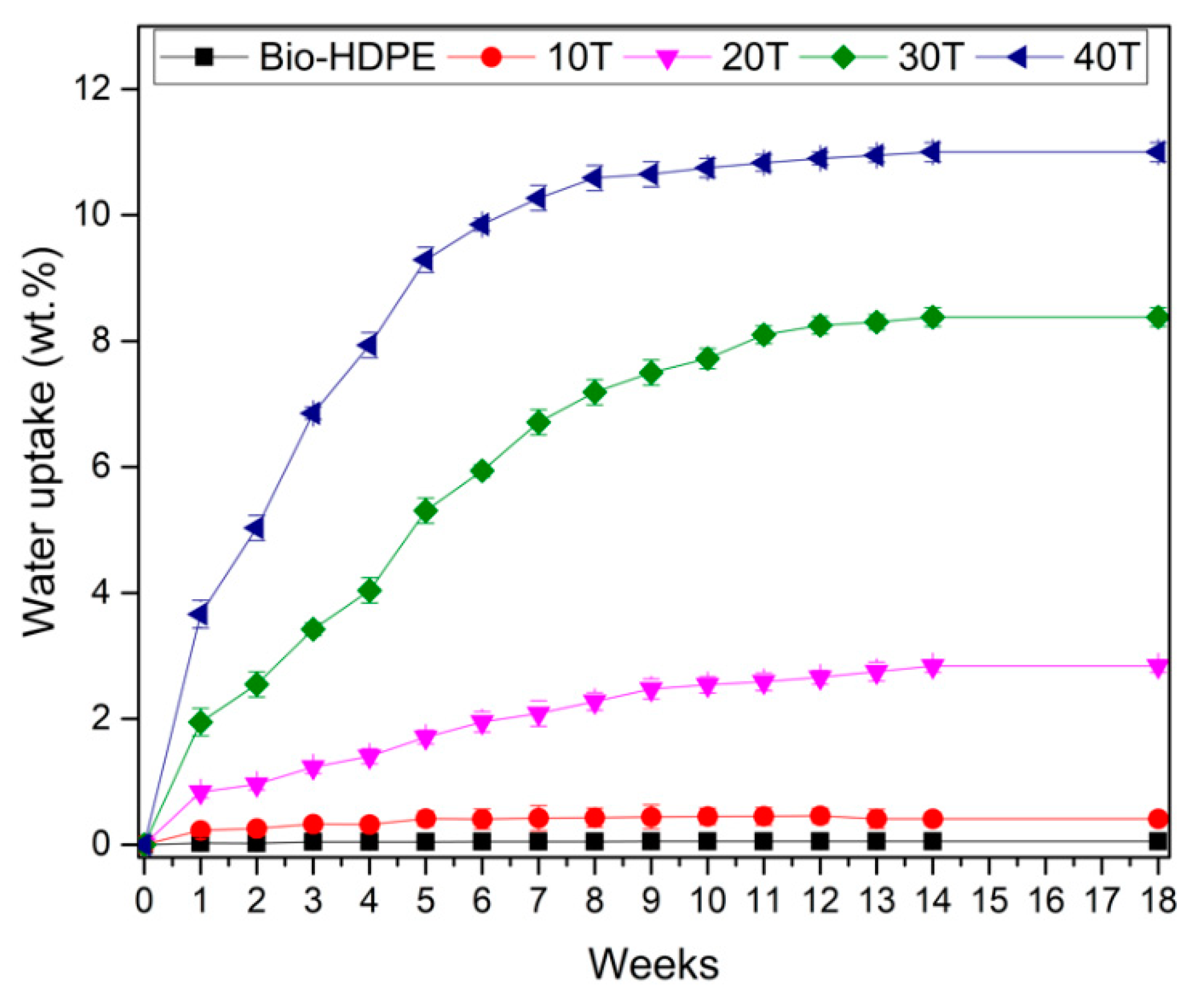
Water absorption of Bio-HDPE with different percentages of CSF filler have been measured. The results obtained after 18 weeks are shown in
Figure 11. This phenomenon depends on the capabilities of matrix and filler to absorb water. Firstly, Bio-HDPE presented less than 0.05% of water absorption which confirms its hydrophobic nature. The addition of CSF filler provided an increment of water absorption due to the hydrophilic nature of CSF, as was described previously. In agreement with the literature, initially a higher water absorption was observed that gradually slows down until saturation was achieved, being in this case at 18 weeks [
94]. The addition up to 20 wt.% presented a slight increase in water absorption reaching almost 3%. However, a notable increase was observed for 30 and 40 wt.% of CSF, where values of 8.25% and 11% were obtained, respectively. This increment of water absorption could be attributed to the presence of mucilage in CSF, which is a polysaccharide gum that represents about 6% of the weight and provides higher water-holding capacity [
80]. Chen et al. [
95] studied the water uptake of rice husk (RH) in a HDPE matrix, reaching values of about 7% with 40 wt.%. Furthermore, Liu et al. [
96] has also reported a water absorption of less than 11% with 50 wt.% of wood flour in a PP matrix, observing a lower value compared to a 40T sample. Nevertheless, general values of water absorption in WPCs are around 14–16% [
95,
97,
98]. Therefore, although Bio-HDPE with CSF particles presented higher values than some WPCs, probably due to the presence of mucilage, it remained below that of general WPCs.
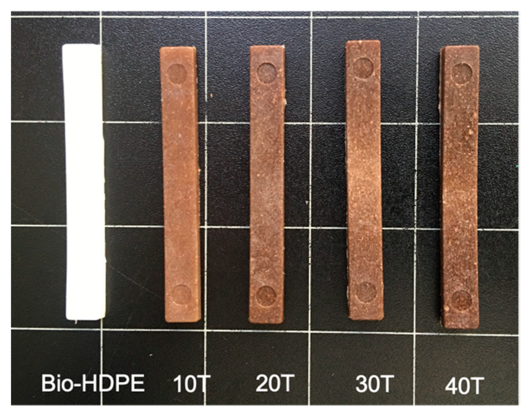
The appearence of materials with fillers are crucial to imitate wood as closely as possible. Parameters such as colour or luminance are important in this approach. Colour coordinates of different Bio-HDPE/CSF composites are gathered in
Table 6 by the values of L*(luminance), a* (green to red), b* (blue to yellow) and colour change (ΔE
ab*). Moreover, the visual appearance of samples is shown in
Figure 12. Firstly, the sample with highest luminance was Bio-HDPE, caused by its white colour with a value of 71.3. With the addition of lignocellulosic filler, luminance was reduced in the range of 36.6–42.5 compared to neat Bio-HDPE. Regarding a*, Bio-HDPE presented a negative value of −2.6 which was close to 0 that indicates the closeness to white colour. On the contrary, the rest of samples had positive values due to the characteristic brown colour of chia seed flour [
99]. Higher values of a* coordinate have been reported by Jorda-Reolid et al. [
100] who employed Bio-HDPE with argan shell wastes. In this study a higher a* value above 5 was reported, thus a reddish brown colour was obtained [
100]. Referring to colour coordinate b*, it is an indicative of blue to yellow colours. Bio-HDPE presented a negative value of −2.68 which is in concordance with Rojas et al. [
67]. The rest of samples had values between 5.72 and 8 which indicate a tonality approaching yellow. Regarding the colour change variation, it should be noted that a difference of colour change between Bio-HDPE and CSF composites exists. This change was more noticeable as the addition of CSF fillers was increased.
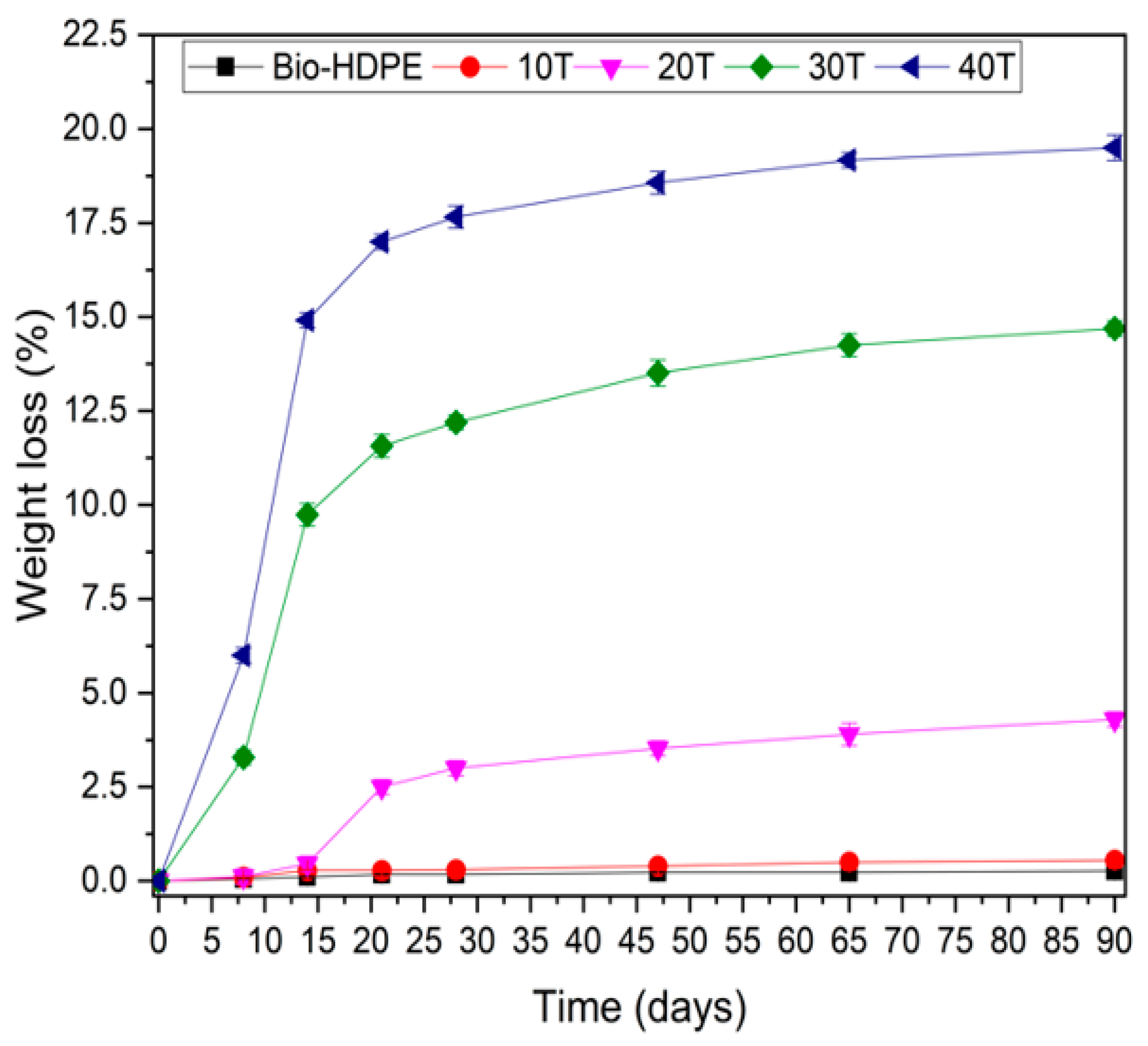
The disintegration process of Bio-HDPE with different percentages of CSF is plotted in
Figure 13. As it was mentioned previously, Bio-HDPE is a non-biodegradable polymer and no sign of weight loss was recorded after 90 days. The absence of hydrolyzable zones in its structure that can be attacked by microorganisms means that after 90 days of testing, the disintegrated mass is almost nil. However, the addition of CSF filler, as expected, increased the disintegration rate up to 6% weight loss after only 8 days for a 40T sample. It is known that lignocellulosic filler, which is composed of lignin, hemicellulose and cellulose, is biodegraded by microorganisms [
84]. Disintegration weight loss was greatly increased up to 21 days with addition of filler, where 16.5% of weight loss was measured in the 40T sample. However, from 21 to 90 days only a slight increase from 16.5% up to 20% was shown by the 40T sample. The applied standard, ISO 20200, establishes that any substance from developed composites that is able to pass through a 2 mm sieve is considered as a degraded material. These disintegrated materials are composed mostly of lignocellulosic fillers and possibly microplastics. The eventual microplastic formed may be further degraded by other additional mechanism such as thermo-oxidative or photo-oxidative degradation, leading to formation of a more hydrophilic layer then suitable for microorganism degradation [
101]. This last mechanism will take a longer time as well as will depend on abiotic factor before microorganisms can assimilate it. Therefore, following the definition of biodegradable polymer established by the UNE EN 13432 standard, which establishes that the disintegration rate after 90 days of testing must be greater than 90% by weight, the composite developed cannot be considered as totally biodegradable, but it can be considered partially biodegradable. Another crucial aspect was the visual appearance of composites after 12 weeks, which is shown in
Figure 10. With the addition of CSF, the appearance change was more noticeable due to the disintegration rate compared to the initial day (
Figure 14), and 30T and 40T samples displayed a more brittle aspect. Therefore, it could be concluded that, although is not considerable a fully biodegradable WPC, it is partially biodegradable.
Therefore, although a fully biodegradable WPC is not obtained, the addition of a residue from the extraction of chia oil allows the development of a composite with the balanced properties provided by the bio-HDPE and with a biodegradability of around 20% by weight of the composite after 12 weeks of testing. Among interesting areas of applications, the packaging sector could be highlighted due to its partially biodegradability in order to reduce the environmental impact.


 ,
, 


