Study of Compaction Properties and Permeability Prediction of Multilayered Quadriaxial Non-Crimp Fabric in Liquid Composite Molding Process

 , ,
, ,
Abstract
:
1. Introduction
2. Experiments
2.1. Material
2.2. Compaction Testing Setups
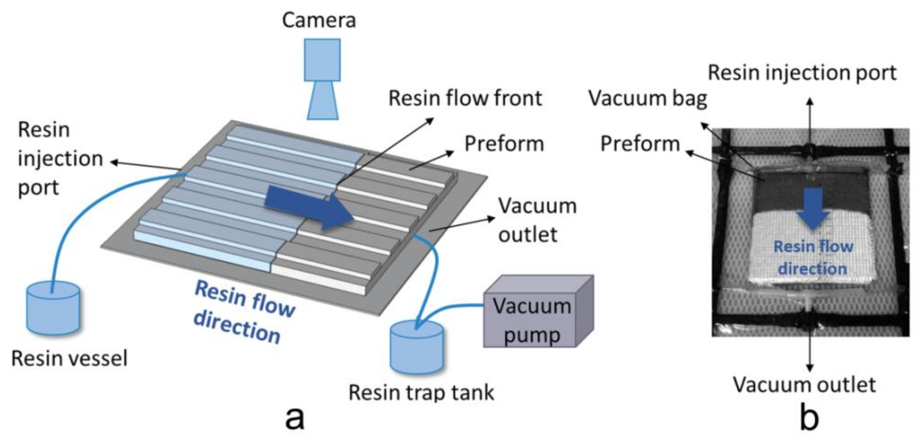
2.3. Permeability Testing Setups
3. Experiment Results and Discussion
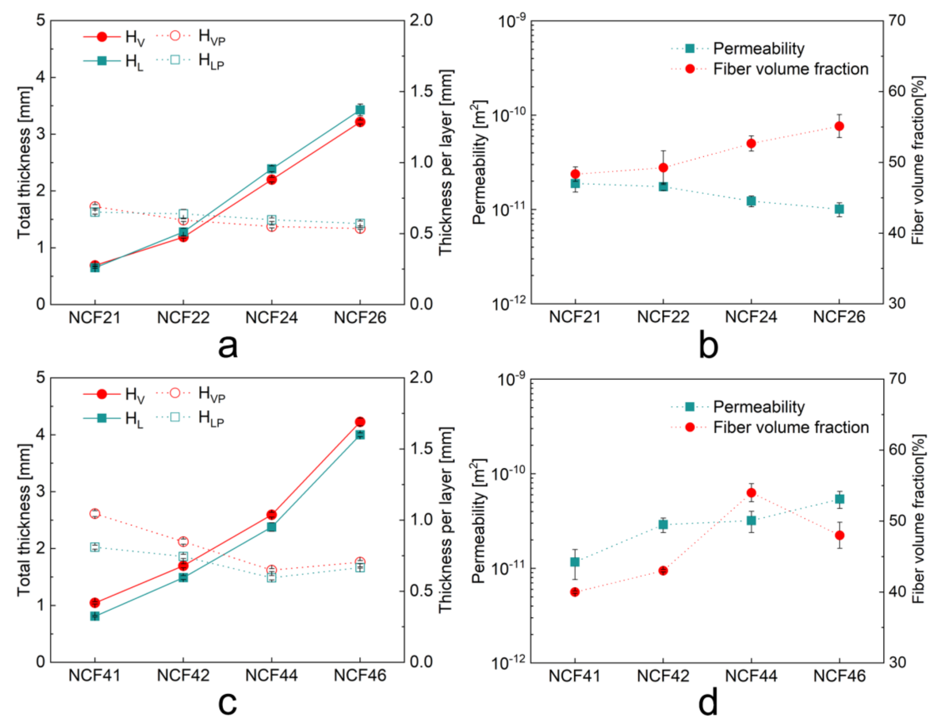
3.1. Compaction Response of Single and Multilayered Preforms
3.2. Permeability of Single and MultiLayered Preforms
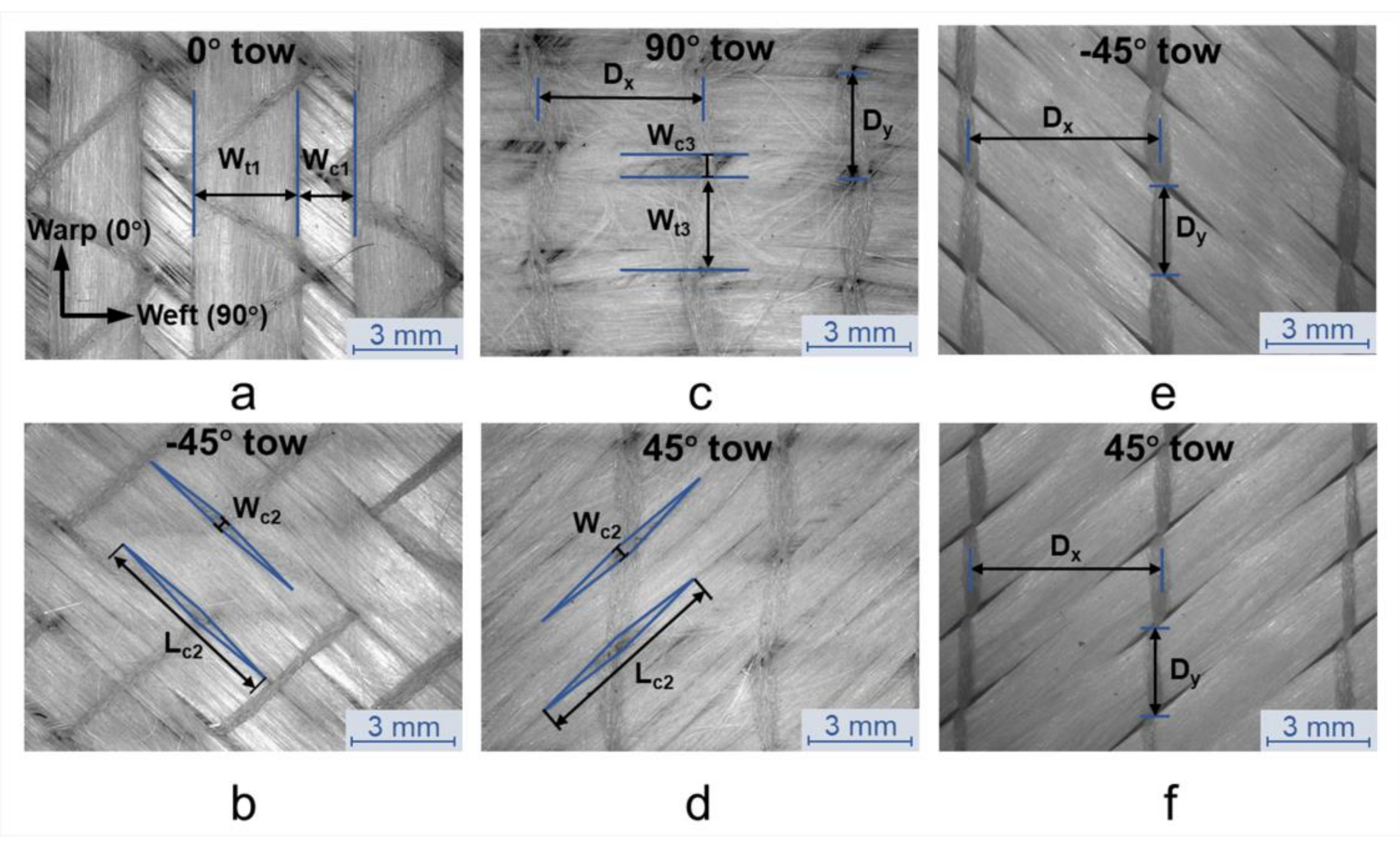
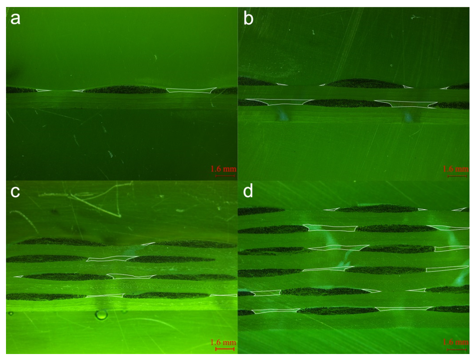
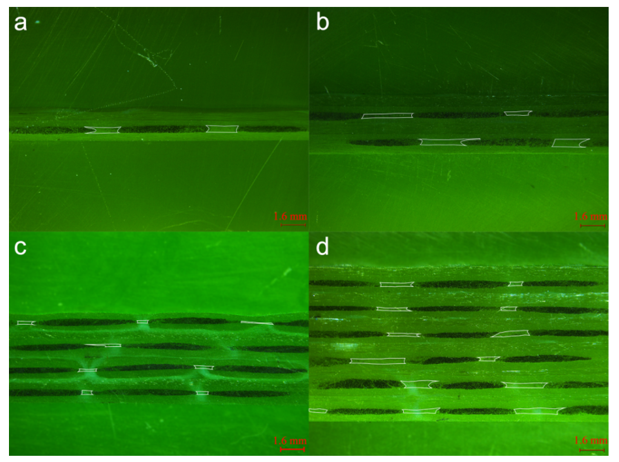
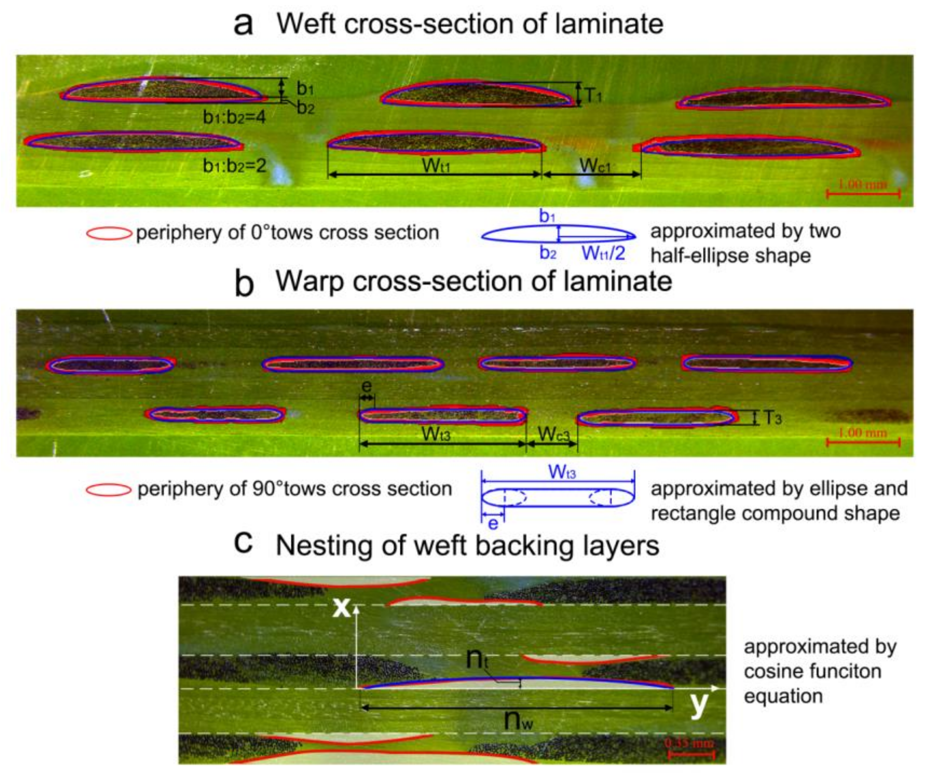
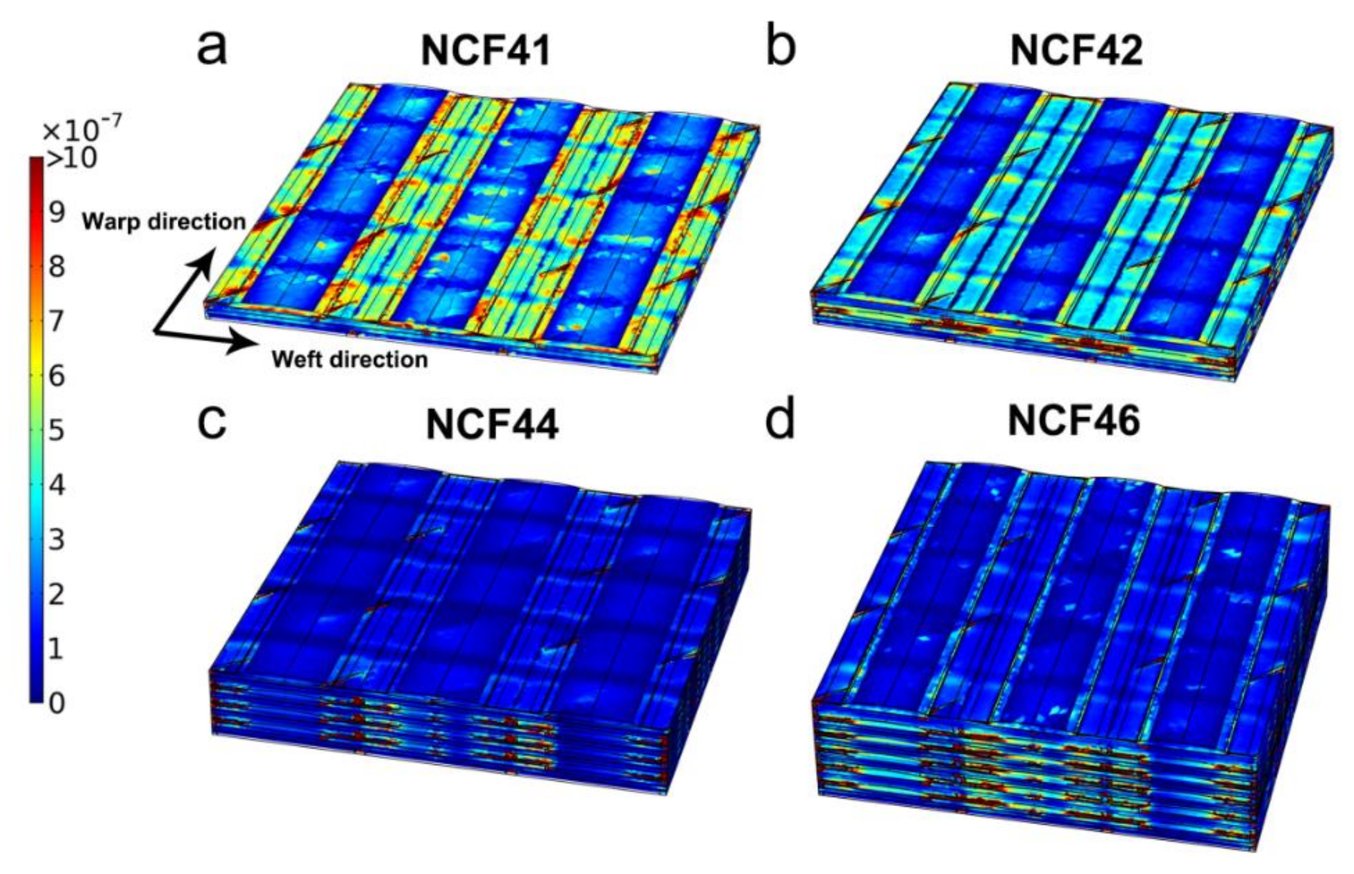
3.3. Internal Geometry of Single and Multilayered Preforms
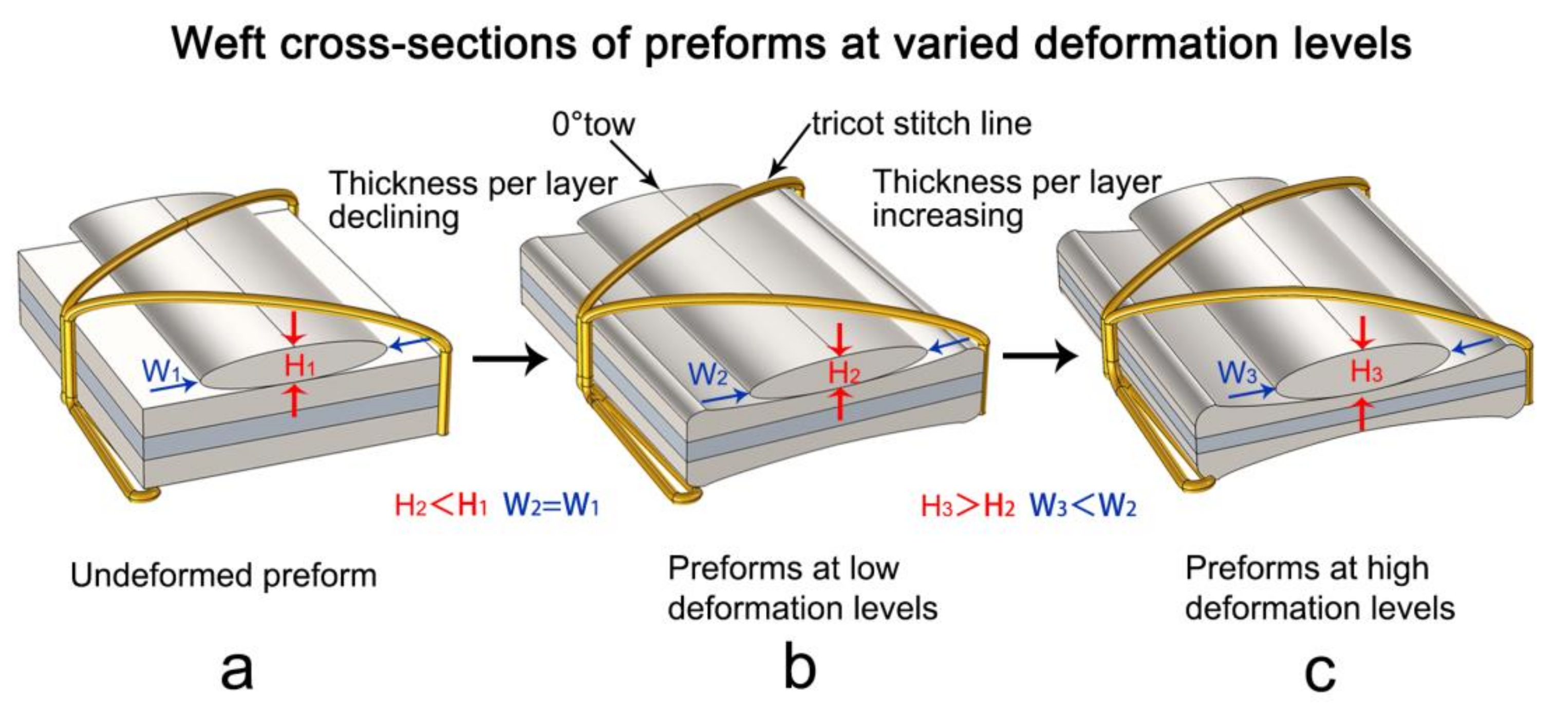
3.4. Compaction Deformation Mechanism of Quadriaxial NCF Preforms
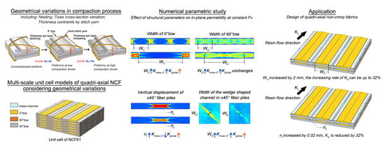
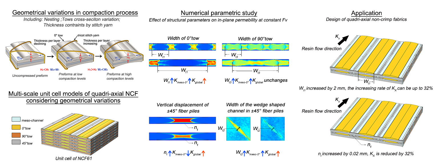
4. Geometrical Modeling of Quadriaxial NCF Preforms
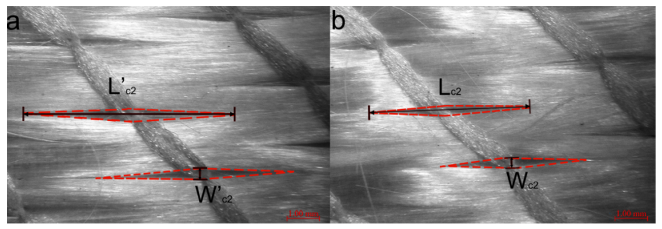
4.1. Modeling the Variations of Local Yarn Cross-Sections
4.2. Modeling the Nesting Deformation of Weft Backing Layers
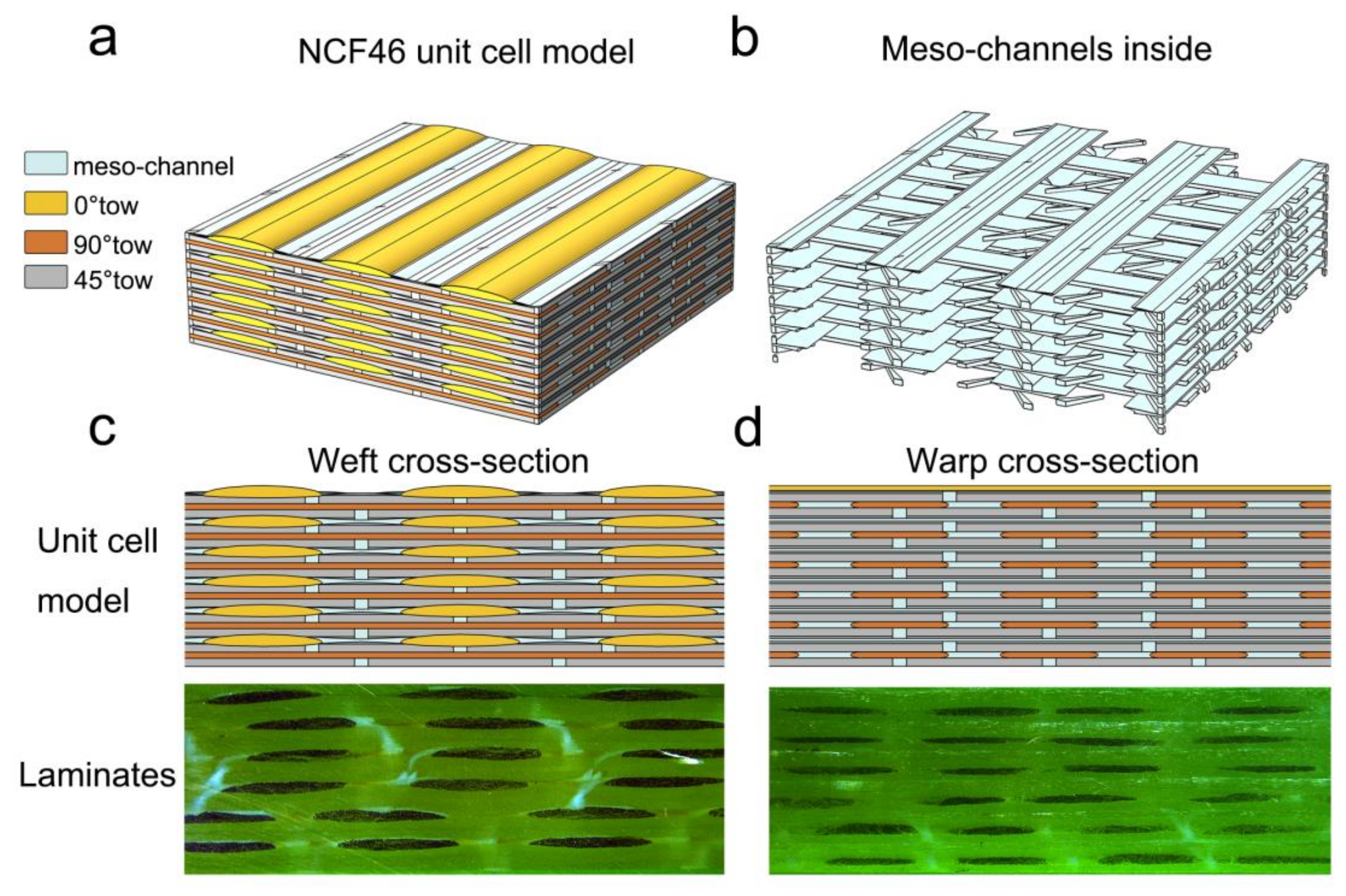
4.3. Unit Cell Generation
5. Permeability Computation
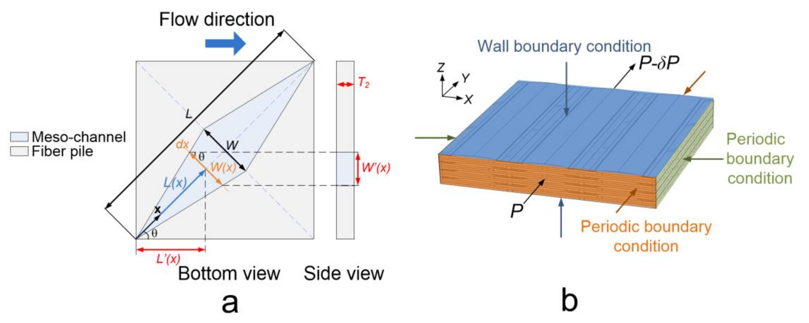
5.1. Fluid Flow Models
5.2. Boundary Conditions
6. Results and Discussion
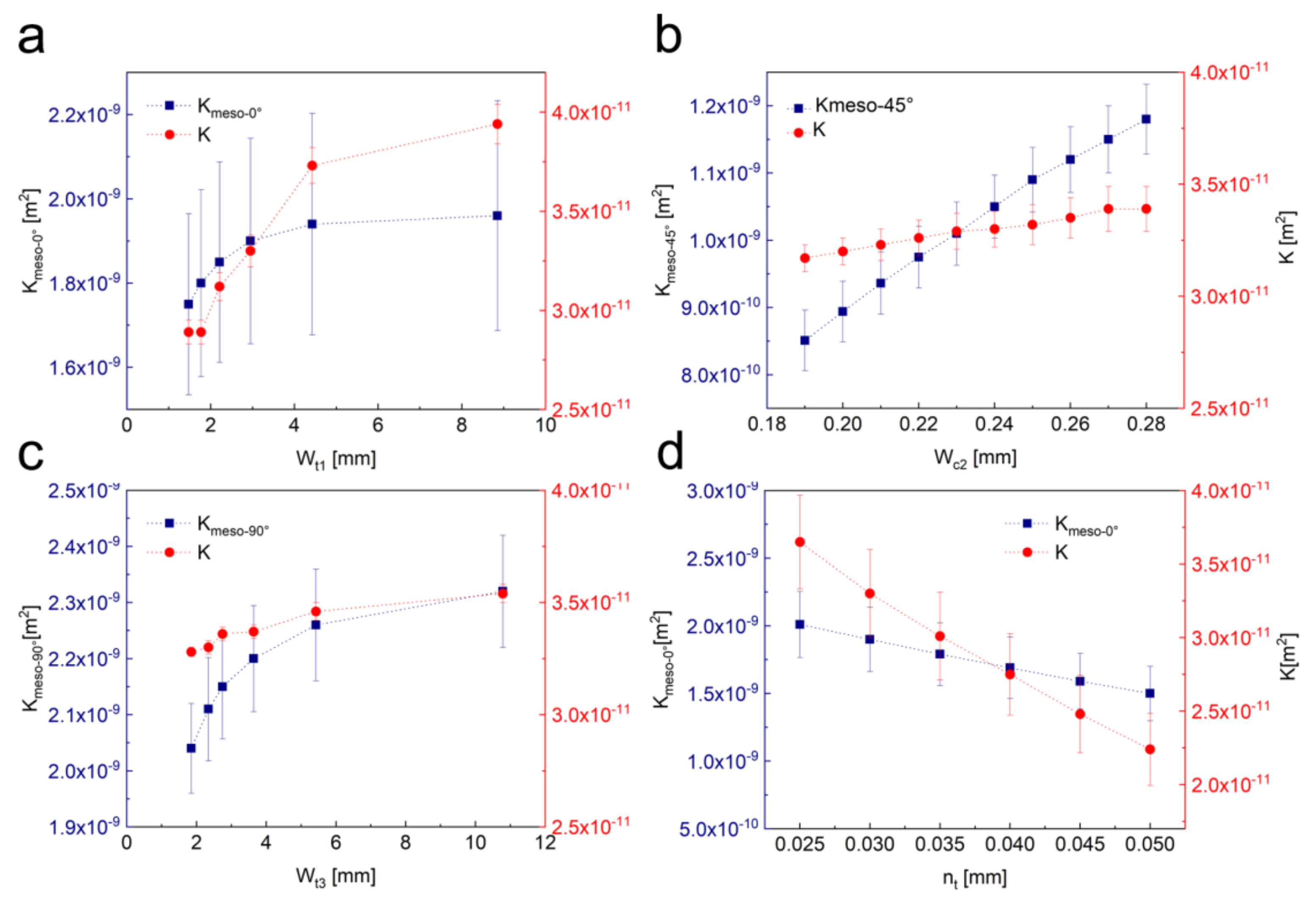
7. Effects of Structural Parameters on the In-Plane Permeability
8. Conclusions
Author Contributions
Funding
Conflicts of Interest
References
- Swery, E.E.; Hans, T.; Bultez, M.; Wijaya, W.; Kelly, P.; Hinterhölzl, R.; Bickerton, S. Complete simulation process chain for the manufacturing of braided composite parts. Compos. Part A Appl. Sci. Manuf. 2017, 102, 378–390. [Google Scholar] [CrossRef]
- Imbert, M.; Abisset-Chavanne, E.; Comas-Cardona, S.; Prono, D. Efficient dual-scale flow and thermo-chemo-rheological coupling simulation during on-line mixing resin transfer molding process. J. Compos. Mater. 2017, 52, 313–330. [Google Scholar] [CrossRef]
- Shou, D.; Ye, L.; Fan, J. Longitudinal permeability determination of dual-scale fibrous materials. Compos. Part A Appl. Sci. Manuf. 2015, 68, 42–46. [Google Scholar] [CrossRef]
- Rouhi, M.S.; Wysocki, M.; Larsson, R. Experimental assessment of dual-scale resin flow-deformation in composites processing. Compos. Part A Appl. Sci. Manuf. 2015, 76, 215–223. [Google Scholar] [CrossRef]
- Rondina, F.; Taddia, S.; Mazzocchetti, L.; Donati, L.; Minak, G.; Rosenberg, P.; Bedeschi, A.; Dolcini, E. Development of full carbon wheels for sport cars with high-volume technology. Compos. Struct. 2018, 192, 368–378. [Google Scholar] [CrossRef]
- Martin, F.A.; Warrior, N.A.; Simacek, P.; Advani, S.; Hughes, A.; Darlington, R.; Senan, E. Simulation and Validation of Injection-Compression Filling Stage of Liquid Moulding with Fast Curing Resins. Appl. Compos. Mater. 2018. [Google Scholar] [CrossRef] [Green Version]
- Kracke, C.; Nonn, A.; Koch, C.; Nebe, M.; Schmidt, E.; Bickerton, S.; Gries, T.; Mitschang, P. Interaction of textile variability and flow channel distribution systems on flow front progression in the RTM process. Compos. Part A Appl. Sci. Manuf. 2018, 106, 70–81. [Google Scholar] [CrossRef]
- Grossing, H.; Fauster, E.; Weninger, M.; Schledjewski, R. Influence of textile parameters on the in-plane permeability characteristics of non-crimped fabric preforms. Polym. Compos. 2016, 37, 1854–1863. [Google Scholar] [CrossRef]
- Vernet, N.; Ruiz, E.; Advani, S.; Alms, J.B.; Aubert, M.; Barburski, M.; Barari, B.; Beraud, J.M.; Berg, D.C.; Correia, N.; et al. Experimental determination of the permeability of engineering textiles: Benchmark II. Compos. Part A Appl. Sci. Manuf. 2014, 61, 172–184. [Google Scholar] [CrossRef] [Green Version]
- Rieber, G.; Jiang, J.H.; Deter, C.; Chen, N.L.; Mitschang, P. Influence of textile parameters on the in-plane Permeability. Compos. Part A Appl. Sci. Manuf. 2013, 52, 89–98. [Google Scholar] [CrossRef]
- Arbter, R.; Beraud, J.M.; Binetruy, C.; Bizet, L.; Breard, J.; Comas-Cardona, S.; Demaria, C.; Endruweit, A.; Ermanni, P.; Gommer, F.; et al. Experimental determination of the permeability of textiles: A benchmark exercise. Compos. Part A Appl. Sci. Manuf. 2011, 42, 1157–1168. [Google Scholar] [CrossRef]
- Zeng, X.; Endruweit, A.; Brown, L.P.; Long, A.C. Numerical prediction of in-plane permeability for multilayer woven fabrics with manufacture-induced deformation. Compos. Part A Appl. Sci. Manuf. 2015, 77, 266–274. [Google Scholar] [CrossRef] [Green Version]
- Endruweit, A.; Zeng, X.; Matveev, M.; Long, A.C. Effect of yarn cross-sectional shape on resin flow through inter-yarn gaps in textile reinforcements. Compos. Part A Appl. Sci. Manuf. 2018, 104, 139–150. [Google Scholar] [CrossRef]
- Martin, B.; Comas-Cardona, S.; Binetruy, C.; Billon, N.; Bouvard, J.L.; Lucas, P. Influence of fabrics’ design parameters on the morphology and 3D permeability tensor of quasi-unidirectional non-crimp fabrics. Compos. Part A Appl. Sci. Manuf. 2016, 90, 470–479. [Google Scholar] [CrossRef]
- Lundström, T.S. The permeability of non-crimp stitched fabrics. Compos. Part A Appl. Sci. Manuf. 2000, 31, 1345–1353. [Google Scholar] [CrossRef]
- Loendersloot, R.; Lomov, S.V.; Akkerman, R.; Verpoest, I. Carbon composites based on multiaxial multiply stitched preforms. Part V: Geometry of sheared biaxial fabrics. Compos. Part A Appl. Sci. Manuf. 2006, 37, 103–113. [Google Scholar] [CrossRef]
- Syerko, E.; Binetruy, C.; Comascardona, S.; Leygue, A. A numerical approach to design dual-scale porosity composite reinforcements with enhanced permeability. Mater. Des. 2017, 131, 307–322. [Google Scholar] [CrossRef]
- Dong, S.H.; Liu, G.; Jia, Y.X.; Li, W.D.; Jiao, X.J. Study on correlation between permeability and structural parameters of non-crimped fabrics. J. Compos. Mater. 2016, 50, 2661–2668. [Google Scholar] [CrossRef]
- Endruweit, A.; Zeng, X.; Long, A.C. Multiscale modeling of combined deterministic and stochastic fabric non-uniformity for realistic resin injection simulation. Adv. Manuf. Polym. Compos. Sci. 2015, 1, 3–15. [Google Scholar] [CrossRef]
- Zeng, X.; Brown, L.P.; Endruweit, A.; Matveev, M.; Long, A.C. Geometrical modelling of 3D woven reinforcements for polymer composites: Prediction of fabric permeability and composite mechanical properties. Compos. Part A Appl. Sci. Manuf. 2014, 56, 150–160. [Google Scholar] [CrossRef]
- Verleye, B.; Lomov, S.V.; Roose, D. 10-Modelling of the permeability of non-crimp fabrics for composites. In Non-Crimp Fabric Composites; Lomov, S.V., Ed.; Cambridgeshire: Woodhead, UK, 2011; pp. 242–260. [Google Scholar] [CrossRef]
- Verleye, B.; Klitz, M.; Croce, R.; Roose, D.; Lomov, S.V.; Verpoest, I. Computation of the permeability of textiles with experimental validation for monofilament and non crimp fabrics. In Computational Textile; Volume 55 of Studies in Computational Intelligence; Zeng, X., Li, Y., Ruan, D., Koehl, L., Eds.; Springer: Berlin/Heidelberg, Germany, 2007; pp. 93–109. [Google Scholar] [CrossRef]
- Frishfelds, V.; Jakovics, A.; Lundstrom, T.S. Automatic recognition and analysis of scanned non-crimp fabrics for calculation of their fluid flow permeability. J. Reinf. Plast. Compos. 2007, 26, 285–296. [Google Scholar] [CrossRef]
- Nordlund, M.; Lundström, T.S.; Frishfelds, V.; Jakovics, A. Permeability network model for non-crimp fabrics. Compos. Part A Appl. Sci. Manuf. 2006, 37, 826–835. [Google Scholar] [CrossRef]
- Lekakou, C.; Edwards, S.; Bell, G.; Amico, S.C. Computer modelling for the prediction of the in-plane permeability of non-crimp stitch bonded fabrics. Compos. Part A Appl. Sci. Manuf. 2006, 37, 820–825. [Google Scholar] [CrossRef]
- Lomov, S.V.; Verpoest, I.; Peeters, T.; Roose, D.; Zako, M. Nesting in textile laminates: Geometrical modelling of the laminate. Compos. Sci. Technol. 2003, 63, 993–1007. [Google Scholar] [CrossRef]
- Haanappel, S.P. Non-crimp fabric permeability modelling. In Proceedings of the 9th International Conference on Flow Processes in Composite Materials, Montréal, QC, Canada, 10 July 2008; pp. 8–10. [Google Scholar]
- Saunders, R.A.; Lekakou, C.; Bader, M.G. Compression in the processing of polymer composites 1. A mechanical and microstructural study for different glass fabrics and resins. Compos. Sci. Technol. 1999, 59, 983–993. [Google Scholar] [CrossRef]
- Hammami, A. Effect of reinforcement structure on compaction behavior in the vacuum infusion process. Polym. Compos. 2001, 22, 337–348. [Google Scholar] [CrossRef]
- Lomov, S.V.; Belov, E.B.; Bischoff, T.; Ghosh, S.B.; Chi, T.T.; Verpoest, I. Carbon composites based on multiaxial multiply stitched preforms. Part 1. Geometry of the preform. Compos. A Appl. Sci. 2002, 33, 1171–1183. [Google Scholar] [CrossRef]
- Yousaf, Z.; Potluri, P.; Withers, P.J. Influence of tow architecture on compaction and nesting in textile preforms. Appl. Compos. Mater. 2017, 24, 337–350. [Google Scholar] [CrossRef]
- Drapier, S.; Monatte, J.; Elbouazzaoui, O.; Henrat, P. Characterization of transient through-thickness permeabilities of Non Crimp New Concept (NC2) multiaxial fabrics. Compos. A Appl. Sci. 2005, 36, 877–892. [Google Scholar] [CrossRef]
- Loendersloot, R. 8-Permeability of non-crimp fabric preforms. In Non-Crimp Fabric Composites; Lomov, S.V., Ed.; Cambridgeshire: Woodhead, UK, 2011; pp. 166–215. [Google Scholar] [CrossRef]
- Hsiao, K.T.; Heider, D. 10-Vacuum assisted resin transfer molding (VARTM) in polymer matrix composites. In Manufacturing Techniques for Polymer Matrix Composites (PMCs); Advani, S.G., Hsiao, K.T., Eds.; Cambridgeshire: Woodhead, UK, 2012; pp. 310–347. [Google Scholar] [CrossRef]
- Govignon, Q.; Bickerton, S.; Morris, J.; Kelly, P. Full field monitoring of the resin flow and laminate properties during the resin infusion process. Compos. A Appl. Sci. 2007, 39, 1412–1426. [Google Scholar] [CrossRef] [Green Version]
- Salvatori, D.; Caglar, B.; Teixidó, H.; Michaud, V. Permeability and capillary effects in a channel-wise non-crimp fabric. Compos. Part A Appl. Sci. Manuf. 2018, 108, 41–52. [Google Scholar] [CrossRef]
- Lundstrom, T.S.; Frishfelds, V.; Jakovics, A. Bubble formation and motion in non-crimp fabrics with perturbed bundle geometry. Compos. Part A Appl. Sci. Manuf. 2010, 41, 83–92. [Google Scholar] [CrossRef]
- Wong, C.C.; Long, A.C.; Sherburn, M.; Robitaille, F.; Harrison, P.; Rudd, C.D. Comparisons of novel and efficient approaches for permeability prediction based on the fabric architecture. Compos. Part A Appl. Sci. Manuf. 2006, 37, 847–857. [Google Scholar] [CrossRef]
- Brinkman, H. A calculation of the viscous force exerted by a flowing fluid on a dense swarm of particles. Appl. Sci. Res. 1949, 1, 27–34. [Google Scholar] [CrossRef]
- Grosan, T.; Postelnicu, A.; Pop, I. Brinkman Flow of a Viscous Fluid Through a Spherical Porous Medium Embedded in Another Porous Medium. Transp. Porous Media 2009, 81, 89. [Google Scholar] [CrossRef]
- Westhuizen, J.; Plessis, J.P.D. Quantification of Unidirectional Fiber Bed Permeability. J. Compos. Mater. 1994, 28, 619–637. [Google Scholar] [CrossRef]
- Gebart, B.R. Permeability of Unidirectional Reinforcements for RTM. J. Compos. Mater. 1992, 26, 1100–1133. [Google Scholar] [CrossRef]
- Åström, B.T.; Pipes, R.B.; Advani, S.G. On Flow through Aligned Fiber Beds and Its Application to Composites Processing. J. Compos. Mater. 1992, 26, 1351–1373. [Google Scholar] [CrossRef]
- Bruschke, M.V.; Advani, S.G. A finite element/control volume approach to mold filling in anisotropic porous media. Polym. Compos. 1990, 11, 398–405. [Google Scholar] [CrossRef]
- Demaría, C.; Ruiz, E.; Trochu, F. In-plane anisotropic permeability characterization of deformed woven fabrics by unidirectional injection. Part I: Experimental results. Polym. Compos. 2007, 28, 797–811. [Google Scholar] [CrossRef]
- Gokce, A.; Advani, S.G. 7-Modeling, optimization and control of resin flow during manufacturing of textile composites with liquid molding. In Design and Manufacture of Textile Composites; Long, A.C., Ed.; Cambridgeshire: Woodhead, UK, 2005; pp. 242–291. [Google Scholar] [CrossRef]


| Fiber System | Fiber Orientation | Geometry | Areal Weight (g·m−2) | Density (Tows·10 cm−1) | Linear Density (tex) | Glass Density (g/cm3) |
|---|---|---|---|---|---|---|
| 1st fiber pile | 0° | unidirectional tows | 212 | 25 | 900 | 2.54 |
| 2nd fiber pile | −45° | weft backing fiber pile | 200 | – | – | 2.54 |
| 3rd fiber pile | 90° | unidirectional tows | 201 | 35 | 500 | 2.54 |
| 4th fiber pile | 45° | weft backing fiber pile | 200 | – | – | 2.54 |
| Fiber System | Fiber Orientation | Geometry | Areal Weight (g·m−2) | Density (Tows·10 cm−1) | Linear Density (tex) | Glass Density (g/cm3) |
|---|---|---|---|---|---|---|
| 1nd fiber pile | −45° | unidirectional tows | 401 | 40 | 700 | 2.54 |
| 2th fiber pile | 45° | unidirectional tows | 401 | 40 | 700 | 2.54 |
| Fabric | Stitch Pattern | Stitch Distance Dx (mm) | Stitch Length Dy (mm) |
|---|---|---|---|
| E-DBLT800-6 | Tricot loop | 4.16 ± 0.12 | 2.5 ± 0.11 |
| E-DB800 | Chain loop | 5.25 ± 0.14 | 2.5 ± 0.09 |
| Test | Fabric | Layups | Stacking Sequences |
|---|---|---|---|
| NCF21 | E-DB800 | 1 | 0 |
| NCF22 | E-DB800 | 2 | [0] 2 |
| NCF24 | E-DB800 | 4 | [0] 4 |
| NCF26 | E-DB800 | 6 | [0] 6 |
| NCF41 | E-DBLT800-6 | 1 | 0 |
| NCF42 | E-DBLT800-6 | 2 | [0] 2 |
| NCF44 | E-DBLT800-6 | 4 | [0] 4 |
| NCF46 | E-DBLT800-6 | 6 | [0] 6 |
| Geometry Parameters of Different Preforms | NCF41 | NCF42 | NCF44 | NCF46 |
|---|---|---|---|---|
| Width of 0° tows Wt1 (mm) | 2.99 ± 0.06 | 2.86 ± 0.16 | 2.95 ± 0.14 | 2.71 ± 0.15 |
| Width of the meso-channel between 0° tows Wc1 (mm) | 1.49 ± 0.21 | 1.36 ± 0.19 | 1.26 ± 0.10 | 1.54 ± 0.28 |
| Height of 0° tows T1 (mm) | 0.289 ± 0.008 | 0.267 ± 0.03 | 0.202 ± 0.03 | 0.275 ± 0.02 |
| Maximum Vertical displacement of ±45° fiber piles due to nesting nt (mm) | 0.06 ± 0.01 | 0.025 ± 0.01 | 0.03 ± 0.02 | 0.04 ± 0.02 |
| Horizontal spread width of the nested section nw (mm) | 1.42 ± 0.21 | 1.26 ± 0.19 | 1.16 ± 0.10 | 1.45 ± 0.28 |
| The width of the meso-channels on ±45° fiber piles Wc2 (mm) | 0.24 ± 0.01 | 0.25 ± 0.01 | 0.23 ± 0.02 | 0.24 ± 0.01 |
| The height of the meso-channels on ±45° fiber piles Lc2 (mm) | 2.74 ± 0.20 | 2.8 ± 0.15 | 2.62 ± 0.20 | 2.76 ± 0.31 |
| Height of ±45° fiber piles T2 (mm) | 0.189 ± 0.025 | 0.185 ± 0.02 | 0.162 ± 0.04 | 0.162 ± 0.05 |
| Width of 90° tows Wt3 (mm) | 2.34 ± 0.12 | 2.05 ± 0.185 | 2.39 ± 0.23 | 2.15 ± 0.18 |
| Width of the meso-channel between 0° tows Wc3 (mm) | 1.03 ± 0.14 | 1.37 ± 0.08 | 1.15 ± 0.17 | 1.28 ± 0.23 |
| Major axis length of the ellipse in the compound fitting shape e (mm) | 0.15 | 0.15 | 0.2 | 0.2 |
| Height of 90° tows T3 (mm) | 0.166 ± 0.013 | 0.138 ± 0.023 | 0.126 ± 0.018 | 0.126 ± 0.025 |
| The fiber volume fraction of tows Vf-tow | 0.5 ± 0.02 | 0.54 ± 0.02 | 0.63 ± 0.03 | 0.58 ± 0.03 |
| Fiber diameter (μm) | 17 ± 3 | 17 ± 3 | 17 ± 3 | 17 ± 3 |
| Unit Cells of Different Preforms | NCF41 | NCF42 | NCF44 | NCF46 |
|---|---|---|---|---|
| S (mm) | 13.5 | 13.5 | 13.5 | 13.5 |
| Wt1 (mm) | 2.95 ± 0.15 | 2.95 ± 0.15 | 2.95 ± 0.15 | 2.71 ± 0.15 |
| Wc1 (mm) | 1.55 ± 0.15 | 1.55 ± 0.15 | 1.55 ± 0.15 | 1.79 ± 0.15 |
| T1 (mm) | 0.289 | 0.267 | 0.202 | 0.275 |
| nt (mm) | 0.06 ± 0.01 | 0.03 ± 0.01 | 0.03 ± 0.02 | 0.05 ± 0.02 |
| nw (mm) | 1.55 ± 0.15 | 1.55 ± 0.15 | 1.55 ± 0.15 | 1.79 ± 0.15 |
| Wc2 (mm) | 0.24 | 0.24 | 0.24 | 0.24 |
| Lc2 (mm) | 2.74 | 2.74 | 2.74 | 2.74 |
| T2 (mm) | 0.189 | 0.185 | 0.162 | 0.162 |
| Wt3 (mm) | 2.34 | 2.34 | 2.34 | 2.34 |
| Wc3 (mm) | 1.035 | 1.035 | 1.035 | 1.035 |
| e (mm) | 0.15 | 0.15 | 0.2 | 0.2 |
| T3 (mm) | 0.166 | 0.138 | 0.126 | 0.126 |
| Vf-tow | 0.5 | 0.54 | 0.63 | 0.58 |
| Fiber diameter(μm) | 17 | 17 | 17 | 17 |
| Unit Cells of Different Preforms | Kmicro-0° (m2) | Kmeso-0° (m2) | Kmicro-45° (m2) | Kmeso-45° (m2) | Kmicro-90° (m2) | Kmeso-90° (m2) |
|---|---|---|---|---|---|---|
| NCF41 | 5.45*10−12 | 1.63*10−9 ± 3.30*10−10 | 3.32*10−10 | 1.08*10−9 | 1.18*10−12 | 3.01*10−9 |
| NCF42 | 3.64*10−12 | 2.11*10−9 ± 4.50*10−10 | 2.22*10−12 | 1.05*10−9 | 7.95*10−13 | 2.11*10−9 |
| NCF44 | 1.39*10−12 | 9.35*10−9 ± 3.49*10−10 | 8.45*10−13 | 8.98*10−10 | 2.98*10−13 | 1.73*10−9 |
| NCF46 | 2.40*10−12 | 2.28*10−9 ± 6.60*10−10 | 1.46*10−12 | 8.98*10−10 | 5.24*10−13 | 1.73*10−9 |
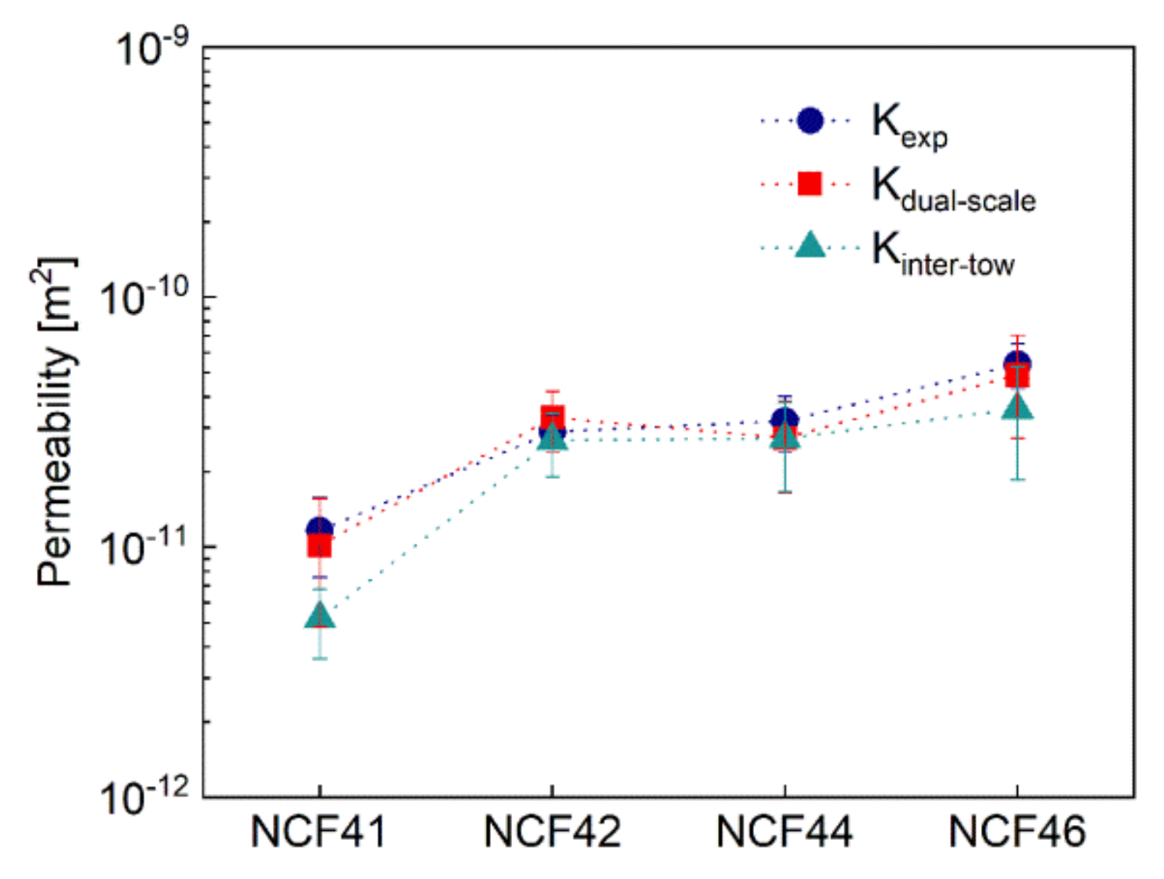
| Preforms | Permeability Tested in Experiment /m2 | Predicted Permeability/m2 | Error/ |Kpredicted-Kexperiment|/Kexperiment |
|---|---|---|---|
| NCF41 | 1.17*10−11 ± 4.09*10−12 | 1.02*10−11±5.40*10−12 | 12.8% |
| NCF42 | 2.9*10−11 ± 5.09*10−12 | 3.30*10−11± 9.10*10−12 | 13.8% |
| NCF44 | 3.2*10−11 ± 8.13*10−12 | 2.74*10−11 ± 1.09*10−11 | 14.4% |
| NCF46 | 5.4*10−11 ± 1.11*10−11 | 4.89*10−11 ± 2.16*10−11 | 9.4% |
© 2020 by the authors. Licensee MDPI, Basel, Switzerland. This article is an open access article distributed under the terms and conditions of the Creative Commons Attribution (CC BY) license (http://creativecommons.org/licenses/by/4.0/).
Share and Cite
Geng, Y.; Jiang, J.; Lin, F.; Shao, H.; Zhang, C.; Chen, N. Study of Compaction Properties and Permeability Prediction of Multilayered Quadriaxial Non-Crimp Fabric in Liquid Composite Molding Process. Polymers 2020, 12, 1525. https://doi.org/10.3390/polym12071525
Geng Y, Jiang J, Lin F, Shao H, Zhang C, Chen N. Study of Compaction Properties and Permeability Prediction of Multilayered Quadriaxial Non-Crimp Fabric in Liquid Composite Molding Process. Polymers. 2020; 12(7):1525. https://doi.org/10.3390/polym12071525
Chicago/Turabian StyleGeng, Yi, Jinhua Jiang, Fangbing Lin, Huiqi Shao, Chenglong Zhang, and Nanliang Chen. 2020. "Study of Compaction Properties and Permeability Prediction of Multilayered Quadriaxial Non-Crimp Fabric in Liquid Composite Molding Process" Polymers 12, no. 7: 1525. https://doi.org/10.3390/polym12071525