Article

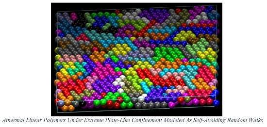
Self-Avoiding Random Walks as a Model to Study Athermal Linear Polymers under Extreme Plate Confinement

Institute for Optoelectronic Systems and Microtechnology (ISOM) and Escuela Técnica Superior de Ingenieros Industriales (ETSII), Universidad Politecnica de Madrid (UPM), José Gutierrez Abascal 2, 28006 Madrid, Spain
*
Author to whom correspondence should be addressed.
Polymers 2020, 12(4), 799; https://doi.org/10.3390/polym12040799
Submission received: 3 March 2020 / Revised: 24 March 2020 / Accepted: 25 March 2020 / Published: 3 April 2020
(This article belongs to the Special Issue Theory of Polymers at Interfaces)

Abstract

:
Monte Carlo (MC) simulations, built around chain-connectivity-altering moves and a wall-displacement algorithm, allow us to simulate freely-jointed chains of tangent hard spheres of uniform size under extreme confinement. The latter is realized through the presence of two impenetrable, flat, and parallel plates. Extreme conditions correspond to the case where the distance between the plates approaches the monomer size. An analysis of the local structure, based on the characteristic crystallographic element (CCE) norm, detects crystal nucleation and growth at packing densities well below the ones observed in bulk analogs. In a second step, we map the confined polymer chains into self-avoiding random walks (SAWs) on restricted lattices. We study all realizations of the cubic crystal system: simple, body centered, and face centered cubic crystals. For a given chain size (SAW length), lattice type, origin of SAW, and level of confinement, we enumerate all possible SAWs (equivalently all chain conformations) and calculate the size distribution. Results for intermediate SAW lengths are used to predict the behavior of long, fully entangled chains through growth formulas. The SAW analysis will allow us to determine the corresponding configurational entropy, as it is the driving force for the observed phase transition and the determining factor for the thermodynamic stability of the corresponding crystal morphologies.

Graphical Abstract

1. Introduction

Polymer based thin films have been used extensively for several decades in a varied range of applications from optical coatings and energy storage to smart appliances, semiconductors and pharmaceutics [1,2,3,4,5,6,7,8,9,10,11,12,13,14,15,16,17,18,19]. Further inclusion of nanoparticles or adhesion to complex interfaces allows efficient control, tuning, and magnification of the already exceptional base macromolecular properties. To achieve superior characteristics, it is paramount to understand the complex structural and dynamic behavior of macromolecules, ideally at the level of atoms and molecules, under confinement and to relate them with macroscopic properties of the end material.
Especially relevant for numerous applications is the phase behavior, as macromolecular crystals exhibit distinctly different characteristics compared to polymer glasses. While phase transition, as observed in complex atomic systems, is extensively studied it is still far from being fully understood. The early work of Alder and Wainwright, based on collision-driven molecular dynamics (MD), demonstrated that monomeric hard spheres crystallize at high concentrations [20]. It is now established that given enough observation time, hard spheres or corresponding colloidal entities show spontaneous crystallization under a variety of conditions (microgravity, impurities, size polydispersity etc) once a critical range of packing densities is reached [21,22,23,24,25,26,27,28,29,30,31,32,33,34,35,36,37,38,39,40,41,42]. Given the athermal nature of such systems, entropy is the driving force of crystal nucleation and growth and dictates the resulting, thermodynamically stable, ordered morphologies. Recently, it has been demonstrated that dense packing of chains of hard spheres also crystallize [43,44,45,46]. It is possible to effectively control the phase behavior and/or the state of jamming [47,48,49,50] for polymers by properly tuning the bond gaps (or bond tangency) between successive monomers along the chain [51,52] or the bending angles that dictate chain flexibility [53,54]. Similar control can be achieved by applying spatial confinement; in the most trivial case this can be realized through the presence of flat, impenetrable, and parallel walls in at least one dimension.
In the past, we used a Monte Carlo (MC) scheme [55], built around chain-connectivity-altering MC moves [56,57,58,59], to generate and equilibrate freely-jointed chains of hard spheres of uniform size in the bulk. This allowed us to systematically study the effect of packing density, chain length and bond tangency/gaps on the local and global structure of athermal macromolecules [48,60,61], on the primitive path network of entanglements [49,62] and on the ability of chains to crystallize [43,44,45,46,52]. Recently, based on the original scheme of Ref. [55], we introduced a more general method including a wall-displacing algorithm which allows the simulation of athermal polymer packings under confinement [63]. This more general method has allowed us to simulate systems of very long chains under extreme confinement and at very high packing density and at high cell shape anisotropy. For the linear chains considered here the number of monomers is, Nmon = N + 1, where N is the number of bonds. Confining agents are flat, parallel and impenetrable surfaces (walls). Packing density, ϕ, is defined as the volume occupied by all chain monomers divided by the volume of the simulation cell. The number of confined dimensions, dconf, ranges from zero (unconstraint, bulk case) to three (fully confined). Extreme confinement is reached when the distance between the walls, dwall, in at least one dimension approaches the size of sphere monomers, σ. Cell shape anisotropy is quantified through the cell aspect ratio, ζ, which is the ratio of longest length(s) divided by the shortest one(s). In all cases cell shape corresponds to an orthogonal parallelepiped.
Through the proposed MC scheme we equilibrate dense athermal chain packings under extreme confinement that correspond to quasi-1D (tube-like) and quasi-2D (plate-like) polymer thin films [63]. In both cases as a critical combination of concentration and confinement is reached polymers transit to ordered morphologies characterized by structural defects. For plate-like packings this ordered state is a blend of hexagonal close packed (HCP) and face centered cubic (FCC) domains. Given that the system is athermal, any phase transition is driven by a change (increase) in the total entropy. Accordingly, to predict the phase transitions and to identify the thermodynamically stable phase, a first step is to calculate the configurational entropy of chains. Towards this, we map the corresponding atomistic chains onto self-avoiding random walks (SAWs) grown step-by-step on regular lattices subject to specific spatial restrictions. During the growth, the next position to lattice has to be adjacent to the current one. Self-avoidance condition dictates that no lattice point can be visited twice. In addition, the imposed spatial restrictions on SAW lattices mimic the ones encountered at the atomistic level. In a previous paper we enumerated the total number of SAWs for two different lattices SC (simple cubic) and FCC as a function of the system geometry and the number of chain bonds (or equivalently SAW steps) for quasi-1D, tube-like morphologies [64]. Here, we employ the same methodology to identify the SAW number and size distribution in quasi-2D, plate-like polymer films. Apart from the direct enumeration for moderately long chains our goal is to provide the scaling exponents in the growth formulas that can be used to predict the SAW behavior as a function of chain size, crystal structure, and level of confinement for significantly longer chains.
The concept of random walk is central to stochastic processes and is applicable to a very wide range of scientific fields and research topics from mathematics, economics, image processing, and social networks to computer science, biology, genetics, and materials [65,66,67,68,69,70,71,72,73,74,75,76,77,78,79,80,81,82,83,84,85,86,87,88,89,90,91]. Self-avoiding random walks have been used extensively to study randomness as observed in kinetics, dynamics, propagation, growth, percolation phenomena and molecular conformations in soft matter [92,93,94,95,96,97,98]. Of particular importance is the SAW model in polymer science as it is directly related to the free-flight models describing chain conformations under various conditions (bulk, confinement, surface adsorption, non-linear chain architecture, chain flexibility, nanofillers etc.) [99,100,101,102,103,104,105,106,107,108,109,110,111,112,113,114,115,116,117,118,119,120,121]. From the technical perspective, since the early work of Orr [112], significant progress has been made towards the development of algorithms that allow efficient SAW enumeration and calculation of the critical exponents in scaling expressions [87,122,123,124,125,126,127,128,129,130,131,132,133]. These are important algorithmic milestones in the SAW enumeration problem that becomes more than exponentially difficult as the number of steps increases.

2. Materials and Methods

In a first step, Monte Carlo simulations have been conducted using the algorithm described in Ref. [63] to generate and successively equilibrate freely-jointed chains of tangent hard spheres of uniform size under plate-like confinement (dconf = 1). Average chain lengths range from Nmon = 8 to 1000 and packing densities from ϕ = 0.20 to 0.55. We recall here that the freezing and melting points for monomeric hard spheres in the bulk correspond to 0.494 and 0.545, respectively. For chains of tangent hard spheres in the bulk, given the crucial effect of bond tangency/gaps [51,52], the melting point is delayed until a concentration range of ϕ ≈ 0.58 is reached [43,44,45,46].
Initial system configurations correspond to cubic cells (ζ = 1) under full confinement (dconf = 3) which have been generated at dilute conditions and compressed through the wall-displacement (MRoB) algorithm [63] until the desired volume fraction is reached. Then, MRoB is further employed to progressively increase the cell aspect ratio. This process results in the inter-wall distance, Dwall, being reduced until the limit of extreme confinement Dwall → σ. System configurations are generated at regular intervals during the box transformation phase. Subsequent long MC simulations undertake the task of equilibration with a duration that exceeds hundreds of billions of steps.
As will be demonstrated in the continuation flexible chains, under extreme plate-like confinement, crystallize into well-defined patterns at concentrations significantly lower than the ones in the bulk. Based on this, in the second phase we map the flexible polymer chain onto a SAW on restricted lattice. Here, we follow the original concept presented by Benito et al. [64] according to which in such spatially restricted polymer crystals monomers adopt positions which closely approach the sites of regular lattices. Accordingly, information on the configurational entropy of the freely-jointed chains in plate-like templates can be extracted by analyzing the corresponding SAWs on restricted crystal lattices under the same geometry and conditions (SAW length, lattice type).
We enumerate all possible distinct SAWs on regular lattices corresponding to cubic crystals (SC, BCC and FCC with coordination numbers 6, 8, and 12, respectively). The reference case is the unrestricted one: SAWs on bulk systems under periodic boundary conditions applied in all dimensions. For the bulk lattices and given a specific chain model (i.e., fully flexible one) the number of distinct SAW configurations, cN, and the average SAW size, as quantified through the mean square end-to-end distance | ω N | 2 , depend solely on the number of SAW steps, N. However, by introducing plate-like confinement, the spatial group symmetry of the original unrestricted system is reduced from the original Ia 3 ¯ d. As a result of this, and of the heterogeneity of the confined system, three additional parameters must be considered: level (or intensity) of confinement, the relative orientation of the regular lattice with respect to the axis of confinement, and the initial position (origin) of the SAW, which will be referenced to as “Type” throughout the manuscript. The confinement level can be expressed in terms of the number of crystal layers, n, between the parallel plates or as the corresponding inter-plate distance, Dwall, measured in units of the SAW step length.
The inclusion of the SAW origin (or Type) parameter is a result of the spatial restrictions and the break of symmetry imposed by the plate confinement: the symmetry of Ia 3 ¯ d of the bulk case is reduced to I41/acd due to the presence of the flat, impenetrable walls along the confined dimension. As in Ref. [64] the orientation of the plate axis is defined by direction indices according to the crystallographic practice: [ijk]. Given that the crystalline domains are formed with their orientation aligned along the plate section the confining plates are contained in the planes of the crystallographic form [100]. Effectively, a SAW grows on a restricted lattice, RL(Dwall) defined as:
R L ( D ) = { x _ |   x 1 ,   x 2 Z ,   | x 3 | < D wall   }
where x _ defines the coordinates of every lattice node and Z is the unit hypercube of dimension one. Due to the symmetry of the cubic system any axis can be designated as the confined one, denoted in the equation above as x3. The enumeration process and successive analysis take into account the SAW Type as an additional system parameter: For a given number of steps SAWs starting from origins close to the plate boundaries are expected to show smaller cN number than the ones growing far from them. Figure 1 shows various cases of plate confinement and the corresponding distinction of lattice sites belonging to different types. For simplicity, a 2-D square lattice is displayed with a varied number of layers, n. For the cubic (or square) lattice the number of layers coincides with the inter-plate distance (measured in units of SAW step length). However, this is not the case for the BCC and FCC lattices. Due to symmetry, all nodes that belong to the same layer are characterized by the same Type. Layers are colored according to their Type (SAW origin), which in turn depends on the distance from the closest confining boundary. For example, for n = 2, two layers of lattice points exist but both correspond to the same SAW Type as they are similarly adjacent to a different plate wall. The value n = 3 leads to two different SAW origins, one in the center and one touching the wall. In general, for the cubic crystal system (SC, BCC and FCC) under plate confinement for even values of the number of layers, n, there exist in total n/2 distinct SAW Types, while for odd ones the corresponding number changes to (n − 1)/2 + 1. In the present work, the assignment of Type starts from the layers adjacent to the walls (Type 1) and ends at the ones in the middle. In Figure 1 for n = 6, red (closest to the confining plates), green and yellow (furthest from the confining planes) layers have been assigned Types of 1, 2, and 3, respectively. Multiplicity corresponds to the number of crystallographically equivalent restricted lattices points. For even numbers of n all Types have a multiplicity equal to 2, and the same is true for odd numbers with the only exception being the points of the central layer which show cardinality of unity. Multiplicity of SAW Type is important to determine symmetry as it effectively reduces the number of studied systems and the corresponding computational time in SAW enumeration.
A distinction between the different lattices of the cubic system can be established once the number of layers between plates becomes equal or exceeds 2. Obviously, the most extreme case corresponds to a single layer under confinement, i.e., n = 1. In such 2-D templates the corresponding lattices, studied in the present work, are honeycomb (coordination number of 3), square (coordination number of 4) and triangular (coordination number of 6) as seen in Figure 2.
To summarize, for the given chain architecture (fully flexible linear chains) the number and size of SAWs depend on (i) number of steps, N, (ii) lattice type, (iii) level of plate confinement, quantified primarily here through the number of crystal layers between the parallel plates, n and (iv) Type (point of SAW origin). The parametric analysis per regular lattice is as follows: SC: N ∈ [1, 18], n ∈ [1, 5]; BCC: N ∈ [1, 15], n ∈ [1, 5]; FCC: N ∈ [1, 13], n ∈ [1, 5]. Obviously, in direct enumeration for a fixed number of SAW steps computational time increases as the coordination number of the lattice increases. Accordingly, the longest chains were accessed for the SC lattice and the shortest SAWs were modeled for the FCC crystal.
In total 376 different 3-D systems were studied: 150 for SC, 117 for BCC and 109 for FCC restricted lattices. In the most extreme case, corresponding to 2-D polymer films, 58 systems were studied: 25 for the honeycomb, 18 for the square, and 15 for the triangular lattices. The main parameters of the modeled systems are reported in Table 1. A home-made SAW code for direct enumeration was developed and all simulations were conducted on Linux-based Intel i7-8700K CPU architectures with 32 Gb of memory.

3. Results

3.1. Monte Carlo Simulations

Snapshots at the end of the MC equilibration for the Nmon = 12 system can be seen in Figure 3. The system contains 100 chains with a minimum and maximum chain length of 8 and 16, respectively, at ϕ = 0.50 under unidimensional, plate confinement (dconf = 1) and for various cell aspect ratios. The packing density ϕ = 0.50 of all structures in Figure 3 is well below the transition point for athermal chains in the bulk (ϕ ≈ 0.58). Still, as can be seen from a visual inspection of the bottom-right panel of Figure 3, which corresponds to extreme confinement (ζ = 12 and Dwall = 2), monomers on both surfaces show very clear signs of ordering.
Crystal nucleation and growth can be accurately identified and then quantified by applying the characteristic crystallographic element (CCE) norm, which is able to distinguish between different competing crystal structures [44,135,136]. As the athermal chain packings correspond to high concentration, we employ the CCE norm with respect to the FCC and HCP crystals as well as the fivefold local symmetry. The CCE norm is applied on all sites/monomers present in the system. Once the value of the CCE norm with respect to a specific crystal X, εX, is lower than a critical threshold (εX < 0.245), the site is identified as of X similarity. Due to the distinguishing nature of the crystallographic elements, no site can possess dual crystal similarity. Figure 4 hosts configurations, as the MC simulation evolves, for the 10-chains Nmon = 1000 system at ϕ = 0.55 (still quite below the bulk melting point of athermal polymers), showing only monomers with HCP (blue), FCC (red) and fivefold (green) local environment. All other sites, labeled as “amorphous”, are not shown for clarity purposes. Starting from the initially amorphous state (upper panel), the system shows a clear disorder–order transition with the stable crystal increasing in size as the observation time increases. The final stable configuration is highly close packed with predominant HCP character.

3.2. Verification with Available Literature Data

As mentioned in Section 2, centers of the spherical monomers adopt positions that resemble closely nodes of a perfect crystal. For example, this tendency is particularly evident for the case shown in the bottom-right panel of Figure 3. Thus, we model linear flexible polymers in confined space as self-avoiding random walks on restricted lattices.
First, results are compared against literature data on the well-studied SAWs on bulk 3-D SC, BCC and FCC lattices and on most extremely confined ones that correspond to 2-D lattices (HON, SQU and TRI). The unrestricted (bulk) case can be modeled either by removing any spatial conditions related to confinement or by having the number of lattice layers, n, to be larger than the maximum possible chain extension, i.e. n > N + 1. Data on the number of distinct SAWs, cN, and on the mean square end-to-end distance, | ω N | 2 , as a function of SAW steps, N, can be found in Table A1 and Table A2 of the Appendix A for the extremely confined 2-D and the unrestricted 3-D lattices, respectively. For all regular lattices studied here extreme confinement (n = 1) involves a single SAW origin (Type 1); the same is true for the 3-D bulk cases due to symmetry considerations. Results for the bulk SC and FCC lattices are in perfect quantitative agreement with our past work conducted through a different numerical algorithm [64]. Furthermore, for both SAW populations and average sizes our enumeration data coincide with the ones in Refs. [131] and [132] for SC; in Ref. [133] for bulk BCC and FCC; in Ref. [137] for the 2-D triangular and in Ref. [128] for square, honeycomb, and SC lattices. We should note here that, given the large number of systems to be studied (three different lattice types, different Types and levels of confinement), our goal is not to exceed or even reach the current state-of-the-art in modeled SAW lengths but rather to establish asymptotic scaling formulas for the confined cases. These will allow us to predict the behavior of long SAWs (and equivalently of long chains) from results on short or intermediate ones and establish a systematic connection between plate-like confinement and properties of the corresponding SAWs. Table A3, Table A4, Table A5, Table A6, Table A7, Table A8, Table A9, Table A10, Table A11 and Table A12 host the properties of SAWs (cN and | ω N | 2 ) for all confined lattices with the number of layers between plates lying in the interval n ∈ [2, 5]. An interesting trend can be observed for the BCC lattice with n = 2 (Table A3): the number of distinct SAWs coincides with the one extracted for the SQU lattice (Table A1). This is because with respect to connectivity there is no distinction between the square and the 2-layer BCC lattices.

3.3. Direct SAW Enumeration

Data (cN vs. N and | ω N | 2 vs. N) as presented in Table A1, Table A2, Table A3, Table A4, Table A5, Table A6, Table A7, Table A8, Table A9, Table A10, Table A11 and Table A12, obtained from SAWs of short to intermediate length, can be used in the asymptotic formulas [131,133,137] for the scaling of the number of distinct SAWs in the limit of N → ∞:
c N ~ A μ N N γ 1
and of the mean-square, end-to-end distance:
| ω N | 2 ~ D N 2 v
where γ and υ are the critical exponents, A and D are the critical amplitudes, and μ is the connective constant. While A, D, and μ depend on lattice type the critical exponents γ and υ are considered universal [133,137,138,139]. As proven by Duminil-Copin and Smirnov [140] the connective constant for the honeycomb lattice is equal to μ = 2 + 2 , as originally conjectured by Nienhuis [141,142].
Figure 5, Figure 6 and Figure 7 present the logarithm of the number of distinct SAWs versus the logarithm of the number of SAW steps for the restricted SC, BCC, and FCC lattices, respectively. For all systems studied here, the combination of SAW size (chain length) and applied confinement force the self-avoiding random walks to “feel” the imposed spatial constraints. In all cases the obvious trend is fully established: the stronger the restrictions imposed by the film-like confinement the smaller the number of available SAWs, or equivalently, the fewer the number of distinct chain configurations and accordingly reduced configurational entropy. The most extremely confined system (n = 1 for SC (SQU) or n = 2 for BCC and FCC) is the one that deviates markedly from the unrestricted bulk case. As film thickness (inter-plate distance) increases SAW properties converge to the ones in the bulk. Between different Types, the lattice nodes and layers lying closer to the confining surfaces are characterized systematically by smaller cN than the ones near the center. This is manifestly valid for the SC and FCC lattices, but not always true for the BCC, as can be readily observed by comparing the different Type columns in the Appendix A Tables. This difference in trends can be explained by the coordination number which remains the same for SC but depends on the layer index for BCC. In general, the effect of SAW origin (Type) on SAW properties is smaller in plate-like (quasi 2-D) confinement, as established here, than in tube-like (quasi 1-D) restricted lattices, as reported in Ref. [64].
Comparing the different restricted lattices of the cubic system trends analogous to the bulk case are established as the number of distinct SAWs increases significantly with the coordination number. For example, for a fixed number of SAW steps (N = 12), film thickness (n = 3), and SAW origin (Type 1), SAW population starts from cN = 33,574,732 (SC), increases to 47,788,288 (BCC), and end ups at 56,963,463,220 (FCC); an increment that spans three orders of magnitude for identical conditions of spatial restriction and which can be purely attributed to the increase in coordination number.
The dependence of SAW size, as quantified by the mean square end-to-end distance, on the number of SAW steps is presented in Figure 8, Figure 9 and Figure 10 for the SC, BCC, and FCC restricted lattices, respectively.
Based on the log(cN)-vs.-log(N) (Figure 5, Figure 6 and Figure 7) and the log( | ω N | 2 )-vs.-log(N) (Figure 8, Figure 9 and Figure 10), non-linear fits on the growth formulas in Equations (1) and (2) yield all critical parameters (A, D, μ, γ and ν). Results from such statistical analysis can be found in Table 2, Table 3 and Table 4 for the restricted SC, BCC, and FCC lattices, respectively. In all cases data are compared with the reference bulk crystal. The connectivity constant, μ, decreases as the spatial restriction becomes stronger. It adopts the lowest value for the most extremely confined system and as the number of layers increases it progressively converges to the limiting value of the bulk counterpart. Compared to the connectivity constant the critical amplitude, A and the exponent γ depend rather weakly on level of confinement and SAW origin. Under the same conditions of confinement, connectivity constant increases as the lattice coordination number increases (μSC < μBCC < μFCC). In general, for SC and FCC restricted lattices, for layers closer to the confining agents, μ is higher than for layers near the center, i.e., the connectivity constant decreases with increasing Type index for SC and FCC while the opposite trend is observed for the BCC lattice.
The SAW generating function (Equation (1)) is valid for the whole range of available data, independently of dimensionality, lattice type, level of confinement, and point of origin (Type). However, the same is not true for the dependence of SAW size on number of SAW steps (Equation (2)). While the unrestricted lattices show linear scaling all confined ones at short-N deviate significantly from linearity. Such trends have also been observed in the SAW analysis of restricted lattices under tube-like confinement [64]. The larger the lattice coordination number and the closer to the confining plates (low Type index), the most prolonged the duration of the anomalous regime, as can be seen in Figure 11 where the SAW size evolution is presented for the SC, BCC, and FCC lattices with n = 3 and Type 1.
Based on the parameters extracted from the linear fitting in the range of large-N data the following conclusions can be established: in general, the critical exponent, v, adopts its maximum value under the most confined case while its minimum corresponds to the unrestricted (bulk) case. All confined systems are characterized by amplitude values D which are significantly different than the ones of the bulk lattice. For restricted SC and FCC lattices, SAW origin (practically the distance of the layer from the confining agents) has an appreciable effect on D and v values. As Type index increases D decreases appreciably and the opposite trend is observed for v. The behavior of the BCC restricted lattice does not follow the trends of the other two crystals. Accordingly, no systematic behavior can be identified for BCC crystal.

3.4. SAW Size Distribution

Information is also available not only on the average SAW size but also on the probability distribution function (PDF) and cumulative distribution function (CDF) as a function of lattice type, level of confinement and SAW origin (Type). Additional information can be extracted from the analysis of the folded CDF variant focusing on the median and the corresponding deviation. Given the plethora of systems studied and due to space limitations, in the following only selected systems are presented for the size distribution. Figure 12 shows the PDF of size as a function of the number of layers between confinement, n, for the restricted SC having fixed N = 16 and Type 1. As stated before, the case of n = 1 corresponds to the 2-D square lattice. The number of confined layers has a significant effect on the size distribution: the most extreme confinement (n = 1) and the least confined (n = 5) cases correspond to the broadest and narrowest distributions, respectively. In general, as confinement increases, the size distribution becomes broader and shifts to higher values.
Not surprisingly, the number of SAW steps has a stronger effect on the SAW size distribution as seen in Figure 13 for the BCC restricted lattice (n = 5, Type 3). As chain length increases the distribution becomes broader, it shifts to higher values and the corresponding maxima get significantly reduced. The effect of point of SAW origin (Type) on the SAW distribution is presented in Figure 14 for the FCC lattice (N = 11, n = 5). For up to two layers in plate-like confinement there is no distinction in SAW Type. Based on the results in Figure 14 it can be concluded that Type (in other words the starting layer) has a minor effect on SAW size, which is further diminishing as the number of SAW steps increases.
Cumulative distribution functions and the folded variants for SAW size, as quantified by the square end-to-end distance, are presented in Figure 15 (SC lattice with fixed n = 5, Type 3 and varied N), Figure 16 (BCC lattice with fixed N = 14, n = 5 and varied Type), and Figure 17 (FCC lattice with fixed N = 11, Type 1 and varied n).
The same conclusions can be drawn from the data of the cumulative and folded distributions. As the number of SAW steps increases, the distribution of size becomes broader, shifts to higher values, and the intensity of the observed maxima drops. SAW origin has a minor effect on size statistics. The inter-plate thickness has the strongest effect as the more confined the polymer chain, the more extended it becomes. The statistics of the selected folded distributions (most probable, median, and deviation values) can be found in Table A13, Table A14, Table A15, Table A16, Table A17 and Table A18 of the Appendix A. All lattice types show identical trends, especially the strong dependence on film thickness and the very weak one on SAW origin, as validated by the comparison of the mean value and the corresponding deviation.

4. Conclusions and Future Plans

In the present contribution, we have studied the behavior of athermal polymer chains under extreme confinement realized through the presence of parallel, flat, and impenetrable walls in one dimension. The inter-plate distance is so small that it practically adopts values similar to the size of the spherical monomers. Presently, Monte Carlo simulations show that dense packings of highly confined chains tend to crystallize at volume fractions which are significantly lower than the corresponding threshold of the bulk case. In an effort to identify the thermodynamic stability of the corresponding structures and the entropic origins of the phase transitions, we have mapped the athermal chains onto self-avoiding random walks (SAWs) on lattices which are further spatially confined as the atomistic analogs. Given that the applied confinement breaks the original maximal symmetry of the original crystal, we have analyzed the effect of number of SAW steps (chain length), the level of confinement (film thickness quantified by the number of lattice layers between the plates), and point of origin on the size of chains and on their number of distinct conformations. The latter is important as it is directly related to the configurational entropy of the chains.
The present work on plate-like (quasi 2-D) confinement, as well as the past on tube-like (quasi 1-D) restrictions [64], constitute the first step of an ongoing research effort. The final goal is to investigate and predict phase (disorder-order) transitions in confined athermal polymeric systems, for which entropy is the sole driving force. The entropy of the freely-jointed chains in plate-like templates can be obtained by direct enumeration of SAWs on restricted crystal lattices under the same geometry and conditions (SAW length, lattice type).

Supplementary Materials

The following are available online at https://www.mdpi.com/2073-4360/12/4/799/s1: An interactive, 3-D version of the manuscript; 3-D versions of Figure 3 and Figure 4; 3-D video showing animated the panels of Figure 4.

Author Contributions

Conceptualization, M.L. and N.C.K.; Methodology, N.C.K.; Software (SAW), O.P.; Software (MC) P.M.R.; Validation, O.P.; Writing – original draft preparation, O.P. and N.C.K.; Writing – review and editing M.L. and P.M.R.; Visualization, N.C.K. and P.M.R.; Funding acquisition, M.L. and N.C.K. All authors have read and agreed to the published version of the manuscript.

Funding

This research was funded by MINECO/FEDER (Ministerio de Economía y Competitividad, Fondo Europeo de Desarrollo Regional) Grant Numbers MAT2015-70478-P and RTI2018-097338-B-I00.

Acknowledgments

Fruitful discussions with Prof. K. Foteinopoulou, J. Benito, M. Fontaiña and S. Jimenez are deeply appreciated. Authors acknowledge support through projects “MAT2015-70478-P” and “RTI2018-097338-B-I00” of MINECO/FEDER (Ministerio de Economía y Competitividad, Fondo Europeo de Desarrollo Regional). The authors thankfully acknowledge the computer resources, technical expertise and assistance provided by the Centro de Computacion y Visualizacion de Madrid (CeSViMa) through project p208 and the computer resources at Mare Nostrum and the technical support provided by the Barcelona Supercomputing Center (BSC) through project FI-2019-2-0014. Current project was part of the module Computer-Aided Engineering of the Ingenia initiative (2018-19, ETSII, UPM).

Conflicts of Interest

The authors declare no conflict of interest.

Abbreviations

The following abbreviations have been used in this manuscript:
MCMonte Carlo
MDMolecular Dynamics
SAWSelf-Avoiding Random Walk
CCECharacteristic Crystallographic Element (norm)
SCSimple Cubic
BCCBody Center Cubic
FCCFace Center Cubic
PDFProbability Distribution Function
CDFCumulative Distribution Function
HONHoneycomb
SQUSquare
TRITriangular

Appendix A

In the following Tables, we present the number of distinct configurations, cN, and the mean square end-to-end distance, | ω N | 2 , for the self-avoiding random walks (SAWs) as a function of the number of SAW steps, N, under plate-like confinement. System parameters include lattice type, number of layers between confining plates, n, and Type (SAW origin). Also shown for comparison are the results obtained from simulations on corresponding 2-D lattices (honeycomb (HON), square (SQU) and triangular (TRI)) corresponding to extreme (single-layer) confinement.
Table A1. Properties of SAWs on 2-D regular lattices corresponding to extreme, plate-like confinement: honeycomb (HON), square (SQU) and triangular (TRI). In all cases n = 1 and Type 1.
HON (n = 1, Type 1)SQU (n = 1, Type 1)TRI (n = 1, Type 1)
NcN | ω N | 2 cN | ω N | 2 cN | ω N | 2
131.00041.00061.000
263.000122.667302.400
3125.500364.5561384.217
4248.2501007.0406186.350
54811.132849.56327308.741
69015.0078012.5711,94611.36
717418.69217215.5651,88214.20
833622.50591619.01224,13017.24
964826.4216,26822.41964,13420.47
10121831.1844,10026.244,133,16623.87
11232835.59120,29230.0217,668,93827.43
12441640.34324,93234.1975,355,20631.16
13838845.14881,50038.30320,734,68635.03
1415,78050.492,374,44442.791,362,791,25039.06
1529,89255.596,416,59647.225,781,765,58243.22
1656,62861.1317,245,33251.99
17106,20066.6046,466,67656.72
18199,35072.53124,658,73261.77
19375,50478.29
20704,30484.46
211,323,99690.53
222,479,69297.01
234,654,464103.4
248,710,212110.1
2516,328,220116.7
Table A2. Number of distinct configurations of SAWs on 3-D regular lattices without spatial restrictions (bulk case): simple cubic (SC), body center cubic (BCC) and face center cubic (FCC). Due to symmetry all nodes correspond to a single SAW origin (Type 1).
SC (bulk, Type 1)BCC (bulk, Type 1)FCC (bulk, Type 1)
NcNcNcN
16812
23056132
31503921404
4726264814,700
5353417,960152,532
616,926120,0561,573,716
781,390804,82416,172,148
8387,9665,351,720165,697,044
91,853,88635,652,6801,693,773,924
108,809,878236,291,09617,281,929,564
1141,934,1501,568,049,560176,064,704,412
12198,842,74210,368,669,9921,791,455,071,068
13943,974,51068,626,647,60818,208,650,297,396
144,468,911,678453,032,542,040
1521,175,146,0542,992,783,648,424
16100,121,875,974
17473,730,252,102
182,237,723,684,094
Table A3. Properties of SAWs on the SC, BCC and FCC lattices with two layers between the confining plates (n = 2, Type 1).
SC (n = 2, Type 1)BCC (n = 2, Type 1)FCC (n = 2, Type 1)
NcN | ω N | 2 cN | ω N | 2 cN | ω N | 2
151.00041.00081.000
2202.400121.778562.000
3803.800363.3703683.152
43045.4211004.69323364.510
511687.0002846.70914,5766.037
643488.8547808.38389,9287.713
716,33610.682,17210.70550,5049.523
860,20812.77591612.683,349,86411.46
9223,35214.8316,26815.2720,290,36013.51
10817,85217.1444,10017.50122,445,50415.68
113,008,87219.43120,29220.35736,685,00817.95
1210,968,40021.94324,93222.794,421,048,01620.32
1340,123,76024.42881,50025.87
14145,783,98027.122,374,44428.52
15531,100,49629.786,416,59631.81
161,924,770,51232.65
176,990,248,62435.49
1825,282,157,54038.52
Table A4. Properties of SAWS on SC lattice with 3 layers between the confining plates (n = 3, Type 1, 2).
SC (n = 3, Type 1)SC (n = 3, Type 2)
N c N | ω N | 2 c N | ω N | 2
151.00061.000
2212.476282.286
3923.9571243.581
43925.5715165.054
516847.09021566.492
670368.74888048.125
729,39610.3536,3889.717
8120,77612.10148,45211.50
9497,19613.81609,81213.25
102,026,22015.682,478,48415.19
118,278,07617.5310,113,69217.10
1233,574,73219.5340,934,60419.18
13136,456,38021.52166,170,38821.23
14551,445,76423.67670,410,54823.44
152,232,227,60025.812,711,129,40425.63
168,995,089,16828.0910,911,074,82027.97
1736,297,709,78830.3643,995,500,97230.28
Table A5. Properties of SAWs on SC lattice with four layers between the confining plates (n = 4, Type 1, 2).
SC (n = 4, Type 1)SC (n = 4, Type 2)
N c N | ω N | 2 c N | ω N | 2
151.00061.000
2212.476292.345
3934.0111363.706
44085.7456045.205
518327.41026766.644
680849.19211,5648.218
735,75210.8850,2289.737
8155,75612.65215,49211.39
9677,85614.34929,13613.01
102,920,76416.113,972,94814.76
1112,582,86017.8417,048,77216.48
1253,858,04419.6572,685,61618.33
13230,643,68821.45310,668,72420.16
14983,162,80823.341,320,897,84822.12
154,193,819,20025.225,626,979,44424.06
1617,824,575,27227.2023,868,686,76426.12
1775,809,092,41229.17101,405,080,19628.15
Table A6. Properties of SAWs on SC lattice with 5 layers between the confining planes (n = 5, Type 1, 2, 3).
SC (n = 5, Type 1)SC (n = 5, Type 2)SC (n = 5, Type 3)
N c N | ω N | 2 c N | ω N | 2 c N | ω N | 2
151.00061.00061.000
2212.476292.345302.400
3934.0111373.7451483.811
44095.7706205.3296925.318
518527.51428246.87531966.747
683089.43112,6168.54714,3248.275
737,62011.2956,66810.1464,0769.748
8168,76813.23251,50011.83282,71611.33
9758,34015.091,119,21213.461,251,04412.88
103,379,47616.984,939,76815.195,493,80414.54
1115,051,32418.8021,845,11616.8624,207,43616.17
1266,608,06020.6696,043,83618.63106,083,76417.92
13294,573,64822.46422,938,08020.37466,189,26819.64
141,296,739,56024.311,854,194,08022.212,039,686,41221.47
155,706,787,80826.138,139,479,60824.018,943,399,56423.28
1625,029,783,54028.0135,603,096,87225.9139,068,913,60425.20
17109,780,078,37229.87155,900,872,10427.79170,957,960,39627.09
Table A7. Properties of SAWs on BCC lattice with 3 layers between the confining planes (n = 3, Type 1, 2).
BCC (n = 3, Type 1)BCC (n = 3, Type 2)
N c N | ω N | 2 c N | ω N | 2
141.00081.000
2282.286241.778
3843.0321683.032
45604.4954484.381
515125.85430245.854
610,0247.47177767.671
726,0169.27652,0329.276
8172,14411.01131,39211.49
9437,21613.21874,43213.21
102,888,70415.042,184,19215.76
117,242,30417.5914,484,60817.59
1247,788,28819.5235,913,72820.46
13118,793,66422.37237,587,32822.37
14783,007,23224.39585,931,00825.53
151,934,717,31227.533,869,434,62427.53
Table A8. Properties of SAWs on the BCC lattice with 4 layers between the confining planes (n = 4, Type 1, 2).
BCC (n = 4, Type 1)BCC (n = 4, Type 2)
N c N | ω N | 2 c N | ω N | 2
141.00081.000
2282.286402.133
31483.8832162.975
47524.48211004.422
539286.27955165.502
619,2407.06127,4367.195
796,8009.129135,3088.501
8471,65210.12662,20810.41
92,324,62012.423,234,98411.92
1011,266,33213.5915,695,40014.02
1154,928,99616.1076,139,44815.71
12264,967,86417.44367,445,29217.98
131,283,256,17620.121,773,482,79619.83
146,167,881,03221.628,526,698,46022.26
1529,733,461,76824.4641,001,069,83624.27
Table A9. Properties of SAWs on the BCC lattice with five layers between the confining plates (n = 5, Type 1, 2, 3).
BCC (n = 5, Type 1)BCC (n = 5, Type 2)BCC (n = 5, Type 3)
N c N | ω N | 2 c N | ω N | 2 c N | ω N | 2
141.00081.00081.000
2282.286402.133562.286
31483.8832803.4382642.939
410085.37612924.42517524.432
546966.36187005.90480085.369
631,2087.95738,9567.00152,6007.015
7140,5768.985258,1248.614235,0968.172
8923,40810.701,137,6769.9081,534,2649.947
94,088,10411.937,467,99611.656,759,78411.31
1026,673,93613.7532,589,06013.1443,920,34413.20
11116,790,80815.20212,627,20415.000191,672,79214.76
12758,669,72817.14921,579,82816.681,241,447,84816.75
133,296,625,33618.785,987,539,92418.655,381,829,17618.49
1421,347,913,98420.8225,824,254,72420.5034,775,532,08820.58
1592,254,133,37622.64167,265,106,12422.57150,021,945,49622.48
Table A10. Properties of SAWS on FCC lattice with 3 layers between the confining planes (n = 3, Type 1, 2).
FCC (n = 3, Type 1)FCC (n = 3, Type 2)
N c N | ω N | 2 c N | ω N | 2
181.000121.000
2722.2221001.920
36083.3557962.990
448764.52362924.183
538,3325.76949,0205.499
6297,4687.121377,9966.926
72,287,3808.5802,893,9328.452
817,471,51610.1422,030,22010.07
9132,758,26811.80166,942,55611.79
101,004,552,34013.551,260,417,82813.59
117,575,290,44415.399,487,397,17215.47
1256,963,463,22017.3071,232,793,46017.43
Table A11. Properties of SAWS on FCC lattice with 4 layers between the confining plates (n = 4, Type 1, 2).
FCC (n = 4, Type 1)FCC (n = 4, Type 2)
N c N | ω N | 2 c N | ω N | 2
181.000121.000
2722.2221162.069
36723.60710363.147
460924.93490244.285
553,6766.20877,7525.501
6464,3167.487665,0086.790
73,972,7408.8055,653,1208.153
833,748,83210.1847,804,0449.589
9285,181,38411.62402,465,31611.10
102,399,555,92813.133,376,047,47612.68
1120,118,990,90414.7128,233,689,90014.32
12168,187,509,90016.37235,510,903,27216.03
Table A12. Properties of SAWs on FCC lattice with 5 layers between the confining plates (n = 5, Type 1, 2, 3).
FCC (n = 5, Type 1)FCC (n = 5, Type 2)FCC (n = 5, Type 3)
N c N | ω N | 2 c N | ω N | 2 c N | ω N | 2
181.000121.000121,000
2722.2221162.0691322.182
36723.60711003.31312763.245
463485.13810,2404.55811,7564.340
559,5646.63493,8645.810106,4845.501
6550,5248.062852,0807.087957,5246.730
75,021,5729.4477,680,8168.3978,578,3248.022
845,364,42810.8268,862,9529.75076,622,9809.375
9407,048,70812.21614,763,57611.15682,422,40410.79
103,634,621,91613.625,469,051,72012.606,060,924,17212.26
1132,334,144,25215.0748,511,115,39214.1053,692,606,89213.78
12286,791,329,14016.57429,222,436,53615.65475,067,855,43716.03
In the continuation, we present results from the statistical analysis based on the PDF and the folded variant for the SAW size as a function of lattice type, SAW length, point of origin (Type), and level of confinement for selected systems. Calculated statistical variables include the mean value, the most repeated one and for the folded variant the top point, μH, corresponding to the half of the distribution when the representation changes from upslope to downslope, and the mean absolute deviation, σ.
Table A13. Statistical parameters of SAW size for the SC restricted lattice as a function of system characteristics (fixed: N = 16) for selected systems.
System | ω 16 | 2 Most Repeated Value (PDF)Folded Distribution
µH (Top Point)σ (68.3%)
n = 1, Type 151.995050 ± 32
n = 2, Type 132.652626 ± 22
n = 3, Type 227.972626 ± 20
n = 4, Type 226.122622 ± 18
n = 5, Type 128.011424 ± 16
n = 5, Type 225.911422 ± 16
n = 5, Type 325.201420 ± 16
Table A14. Statistical parameters of SAW size for the SC restricted lattice as a function of SAW steps (fixed: n = 5, Type 3) for selected systems.
N | ω N | 2 Most Repeated Value (PDF)Folded Distribution
µH (Top Point)σ (68.3%)
1319.641417 ± 13
1421.471418 ± 14
1523.281719 ± 16
1625.201420 ± 16
Table A15. Statistical parameters of SAW size for the BCC restricted lattice as a function of system characteristics (fixed: N = 14) for selected systems.
System | ω 14 | 2 Most Repeated Value (PDF)Folded Distribution
µH (Top Point)σ (68.3%)
n = 2, Type 128.523427 ± 19
n = 3, Type 225.533423 ± 17
n = 4, Type 222.261419 ± 15
n = 5, Type 120.822219 ± 14
n = 5, Type 220.501418 ± 14
n = 5, Type 320.58718 ± 14
Table A16. Statistical parameters of SAW size for the BCC restricted lattice as a function of SAW steps (fixed: n = 5, Type 3) for selected systems.
N | ω N | 2 Most Repeated Value (PDF)Folded Distribution
µH (Top Point)σ (68.3%)
1114.761712 ± 9
1216.75714 ± 11
1318.491217 ± 14
1420.58718 ± 14
Table A17. Statistical parameters of SAW size for the FCC restricted lattice as a function of system characteristics (fixed: N = 11) for selected systems.
System | ω 11 | 2 Most Repeated Value (PDF)Folded Distribution
µH (Top Point)σ (68.3%)
n = 2, Type 117.951316 ± 12
n = 3, Type 215.471313 ± 11
n = 4, Type 214.321313 ± 10
n = 5, Type 115.07713 ± 10
n = 5, Type 214.10712 ± 10
n = 5, Type 313.78712 ± 10
Table A18. Statistical parameters of SAW size for the FCC restricted lattice as a function of SAW steps (fixed: n = 5, Type 3) for selected systems.
N | ω N | 2 Most Repeated Value (PDF)Folded Distribution
µH (Top Point)σ (68.3%)
89.37577 ± 7
910.7979 ± 8
1012.26710 ± 9
1113.781312 ± 10

References

  1. Hollahan, J.R.; Wydeven, T.; Johnson, C.C. Combination moisture resistant and antireflection plasma polymerized thin-films for optical coatings. Appl. Opt. 1974, 13, 1844–1852. [Google Scholar] [CrossRef] [PubMed]
  2. Zhao, H.X.; Prieto, L.; Pez, L.O.; Zhou, X.Z.; Deng, X.; Cui, J.X. Multistimuli responsive liquid-release in dynamic polymer coatings for controlling surface slipperiness and optical performance. Adv. Mater. Interfaces 2019, 6. [Google Scholar] [CrossRef]
  3. Nickmans, K.; van der Heijden, D.A.C.; Schenning, A. Photonic shape memory chiral nematic polymer coatings with changing surface topography and color. Adv. Opt. Mater. 2019, 7. [Google Scholar] [CrossRef]
  4. Pan, H.L.; Li, Y.N.; Wu, Y.L.; Liu, P.; Ong, B.S.; Zhu, S.P.; Xu, G. Low-temperature, solution-processed, high-mobility polymer semiconductors for thin-film transistors. J. Am. Chem. Soc. 2007, 129, 4112–4113. [Google Scholar] [CrossRef] [PubMed]
  5. Sun, J.; Gerberich, W.W.; Francis, L.F. Electrical and optical properties of ceramic-polymer nanocomposite coatings. J. Polym. Sci. Part B Polym. Phys. 2003, 41, 1744–1761. [Google Scholar] [CrossRef]
  6. Greenham, N.C.; Peng, X.G.; Alivisatos, A.P. Charge separation and transport in conjugated-polymer/semiconductor-nanocrystal composites studied by photoluminescence quenching and photoconductivity. Phys. Rev. B 1996, 54, 17628–17637. [Google Scholar] [CrossRef]
  7. Wang, X.C.; Maeda, K.; Chen, X.F.; Takanabe, K.; Domen, K.; Hou, Y.D.; Fu, X.Z.; Antonietti, M. Polymer semiconductors for artificial photosynthesis: Hydrogen evolution by mesoporous graphitic carbon nitride with visible light. J. Am. Chem. Soc. 2009, 131, 1680–1681. [Google Scholar] [CrossRef]
  8. Moller, S.; Perlov, C.; Jackson, W.; Taussig, C.; Forrest, S.R. A polymer/semiconductor write-once read-many-times memory. Nature 2003, 426, 166–169. [Google Scholar] [CrossRef]
  9. Ji, J.J.; Wu, X.M.; Deng, P.; Zhou, D.G.; Lai, D.X.; Zhan, H.B.; Chen, H.P. Impact of new skeletal isomerization in polymer semiconductors. J. Mater. Chem. C 2019, 7, 10860–10867. [Google Scholar] [CrossRef]
  10. Nomura, K.; Ohta, H.; Takagi, A.; Kamiya, T.; Hirano, M.; Hosono, H. Room-temperature fabrication of transparent flexible thin-film transistors using amorphous oxide semiconductors. Nature 2004, 432, 488–492. [Google Scholar] [CrossRef]
  11. Fortunato, E.M.C.; Barquinha, P.M.C.; Pimentel, A.; Goncalves, A.M.F.; Marques, A.J.S.; Pereira, L.M.N.; Martins, R.F.P. Fully transparent zno thin-film transistor produced at room temperature. Adv. Mater. 2005, 17, 590–591. [Google Scholar] [CrossRef]
  12. Kim, M.G.; Kanatzidis, M.G.; Facchetti, A.; Marks, T.J. Low-temperature fabrication of high-performance metal oxide thin-film electronics via combustion processing. Nat. Mater. 2011, 10, 382–388. [Google Scholar] [CrossRef] [PubMed]
  13. Wang, J.T.; Li, P.; Zhang, Y.F.; Liu, Y.R.; Wu, W.J.; Liu, J.D. Porous nafion nanofiber composite membrane with vertical pathways for efficient through-plane proton conduction. J. Membr. Sci. 2019, 585, 157–165. [Google Scholar] [CrossRef]
  14. Hwang, M.; Karenson, M.O.; Elabd, Y.A. High production rate of high purity, high fidelity nafion nanofibers via needleless electrospinning. ACS Appl. Polym. Mater. 2019, 1, 2731–2740. [Google Scholar] [CrossRef]
  15. Hoare, T.R.; Kohane, D.S. Hydrogels in drug delivery: Progress and challenges. Polymer 2008, 49, 1993–2007. [Google Scholar] [CrossRef] [Green Version]
  16. Calo, E.; Khutoryanskiy, V.V. Biomedical applications of hydrogels: A review of patents and commercial products. Eur. Polym. J. 2015, 65, 252–267. [Google Scholar] [CrossRef] [Green Version]
  17. Czakkel, O.; Berke, B.; Laszlo, K. Effect of graphene-derivatives on the responsivity of pnipam-based thermosensitive nanocomposites—A review. Eur. Polym. J. 2019, 116, 106–116. [Google Scholar] [CrossRef]
  18. Zelikin, A.N. Drug releasing polymer thin films: New era of surface-mediated drug delivery. ACS Nano 2010, 4, 2494–2509. [Google Scholar] [CrossRef]
  19. Chen, X.C.; Huang, W.P.; Hu, M.; Ren, K.F.; Ji, J. Controlling structural transformation of polyelectrolyte films for spatially encapsulating functional species. Small 2019, 15. [Google Scholar] [CrossRef]
  20. Alder, B.J.; Wainwright, T.E. Phase transition for a hard sphere system. J. Chem. Phys. 1957, 27, 1208–1209. [Google Scholar] [CrossRef] [Green Version]
  21. Auer, S.; Frenkel, D. Prediction of absolute crystal-nucleation rate in hard-sphere colloids. Nature 2001, 409, 1020–1023. [Google Scholar] [CrossRef] [PubMed] [Green Version]
  22. Auer, S.; Frenkel, D. Quantitative prediction of crystal-nucleation rates for spherical colloids: A computational approach. Annu. Rev. Phys. Chem. 2004, 55, 333–361. [Google Scholar] [CrossRef] [PubMed] [Green Version]
  23. Cheng, Z.D.; Chaikin, P.M.; Zhu, J.X.; Russel, W.B.; Meyer, W.V. Crystallization kinetics of hard spheres in microgravity in the coexistence regime: Interactions between growing crystallites. Phys. Rev. Lett. 2002, 88. [Google Scholar] [CrossRef] [PubMed] [Green Version]
  24. Cheng, Z.D.; Russell, W.B.; Chaikin, P.M. Controlled growth of hard-sphere colloidal crystals. Nature 1999, 401, 893–895. [Google Scholar] [CrossRef]
  25. De Villeneuve, V.W.A.; Dullens, R.P.A.; Aarts, D.; Groeneveld, E.; Scherff, J.H.; Kegel, W.K.; Lekkerkerker, H.N.W. Colloidal hard-sphere crystal growth frustrated by large spherical impurities. Science 2005, 309, 1231–1233. [Google Scholar] [CrossRef] [Green Version]
  26. Dolbnya, I.P.; Petukhov, A.V.; Aarts, D.; Vroege, G.J.; Lekkerkerker, H.N.W. Coexistence of rhcp and fcc phases in hard-sphere colloidal crystals. Europhys. Lett. 2005, 72, 962–968. [Google Scholar] [CrossRef]
  27. Gast, A.P.; Monovoukas, Y. A new growth instability in colloidal crystallization. Nature 1991, 351, 553–555. [Google Scholar] [CrossRef]
  28. Harland, J.L.; vanMegen, W. Crystallization kinetics of suspensions of hard colloidal spheres. Phys. Rev. E 1997, 55, 3054–3067. [Google Scholar] [CrossRef]
  29. Henderson, S.I.; van Megen, W. Metastability and crystallization in suspensions of mixtures of hard spheres. Phys. Rev. Lett. 1998, 80, 877–880. [Google Scholar] [CrossRef]
  30. Iacopini, S.; Palberg, T.; Schope, H.J. Ripening-dominated crystallization in polydisperse hard-sphere-like colloids. Phys. Rev. E 2009, 79. [Google Scholar] [CrossRef]
  31. Iacopini, S.; Palberg, T.; Schope, H.J. Crystallization kinetics of polydisperse hard-sphere-like microgel colloids: Ripening dominated crystal growth above melting. J. Chem. Phys. 2009, 130. [Google Scholar] [CrossRef] [PubMed]
  32. Martin, S.; Bryant, G.; van Megen, W. Crystallization kinetics of polydisperse colloidal hard spheres. Ii. Binary mixtures. Phys. Rev. E 2005, 71. [Google Scholar] [CrossRef] [PubMed] [Green Version]
  33. O’Malley, B.; Snook, I. Crystal nucleation in the hard sphere system. Phys. Rev. Lett. 2003, 90. [Google Scholar] [CrossRef] [PubMed]
  34. O’Malley, B.; Snook, I. Structure of hard-sphere fluid and precursor structures to crystallization. J. Chem. Phys. 2005, 123. [Google Scholar] [CrossRef] [PubMed]
  35. Punnathanam, S.; Monson, P.A. Crystal nucleation in binary hard sphere mixtures: A monte carlo simulation study. J. Chem. Phys. 2006, 125. [Google Scholar] [CrossRef]
  36. Pusey, P.N.; Vanmegen, W. Phase-behavior of concentrated suspensions of nearly hard colloidal spheres. Nature 1986, 320, 340–342. [Google Scholar] [CrossRef]
  37. Pusey, P.N.; Vanmegen, W.; Bartlett, P.; Ackerson, B.J.; Rarity, J.G.; Underwood, S.M. Structure of crystals of hard colloidal spheres. Phys. Rev. Lett. 1989, 63, 2753–2756. [Google Scholar] [CrossRef]
  38. Rintoul, M.D.; Torquato, S. Metastability and crystallization in hard-sphere systems. Phys. Rev. Lett. 1996, 77, 4198–4201. [Google Scholar] [CrossRef] [Green Version]
  39. Schilling, T.; Schope, H.J.; Oettel, M.; Opletal, G.; Snook, I. Precursor-mediated crystallization process in suspensions of hard spheres. Phys. Rev. Lett. 2010, 105. [Google Scholar] [CrossRef] [Green Version]
  40. Toth, G.I.; Granasy, L. Crystal nucleation in the hard-sphere system revisited: A critical test of theoretical approaches. J. Phys. Chem. B 2009, 113, 5141–5148. [Google Scholar] [CrossRef] [Green Version]
  41. Zaccarelli, E.; Valeriani, C.; Sanz, E.; Poon, W.C.K.; Cates, M.E.; Pusey, P.N. Crystallization of hard-sphere glasses. Phys. Rev. Lett. 2009, 103. [Google Scholar] [CrossRef] [PubMed] [Green Version]
  42. Zhu, J.X.; Li, M.; Rogers, R.; Meyer, W.; Ottewill, R.H.; Russell, W.B.; Chaikin, P.M. Crystallization of hard-sphere colloids in microgravity. Nature 1997, 387, 883–885. [Google Scholar] [CrossRef]
  43. Karayiannis, N.C.; Foteinopoulou, K.; Laso, M. Entropy-driven crystallization in dense systems of athermal chain molecules. Phys. Rev. Lett. 2009, 103. [Google Scholar] [CrossRef] [PubMed]
  44. Karayiannis, N.C.; Foteinopoulou, K.; Abrams, C.F.; Laso, M. Modeling of crystal nucleation and growth in athermal polymers: Self-assembly of layered nano-morphologies. Soft Matter 2010, 6, 2160–2173. [Google Scholar] [CrossRef]
  45. Karayiannis, N.C.; Foteinopoulou, K.; Laso, M. Spontaneous crystallization in athermal polymer packings. Int. J. Mol. Sci. 2013, 14, 332–358. [Google Scholar] [CrossRef]
  46. Karayiannis, N.C.; Foteinopoulou, K.; Laso, M. Jamming and crystallization in athermal polymer packings. Philos. Mag. 2013, 93, 4108–4131. [Google Scholar] [CrossRef]
  47. Karayiannis, N.C.; Laso, M. Dense and nearly jammed random packings of freely jointed chains of tangent hard spheres. Phys. Rev. Lett. 2008, 100. [Google Scholar] [CrossRef]
  48. Karayiannis, N.C.; Foteinopoulou, K.; Laso, M. The structure of random packings of freely jointed chains of tangent hard spheres. J. Chem. Phys. 2009, 130. [Google Scholar] [CrossRef]
  49. Laso, M.; Karayiannis, N.C.; Foteinopoulou, K.; Mansfield, M.L.; Kroger, M. Random packing of model polymers: Local structure, topological hindrance and universal scaling. Soft Matter 2009, 5, 1762–1770. [Google Scholar] [CrossRef]
  50. Hoy, R.S. Jamming of semiflexible polymers. Phys. Rev. Lett. 2017, 118. [Google Scholar] [CrossRef] [Green Version]
  51. Ni, R.; Dijkstra, M. Effect of bond length fluctuations on crystal nucleation of hard bead chains. Soft Matter 2013, 9, 365–369. [Google Scholar] [CrossRef] [Green Version]
  52. Karayiannis, N.C.; Foteinopoulou, K.; Laso, M. The role of bond tangency and bond gap in hard sphere crystallization of chains. Soft Matter 2015, 11, 1688–1700. [Google Scholar] [CrossRef] [PubMed]
  53. Shakirov, T.; Paul, W. Crystallization in melts of short, semiflexible hard polymer chains: An interplay of entropies and dimensions. Phys. Rev. E 2018, 97. [Google Scholar] [CrossRef] [PubMed]
  54. Shakirov, T. Crystallisation in melts of short, semi-flexible hard-sphere polymer chains: The role of the non-bonded interaction range. Entropy 2019, 21, 856. [Google Scholar] [CrossRef] [Green Version]
  55. Karayiannis, N.C.; Laso, M. Monte carlo scheme for generation and relaxation of dense and nearly jammed random structures of freely jointed hard-sphere chains. Macromolecules 2008, 41, 1537–1551. [Google Scholar] [CrossRef]
  56. Pant, P.V.K.; Theodorou, D.N. Variable connectivity method for the atomistic monte-carlo simulation of polydisperse polymer melts. Macromolecules 1995, 28, 7224–7234. [Google Scholar] [CrossRef]
  57. Mavrantzas, V.G.; Boone, T.D.; Zervopoulou, E.; Theodorou, D.N. End-bridging monte carlo: A fast algorithm for atomistic simulation of condensed phases of long polymer chains. Macromolecules 1999, 32, 5072–5096. [Google Scholar] [CrossRef]
  58. Karayiannis, N.C.; Giannousaki, A.E.; Mavrantzas, V.G.; Theodorou, D.N. Atomistic monte carlo simulation of strictly monodisperse long polyethylene melts through a generalized chain bridging algorithm. J. Chem. Phys. 2002, 117, 5465–5479. [Google Scholar] [CrossRef]
  59. Karayiannis, N.C.; Mavrantzas, V.G.; Theodorou, D.N. A novel monte carlo scheme for the rapid equilibration of atomistic model polymer systems of precisely defined molecular architecture. Phys. Rev. Lett. 2002, 88. [Google Scholar] [CrossRef]
  60. Karayiannis, N.C.; Foteinopoulou, K.; Laso, M. Contact network in nearly jammed disordered packings of hard-sphere chains. Phys. Rev. E 2009, 80. [Google Scholar] [CrossRef]
  61. Laso, M.; Karayiannis, N.C. Flexible chain molecules in the marginal and concentrated regimes: Universal static scaling laws and cross-over predictions. J. Chem. Phys. 2008, 128. [Google Scholar] [CrossRef] [Green Version]
  62. Foteinopoulou, K.; Karayiannis, N.C.; Laso, M.; Kroger, M. Structure, dimensions, and entanglement statistics of long linear polyethylene chains. J. Phys. Chem. B 2009, 113, 442–455. [Google Scholar] [CrossRef]
  63. Ramos, P.M.; Karayiannis, N.C.; Laso, M. Off-lattice simulation algorithms for athermal chain molecules under extreme confinement. J. Comput. Phys. 2018, 375, 918–934. [Google Scholar] [CrossRef]
  64. Benito, J.; Karayiannis, N.C.; Laso, M. Confined polymers as self-avoiding random walks on restricted lattices. Polymers 2018, 10, 1394. [Google Scholar] [CrossRef] [Green Version]
  65. Bicout, D.J.; Kats, E.I.; Petukhov, A.K.; Whitney, R.S. Size independence of statistics for boundary collisions of random walks and its implications for spin-polarized gases. Phys. Rev. Lett. 2013, 110. [Google Scholar] [CrossRef]
  66. Weiss, G.H.; Rubin, R.J. Random-walks—Theory and selected applications. Adv. Chem. Phys. 1983, 52, 363–505. [Google Scholar]
  67. Chew, W.X.; Kaizu, K.; Watabe, M.; Muniandy, S.V.; Takahashi, K.; Arjunan, S.N.V. Surface reaction-diffusion kinetics on lattice at the microscopic scale. Phys. Rev. E 2019, 99. [Google Scholar] [CrossRef] [Green Version]
  68. Brydges, D.; Frohlich, J.; Spencer, T. The random-walk representation of classical spin systems and correlation inequalities. Commun. Math. Phys. 1982, 83, 123–150. [Google Scholar] [CrossRef]
  69. Granzotti, C.R.F.; Ribeiro, F.L.; Martinez, A.S.; da Silva, M.A.A. Persistence length convergence and universality for the self-avoiding random walk. J. Phys. Math. Theor. 2019, 52. [Google Scholar] [CrossRef]
  70. Scalas, E. The application of continuous-time random walks in finance and economics. Phys. Stat. Mech. Appl. 2006, 362, 225–239. [Google Scholar] [CrossRef]
  71. Martinez, I.A.; Bisker, G.; Horowitz, J.M.; Parrondo, J.M.R. Inferring broken detailed balance in the absence of observable currents. Nat. Commun. 2019, 10. [Google Scholar] [CrossRef] [PubMed] [Green Version]
  72. Zhao, J.Z.; Wang, P.H.; Lui, J.C.S.; Towsley, D.; Guan, X.H. Sampling online social networks by random walk with indirect jumps. Data Min. Knowl. Discov. 2019, 33, 24–57. [Google Scholar] [CrossRef] [Green Version]
  73. Gkantsidis, C.; Mihail, M.; Saberi, A. Random walks in peer-to-peer networks: Algorithms and evaluation. Perform. Eval. 2006, 63, 241–263. [Google Scholar] [CrossRef]
  74. Zhao, J.Z.; Wang, P.H.; Lui, J.C.S. Optimizing node discovery on networks: Problem definitions, fast algorithms, and observations. Inf. Sci. 2019, 477, 161–185. [Google Scholar] [CrossRef] [Green Version]
  75. Boyer, D.; Solis-Salas, C. Random walks with preferential relocations to places visited in the past and their application to biology. Phys. Rev. Lett. 2014, 112. [Google Scholar] [CrossRef] [Green Version]
  76. Codling, E.A.; Plank, M.J.; Benhamou, S. Random walk models in biology. J. R. Soc. Interface 2008, 5, 813–834. [Google Scholar] [CrossRef]
  77. Evans, D.R.; Kwak, H.S.; Giesen, D.J.; Goldberg, A.; Halls, M.D.; Oh-e, M. Estimation of charge carrier mobility in amorphous organic materials using percolation corrected random-walk model. Org. Electron. 2016, 29, 50–56. [Google Scholar] [CrossRef]
  78. Khan, M.; Mason, T.G. Random walks of colloidal probes in viscoelastic materials. Phys. Rev. E 2014, 89. [Google Scholar] [CrossRef]
  79. Limoge, Y.; Bocquet, J.L. Temperature behavior of tracer diffusion in amorphous materials—A random-walk approach. Phys. Rev. Lett. 1990, 65, 60–63. [Google Scholar] [CrossRef]
  80. Karayiannis, N.C.; Mavrantzas, V.G.; Theodorou, D.N. Diffusion of small molecules in disordered media: Study of the effect of kinetic and spatial heterogeneities. Chem. Eng. Sci. 2001, 56, 2789–2801. [Google Scholar] [CrossRef]
  81. Apostolopoulou, M.; Dusterhoft, R.; Day, R.; Stamatakis, M.; Coppens, M.O.; Striolo, A. Estimating permeability in shales and other heterogeneous porous media: Deterministic vs. Stochastic investigations. Int. J. Coal Geol. 2019, 205, 140–154. [Google Scholar] [CrossRef]
  82. Grady, L. Random walks for image segmentation. IEEE Trans. Pattern Anal. Mach. Intell. 2006, 28, 1768–1783. [Google Scholar] [CrossRef] [PubMed] [Green Version]
  83. Shen, J.B.; Du, Y.F.; Wang, W.G.; Li, X.L. Lazy random walks for superpixel segmentation. IEEE Trans. Image Process. 2014, 23, 1451–1462. [Google Scholar] [CrossRef] [PubMed]
  84. Shen, R.; Cheng, I.; Shi, J.B.; Basu, A. Generalized random walks for fusion of multi-exposure images. IEEE Trans. Image Process. 2011, 20, 3634–3646. [Google Scholar] [CrossRef]
  85. Kesten, H. On number of self-avoiding walks. J. Math. Phys. 1963, 4, 960–969. [Google Scholar] [CrossRef]
  86. Hammond, A. On self-avoiding polygons and walks: The snake method via pattern fluctuation. Trans. Am. Math. Soc. 2019, 372, 2335–2356. [Google Scholar] [CrossRef] [Green Version]
  87. Fisher, M.E.; Sykes, M.F. Excluded-volume problem and the ising model of ferromagnetism. Phys. Rev. 1959, 114, 45–58. [Google Scholar] [CrossRef]
  88. Janse van Rensburg, E.J. The Statistical Mechanics of Interacting Walks, Polygons, Animals and Vesicles, 2nd ed.; Oxford University Press: Oxford, UK, 2015. [Google Scholar]
  89. Risken, H. The Fokker-Planck Equation: Methods of Solution and Applications; Springer: Berlin, Germany, 1996. [Google Scholar]
  90. Gardiner, C. Stochastic Methods: A Handbook for the Natural and Social Sciences, 4th ed.; Springer: Berlin, Germany, 2009. [Google Scholar]
  91. Hutchcroft, T. Self-avoiding walk on nonunimodular transitive graphs. Ann. Probab. 2019, 47, 2801–2829. [Google Scholar] [CrossRef] [Green Version]
  92. deGennes, P.G. Scaling Concepts in Polymer Physics; Cornell University Press: Ithaca, NY, USA, 1980. [Google Scholar]
  93. Rubinstein, M.; Colby, R.H. Polymer Physics (Chemistry); Oxford University Press: Oxford, UK, 2003. [Google Scholar]
  94. Weiss, G.H. Aspects and Applications of the Random Walk; Elsevier: Amsterdam, The Netherlands, 1994. [Google Scholar]
  95. Stauffer, D.; Aharony, A. Introduction to Percolation Theory, 2nd ed.; CRC Press: Boca Raton, FL, USA, 2014. [Google Scholar]
  96. Ottinger, H.C. Stochastic Processes in Polymeric Fluids; Springer Science & Business Media: Berlin, Germany, 2012. [Google Scholar]
  97. Blavatska, V.; Janke, W. Walking on fractals: Diffusion and self-avoiding walks on percolation clusters. J. Phys. Math. Theor. 2009, 42. [Google Scholar] [CrossRef]
  98. Dagrosa, E.; Owczarek, A.L.; Prellberg, T. Writhe induced phase transition in unknotted self-avoiding polygons. J. Stat. Mech. Theory Exp. 2017. [Google Scholar] [CrossRef] [Green Version]
  99. Rubin, R.J. The excluded volume effect in polymer chains and the analogous random walk problem. J. Chem. Phys. 1952, 20, 1940–1945. [Google Scholar] [CrossRef]
  100. Dewey, T.G. Statistical mechanics of protein sequences. Phys. Rev. E 1999, 60, 4652–4658. [Google Scholar] [CrossRef] [PubMed]
  101. Rubin, R.J. Random-walk model of chain-polymer adsorption at a surface. J. Chem. Phys. 1965, 43, 2392–2407. [Google Scholar] [CrossRef]
  102. Yang, Q.H.; Yang, X.; Luo, M.B. Adsorption of polymer chains on heterogeneous surfaces with random adsorption sites. Polymer 2019, 180. [Google Scholar] [CrossRef]
  103. Wall, F.T.; Erpenbeck, J.J. New method for the statistical computation of polymer dimensions. J. Chem. Phys. 1959, 30, 634–637. [Google Scholar] [CrossRef]
  104. Fisher, M.E. Shape of a self-avoiding walk or polymer chain. J. Chem. Phys. 1966, 44, 616–622. [Google Scholar] [CrossRef]
  105. Helfand, E. Theory of inhomogeneous polymers—Fundamentals of gaussian random-walk model. J. Chem. Phys. 1975, 62, 999–1005. [Google Scholar] [CrossRef]
  106. Dimarzio, E.A. Statistics of a polymer molecule in the presence of asymmetric obstacles. Macromolecules 1991, 24, 1595–1604. [Google Scholar] [CrossRef]
  107. James, E.W.; Soteros, C.E.; Whittington, S.G. Localization of a random copolymer at an interface: An exact enumeration study. J. Phys. Math. Gen. 2003, 36, 11575–11584. [Google Scholar] [CrossRef] [Green Version]
  108. Alvarez, J.; van Rensburg, E.J.J.; Soteros, C.E.; Whittington, S.G. Self-avoiding polygons and walks in slits. J. Phys. Math. Theor. 2008, 41. [Google Scholar] [CrossRef]
  109. Whittington, S.G.; Soteros, C.E. Uniform branched polymers in confined geometries. J. Macromol. Sci. Pure Appl. Chem. 1992, 29, 195–199. [Google Scholar] [CrossRef]
  110. Bradly, C.J.; van Rensburg, E.J.J.; Owczarek, A.L.; Whittington, S.G. Force-induced desorption of 3-star polymers in two dimensions. J. Phys. Math. Theor. 2019, 52. [Google Scholar] [CrossRef] [Green Version]
  111. Beaton, N.R.; Eng, J.W.; Soteros, C.E. Knotting statistics for polygons in lattice tubes. J. Phys. Math. Theor. 2019, 52. [Google Scholar] [CrossRef] [Green Version]
  112. Orr, W.J.C. Statistical treatment of polymer solutions at infinite dilution. Trans. Faraday Soc. 1947, 43, 12–27. [Google Scholar] [CrossRef]
  113. Jaleel, A.A.A.; Ponmurugan, M.; Rajesh, R.; Satyanarayana, S.V.M. Phase transitions in a linear self-interacting polymer on fcc lattice using flat energy interacting growth walk algorithm. J. Stat. Mech. Theory Exp. 2018. [Google Scholar] [CrossRef]
  114. Zivic, I.; Elezovic-Hadzic, S.; Milosevic, S. Semiflexible polymer chains on the square lattice: Numerical study of critical exponents. Phys. Rev. E 2018, 98. [Google Scholar] [CrossRef]
  115. Marcetic, D.; Elezovic-Hadzic, S.; Adzic, N.; Zivic, I. Semi-flexible compact polymers in two dimensional nonhomogeneous confinement. J. Phys. Math. Theor. 2019, 52. [Google Scholar] [CrossRef] [Green Version]
  116. Edwards, S.F.; Freed, K.F. Entropy of a confined polymer I. J. Phys. Part Gen. 1969, 2, 145–150. [Google Scholar] [CrossRef]
  117. Mishra, P.K. Equilibrium statistics of an infinitely long chain in the severe confined geometry: Exact results. Phase Transit. 2015, 88, 593–604. [Google Scholar] [CrossRef] [Green Version]
  118. Mishra, P.K. Effect of confinement and stiffness on the conformational change of a semiflexible homopolymer chain. Indian J. Phys. 2017, 91, 1297–1304. [Google Scholar] [CrossRef]
  119. Brak, R.; Iliev, G.K.; Owczarek, A.L.; Whittington, S.G. The exact solution of a three-dimensional lattice polymer confined in a slab with sticky walls. J. Phys. Math. Theor. 2010, 43. [Google Scholar] [CrossRef] [Green Version]
  120. Soteros, C.E. Eulerian graph embeddings and trails confined to lattice tubes. In International Workshop on Statistical Mechanics and Combinatorics: Counting Complexity; DeGier, J., Warnaar, O., Eds.; Dagstuhl: Wadern, Germany, 2006; Volume 42, pp. 258–267. [Google Scholar]
  121. Wall, F.T.; Seitz, W.A.; Chin, J.C.; Degennes, P.G. Statistics of self-avoiding walks confined to strips and capillaries. Proc. Natl. Acad. Sci. USA 1978, 75, 2069–2070. [Google Scholar] [CrossRef] [PubMed] [Green Version]
  122. Sykes, M.F. Self-avoiding walks on simple cubic lattice. J. Chem. Phys. 1963, 39, 410–412. [Google Scholar] [CrossRef]
  123. Guttmann, A.J. On the critical-behavior of self-avoiding walks. 2. J. Phys. Math. Gen. 1989, 22, 2807–2813. [Google Scholar] [CrossRef]
  124. Clisby, N. Scale-free monte carlo method for calculating the critical exponent. Of self-avoiding walks. J. Phys. Math. Theor. 2017, 50. [Google Scholar] [CrossRef] [Green Version]
  125. MacDonald, D.; Joseph, S.; Hunter, D.L.; Moseley, L.L.; Jan, N.; Guttmann, A.J. Self-avoiding walks on the simple cubic lattice. J. Phys. Math. Gen. 2000, 33, 5973–5983. [Google Scholar] [CrossRef]
  126. Conway, A.R.; Enting, I.G.; Guttmann, A.J. Algebraic techniques for enumerating self-avoiding walks on the square lattice. J. Phys. Math. Gen. 1993, 26, 1519–1534. [Google Scholar] [CrossRef] [Green Version]
  127. Conway, A.R.; Guttmann, A.J. Square lattice self-avoiding walks and corrections to scaling. Phys. Rev. Lett. 1996, 77, 5284–5287. [Google Scholar] [CrossRef]
  128. Macdonald, D.; Hunter, D.L.; Kelly, K.; Jan, N. Self-avoiding walks in 2 to 5 dimensions—Exact enumerations and series study. J. Phys. Math. Gen. 1992, 25, 1429–1440. [Google Scholar] [CrossRef]
  129. Clisby, N. Efficient implementation of the pivot algorithm for self-avoiding walks. J. Stat. Phys. 2010, 140, 349–392. [Google Scholar] [CrossRef] [Green Version]
  130. Clisby, N. Monte carlo study of four-dimensional self-avoiding walks of up to one billion steps. J. Stat. Phys. 2018, 172, 477–492. [Google Scholar] [CrossRef] [Green Version]
  131. Schram, R.D.; Barkema, G.T.; Bisseling, R.H. Exact enumeration of self-avoiding walks. J. Stat. Mech. Theory Exp. 2011. [Google Scholar] [CrossRef] [Green Version]
  132. Schram, R.D.; Barkema, G.T.; Bisseling, R.H. Sawdoubler: A program for counting self-avoiding walks. Comput. Phys. Commun. 2013, 184, 891–898. [Google Scholar] [CrossRef] [Green Version]
  133. Schram, R.D.; Barkema, G.T.; Bisseling, R.H.; Clisby, N. Exact enumeration of self-avoiding walks on bcc and fcc lattices. J. Stat. Mech. Theory Exp. 2017. [Google Scholar] [CrossRef] [Green Version]
  134. Humphrey, W.; Dalke, A.; Schulten, K. Vmd: Visual molecular dynamics. J. Mol. Graph. Model. 1996, 14, 33–38. [Google Scholar] [CrossRef]
  135. Karayiannis, N.C.; Foteinopoulou, K.; Laso, M. The characteristic crystallographic element norm: A descriptor of local structure in atomistic and particulate systems. J. Chem. Phys. 2009, 130. [Google Scholar] [CrossRef]
  136. Karayiannis, N.C.; Malshe, R.; Kroger, M.; de Pablo, J.J.; Laso, M. Evolution of fivefold local symmetry during crystal nucleation and growth in dense hard-sphere packings. Soft Matter 2012, 8, 844–858. [Google Scholar] [CrossRef]
  137. Jensen, I. Self-avoiding walks and polygons on the triangular lattice. J. Stat. Mech. Theory Exp. 2004. [Google Scholar] [CrossRef] [Green Version]
  138. Clisby, N.; Dunweg, B. High-precision estimate of the hydrodynamic radius for self-avoiding walks. Phys. Rev. E 2016, 94. [Google Scholar] [CrossRef] [Green Version]
  139. Clisby, N. Accurate estimate of the critical exponent nu for self-avoiding walks via a fast implementation of the pivot algorithm. Phys. Rev. Lett. 2010, 104. [Google Scholar] [CrossRef] [Green Version]
  140. Duminil-Copin, H.; Smirnov, S. The connective constant of the honeycomb lattice equals root 2+root 2. Ann. Math. 2012, 175, 1653–1665. [Google Scholar] [CrossRef] [Green Version]
  141. Nienhuis, B. Critical-behavior of two-dimensional spin models and charge asymmetry in the coulomb gas. J. Stat. Phys. 1984, 34, 731–761. [Google Scholar] [CrossRef]
  142. Nienhuis, B. Exact critical-point and critical exponents of o(n) models in 2 dimensions. Phys. Rev. Lett. 1982, 49, 1062–1065. [Google Scholar] [CrossRef]
Figure 1. Schematic representation (side view) of distinct origins to be considered for the enumeration of self-avoiding random walks (SAWs) for systems under plate-like confinement. Black lines at the top and bottom parts mark the confining boundaries (plates). Level of confinement is quantified through the number of crystal layers between the plates, n, along the axis of confinement. Labeling according to SAW origin depends on the distance from the closest plate. Different color corresponds to different SAW origin (Type). Red, green and yellow colors correspond to Type 1 (closest to the plates), 2 and 3 (furthest from the plates).
Polymers 12 00799 g001
Figure 2. Schematic representation (top view) of the 2-D lattice templates studied here corresponding to extreme thin-film confinement (one layer between confining plates, n = 1). From left to right: honeycomb (coordination number of 3), square lattice (coordination number of 4) and triangular (coordination number of 6) lattices.
Polymers 12 00799 g002
Figure 3. Snapshots of the 100-chain Nmon = 12 hard sphere system at ϕ = 0.50 and under unidimensional confinement (dconf = 1) for various cell aspect ratios, ζ, corresponding to plate-like geometries. From left to right and from top to bottom: ζ = 1 (10.8), 3 (5.2), 7 (3.0) and 12 (2.0). Number in parenthesis indicates the inter-wall distance in the direction of confinement (in units of sphere diameter). Sphere monomers are color-coded according to the parent chain. Image panels created with the VMD software [134]. (please see supplementary materials for 3D version).
Polymers 12 00799 g003
Figure 4. Snapshots of the 10-chain Nmon = 1000 system at ϕ = 0.55 under plate-like confinement with cell anisotropy index, ζ = 5 and interwall distance, Dwall ≈ 7. Top: very early in the simulation (109 MC steps); middle: (left) 2 × 10¹⁰ and 5 × 10¹⁰ (right) MC steps; bottom: 12 × 1010 (left) and at the end of simulation, 14 × 1011 (right) MC steps. Monomers with HCP, FCC and fivefold similarity as identified by the CCE norm, are shown in blue, red and green, respectively. All other, “amorphous” sites do not appear for clarity. Image created with the VMD software [134]. (please see supplementary materials for 3D version).
Polymers 12 00799 g004
Figure 5. Logarithm of the number of distinct SAWs, cN, versus the logarithm of the number of SAW steps, N, as obtained from direct enumeration on the SC lattice under plate-like confinement. n corresponds to the number of layers between the confining plates. Label “Type” corresponds to different SAW origin as explained in Figure 1 and related text. The most extremely confined case of n = 1 corresponds to the 2-D square lattice (SQU).
Polymers 12 00799 g005
Figure 6. Logarithm of the number of distinct SAWs, cN, versus the logarithm of the number of SAW steps, N, as obtained from direct enumeration on the BCC lattice under plate-like confinement.
Polymers 12 00799 g006
Figure 7. Logarithm of the number of distinct SAWs, cN, versus the logarithm of the number of SAW steps, N, as obtained from direct enumeration on the FCC lattice under plate-like confinement.
Polymers 12 00799 g007
Figure 8. Logarithm of the mean square end-to-end SAW distance, | ω N | 2 , as a function of the logarithm of SAW steps, N, as obtained for the SC lattice under plate-like confinement. n corresponds to the number of layers between the confining plates. Label “Type” corresponds to different SAW origin as explained in Figure 1 and related text. The limiting case of n = 1 corresponds to the 2-D square lattice (SQU). Dashed black line corresponds to best linear fit on bulk SAW data.
Polymers 12 00799 g008
Figure 9. Logarithm of the mean square end-to-end SAW distance, | ω N | 2 , as a function of the logarithm of SAW steps, N, as obtained for the BCC lattice under plate-like confinement. Dashed black line corresponds to best linear fit on the bulk case over the whole range of available data.
Polymers 12 00799 g009
Figure 10. Logarithm of the mean square end-to-end SAW distance, | ω N | 2 , as a function of the logarithm of SAW steps, N, as obtained for the FCC lattice under plate-like confinement. Dashed black line corresponds to best linear fit on the bulk case over the whole range of available data.
Polymers 12 00799 g010
Figure 11. Logarithm of the mean square end-to-end SAW distance, | ω N | 2 , as a function of logarithm of number of SAW steps for the SC, BCC and FCC lattices under plate confinement (n = 3, Type 1). Also shown are the lines that correspond to best linear fits in the large-N data range once normal scaling has been established.
Polymers 12 00799 g011
Figure 12. Probability distribution function (PDF) of the square end-to-end distance for the SC restricted lattice for SAWs of fixed length (N = 16) and point of origin (Type 1). Different curves correspond to differ number of layers between the confining plates, n. The case of n = 1 corresponds to the 2-D square lattice (SQU).
Polymers 12 00799 g012
Figure 13. Probability distribution function (PDF) of the square end-to-end distance for the BCC restricted lattice for SAWs of fixed number of layers between confining plates (n = 5) and point of origin (Type 3). Different curves correspond to different number of SAW steps, N.
Polymers 12 00799 g013
Figure 14. Probability distribution function (PDF) of the square end-to-end distance for the FCC restricted lattice for SAWs of fixed length (N = 11) and number of layers between confining plates (n = 5). Different curves correspond to different point of origin (Type).
Polymers 12 00799 g014
Figure 15. (Left Panel) Cumulative distribution function (CDF) and (Right Panel) the folded variant of the square end-to-end distance for the SC restricted lattice for SAWs of fixed number of confined layers (n = 5) and point of origin (Type 3). Different curves correspond to different number of SAW steps, N.
Polymers 12 00799 g015
Figure 16. (Left Panel) Cumulative distribution function (CDF) and (Right Panel) the folded variant of the square end-to-end distance for the BCC restricted lattice for SAWs of fixed length (N = 14) and number of layers between confining planes (n = 5). Different curves correspond to different SAW origins (Types).
Polymers 12 00799 g016
Figure 17. (Left Panel) Cumulative distribution function (CDF) and (Right Panel) the folded variant for the square end-to-end distance for the FCC restricted lattice for SAWs of fixed length (N = 11) and point of origin (Type 1). Different curves correspond to different number of layers between the confining plates, n.
Polymers 12 00799 g017
Table 1. Regular lattices studied in three dimensions (simple cubic (SC), body centered cubic (BCC) and face centered cubic, (FCC)), and in two dimensions (honeycomb (HON), square (SQU) and triangular (TRI)). Also shown are the number of layers, n, and the distance, Dwall, between the confining plates and the different SAW Types (points of origin). Inter-plate distance is measured in units of the SAW step length.
Lattice TypeNumber of Layers between Plates, nDistance between Plates, DwallType (SAW Origin)
SC211
321, 2
431, 2
541, 2, 3
BCC2 1 / 3 1
3 2 / 3 1, 2
4 3 / 3 1, 2
5 4 / 3 1, 2, 3
FCC2 1 / 2 1
3 2 1, 2
4 3 / 2 1, 2
5 2 2 1, 2, 3
HON101
SQU101
TRI101
Table 2. Critical parameters of the asymptotic formulas (Equations (1) and (2)) as obtained from non-linear fits on the SAW data presented in Figure 5 and Figure 8 for the confined SC lattice. Also shown for comparison are the results for the bulk (unrestricted) SC.
NTypeAμγDυ
211.3753.6221.1810.9580.631
311.2144.0901.0970.9030.619
21.5153.9631.2360.7610.650
411.1374.3730.9881.2670.552
21.4304.1881.2260.9420.598
511.1024.5230.9191.4450.535
21.3774.3531.1651.1030.569
31.3874.3081.2580.9830.585
Bulk 1.2704.7171.1031.0260.607
Table 3. Critical parameters of the asymptotic formulas (Equations (1) and (2)) as obtained from non-linear fits on the SAW data presented in Figure 6 and Figure 9 for the confined BCC lattice. Also shown for comparison are the results for the bulk (unrestricted) case.
NTypeAμγDυ
211.4802.6581.2280.6250.725
311.0873.7651.5590.5530.720
21.7834.3260.8490.5970.709
410.8884.5481.5270.6020.682
21.6344.8601.1160.6030.682
510.7825.1331.3840.8470.605
21.4555.4201.0580.6620.651
31.5805.1151.3080.6410.656
Bulk 1.2146.5801.1081.1010.600
Table 4. Critical parameters of the asymptotic formulas (Equations (1) and (2)) as obtained from non-linear fits on the SAW data presented in Figure 7 and Figure 10 for the confined FCC lattice. Also shown for comparison are the results for the bulk (unrestricted) case.
NTypeAμγDυ
211.3585.8881.2570.6060.707
311.0887.3461.3070.6530.659
21.6057.4731.1630.6040.676
410.9418.4621.1450.8890.586
21.4688.1781.2330.6870.634
510.8699.1711.0101.2170.525
21.3568.8361.1480.8600.584
31.4258.4391.3590.6250.649
Bulk 1.19110.081.1290.9750.587

