Thermal and Mechanical Analysis of Polyethylene Homo-Composites Processed by Rotational Molding


Abstract
:1. Introduction
2. Materials and Methods
2.1. Processing of Polyethylene Homo-Composites
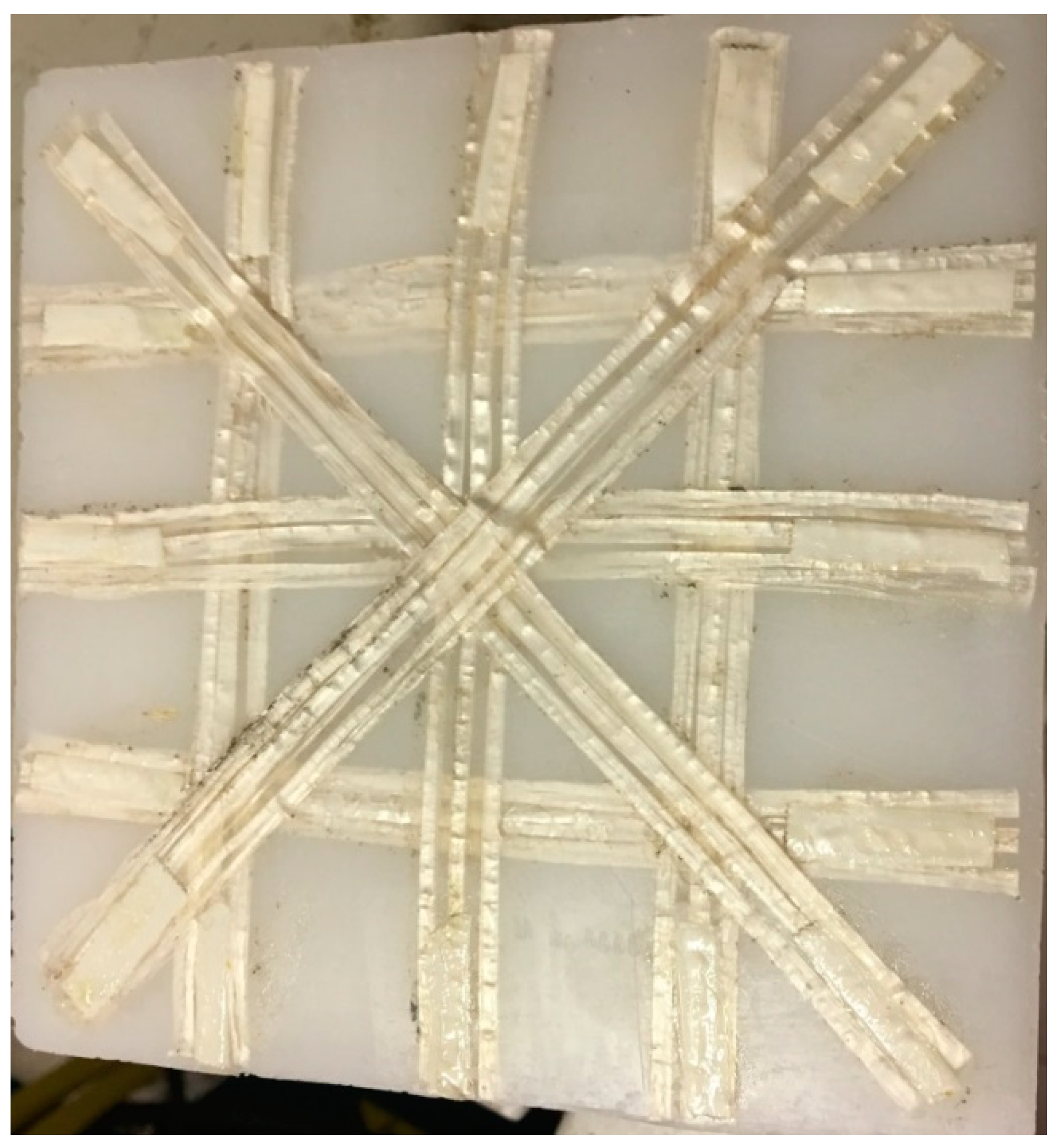
- The first method involved the production of homo-composite bars with 20% wt of UHMWPE and 80% wt of LLDPE through compression molding, using a Campana hot press. A controlled amount of LLDPE and UHWMPE fibers were placed in a 3 mm thick steel frame, after which samples were compression molded at 135 °C, applying a first pressure step of 50 bar for 5 min and a second step of 100 bar for 5 min. Following this, samples were cooled down to room temperature by means of a hydraulic cooling system, under 100 bar pressure. The thickness of compression molded samples was 3 mm. The choice of the temperature during compression molding was based on a preliminary optimization cycle, showing that this is the minimum temperature required to attain good fiber impregnation. The compression molded samples were labeled as HC_CM.
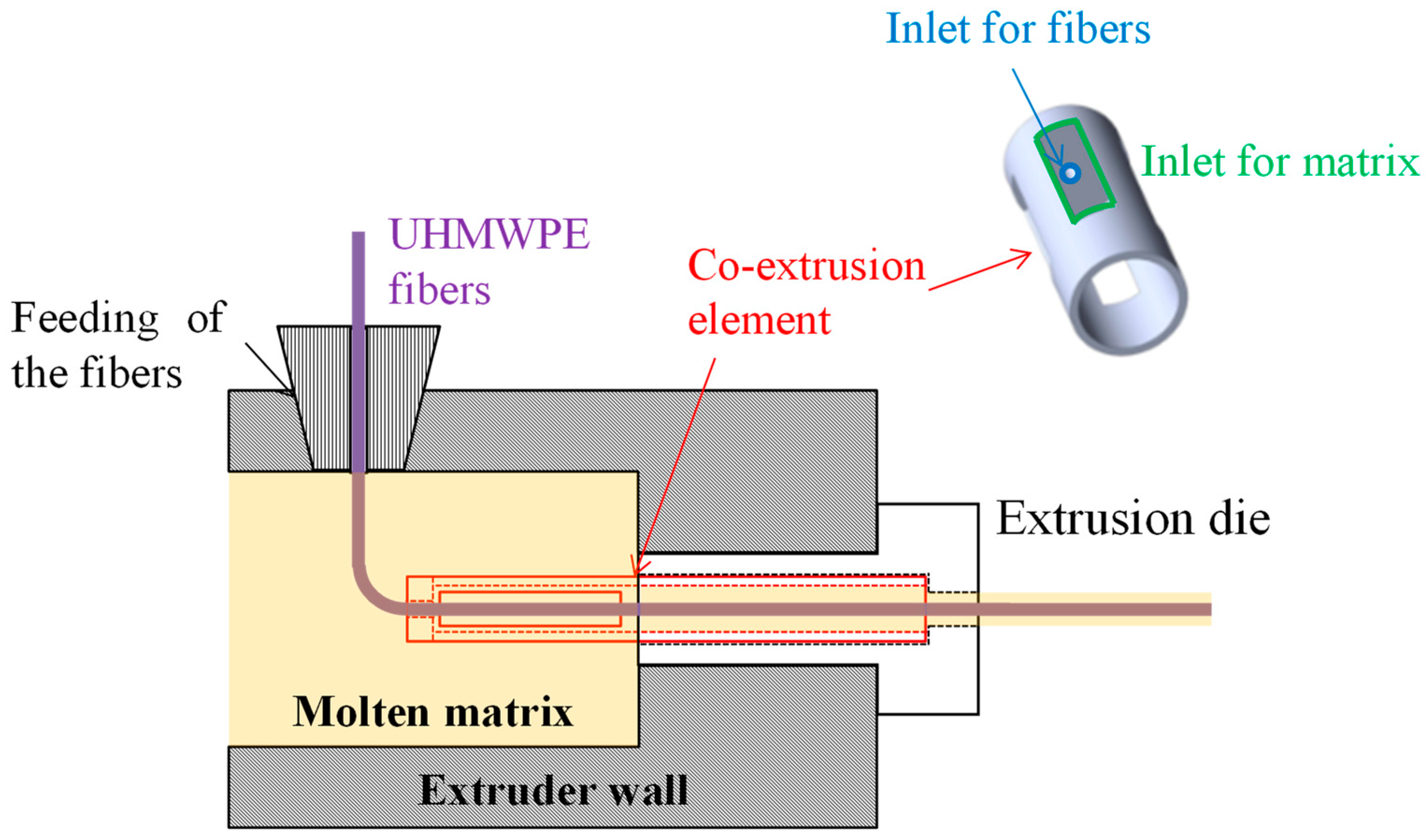
- The second method involved the preliminary production of homo-composites through co-extrusion of LLDPE with UHMWPE fibers. Co-extrusion was performed in a Haake R Rheomex PTW16/25 D twin screw extruder. The extrusion process was run at a screw temperature profile of 140–160–170–160–150–150 °C–130 °C with a screw speed of 7 rpm. The extruder was provided with a 3-mm rod die, modified in order to allow for co-extrusion, as reported in the scheme of Figure 1. Essentially, UHMWPE fibers were fed in the extruder chamber though the pressure gauge gate. A co-extrusion element was placed inside the extrusion die throat, which had a diameter of 6 mm. This co-extrusion element was a cylinder, hollow throughout its length, apart from a solid base. On the solid base, which faces the rear of the extruder, a 2 mm diameter hole allowed for fiber inlet to the die. The hollow cylinder was further provided with holes on its side surface, which allowed for molten matrix inlet to the die. In the hollow length of the co-extrusion element, the molten matrix surrounded the fibers, and the coextruded homo-composite was finally passed though the extrusion die. LLDPE matrix, in powder form, was filled in the extruder and melted before the addition of the fibers, which was attained in the modified die. Therefore, it was expected that the fibers would reach a maximum temperature of 130 °C, the die temperature, during their processing. This procedure allowed for us to obtain a homo-composite with a higher amount of UHMWPE fibers, 30%, and 70% LLDPE matrix. Due to the poor impregnation of the UHMWPE fibers after co-extrusion, further compression molding was carried out with the same processing conditions used for HC_CM. However, in this case, the compression molding temperature was set to 125 °C, and the thickness of reinforcing bars was set to 0.4 mm by the use of a thinner steel frame. Co-extruded samples were labeled as HC_CE, whereas co-extruded and further compression molded samples were labeled as HC_CE_CM.
2.2. Mechanical and Thermal Characterization
3. Results and Discussion
3.1. Thermal Characterization of Polyethylene Homo-Composites
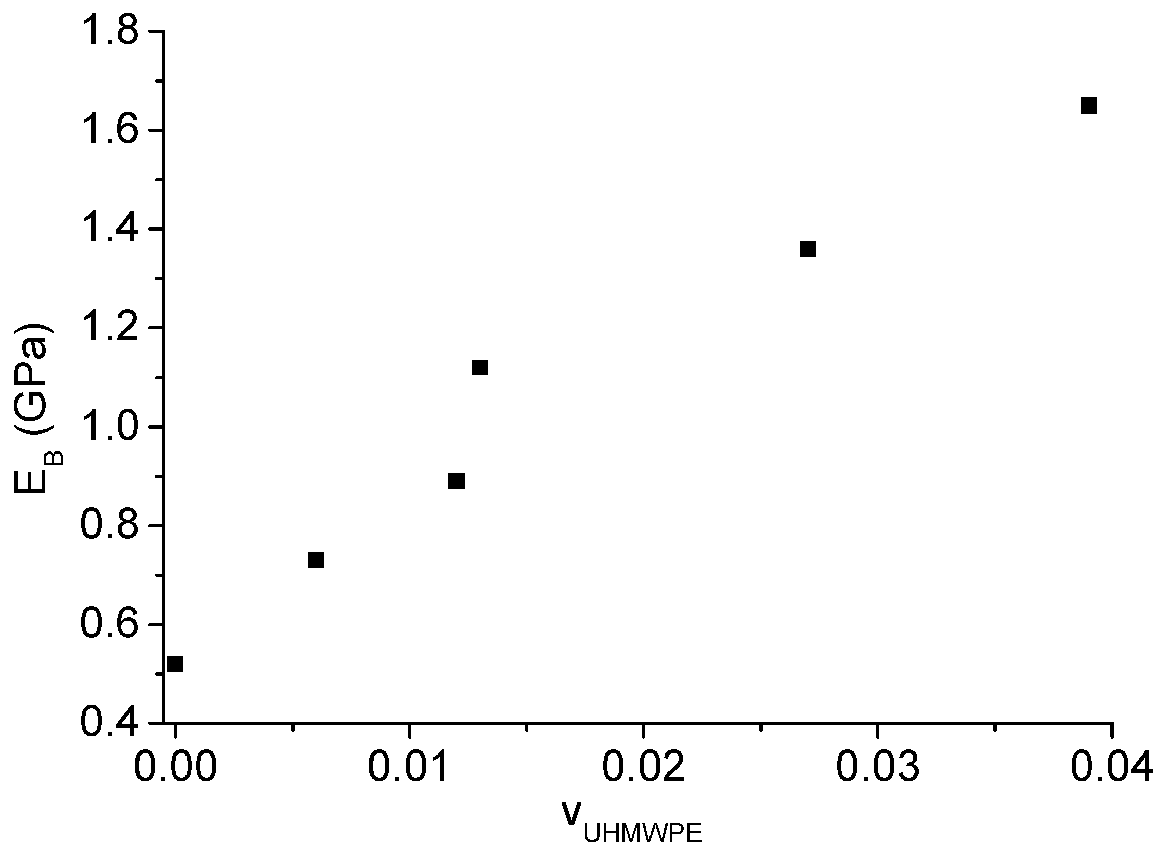
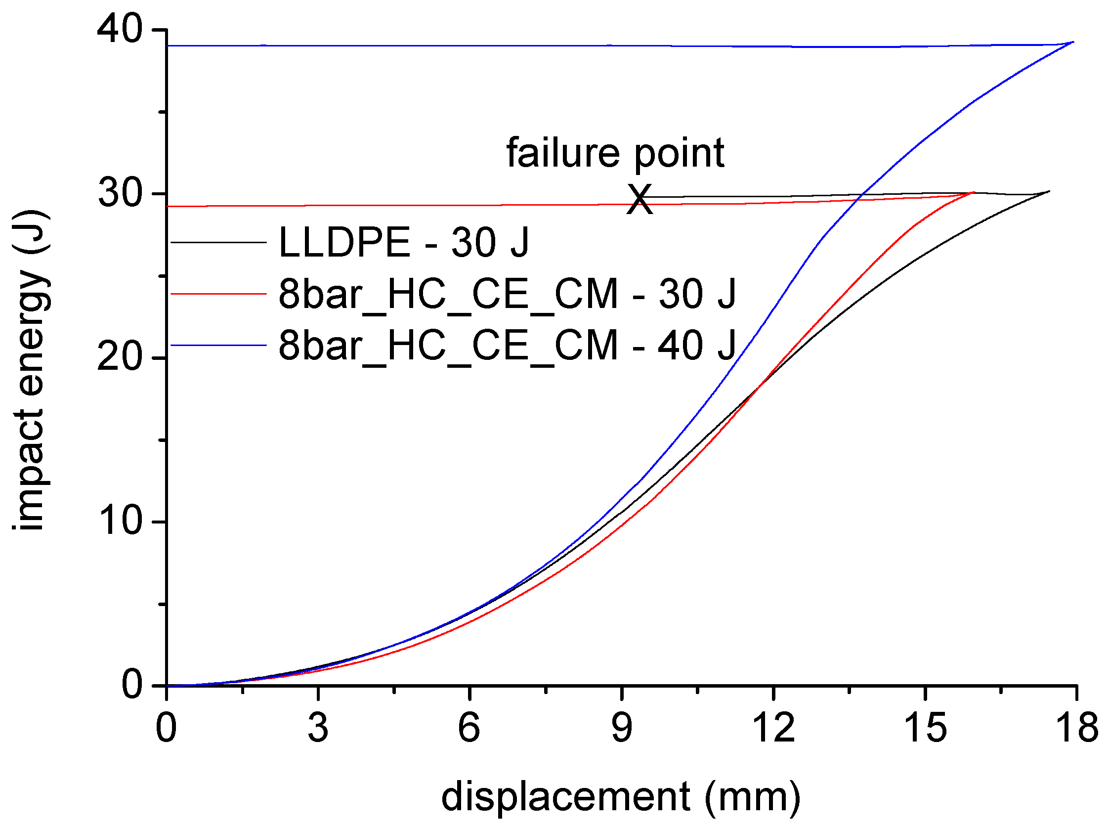
3.2. Mechanical Characterization of Polyethylene Homo-Composites
4. Conclusions
Author Contributions
Funding
Conflicts of Interest
References
- Crawford, R.J. Rotational Moulding of Plastics, 2nd ed.; Research Studies Press: London, UK, 1996. [Google Scholar]
- Planes, E.; Duchet, J.; Maazouz, A.; Gerard, J.F. Characterization of new formulations for the rotational molding based on ethylene–propylene copolymer/graphite nanocomposites. Polym. Eng. Sci. 2008, 48, 723–731. [Google Scholar] [CrossRef]
- Calò, E.; Massaro, C.; Terzi, R.; Cancellara, A.; Pesce, E.; Re, M.; Greco, A.; Maffezzoli, A.; Gonzalez-Chi, P.I.; Salomi, A. Rotational molding of polyamide-6 nanocomposites with improved flame retardancy. Int. Polym. Proc. 2012, 27, 370–377. [Google Scholar] [CrossRef]
- Yan, W.; Lin, R.J.T.; Bhattacharyya, D. Particulate reinforced rotationally moulded polyethylene composites—Mixing methods and mechanical properties. Compos. Sci. Technol. 2006, 66, 2080–2088. [Google Scholar] [CrossRef]
- Yan, W.; Lin, R.J.T.; Bickerton, S.; Bhattacharyya, D. Rotational moulding of particulate reinforced polymeric shell structures. Mater. Sci. Forum. 2003, 437–438, 235–238. [Google Scholar] [CrossRef]
- Blackburn, D.R. An investigation of the production of rotationally moulded composites. In Proceedings of the 9th International Conference on Fibre Reinforced Composites (FRC 2002), University of Newcastle, Newcastle upon Tyne, UK, 26–28 March 2002; pp. 402–407. [Google Scholar]
- Ward, J.; Panigrahi, S.; Tabil, L.G.; Crerar, W.J.; Powell, T. Rotational molding of flax fibre reinforced thermoplastics. In Proceedings of the ASAE Meeting Presentation, Chicago, IL, USA, 2002. Paper No: MBSK 02–209. [Google Scholar]
- Perez, E.; Alvarez, V.; Perez, C.J.; Bernal, C. A comparative study of the effect of different rigid fillers on the fracture and failure behavior of polypropylene based composites. Compos. Part B Eng. 2013, 52, 72–83. [Google Scholar] [CrossRef]
- Greco, A.; Maffezzoli, A. Powder shape analysis and sintering behavior of high density polyethylene powders for rotational molding. J. Appl. Polym. Sci. 2004, 92, 449–460. [Google Scholar] [CrossRef]
- Olinek, J.; Anand, C.; Bellehumeur, C.T. Experimental study on the flow and deposition of powder particles in rotational molding. Polym. Eng. Sci. 2005, 45, 62–73. [Google Scholar] [CrossRef]
- Salomi, A.; Greco, A.; Pacifico, T.; Rametta, R.; Maffezzoli, A. Processing and properties of a polymer/composite double-layer laminate. Adv. Polym. Technol. 2013, 32, E32–E43. [Google Scholar] [CrossRef]
- Salomi, A.; Greco, A.; Felline, F.; Manni, O.; Maffezzoli, A. A preliminary study on bladder-assisted rotomolding of thermoplastic polymer composites. Adv. Polym. Technol. 2007, 26, 21–32. [Google Scholar] [CrossRef]
- Greco, A.; Romano, G.; Maffezzoli, A. Selective reinforcement of LLDPE components produced by rotational molding with thermoplastic matrix pultruded profiles. Compos. Part B Eng. 2014, 56, 157–162. [Google Scholar] [CrossRef]
- Karger-Kocsis, J.; Bárány, T. Single-polymer composites (SPCs): Status and future trends. Compos. Sci. Technol. 2014, 92, 77–94. [Google Scholar] [CrossRef]
- Kmetty, A.; Bárány, T.; Karger-Kocsis, J. Self-reinforced polymeric materials: A review. Progr. Polym. Sci. 2010, 35, 1288–1310. [Google Scholar] [CrossRef]
- Matabola, K.P.; De Vries, A.R.; Moolman, F.S.; Luyt, A.S. Single polymer composites: A review. J. Mater. Sci. 2009, 44, 6213–6222. [Google Scholar] [CrossRef]
- Greco, A.; Maffezzoli, A.; Vlachopoulos, J. Simulation of heat transfer during rotational molding. Adv. Polym. Technol. 2003, 22, 271–279. [Google Scholar] [CrossRef]
- Greco, A.; Maffezzoli, A. Polymer melting and polymer powder sintering by thermal analysis. J. Therm. Anal. Calorim. 2003, 72, 1167–1174. [Google Scholar] [CrossRef]
- Belluzzi, O. Scienza Delle Costruzioni, 3rd ed.; Zanichelli: Bologna, Italy, 1989; Volume 3. (In Italian) [Google Scholar]
- Yeh, J.T.; Lin, S.C.; Tu, C.W.; Hsie, K.H.; Chang, F.C. Investigation of the drawing mechanism of UHMWPE fibers. J. Mater. Sci. 2008, 43, 4892–4990. [Google Scholar] [CrossRef]
- Greco, A.; Maffezzoli, A. Statistical and kinetic approaches for linear low-density polyethylene melting modeling. J. Appl. Polym. Sci. 2003, 89, 289–295. [Google Scholar] [CrossRef]
- Rahmat, A.R.; Maradzi, M.A. Mechanical properties of rotational moulded empty fruit bunch fiber reinforced polyethylene composites. J. Chem. Nat. Resour. Eng. 2008, 2, 41–52. [Google Scholar]
- Lopez-Banuelos, R.H.; Moscoso, F.J.; Ortega-Gudino, P.; Mendizabal, E.; Rodrigue, D.; Gonzalez-Nunez, R. Rotational Molding of Polyethylene Composites Based on Agave Fibers. Polym. Eng. Sci. 2012, 52, 2489–2497. [Google Scholar] [CrossRef]
- Hanana, F.E.; Rodrigue, D. Rotational molding of self-hybrid composites based on linear low-density polyethylene and maple fibers. Polym. Compos. 2018, 39, 4094–4103. [Google Scholar] [CrossRef]
- Höfler, G.; Lin, R.J.T.; Jayaraman, K. Rotational moulding and mechanical characterization of halloysite reinforced polyethylenes. J. Polym. Res. 2018, 25, 132. [Google Scholar] [CrossRef]


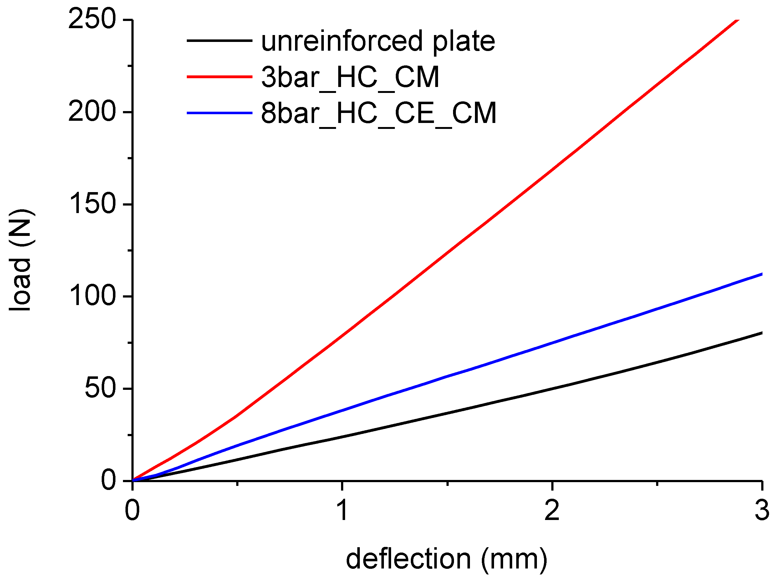
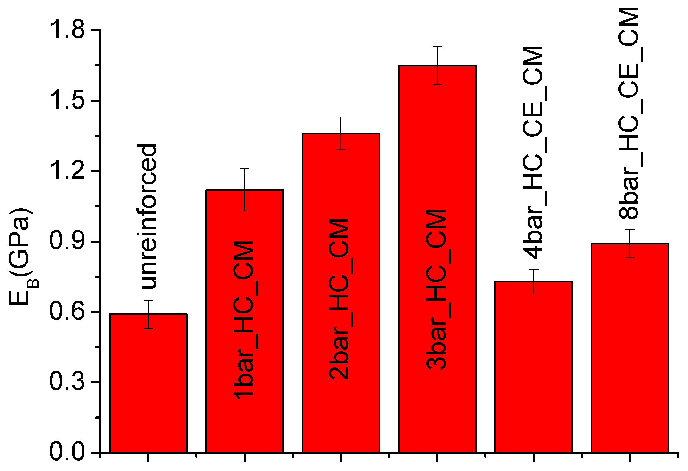
| Sample Code | Reinforcing Homo-Composite | Reinforcement Layout | % of UHWMPE Fibers |
|---|---|---|---|
| 1bar_HC_CM | Compression molded |  | 1.3 |
| 2bar_HC_CM | Compression molded |  | 2.7 |
| 3bar_HC_CM | Compression molded |  | 4 |
| 4bar_HC_CE_CM | Co-extruded and compression molded |  | 0.6% |
| 8bar_HC_CE_CM | Co-extruded and compression molded |  | 1.2% |
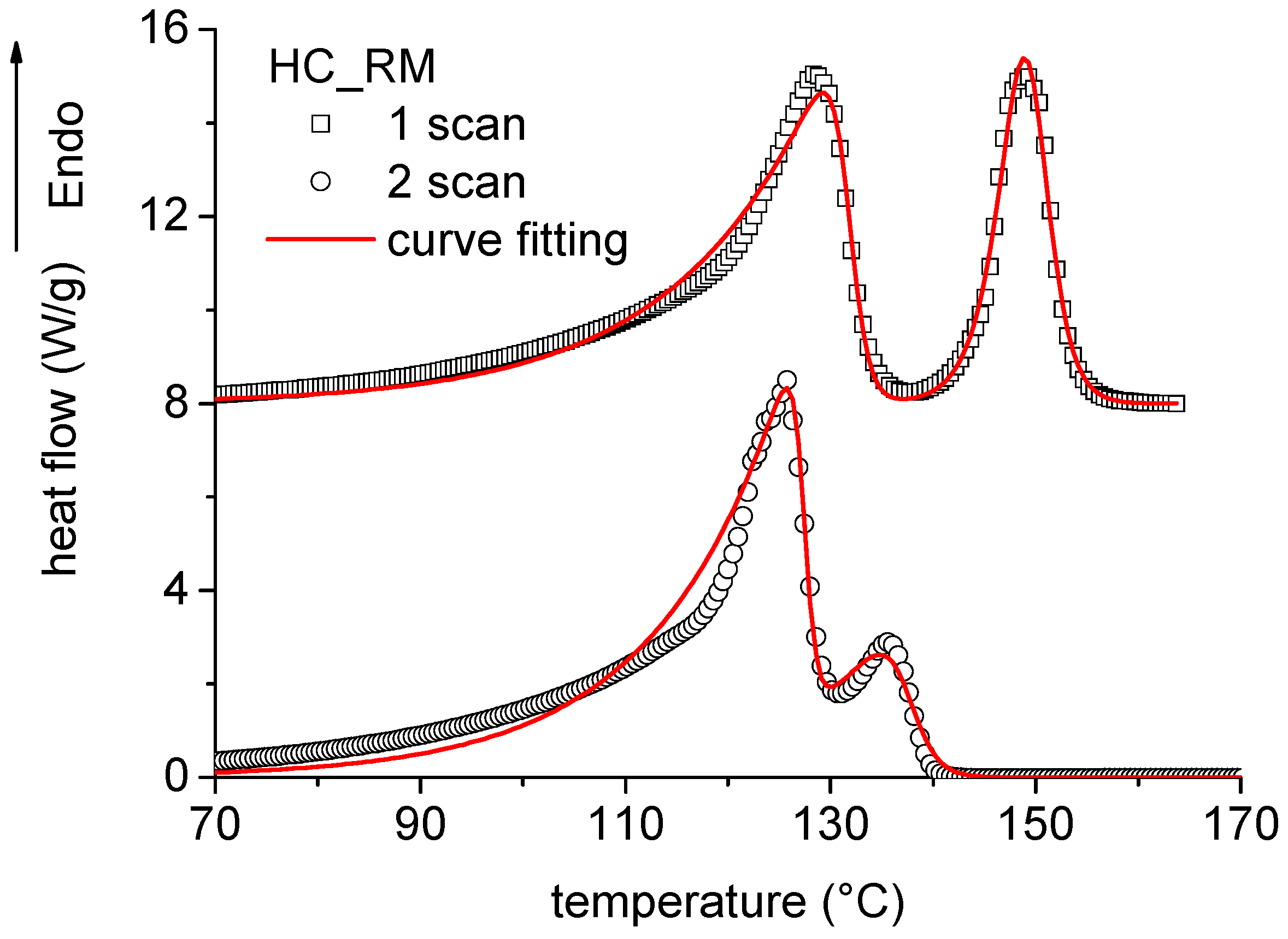
| 2 Scan | dp | Kp (K−1) | Tp (°C) | Equation (4) | Equation (4) (J/g) | |
| Untreated | 158 | 7.8 | 0.737 | 137 | ||
| HC_CM | 36 | 7.8 | 0.737 | 137 | 0.23 | |
| HC_CE | 42.3 | 7.8 | 0.737 | 137 | 0.27 | |
| HC_CE_CM | 50.7 | 7.8 | 0.737 | 137 | 0.32 | |
| HC_RM | 37.9 | 7.8 | 0.737 | 137 | 0.24 | |
| 1 Scan | (J/g) | dp | Kp (K−1) | Tp (°C) | ||
| Untreated | 288 | 1.7 | 0.31 | 152 | ||
| HC_CM | 42 | 2.0 | 0.49 | 148 | 183 | |
| HC_CE | 56.7 | 1.7 | 0.46 | 150 | 212 | |
| HC_CE_CM | 65.3 | 1.4 | 0.44 | 150 | 204 | |
| HC_RM | 48.7 | 2.5 | 0.70 | 149 | 203 |
| Sample | xv | |
|---|---|---|
| HC_CM | 0.93 ± 0.04 | 0.006 |
| HC_CE | 0.82 ± 0.03 | 0.12 |
| HC_CE_CM | 0.92 ± 0.04 | 0.017 |
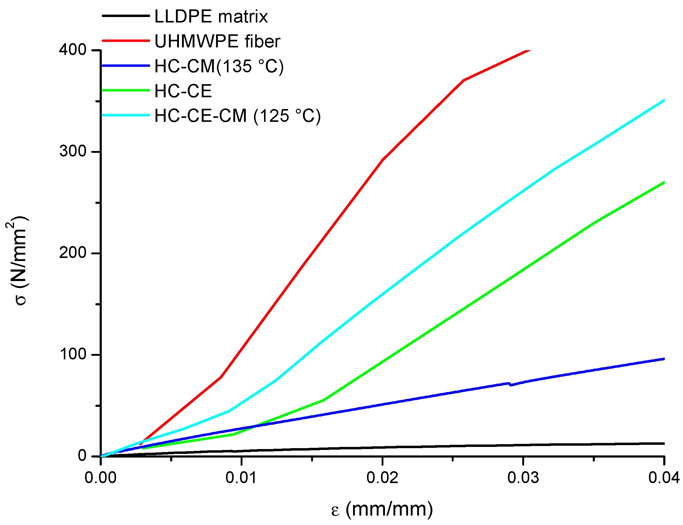
| Sample | E (GPa) | ET (GPa) |
|---|---|---|
| LLDPE matrix | 0.6 | - |
| UHMWPE fibers | 40 | - |
| HC_CM (135 °C) | 2.37 | 8.40 |
| HC_CE | 9.07 | 12.35 |
| HC_CE_CM (125 °C) | 11.10 | 12.35 |
© 2019 by the authors. Licensee MDPI, Basel, Switzerland. This article is an open access article distributed under the terms and conditions of the Creative Commons Attribution (CC BY) license (http://creativecommons.org/licenses/by/4.0/).
Share and Cite
Greco, A.; Ferrari, F.; Buccoliero, M.G.; Trono, G. Thermal and Mechanical Analysis of Polyethylene Homo-Composites Processed by Rotational Molding. Polymers 2019, 11, 528. https://doi.org/10.3390/polym11030528
Greco A, Ferrari F, Buccoliero MG, Trono G. Thermal and Mechanical Analysis of Polyethylene Homo-Composites Processed by Rotational Molding. Polymers. 2019; 11(3):528. https://doi.org/10.3390/polym11030528
Chicago/Turabian StyleGreco, Antonio, Francesca Ferrari, Maria Grazia Buccoliero, and Greta Trono. 2019. "Thermal and Mechanical Analysis of Polyethylene Homo-Composites Processed by Rotational Molding" Polymers 11, no. 3: 528. https://doi.org/10.3390/polym11030528