Article

A Multiband and Multifunctional Metasurface for Linear and Circular Polarization Conversion in Reflection Modes

1
School of Electronics Engineering, Beijing University of Posts and Telecommunications, Beijing 100876, China
2
Department of Telecommunication Engineering, Mehran University of Engineering and Technology, Jamshoro 76062, Pakistan
*
Author to whom correspondence should be addressed.
Crystals 2024, 14(3), 266; https://doi.org/10.3390/cryst14030266
Submission received: 11 February 2024 / Revised: 28 February 2024 / Accepted: 2 March 2024 / Published: 8 March 2024
(This article belongs to the Special Issue Anisotropic Acoustic Metamaterials)

Abstract

:
Multifunctional integrated meta-devices are the demand of modern communication systems and are given a lot of attention nowadays. Most of the research has focused on either cross-polarization conversion (CPC) or linear-to-circular (LP–CP) conversion. However, simultaneously realizing multiple bands with good conversion efficiency remains crucial. This paper proposes a multiband and multifunctional dual reflective polarization converter surface capable of converting a linearly polarized (LP) wave into a circularly polarized (CP) wave, in frequency bands of 12.29–12.63 GHz, 16.08–24.16 GHz, 27.82–32.21 GHz, 33.75–38.74 GHz, and 39.70–39.79 GHz, with 3 dB axial ratio bandwidths of 2.7%, 40.15%, 14.6%, 13.76%, and 0.2%, respectively. Moreover, the converter is capable of achieving CPC with a polarization conversion ratio (PCR) that exceeds 95%, within the frequency ranges of 13.10–14.72 GHz, 25.43–26.00, 32.46–32.56 GHz, and 39.14–39.59 GHz. In addition, to identify the fundamental cause of the CPC and LP–CP conversion, a comprehensive theoretical investigation is provided. Furthermore, the surface current distribution patterns at different frequencies are investigated to analyze the conversion phenomena. A sample prototype consisting of 20 × 20 unit cells was fabricated and measured, verifying our design and the simulated results. The proposed structure has potential applications in satellite communications, radar, stealth technologies, and reflector antennas.

1. Introduction

Electromagnetic (EM) wave manipulation has become essential for many polarization-sensitive applications in the microwave, millimeter wave, and optical fields, including in regard to absorbers, lenses, cloaking devices, and polarization converters [1,2,3,4,5]. In general, there are two types of polarization conversion mechanism. The birefringence effect, in naturally available crystals, divides the electric field vector into two orthogonal components [6]. Another way to obtain polarization conversion is molecular chirality (optical activity) [7]. These devices are not very useful in sub-miniaturized applications due to their bulky volume, limited bandwidth, high loss, and incident angle-dependent response. Metasurfaces are specifically engineered configurations, normally with a low profile, which are made up of lightweight materials that can overcome traditional methods. Metasurfaces are known for their capacity to alter polarization over various frequency ranges, such as visible [8,9,10,11], terahertz [12], infrared [13], and microwave [14] frequencies. Recent years have seen the emergence of different metasurface-based polarization converter types that can convert various electromagnetic wave polarization states, such as cross-polarization conversion [15,16], linear polarization conversion (LP) to circular polarization (CP) conversion [17,18,19,20,21,22], and right- to left-handed CP conversion [23,24]. The main issue with a metasurface in the electromagnetic field remains the same, i.e., maximum polarization converters still only operate a single function, and multiband polarization converters have relatively narrow bandwidths [25,26]. Recently, some all-metal phase-shifting structures have been proposed; these structures are either single-frequency or polarization-dependent structures. Some structures can only support waves that are either linearly or circularly polarized, due to a very limited bandwidth. However, because of the limitations of a substrate-less design, it is more difficult to simultaneously offer a set of desirable characteristics via an all-metal structure. An all-metal wideband phase-correcting structure (AWPCS), without these limitations, is generated based on the relative phase error obtained from post-processing actual near-field distributions of any EM sources [27]. However, researchers are trying to design broadband and single-layer cross-polarizers. In [28], the authors present a lightweight reflective polarizer constructed in an oval-shaped design that enables wideband CPC in the 10.2–20.5 GHz frequency range. Several effective and wideband cross-converters using a single layer have been described, including a slotted semicircle [29], a square-split-ring metasurface [30], a W-shaped metasurface [31], and a T-shaped metasurface [32]. Nevertheless, these structures only support CPC as a single operation.
In addition, many researchers have focused on different metasurfaces to integrate many functionalities into a single structure. A polygon-shaped linear-to-circular (LP–CP) converter, with a 46% axial ratio (AR) bandwidth from 7.62 to 12.16 GHz, was recently proposed by Kundu et al., using anisotropic impedance surfaces in reflection mode [33]. This converter is capable of achieving both left- and right-handed circular polarization. A reflection-based single-layered multiband polarization converter in the K and Ka bands was proposed by Coskun et al. [34]. The structure was based on a hexagonal-shaped metal patch enclosed in a hexagonal ring, with a diagonal split only in the ring. It acts as a linear-to-circular polarization converter in dual bands, from 16.23 to 16.75 GHz and 48.6 to 48.8 GHz. The study in [35] describes a reflective multiband converter achieving maximum CPC at 13, 16, and 18 GHz. In [36], a novel polarization-twisting antenna configuration is presented that uses a linear polarization conversion metasurface to transform the radiated LP wave into an x-polarized wave. In low- and high-frequency bands, the dual linear-to-circular polarization converter can change the x-polarization wave into a left-handed circularly polarized (LHCP) wave and a right-handed circularly polarized (RHCP) wave. The limitations are that the composite structure is quite complex, large in size, and has a narrow bandwidth. A low-profile, multifunctional metasurface converter that is small in size and has both CPC and LP–CP functions is described in [37]. However, the additional air layer and the consequences of angular tolerance are not addressed. Because the designs mentioned above are unable to meet the conditions of multifunctionality and integration needed for the large-scale communication systems in use today [38], the application of polarization converters is severely limited. Today, the focus of researchers is on creating polarization converters that have multiple functions, are small in size, and have a larger bandwidth.
In light of the above limitations of polarization converters, a new single-layer reflective multiband polarization converter for LP–CP and CPC is proposed in this paper. LP–CP conversion is realized across five distinct frequency bands, with incident vertical polarization by the metasurface converter. On the other hand, CPC is achieved across four frequency bands. To better comprehend the physical insights on the reflective metasurface and to investigate its performance, analysis of the surface current distributions has been carried out. Despite its simplicity, our design has potential applications in polarization manipulation, including antenna design and wireless communications.

2. Unit Cell Design

Figure 1 depicts the complete structure of the unit cell and evaluation process. The proposed unit cell for the polarization converter is composed of a PTFE substrate, with a thickness of h = 1.6 mm, ϵ r = 2.1 , and tan   δ ( t a n g e n t   l o s s ) = 0.0002 . The top pattern and metallic ground plane are composed of copper, which has a thickness of 35 µm and an electric conductivity of 5.8 × 10 7   S/m.
Figure 1 depicts the two evaluation processes for the meta-atom. In the evolution stage of the meta-atom, the semicircle patch structure (type I) is depicted in Figure 1a. In step 2, the slotted rectangular patch (type II) is shown in Figure 1b. Finally, the proposed meta-atom is constituted by combining a slotted rectangular patch with a semicircle, as shown in Figure 1c. The schematic figure of the proposed meta-atom is illustrated in Figure 1d. The equivalent LC circuit of the slotted rectangular patch combined with a semicircle is shown in Figure 2. The red dotted box shows the equivalent circuit of the slotted rectangular patch and the blue dotted box indicates the equivalent circuit of the semicircle. The optimized dimensions of the proposed meta-atom are tabulated in Table 1.

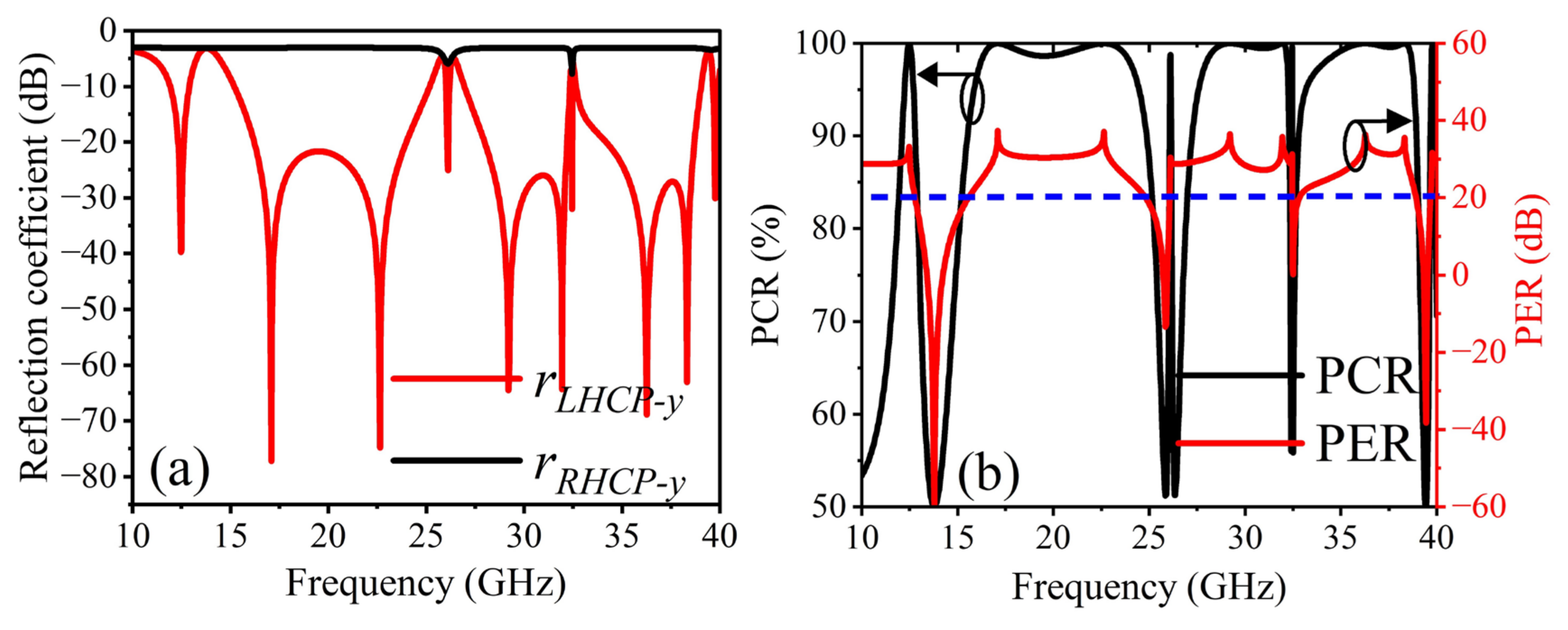
3. Simulated Results and Discussion

The proposed meta-atom was designed and simulated using CST Microwave Studio 2021, in the reflection mode. The boundary conditions were defined as a unit cell on the x- and y-planes, and a Floquet port was used for excitation in the z-direction. We used the x- and y-polarized wave as the incident wave and defined the co- and cross-polarization reflection coefficients as follows:
r x x = E x r E x i   and   r y y = E y r E y i
r y x = E y r E x i   and   r x y = E x r E y i
An electric field is denoted by E . Moreover, ‘ i ’ and ‘ r ’ denote the incident and reflected EM wave, respectively. The polarization conversion ratio (PCR) can be employed to evaluate the CPC performance of a meta-atom. The PCR for an incident wave with linear polarization can be calculated using the following formulas [37]:
P C R x = r y x 2 r y x 2 + r x x 2   and   P C R y = r x y 2 r x y 2 + r y y 2
where the reflection coefficients for cross-polarization are r x y and r y x . The co-polarization reflection coefficients are expressed by r y y and r x x , respectively. In Equation (3), P C R x and P C R y represent the polarization conversions for x- and y-polarized incidence waves, respectively. The simulated results under normal x- and y-polarized incidence waves are illustrated in Figure 3. In the unit cell’s evolution stages, the semicircle patch structure, depicted in Figure 3a, performs as an LP–LP converter at 39.74 GHz, with a magnitude value of 1.0 for r x y and r y x , respectively. In general, an amplitude of more than 80% or a magnitude of less than −10 dB ( r y y or r x x < 10 dB) is deemed effective for co-polarization. Furthermore, an efficient performance requirement for the cross-polarization reflection coefficient is 0 dB < r y x < 3 dB or 0 dB < r x y < 3 dB. As depicted in Figure 3b, in single-frequency bands, covering from 17.77 to 26.01 GHz, the cross-polarization coefficient ( r y x ) has a magnitude that is expressively greater than the co-polarization coefficient ( r x x ). Finally, the slotted rectangular patch was added with a semicircle to enhance the polarization conversion mechanism. By integrating a slotted rectangular patch with a semicircle, the improvement in the r x y and r y x values can be tailored for particular frequency bands. As shown in Figure 3c, the resulting r x y and r y x values at the frequencies 13.81 GHz, 25.75 GHz, and 39.65 GHz, are about one, demonstrating effective CPC. Hence, in the subsequent Equation (3), the PCR values achieve 100% at 13.10–14.72, 25.43–26.00, 32.46–32.56, and 39.14–39.59 GHz, as indicated in Figure 3d. The simulated result verifies the efficiency of the proposed structure as an LP converter in the above frequency ranges. In addition, the proposed structure also performs another important function known as LP–CP conversion, or the quarter-wave plate operation (QWP). In reflection mode, two main conditions must be satisfied to accomplish LP–CP conversion. The amplitude of the reflected co- and cross-polarization components must be nearly equal r x y = r y y and r y x = r x x , and the phase difference Δ φ y x between the co- and cross-polarization components should be ± 90 ° , or an odd multiple of 90 ° . Figure 3c shows that the co- and cross-polarization reflection coefficients of the proposed structure, which has an LP–CP function, have a comparable amplitude in five frequency bands: 12.29–12.63, 16.08–24.16, 27.82–32.21, 33.75–38.74, and 39.70–39.79 GHz. Furthermore, Figure 4a shows the phase difference between the five frequency bands as mentioned above, which is nearly equal to ± 90 ° or an odd multiple of 90°. Thus, both conditions for the LP–CP conversion have been satisfied in the frequency ranges 12.29–12.63, 16.08–24.16, 27.82–32.21, 33.75–38.74, and 39.70–39.79 GHz. In addition, we express the AR to calculate the CP waves. In the design, an AR of less than 3 dB is generally considered a CP wave, and the AR can be determined using the following equation [9]:
A R = 10 log 10 tan χ
where ‘ χ ’ denotes the elliptical angle, and follows this equation:
χ = 1 2 arcsin β
where ‘ β ’ is ellipticity and can be calculated as:
β = 2 R sin Δ φ 1 + R 2   and   R = r x y r y y
where Δ φ = φ y y φ x y denotes the phase difference of the reflection coefficients. Where the corresponding co- and cross-polarization phases are φ y y and φ x y , respectively. According to EM wave theory, the reflected wave is RHCP if χ = 45 ° Δ φ = 90 ° and LHCP if χ = 45 ° Δ φ = 90 ° . Also, the reflected wave is LHCP if β = + 1 and RHCP if β = 1 , respectively. Figure 4b, c show the AR and elliptical angle with the ellipticity curves of the proposed structure. The AR is less than 3 dB in the five frequency bands of 12.29–12.63, 16.08–24.16, 27.82–32.21, 33.75–38.74, and 39.70–39.79 GHz; therefore, the LP incident waves in these bands will be reflected as CP waves. The blue dotted line indicates the 3 dB region.
Figure 4c shows that the ellipticity is almost ± 1 within the five frequency bands of 12.46, 16.78–23.14, 28.84–32.02, 35.04–38.46, and 39.76 GHz, respectively. Three frequency bands have RHCP waves, namely 16.78–23.14, 28.84–32.02, and 35.04–38.46 GHz; the two frequency bands that have LHCP waves are 12.46 and 39.76 GHz.
Additionally, Figure 4c demonstrates that the elliptical angle is approximately 45 ° in three frequency ranges, namely 16.78–23.14, 28.84–32.02, and 35.04–38.46 GHz, and the elliptical angle is close to + 45 ° in two frequency ranges, 12.46 and 39.76 GHz, demonstrating that the reflected polarized waves are RHCP and LHCP, respectively. Figure 4d shows that the reflection components r y y and r x y have nearly the same magnitude r x y / r y y 1 for the frequencies 12.46, 16.88–23.11, 26.1–32.44, 34.97–38.49, and 39.75 GHz, where yellow area represents that the ratio of co-and cross-polarization are nearly equal to 1. There are several bands between 10 and 40 GHz where circular polarization is satisfied. It is worth mentioning that the five frequency bands offer near-ideal CP conversion. These ideal characteristics are attributed to the negligible loss in the substrate, equal power distribution, and ± 90 ° (or an odd integral multiple of 90 ° ) phase difference between the two orthogonal reflection components. Now, we express two LP–CP reflection coefficients ( r R H C P y and r L H C P y ) , PCR and PER [17], as the following equations:
r R H C P y = 2 2 r x y + i r y y   and   r L H C P y = 2 2 r x y i r y y
P C R = r R H C P y 2 r R H C P y 2 + r L H C P y 2   and   P E R = 20 log r R H C P y r L H C P y
Figure 5a illustrates the calculated reflection coefficients for the left-and right-handed circularly polarized ( r L H C P y and r R H C P y ) waves in dB. The magnitude of r R H C P y in the frequency range 10–40 GHz is below −3 dB (approximately equal to 0 dB), and r L H C P y in the multiband is below −20 dB, respectively. It indicates that the reflected wave at the y-polarized incidence wave has entirely converted into multiple bands. The additional components of the polarization reflection coefficient include the polarization conversion ratio (PCR) and the polarization extinction ratio (PER). The PER is an approach that shows potential for evaluating LP–CP conversion. The proposed metasurface performs perfect LP–CP conversion at five frequencies, namely 12.46, 16.88–23.11, 26.1–32.44, 34.97–38.49, and 39.75 GHz, respectively. The acquired PCR, shown in Figure 5b, also demonstrates that the PCR can be sustained at greater than 95.0% in the abovementioned frequency bands, covering the 3 dB AR band, indicating that the proposed converter has significantly greater efficiency. The polarization conversion performance of an LP–CP converter is also expressed through the PER, which defines the ratio of a wave’s RHCP component to its LHCP component. Figure 5 illustrates that RHCP is obtained over three frequency bands, 16.88–23.11, 26.1–32.44, and 34.97–38.49 GHz, since the PER magnitude is greater than +20 dB. Moreover, the LHCP mode is achieved by covering two frequencies, 12.46 and 39.76 GHz, because the PER value is smaller than −20 dB, as illustrated in Figure 5b. So, the highly efficient metasurface converts the incident LP wave into a CP wave at different frequencies.

4. Parametric Analysis

In this section, some efficient parameters have been analyzed to carry out a parametric investigation. Optimized parameters are used to verify the polarization conversion ratio and 3 dB linear-to-circular polarization bandwidth. To attain the optimal parameters, we varied the values of the substrate thickness (h), angle of incidence ( θ in degree), and material properties ε r . The influence of the parameters on the phase difference and 3 dB AR of the proposed metasurface unit cell was evaluated using some parameter simulations, as only one of the components varies, while the other remains constant.
Figure 6 illustrates the calculated 3 dB AR and phase difference of the proposed metasurface. The 3 dB AR is influenced by varying the parametric values of the substrate thickness (h = 1.55, 1.60 and 1.65 mm), the angle of the incident wave ( θ = 0 ° to 30 ° ) , and material properties ( ε r = 2.0, 2.1 and 2.2), as illustrated in Figure 6a–c. However, increasing the substrate thickness (from 1.55, 1.60, and 1.65 mm) will modify the bandwidth of a metasurface, so 1.60 mm is preferred as the optimal size to achieve high polarization conversion efficiency in multiband frequency, as illustrated in Figure 6a. In the meantime, the AR performance is roughly influenced by varying the angle of the incident wave from its optimal value, as shown in Figure 6b. It can be seen that at multiple frequency bands, the AR values are stable up to 20 ° . One more important parameter of the proposed metasurface is the material properties. Figure 6c illustrates the response from varying the ‘ ε r ’. The material properties had no significant effect on the CP conversion, however, and had a slight impact on the overall bandwidth of the frequency bands, as depicted in Figure 6c. By varying the substrate thickness, Figure 6d demonstrates that the phase difference is almost ± 90 ° or an odd integral multiple of ± 90 ° . From Figure 6d, it is clear the phase difference remains the same when varying the substrate thickness.

5. Theoretical Analysis

To evaluate the polarization conversion mechanism of the proposed structure the u - and v -axes are initiated, as illustrated in Figure 7. The proposed structure is explained by reinterpreting the x o y as the u o v coordinate system, by rotation 45 ° anticlockwise. As illustrated in Figure 7, the u - and v -axes are ± 45 ° with respect to the y -axis, respectively, and the y -polarized incident wave can be decomposed into u and v components:
E i = y ^ E i y e j k z = u ^ E u i + v ^ E v i e j k z = 2 / 2 E y i u ^ + v ^ e j k z
So, the equation for the reflected waves is as follows:
E r = u ^ E u r + v ^ E v r e j k z = u ^ r u E u i + v ^ r v E v i e j k z = 2 / 2 E y i u ^ r u e j φ u + v ^ r v e j φ v e j k z
where r u and r v stand for the reflection coefficients of the co-polarized wave for the u - and v -polarized incidence waves, and the corresponding reflection phases of the reflected waves are indicated by φ u and φ v . The phase difference between them is the main factor in the polarization conversion. The metasurface symmetry along the u - and v -axes results in extremely low cross-polarization and significant co-polarization reflection. The phase difference is typically described as Δ φ u v = φ u φ v . Reflected electromagnetic waves of various polarization types can be obtained when the phase and magnitude of the reflected wave along the u - and v -axes satisfy the requirements.
The following equation represents condition 1:
r u r v   and   Δ φ u v = 180 ° ± n π
where n is a constant, and the reflected wave is an LP wave. The following equation expresses condition 2:
r u r v   and   Δ φ u v = ± 90 ° ± 2 n π
where Equation (12) represents a CP reflected wave. Figure 8a,b display the amplitude of the reflection coefficients, and the reflection phase curves of the proposed metasurface for the u - and v -polarized incidence waves, whereas Figure 8c shows the phase difference curve. In the distinct frequency ranges of 10.09–11.83, 16.34–23.90, 28.87–31.72, and 33.68–38.69 GHz, as anticipated, r u r v , and the phase difference is approximately ± 180 ° . It satisfies the above-analyzed Equation (11) and accomplishes the conversion of the y -polarized wave into the x -polarized wave, or CPC. The conversion from an LP wave to a CP wave is achieved in the distinct frequency ranges of 10.01–11.59, 15.33–25.15, 27.18–32.15, and 33.03–38.56 GHz; where r u r v , the phase difference is approximately an odd integral multiple of 90°, as shown in Figure 8c. Finally, the AR of the reflected wave is calculated from the above data following the phase difference Δ φ u v obtained in Figure 8c, and the resulting findings are displayed in Figure 8d. The derived AR essentially agrees with one of the phase differences Δ φ y x , as shown in Figure 8d. By using the surface current distribution, the conversion mechanism is evaluated. Figure 9 displays the surface current distribution on the top and bottom layers in response to u and v components at resonance frequencies of 13.59, 26.16, 32.59, and 39.70 GHz. These can be magnetic resonances or electric resonances from the proposed converter. Furthermore, magnetic resonance happens when a current flows in the opposite direction through the bottom and top metallic plates. Figure 9b–d demonstrates that the surface currents at the top of the layer are anti-parallel to the surface currents at the bottom, at the three resonance frequencies 26.16, 32.59, and 39.70 GHz. The surface current density at the top and bottom are parallel at 13.59 GHz. This indicates an electric resonance at 13.59 GHz, as seen in Figure 9a. Table 2 provides a detailed evaluation of the proposed design in comparison to recently reported single-layer converters.

6. Experimental Results

We fabricated the metasurface and measured it to verify the simulated results. Figure 10a illustrates the fabrication of 20 × 20 elements totaling 120 × 120 mm2 to practically verify the attributes of the proposed metasurface. Metallic copper designs are etched onto the thin layer of PTFE ( ϵ r = 2.1 ), using printing circuit technology. The metal layer has a thickness of 0.035 mm, whereas the PTFE layer has a thickness of 1.6 mm. A metallic copper plate is used on the back side of the substrate to achieve complete reflection. As shown in Figure 10b, the experiments are performed in an anechoic chamber to eliminate reflections and background noise, for accurate results. With the aid of two different sets of LP horn antennas, the reflected waves in two frequency sweeps (8–18 GHz and 18–40 GHz) are measured. These horn antennas are associated with the Agilent vector network analyzer N5230.
To collect the reflected waves from the metasurface, wideband two-horn antennas are employed. To calculate the LP–CP conversion, both the co- and cross-polarized reflection coefficients need to be measured. In order to measure the reflected co-polarized components, both antennas are oriented horizontally (vertically) in the same direction. On the other hand, the receiving antenna is placed horizontally, while the transmitting antenna is positioned vertically, in order to measure the cross-polarized reflection coefficients. Figure 11a displays the simulated and measured results of the co- and cross-polarization conversion. Also, the PCR is measured and depicted in Figure 11b for LP–LP verification. We also measured the LP–CP performance of the proposed structure. Figure 11c shows the measured AR of the proposed metasurface. With slight discrepancies caused by fabrication tolerances, the agreement between the simulation and measurement is considered satisfactory. Notably, the measured resonant frequencies correspond with the values predicted by the simulations for a typically incident y -polarized wave. Performance comparisons between the newly developed LP–CP and reflective CPC metasurface and previously published studies, in multiple frequency bands, are shown in Table 2. Thus, the anticipated LP–CP conversion and CPC are realized in multiple frequency bands, between 10 GHz and 40 GHz. As discussed above, the angular stability of the design is analyzed over a wide range of incident angles. The results of the AR are shown in Figure 6b, with θ varying from 0° to 30°. Figure 6b demonstrates the effect of oblique incidence on the dip in 3 dB resonance. The third resonance 3 dB dip is sensitive to the incident angle, with the bandwidth shrinking at a higher frequency. It can be reasonably concluded from the 3 dB dip resonances that the designed metasurface is angularly stable over a wide range of incident angles, making it suitable for various applications.

7. Conclusions

In summary, a single-layer, multiband and multifunctional polarization converter was designed in this paper. The design principle of the proposed polarizer, which is based on a simple semicircle embedded with a rectangular slot, was thoroughly investigated, and evaluated. The proposed polarization converter achieves LP–CP conversion at five frequency bands and CPC at four frequency bands, with high efficiency. The physical process of polarization conversion is proposed, while considering the surface current distribution. Experimental measurements were carried out to verify and show good agreement with the simulation results. Moreover, a comprehensive comparison of the proposed structure with recently published single-layer polarization converters highlighted its advantages.

Author Contributions

Conceptualization, J.Y.; Methodology, S.H.; Software, S.H.; Validation, W.Y.; Formal analysis, F.A.U.; Investigation, M.I.; Resources, J.Y.; Data Curation, J.Y.; Writing—original draft, S.H.; Writing—review and editing, S.H.; Visualization, J.Y.; All authors have read and agreed to the published version of the manuscript.

Funding

This work was supported by National Natural Science Foundations of China (No. 62127802).

Data Availability Statement

The original contributions presented in this study are included in the article, further inquiries can be directed to the corresponding author/s.

Conflicts of Interest

The authors declare no conflicts of interest.

References

  1. Fahad, A.K.; Ruan, C.; Nazir, R.; Hassan, B. Transmissive Polarizer Metasurfaces: From Microwave to Optical Regimes. Nanomaterials 2022, 12, 1705. [Google Scholar] [CrossRef]
  2. Ding, F.; Tang, S.W.; Bozhevolnyi, S.I. Recent advances in polarization-encoded optical metasurface. Adv. Photon. Res. 2021, 2, 2000173. [Google Scholar] [CrossRef]
  3. Faniayeu, I.; Asadchy, V.; Fanyaev, I. Polarization Control with Helical Metasurfaces. Crystals 2020, 10, 726. [Google Scholar] [CrossRef]
  4. Badri, S.H.; Gilarlue, M.M.; Saeid, N.S.; Kim, J.S. Narrowband-to-broadband switchable and polarization-insensitive terahertz metasurface absorber enabled by phase-change material. J. Opt. 2022, 24, 025101. [Google Scholar] [CrossRef]
  5. Maral, G.; Bousquet, M.; Sun, Z. Satellite Communications Systems: Systems, Techniques, and Technology; John Wiley & Sons: Hoboken, NJ, USA, 2020. [Google Scholar]
  6. Nilotpal Nama, L.; Bhattacharyya, S.; Chakrabarti, P. A metasurface-based broadband quasi nondispersive cross polarization converter for far infrared region. Int. J. RF Microw. Comp. Aided. Eng. 2019, 29, e21889. [Google Scholar] [CrossRef]
  7. Jeyaraj, J.P.G.; Swaminathan, A. An efficient reflective polarization rotation meta surface for broadband RCS reduction. Int. J. RF Microw. Comp. Aided. Eng. 2018, 28, e21474. [Google Scholar] [CrossRef]
  8. Cheng, Z.; Cheng, Y. A multi-functional polarization convertor based on chiral metamaterial for terahertz waves. Opt. Commun. 2019, 435, 178–182. [Google Scholar] [CrossRef]
  9. Majeed, A.; Zhang, J.; Ashraf, M.A.; Memon, S.; Mohammadani, K.H.; Ishfaq, M.; Sun, M. An ultra-wideband linear-to-circular polarization converter based on a circular, pie-shaped reflective metasurface. Electronics 2022, 11, 1681. [Google Scholar] [CrossRef]
  10. Chen, L.; Ma, Q.; Luo, S.S.; Ye, F.J.; Cui, H.Y.; Cui, T.J. Touch-Programmable Metasurface for Various Electromagnetic Manipulations and Encryptions. Small 2022, 18, 2203871. [Google Scholar] [CrossRef]
  11. Ma, Q.; Gao, W.; Xiao, Q.; Ding, L.; Gao, T.; Zhou, Y.; Gao, X.; Yan, T.; Liu, C.; Gu, Z.; et al. Directly wireless communication of human minds via non-invasive brain-computer-metasurface platform. eLight 2022, 2, 11. [Google Scholar] [CrossRef]
  12. Bilal, R.M.H.; Baqir, M.A.; Choudhury, P.K.; Ali, M.M.; Rahim, A.A. On the specially designed fractal metasurface-based dual-polarization converter in the THz regime. Results Phys. 2020, 19, 103358. [Google Scholar] [CrossRef]
  13. Wen, D.; Yue, F.; Li, G.; Zheng, G.; Chan, K.; Chen, S.; Chen, M.; Li, K.F.; Wong, P.W.H.; Cheah, K.W.; et al. Helicity multiplexed broadband metasurface holograms. Nat. Commun. 2015, 6, 8241. [Google Scholar] [CrossRef] [PubMed]
  14. Majeed, A.; Zhang, J. A study of linear-to-linear (LTL) cross-polarization conversion metasurface (CPCM) in microwave regime. Optik 2023, 274, 170497. [Google Scholar] [CrossRef]
  15. Long, F.; Yu, S.; Kou, N.; Zhang, C.; Ding, Z.; Zhang, Z. Efficient broadband linear polarization conversion metasurface based on %-shape. Microw. Opt. Technol. Lett. 2020, 62, 226–232. [Google Scholar] [CrossRef]
  16. Das, P.; Mandal, K. Polarization converter surface integrated MIMO antenna for simultaneous reduction of RCS and mutual coupling. IEEE Antennas Wirel. Propag. Lett. 2022, 21, 1782–1786. [Google Scholar] [CrossRef]
  17. Majeed, A.; Zhang, J.; Awan, Z.A.; Memon, S.; Ishfaq, M.; Wang, C. A high-efficiency dual-band linear-to-circular polarization converter based on rectangular-slot reflective metasurface. Appl. Sci. 2022, 12, 9172. [Google Scholar] [CrossRef]
  18. Lin, B.Q.; Huang, W.Z.; Lv, L.T.; Guo, J.X.; Huang, S.Q.; Zhu, R. An ultra-wideband linear-to-circular polarization conversion realized by an 8-shaped metasurface. Plasmonics 2021, 62, 629–634. [Google Scholar] [CrossRef]
  19. Khan, M.I.; Chen, Y.; Hu, B.; Ullah, N.; Bukhari, S.H.R.; Iqbal, S. Multiband linear and circular polarization rotating metasurface based on multiple plasmonic resonances for C, X and K band applications. Sci. Rep. 2020, 10, 17981. [Google Scholar] [CrossRef]
  20. Lin, B.; Lv, L.; Guo, J.; Liu, Z.; Ji, X.; Wu, J. An ultra-wideband reflective linear-to-circular polarization converter based on anisotropic Metasurface. IEEE Access 2020, 8, 82732–82740. [Google Scholar] [CrossRef]
  21. Markovich, D.L.; Andryieuski, A.; Zalkovskij, M.; Malureanu, R.; Lavrinenko, A.V. Metamaterial polarization converter analysis: Limits of performance. Appl. Phys. B 2013, 112, 143–152. [Google Scholar] [CrossRef]
  22. Dutta, R.; Ghosh, J.; Yang, Z.; Zhang, X. Multi-band and multifunctional metasurface-based reflective polarization converter for linear and circular polarization. IEEE Access 2021, 9, 152738–152748. [Google Scholar] [CrossRef]
  23. Qiu, L.; Xiao, G.; Kong, X.; Xiong, C. Broadband, polarization insensitive low-scattering metasurface based on lossy Pancharatnam-Berry phase particles. Optics Express 2019, 27, 21226–21238. [Google Scholar] [CrossRef] [PubMed]
  24. Li, S.; Li, J. Manipulating terahertz wave and reducing radar cross section (RCS) by combining a Pancharatnam–Berry phase with a coding metasurface. Laser Phys. 2019, 29, 075403. [Google Scholar] [CrossRef]
  25. Tang, Y.; Liang, Y.; Yao, J.; Chen, M.K.; Lin, S.; Wang, Z.; Zhang, J.; Huang, X.G.; Yu, C.; Tsai, D.P. Chiral bound states in the continuum in plasmonic metasurfaces. Laser Photonics Rev. 2023, 17, 2200597. [Google Scholar] [CrossRef]
  26. Gryb, D.; Wendisch, F.J.; Aigner, A.; Gölz, T.; Tittl, A.; Menezes, L.d.S.; Maier, S.A. Two-Dimensional Chiral Metasurfaces Obtained by Geometrically Simple Meta-atom Rotations. Nano Lett. 2023, 23, 8891–8897. [Google Scholar] [CrossRef] [PubMed]
  27. Lalbakhsh, A.; Afzal, M.U.; Hayat, T.; Esselle, K.P.; Mandal, K. All-metal wideband metasurface for near-field transformation of medium-to-high gain electromagnetic sources. Sci. Rep. 2021, 11, 9421. [Google Scholar] [CrossRef]
  28. Karamirad, M.; Ghobadi, C.; Nourinia, J. Metasurfaces for wideband and efficient polarization rotation. IEEE Trans. Antennas Propag. 2020, 69, 1799–1804. [Google Scholar] [CrossRef]
  29. Pouyanfar, N.; Nourinia, J.; Ghobadi, C.; Nayyeri, V. Low-profile reflective surface for multi-band linear-to-linear and linear-to-circular polarization conversion. IEEE Access 2023, 11, 135159–135165. [Google Scholar] [CrossRef]
  30. Shukoor, M.A.; Bini, T.S.; Kunju, N.; Dey, S. Wideband dual-polarized linear-circular and linear-cross angular stable THz reflective polarizer based on a modified square loop FSS. Appl. Opt. 2022, 61, 6476–6482. [Google Scholar] [CrossRef]
  31. Xu, G.; Gao, L.; Chen, Y.; Ding, Y.; Wang, J.; Fang, Y.; Wu, X.; Sun, Y. Broadband polarization manipulation based on W-shaped metasurface. Front. Mater. 2022, 9, 850020. [Google Scholar] [CrossRef]
  32. Cao, W.; Yang, X.; Gao, J. Broadband polarization conversion with anisotropic plasmonic metasurfaces. Sci. Rep. 2017, 7, 8841. [Google Scholar] [CrossRef] [PubMed]
  33. Kundu, D.; Singh, J.; Singh, D.; Chakrabarty, A. Design and analysis of broadband ultrathin reflective linear-to-circular polarization converter using polygon-based anisotropic-impedance surface. IEEE Trans. Antennas Propag. 2021, 69, 5154–5159. [Google Scholar] [CrossRef]
  34. Coskun, A.; Hasar, U.C.; Ozmen, A.; Ertugrul, M. Easy-to-implement Ultra-thin, wideband, and multi-functional polarization converter for K and Ka-band applications. Adv. Theory Simul. 2022, 5, 2100543. [Google Scholar] [CrossRef]
  35. Pouyanfar, N.; Nourinia, J.; Ghobadi, C. Multiband and multifunctional polarization converter using an asymmetric metasurface. Sci. Rep. 2021, 11, 9306. [Google Scholar] [CrossRef] [PubMed]
  36. Yang, P.; Dang, R.; Li, L. Dual-linear-to-circular polarization converter-based polarization-twisting metasurface antenna for generating dual band dual circularly polarized radiation in Ku-band. IEEE Trans. Antennas Propag. 2022, 70, 9877–9881. [Google Scholar] [CrossRef]
  37. Ghosh, S.; Ghosh, J.; Singh, M.S.; Sarkhel, A. A low-profile multifunctional metasurface reflector for multiband polarization transformation. IEEE Trans. Circuits Syst. II 2023, 70, 76–80. [Google Scholar] [CrossRef]
  38. Zhang, J.W.; Liang, J.C.; Xia, J.; Zhang, J. A conformal coding metasurface for dual polarization conversion and radar cross-section (RCS) reduction. J. Opt. 2023, 25, 125102. [Google Scholar]
Figure 1. The evaluation process for the proposed meta-atom: (a) semicircle (type I); (b) slotted rectangular patch (type II); (c) the proposed meta-atom; (d) schematic diagram of the proposed meta-atom (green represents substrate and yellow indicates the metallic patch).
Crystals 14 00266 g001
Figure 2. Equivalent LC circuit of a slotted rectangular patch with a semicircle.
Crystals 14 00266 g002
Figure 3. The simulated results for the magnitudes ( r x y , r y x , r y y , and r x x ): (a) semicircle (type I); (b) slotted rectangular patch (type II); (c) proposed metasurface (yellow region indicates the CP region where r x y = r y y and r y x = r x x ); (d) PCR (%) (dotted circle shows the PCR reaches 100%).
Crystals 14 00266 g003
Figure 4. The calculated results for the proposed meta-atom using a y-polarized wave: (a) phase difference; (b) axial ratio (dB) (blue dashed line represents 3 dB line); (c) elliptical angle with elliptical ratio; (d) ideal characteristics R = r x y / r y y .
Crystals 14 00266 g004
Figure 5. The calculated results for: (a) r R H C P y and r L H C P y , and (b) PCR (LP–CP) with PER (dB) (dashed line indicates the PER condition (20 dB line)).
Crystals 14 00266 g005
Figure 6. The simulated results for the parametric variations: (black dashed line indicates 3 dB line) (a) AR (h = 1.55, 16.0, 1.65 mm); (b) incident angle ( θ = 0 ° to 30 ° ) ; (c) material properties ( ε r = 2.0, 2.1 and 2.2); (d) phase difference (h = 1.55, 1.60, 1.65 mm).
Crystals 14 00266 g006
Figure 7. Decomposition of U V polarized geometrical configuration.
Crystals 14 00266 g007
Figure 8. The calculated results for the u- and v-polarized incidence: (a) r u and r v ; (b) φ u and φ v ; (c) phase difference ( Δ φ u v ) (yellow region indicates the 90° phase line); (d) axial ratio.
Crystals 14 00266 g008
Figure 9. The surface current distributions for u and v polarization at: (a) 13.59 GHz, (b) 26.16 GHz, (c) 32.59 GHz, (d) 39.70 GHz.
Crystals 14 00266 g009
Figure 10. (a) Prototype metasurface array, (b) experimental setup in an anechoic chamber.
Crystals 14 00266 g010
Figure 11. The measured and simulated results: (a) co- and cross-polarization conversion, (b) PCR (%); (c) axial ratio (dB) (blue line indicates the 3dB axial ratio line).
Crystals 14 00266 g011
Table 1. Physical parametric values of the meta-atom (in mm).
PrwLab
61.10.525.04.400.20
Table 2. The proposed design in comparison with polarizers in recently cited papers.
ReferenceSubstrate Height h (mm)Periodic Unit Cell p (mm)3 dB AR
(%)
PCR (%)Substrate LayerPerformance PolarizationNo. of Bands
Ref. [9]1.66.050.890Single layerLP–CP1
Ref. [17]1.66.035.23/
26.62
NGSingle layerLP–CP2
Ref. [18]3.59.569.51NGSingle layerLP–CP1
Ref. [30]1.08.013.3/31.8/
23.9
NGSingle layerLP–CP3
Ref. [37]1.5710.00.9/1.6/
1.7/1.72
NGBi-layerLP–CP4
This paper1.66.040.15/14.6/
13.76/2.7/0.2
95Single layerLP–CP
LP–LP
5
4
Disclaimer/Publisher’s Note: The statements, opinions and data contained in all publications are solely those of the individual author(s) and contributor(s) and not of MDPI and/or the editor(s). MDPI and/or the editor(s) disclaim responsibility for any injury to people or property resulting from any ideas, methods, instructions or products referred to in the content.

