1. Introduction
Acoustic stealth has always been a hot topic in scientific research because of its huge development potential and application value. The sound stealth cloak design based on sound absorption mechanism and sound scattering offset theory [
1,
2,
3] has a certain research foundation. However, the above methods are designed to achieve acoustic stealth at specific frequencies. To achieve the wide-frequency acoustic stealth effect, Cummer and Chen et al. [
4,
5] proposed the theory of acoustic coordinate transformation and introduced this theory into the design of acoustic invisibility cloaks. Acoustic coordinate transformation theory is developed based on transform optics theory [
6], using the covariance of the acoustic wave equation in the fluid medium under the spatial coordinate transformation, designing the distribution of material parameters in the spatial coordinates to achieve the purpose of regulating the sound wave propagation path. After simulation and experimental verification [
7,
8,
9], the cloak structure with density anisotropic fluid medium as the design unit can initially achieve an acoustic diffraction effect and have a certain acoustic stealth effect.
Since fluids do not have solid characters, inertia cloaks face great difficulties in engineering applications. Norris et al. proved that the pentamode material can be matched to the acoustic coordinate transformation equation [
10] and proposed the concept of the pentamode acoustic invisibility cloak, bringing new solutions to this problem. The pentamode material was first proposed by Milton and Cherkaev et al. [
11], which is an elastic medium that can only withstand a single characteristic stress. The elastic matrix of the pentamode material has only one non-zero eigenvalue, which makes the pentamode material flow like a fluid in the non-characteristic stress state, so the pentamode material is a solid material with fluid-like properties. This property also makes the pentamode material widely used in the microstructure design of acoustic invisibility cloak design.
At present, the acoustic coordinate transformation equation has taken many forms [
12], and the design of a pentamode material configuration that satisfies the acoustic coordinate transformation equation has become the key to realizing the acoustic diffraction function. In related research, the honeycomb pentamode material is mostly used as the design unit of the invisibility cloak. Layman et al. [
13] took the inclined honeycomb lattice as the design unit and designed a set of pentamode material configurations that meet the linear mapping transformation equation by controlling the structural parameters such as the diameter of the joint, providing a material choice for the specific realization of the pentamode material sound stealth cloak. Chen et al. [
14] arranged rectangular mass blocks on the beveled wall panel of honeycomb structures and designed specific structures of pentamode materials that satisfy the variable density mapping transformation equation. What is more, they studied the weak shear effect of pentamode cloaks. Simulation results show that the addition of damping loss can significantly reduce the shear resonance effect of the high-frequency domain and has a good sound transmission effect in the non-resonance frequency domain. Quadrelli et al. [
15] proposed a pentamode material design scheme that conformed to the elliptic coordinate transformation equation and experimented with underwater sound permeability performance on an oval sound pressure stealth cloak with a honeycomb structure as the design unit [
16].
In summary, the acoustic coordinate transformation equation, and the microstructure design of the pentamode material are the two key links in the design of the pentamode material acoustic stealth cloak. The existing pentamode material structure often cannot achieve independent changes in density and modulus, resulting in the need to optimize the structure of each pentamode material of each material attribute in the cloak design process, which increases the computational amount and the difficulty of cloak design. If a pentamode material design approach with independent variations in density modulus can be designed, the design process for invisibility cloaks will be greatly simplified. Inspired by the research of Kadic et al. [
17] and Norris et al. [
18], this article designed an octagonal frame pentamode material configuration with independent variation in density modulus and used this configuration for the sound invisibility cloak design of pentamode material with equal modulus variable density. The article analyzed the sound transmission performance of the cloak within the frequency domain of from 100 to 750 Hz and made relevant optimizations. The research content is expected to provide some method reference for the design of the pentamode material sound pressure stealth cloak.
The rest of the paper is organized as follows: In
Section 2, A brief description of the theory of acoustic coordinate transformation is given, which is adopted as the theoretical basis for realizing underwater acoustic stealth, including the equations of acoustic coordinate transformation and the finite element analysis of the effectiveness by using the theory to realize the underwater acoustic stealth function. In
Section 3, The microstructure design method of the pentamode material acoustic cloak is introduced, and the pentamode material design is divided into two parts: the outer frame and the inner mass block design. The outer frame is used to meet the equivalent modulus requirements, and the inner mass block is used to meet the density requirements. This section also verifies the effectiveness of the design method by simulation. In
Section 4, using the cloak microstructure material designed in the third section as the laying unit, the laying of the pentamode material acoustic cloak was completed, and the acoustic stealth of the cloak was simulated, analyzed, and further optimized with TSCS as the evaluation index.
Section 5 is the conclusion.
2. Constant Modulus Mapping Coordinate Transformation
A schematic diagram of transform acoustic theory is shown in
Figure 1. The curve with arrows in the figure represents the propagation path of acoustic waves, and
Figure 1a is a schematic diagram of the acoustic propagation path in the original space. Physical space consists of two parts:
Ωout and
Ω. The acoustic media in and are all isotropic materials with bulk modulus
K0 and density
ρ0.
Figure 1b is a schematic diagram of the acoustic propagation path after acoustic transformation. The space consists of three parts:
ωout,
ωin, and
ω. Material parameters of
ωout are the same as
Ωout.
ωin is a cavity with a radius of
a,
ω is a compression region with a radius greater than
a less than
b. Point
M is the spatial position after the coordinate transformation of point
m. By constructing a mapping relationship between the original spatial coordinates and the transformed spatial coordinates, compressing anisotropic materials that are evenly distributed in space
Ω into non-uniformly distributed anisotropic materials in space
ω. As a result, the stress waves that originally propagate along a straight line are deflected when they pass through space
ω, achieving an acoustic diffraction effect.
The circular acoustic stealth cloak design mostly uses radial symmetry mapping:
,
. The mapping relationship is shown in Equation (1).
,
, and
are the radial modulus, tangential modulus, and density of the material after the coordinate transformation [
19].
The derivation process of Equation (1) is as follows.
Constructing the coordinate mapping relationship between the space before and after the transformation is the key to realizing the coordinate transformation, which is shown as the coordinate mapping relationship from the
Ω space to the
ω space in
Figure 1. Let point
M be any point in
Ω space, and point
m be the corresponding point in
ω space. In the two-dimensional polar coordinate system, the coordinates of two points are expressed as
and
, and the coordinate transformation mapping function
is constructed.
In a homogeneous medium, the acoustic wave equation is shown in Equation (2), where
ω is the circular frequency of the incident acoustic wave,
ρ0 is the density of the homogeneous medium, and
K0 is the bulk modulus of the homogeneous medium.
Expand the Laplacian in the general curvilinear coordinate system:
Bringing Equation (5) into Equation (2), the Helmholtz equation form in the general curvilinear coordinate system is obtained:
In the polar coordinate system, vector diameter
, where
and
are the orthogonal unit basis vectors in the curvilinear coordinate system. To further calculate the basis vector in the polar coordinate system, the basic metric tensor and the accompanying metric tensor are as follows:
Bring Equations (7)–(9) into (5) to get the Helmholtz equation in polar coordinates:
Construct the mapping Equation (11), calculate the basic metric tensor and the adjoint tensor as above, and bring them into Equation (10). The sound wave equation expression in the transformed space is shown in Equation (12):
Comparing Equations (10) and (12), according to the covariance of the equation, the formula for calculating the material parameters in the space after coordinate transformation is obtained as shown in
,
, and
are the radial modulus value, tangential modulus, and the distribution formula of material density with radius after a coordinate transformation, respectively.
So far, the acoustic coordinate transformation Equation (13) has been proved.
Depending on the spatial coordinate transformation requirements, the mapping relationship needs to meet the conditions . Brought in Equation (1) calculates the tangential modulus to be infinite, with a density of 0. To avoid this problem, it is usually set . The acoustic cloak thus designed theoretically has the same acoustic scattering characteristics as a scatterer of radius .
At present, three radial mapping functions are mainly used for acoustic coordinate transformation: constant density mapping, constant modulus mapping, and linear mapping. Constant modulus mapping designs the parameter distribution of invisibility cloak material by changing the density and fixing the modulus. When
, the isomodulus mapping coordinate transformation equation and the material parameters vary with the radius are shown in
Figure 2,
m and
n are determined coefficients which can be obtained by mapping boundary conditions.
Set up
,
.When the incidence frequency of plane waves is 1000 Hz, the cloak acoustic stealth effect is shown in
Figure 3:
Figure 3a shows that the isomodulus stealth cloak has a good transmission effect on the incident acoustic pressure, and its scattered acoustic pressure has less disturbance of the background acoustic pressure field;
Figure 3b represents the path of the wave energy inside the cloak, where the arrow indicates the direction of the energy flow, and the size of the arrow is proportional to the size of the energy flow. When the acoustic wave incident hits the surface of the cloak, the transformed stress waves mainly pass through the part of the cloak near the outer boundary, which plays a role in the acoustic invisibility of the objects inside the cavity.
3. Pentamode Material Microstructure Design
For a general elastic medium, its elastic properties are described by a fourth-order elastic tensor C. Since ij = ji and kl = lk (i, j, k, l = 1, 2, 3) in the fourth-order tensor Cijkl, Cijkl can be written as a 6 × 6 matrix. In general, the 6th-order elastic matrix of elastic materials has six non-zero eigenvalues and corresponding eigenvectors; each eigenvector corresponds to a deformation mode. If a certain eigenvalue degenerates to zero, the corresponding deformation mode is called an easy deformation mode. Each deformable mode corresponds to a special strain state that does not induce stress. Therefore, even in the absence of an external load, the elastic body can continue to deform according to this strain, just like fluid flow, and the “deformable mode” is named after this deformation feature.
The concept of pentamode is based on this, which was proposed by Milton and Cherkaev in 1995. They constrain five of the six eigenvalues of the material elastic stiffness matrix to 0, thereby releasing the coupling between deformation and shear deformation.
Under two-dimensional conditions, the equivalent elastic matrix
D of the pentamode material can be expressed as the following form.
However, it is very difficult to meet the above parameter requirements. In the actual design of pentamode materials, an approximate method is often used to judge whether the designed materials meet the pentamode properties. In general, the equivalent elastic matrix
D′ of a two-dimensional material can be expressed in the form shown in Equation (15):
Through the comparison of Equations (14) and (15), the evaluation criteria of pentamode materials under two-dimensional conditions are obtained as follows:
To enable the design material to achieve independent changes in density and modulus, the material design is divided into two parts: frame structure design and mass block distribution design. Among them, the framework design part is used to meet the equivalent modulus requirements, and the mass block distribution design part is used to meet the equivalent density change requirements. The following is a detailed description of these two parts of the design content.
3.1. Frame Structure Design
Inspired by the three-dimensional truss pentamode material design method [
18], to reduce the lower limit of the equivalent density of the design material, an octagonal frame structure with a lower spatial utilization rate than the honeycomb structure was selected as the design object. A schematic diagram of the octagonal frame structure is shown in
Figure 4:
The material equivalent modulus is calculated by plotting the frequency dispersion curves and extracting the phase velocity [
19], as shown in Equation (17):
are the longitudinal wave velocity in x and y directions, respectively; is the wave velocity of the shear wave in x direction.; are the longitudinal polarization wave velocity and the lateral polarization wave velocity at direction.; is the equivalent density of the material. Under long-wave conditions, it generally does not have resonance, so the monocyte equivalent density can be obtained by dividing the total mass by the spatial volume.
Particle Swarm Optimization (PSO) is used to iteratively optimize the material structure. Set the target modulus
,
; optimize subfunctions
,
,
; in order to ensure that the material has pentamode material properties, the design material also needs to have a high-quality factor
, and the introduction of a penalty function to determine whether the quality factor meets the requirements. The overall optimization function
D calculation formula is shown in Equation (18):
Set , and calculated . Structural optimization variables . The material is made of TC4 titanium alloy, density , Young’s modulus , and Poisson’s ratio .
The PSO process and fine-tuned framework structure are shown in
Figure 5. Optimized trimming, octagonal frame structure parameters
,
,
,
; performance parameters
,
,
,
,
.The actual calculation result satisfies the pentamode material matching condition when
.
3.2. Mass Block Distribution Design
To achieve independent variations in the equivalent modulus and density of the design material, the concept of strain energy is introduced into the material design. According to the representative body element method (REV), the equivalent modulus of a material can be obtained by designing specific boundary conditions, calculating the strain energy of the material, and the strain energy is closely related to the material stress if the mass block is configured in the area where the material stress is small; the theory can change the material density when the equivalent modulus is basically unchanged.
According to the boundary constraint of the equivalent volume, modulus in the
direction is calculated through the representation volume element [
20], setting the amount of displacement
,
. The material stress distribution diagram is shown in
Figure 6.
Figure 6a,b correspond to the stress distribution of the material under the characteristic stress of the
x and
y direction, respectively. From the figure, it can be observed that the stress is mainly concentrated at the junction of the frame siding and the oblique siding, and the stress distribution on the horizontal siding and the vertical siding is relatively weak, so the mass block is selected in the center of the horizontal siding and the vertical siding.
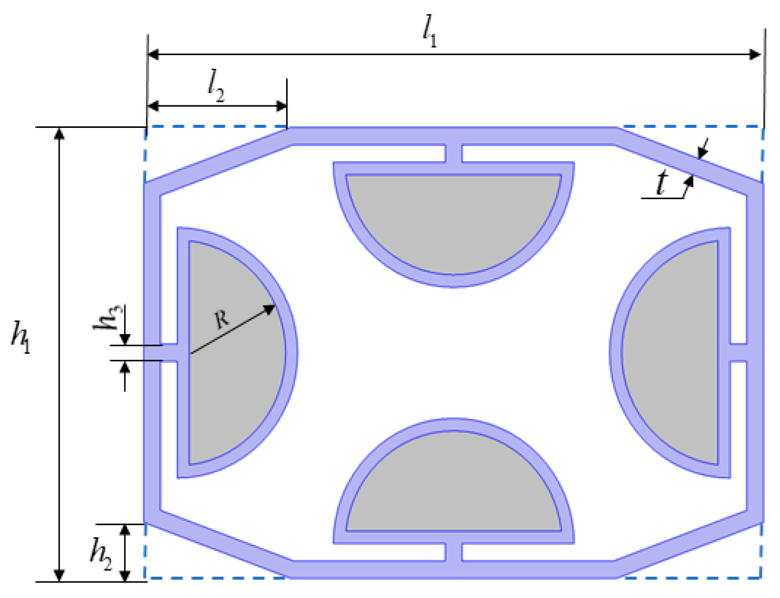
The schematic diagram of the specific structure of the material after the configuration of the mass block is shown in
Figure 7, the blue part is the titanium alloy frame, and the gray part is the lead block. Based on the original octagonal frame structure, a semicircular skeleton structure was added to fix the lead block, and together they formed a counterweight structure. Set the length of contact between the counterweight block and the siding
. Change the lead block radius
to study the relationship between the equivalent modulus of materials and the change of density.
When
, lead block radius
. Change the lead block radius
. The material equivalent density and equivalent modulus variations are shown in
Figure 8. In the process of changing the equivalent density of the material from 6.9 times the original frame material to 1.1 times, the equivalent modulus values are transformed in the range of 0.99 to 1.01 of the original modulus, which meets the requirements of the independent change of the equivalent density and the equivalent volume modulus of the pentamode material.
4. Pentamode Material Acoustic Cloak Laying Optimization and Performance Analysis
4.1. Acoustic Stealth Cloak Material Laying Method
The isomodulus variable density acoustic coordinate transformation equation is used as the theoretical basis for the laying of layered cloak materials. Set the outside diameter of the cloak as and the inner diameter as . Because the design material can achieve independent changes in density and modulus, it is only necessary to reduce the size of the frame structure to meet the equivalent modulus needs and change the lead block radius size to meet the equivalent density needs when laying the material. To simplify the structural configuration, the semicircular metal frame used to fix the lead block is omitted.
Set the outermost material cellular frame dimensions
, and lead block radius
. The pentamode material cellular is considered as a length
and height
rectangular block when laying materials. The distribution of the position of the material cells within the cloak is shown in
Figure 9. The blank part is the air domain, the gray part is the acoustic stealth cloak, and the blue part is the unit pentamode material distributed within the cloak.
is the azimuth corresponding to the element material. Define
and obtain
after rounding.
The external structure dimensions of the frame; when laying, meet the following formula:
The layered material is numbered sequentially from the outer inner, and the outermost layer is numbered as 1.
is the scaling ratio of layer
material cells relative to layer 1 material cells. The relationship between the radius of the cellular mass with the distribution location is as follows:
the density of the aqueous medium is
, the density of the lead block is
, and the density of titanium alloy frames is
. According to the above material laying method, the distribution of each layer of five-mold materials in the cloak and the specific structural parameters are shown in
Figure 10 and
Table 1.
Due to the equivalent density limitation of the titanium alloy frame structure, the lower density limit of the stealth cloak can only reach 524.14 values, so the 13th layer material element structure consists of 13 proportionally scaled titanium alloy frame structures.
The actual structure and ideal structure of the pentamode material acoustic stealth cloak are shown in
Figure 11. Layer thickness distribution and equivalent layer parameters of the homogeneous structure are the same as those of the actual structure. Because the homogeneous cloak material contains a shear modulus part, so the homogeneous cloak is a non-perfect pentamode cloak.
To study the cloak acoustic stealth performance, the simulation model is constructed as shown in
Figure 12. Where
ps represents the far-field scattered sound pressure, the incident sound pressure is replaced by the background sound pressure
pb, and PML represents the perfect matching layer that can absorb all the scattered sound waves.
When
(
is the cloak diameter,
is the wavelength of the incident sound wave at different frequencies), the actual cloak, the homogeneous cloak, and the cavity acoustic scattering effect with a radius of 0.5 m are shown in
Figure 13. The rectangular area in the figure is 10 m long, the incident acoustic wave is a plane wave, the pressure is 1 Pa, the horizontal incidence from left to right, and the gray box around it is a perfect matching layer, which is used to simulate infinite water area.
The scattering coefficient σ
s is generally used to quantify the strength of the acoustic scattering effect of the material, which is defined as the ratio of the scattered acoustic energy to the incident acoustic energy, so it can only vary between 0 and 1. To more clearly demonstrate the stealth effect of the pentamode material acoustic stealth cloak, the total scattering cross-section (TSCS) [
21] concept was introduced. TSCS is defined as the sum of the ratio of scattered acoustic power to incident power in each direction; the calculation formula is shown in Equation (21). In this paper, TSCS is characterized by calculating the square edge of the far-field acoustic pressure by integrating the square edge of the perfectly matched layer boundary. The lower limit of the incident acoustic frequency is 100 Hz, and the sampling point interval is 50 Hz. During
from 0 to 1, the TSCS values and σ
s values of the four vary with the
values as shown in
Figure 14.
The red wire corresponds to the unpaved cloak cavity, the blue wire corresponds to the pentamode material microstructure acoustic stealth cloak, the black wire corresponds to the acoustic stealth cloak containing the homogeneous structure of the pentamode material, and the green wire corresponds to the titanium alloy cylinder with a radius of 1m. The purpose of setting up the cylindrical titanium alloy control group is to eliminate the effect of acoustic diffraction and prove that the stealth effect of the pentamode material acoustic stealth cloak is not due to the phenomenon of low-frequency acoustic diffraction.
The TSCS calculation value in this paper is higher than that of other scholars, which is related to the calculation of the boundary length of TSCS, and the longer the calculated edge length, the larger the TSCS in the case of the same σs. There is a multiplier relationship between σs and TSCS, so the trend is the same for both.
From the information in
Figure 14, the stealth effect of the pentamode material microstructure acoustic stealth cloak is between the pure cavity and the homogeneous cloak, and the overall tendency is a homogeneous cloak. The acoustic stealth performance of the pentamode material acoustic stealth cloak in terms of low frequency is similar to that of the homogeneous cloak, and the total scattering cross-section has a rising trend as the frequency increases, which may be related to the scale effect of the pentamode material, and as the frequency increases, the proportion of acoustic wavelength and material cellular linearity decreases, and the effectiveness of the material as an equivalent homogeneous material decreases. Large mutations occur at
and
; this may be related to the weak shear effect of the material [
14].
4.2. Acoustic Stealth Cloak Acoustic Stealth Performance Optimization
Although the acoustic invisibility cloak laid according to the above method has a certain stealth ability, it is less effective than the homogeneous cloak under the same material parameters. To further improve the stealth effect of the pentamode material microstructure acoustic stealth cloak, it was analyzed from two aspects: optimizing the material structure and increasing the lower limit of the material density of the inner layer of the cloak.
4.2.1. Structural Microdeformation Effect Analysis
The cellular of the pentamode material is a rectangular structure, which is laid into a tightly connected circular cloak, and the rotating laying unit is constructed by using the intersection of the fan-shaped area with the dome microstructure unit of the center angle. This changes the thickness of the radial frame of the pentamode material, which affects the overall performance of the material. Considering the micro-deformation that occurs during the material laying process, the material structure is optimized, and the schematic diagram is as follows:
In
Figure 15, the solid black line is the boundary of the sector corresponding to the azimuth
, the siding on both sides of the optimization front cell exceeds the sector area, and the excess part is clipped during the process of intersection. This situation can be avoided by rotating the
-angle inward on both sides of the siding panels.
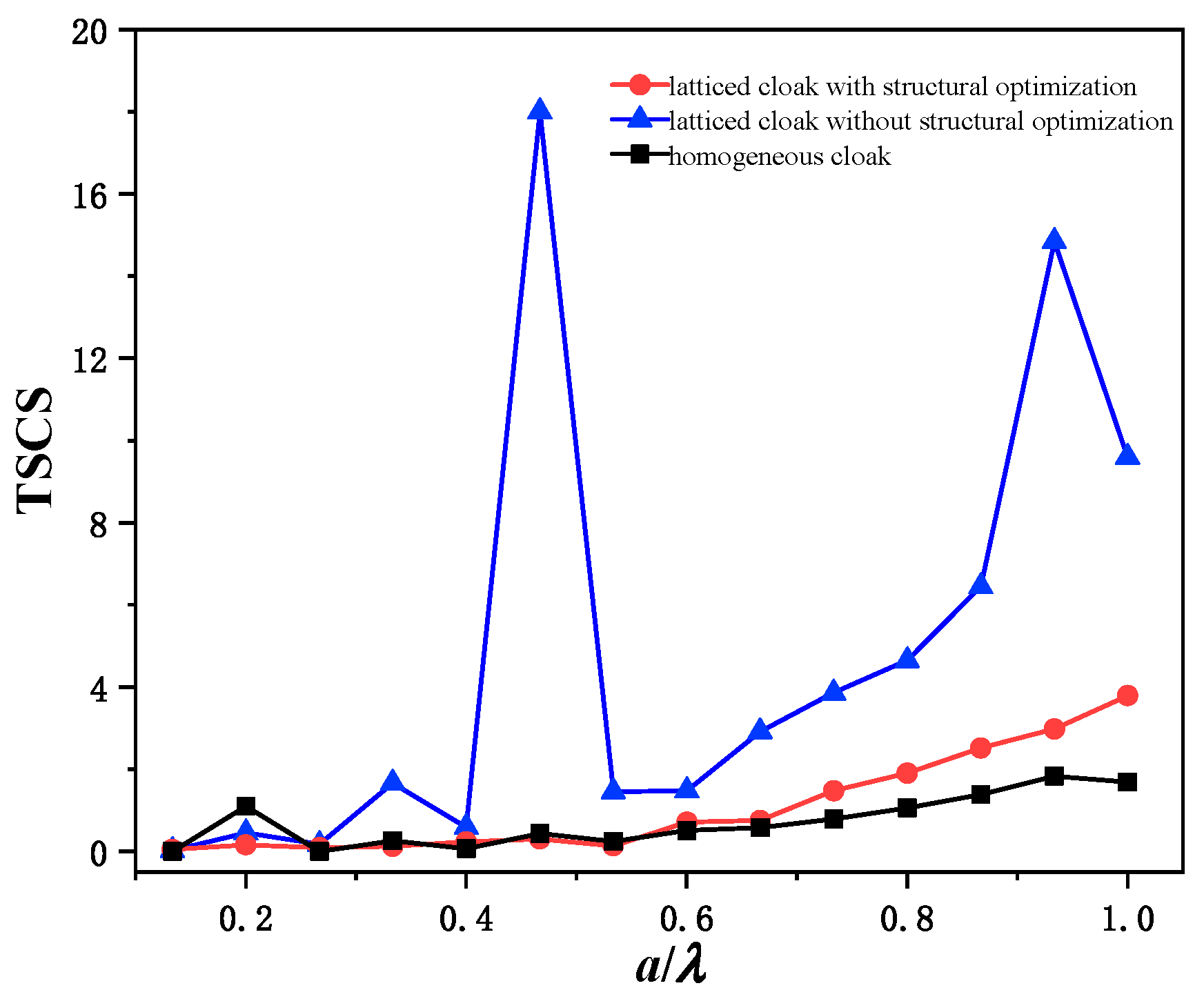
The invisibility effect of the structurally optimized material is shown in
Figure 16. After structural optimization, the overall stealth performance of the invisibility cloak is better than that of the unoptimized cloak, and the effect of suppressing acoustic scattering is obvious. TSCS decreased from 1.66 to 0.12 at
, from 18.00 to 0.31 at
, and from 14.82 to 2.98 at
. The average sampling point TSCS decreased from 4.72 to 1.09.
Compared with the TSCS of the pentamode material acoustic stealth cloak before the structural optimization, the optimized total scattering cross-sectional spectra of the homogeneous cloak are obviously more suitable. Note the cloak unit construction method that considers the micro-deformation of the structure and keeps the thickness of the siding unchanged has less influence on the material equivalent modulus.
4.2.2. Lower Density Impact Analysis
Limited by the density of the titanium alloy frame, the invisibility cloak can only be laid from the outside to the 13th layer. If the lower limit of the density of the inner layer of the cloak material can be reduced, the number of cloak layers can be increased to obtain a better acoustic stealth effect while ensuring that the outer size of the cloak is unchanged.
To study the effect of the lower density limit on the stealth performance of the pentamode material acoustic stealth cloak, the inner layer of the cloak was replaced with a T700 carbon fiber material with a higher strength. T700 carbon fiber material Young’s modulus , Poisson’s ratio , density . To ensure the equal applicability of the laying method and the consistency of the material equivalent modulus, fixed cellular material , and the optimized objective function is the same as the titanium pentamode material. After optimization, the framework structure parameters are , , and , and the equivalent density of the pure carbon fiber frame structure is only 88.07 kg/m3.
The cloak laying unit after changing the inner layer laying material is shown in
Figure 17. The 1–12 layers of the cloak remain unchanged in the original structure, and the 13–25 layers are carbon fiber base structures. Starting from layer 13, the structural parameters and equivalent modulus value distribution of each layer of materials are shown in
Table 2.
A spectrum of TSCS of the cloak after the inner layer was switched to carbon brazing is shown in
Figure 18. During
, excluding the influence of the weak shear effect, the TSCS change trend of carbon fiber-lined cloaks is about the same as that of titanium alloy-lined cloaks, and the acoustic stealth effect is slightly worse than that of titanium alloy-lined cloaks. During
, carbon fiber-lined cloaks with lower density lower limits are starting to take advantage, and the average of TSCS of the six sampling points decreased from 2.24 to 1.48. In particular, the improvement in acoustic transmission performance was most obvious at
, from 3.79 to 2.05.
The reason why the acoustic scattering effect of the carbon fiber lining cloak in the band is stronger than that of the titanium alloy-lined cloak may be related to the difference in shear modulus of the two types of materials. The equivalent shear modulus of the pentamode material based on titanium alloy is stable at about 11.09 MPa, while the equivalent shear modulus of the pentamode material based on carbon fiber is about 3.75 MPa when the two types of pentamode materials are used in combination, different shear modulus values may bring different resonant frequencies, and the resulting weak shear effect is more obvious.
The acoustic stealth effect of the carbon fiber-lined cloak in the band is better than that of the titanium alloy-lined cloak, which may be related to the scale effect. With the increase of the incident frequency of the acoustic wave, the ratio of the wavelength of the acoustic wave to the linearity of each layer of the cloak material gradually decreases, the acoustic diffraction effect is weakened, and the effect of the material structure of the inner layer of the cloak on acoustic transmission is amplified.


