Article

Effect of a Long-Range Dislocation Pileup on the Atomic-Scale Hydrogen Diffusion near a Grain Boundary in Plastically Deformed bcc Iron

1
Department of Mechanical and Aerospace Engineering, North Carolina State University, Raleigh, NC 27695, USA
2
Materials Science and Technology Division, Los Alamos National Laboratory, Los Alamos, NM 87545, USA
3
3MT Modeling and Simulation Group, Schlumberger, Sugar Land, TX 77478, USA
4
Department of Aerospace Engineering, Iowa State University, Ames, IA 50011, USA
5
Department of Mechanical Engineering and Engineering Science, University of North Carolina at Charlotte, Charlotte, NC 28223, USA
6
Department of Mechanical Engineering, Baylor University, Waco, TX 76706, USA
7
School of Aerospace and Mechanical Engineering, University of Oklahoma, Norman, OK 73019, USA
*
Author to whom correspondence should be addressed.
Crystals 2023, 13(8), 1270; https://doi.org/10.3390/cryst13081270
Submission received: 9 July 2023 / Revised: 5 August 2023 / Accepted: 9 August 2023 / Published: 17 August 2023

Abstract

:
In this paper, we present concurrent atomistic-continuum (CAC) simulations of the hydrogen (H) diffusion along a grain boundary (GB), nearby which a large population of dislocations are piled up, in a plastically deformed bi-crystalline bcc iron sample. With the microscale dislocation slip and the atomic structure evolution at the GB being simultaneously retained, our main findings are: (i) the accumulation of tens of dislocations near the H-charged GB can induce a local internal stress as high as 3 GPa; (ii) the more dislocations piled up at the GB, the slower the H diffusion ahead of the slip–GB intersection; and (iii) H atoms diffuse fast behind the pileup tip, get trapped within the GB, and diffuse slowly ahead of the pileup tip. The CAC simulation-predicted local H diffusivity, D pileup tip , and local stresses, σ , are correlated with each other. We then consolidate such correlations into a mechanics model by considering the dislocation pileup as an Eshelby inclusion. These findings will provide researchers with opportunities to: (a) characterize the interplay between plasticity, H diffusion, and crack initiation underlying H-induced cracking (HIC); (b) develop mechanism-based constitutive rules to be used in diffusion–plasticity coupling models for understanding the interplay between mechanical and mass transport in materials at the continuum level; and (c) connect the atomistic deformation physics of polycrystalline materials with their performance in aqueous environments, which is currently difficult to achieve in experiments.

1. Introduction

Compared to rail, trucks, and tankers, oil pipelines remain as the most effective means for crude oil transportation in terms of route flexibility and transport efficiency. As a mixture of solid, liquid, and gaseous phases, crude oil contains sediments, water, salts, carbon monoxide, and acid gases such as H 2 S. The presence of H 2 S facilitates H diffusion into pipeline steels and interaction with material defects, such as dislocations and grain boundaries (GBs), resulting in hydrogen-induced cracking (HIC) and then oil leakage. It has been reported that more than 50% of the failures experienced in the oil and gas production industry are caused by HIC in oil pipelines [1]. In order to combat oil spills, a computational framework that can predict the onset of HIC in polycrystalline oil pipeline materials is needed. To date, such a predictive computational framework, however, has not been well established due to an intrinsic complexity associated with the coupling between dislocation plasticity and HIC, which occurs across a broad range of length scales. That is: (a) the H-enhanced localized plasticity (HELP) [2,3] spanning tens of micrometers when a large number (tens or hundreds) of dislocations are blocked by an atomically structured GB [4,5,6]; (b) the buildup of a high internal stress field ahead of such a microscale pileup, not decaying to zero until several micrometers away from pileup tip [7,8]; and (c) the H-enhanced decohesion (HEDE) [9] of the GB at the atomic scale if such a long-range high internal stress cannot be fully relieved by a dislocation cross-slip, transmission, twinning, phase transformation, hydride formation, and so on [10,11,12]. Clearly, a mechanistic understanding of the fundamental mechanisms underlying HIC in plastically deformed polycrystalline materials necessitates computer simulations ranging from the atomistic up to the continuum level.
At the atomic scale, molecular dynamics (MD) has been one of the most powerful tools for studying H diffusion, dislocation motion, GB structure evolution, and their interaction. Through tracking the motion of each atom in the simulation cell, MD captures the atomistic nature of materials. To understand HIC, extensive MD simulations have been performed to: (1) provide direct evidence that H diffuses significantly more slowly around a screw dislocation core than it does in lattices away from the core [13]; (2) quantify the effects of dislocation types, GBs, and triple junction structures on the H diffusion barrier [14,15]; (3) discover a new mechanism responsible for the ductile-to-brittle transition in bcc iron, referred as H aggregation-suppressed dislocation emission from the crack tip [16]; (4) help explain the H-induced pop-in load reductions in the force-depth curves of a H-charged sample under indentation [17,18]; (5) identify the possible interstitial H sites at a given GB by dividing it into polyhedral packing units, with the H segregation energies at these sites being calculated and then fed into the Rice–Wang thermodynamic theory of interfacial embrittlement [19]; (6) survey the possible nanoscale mechanisms responsible for HELP through quantifying the effects of H on edge dislocation mobility [20]; and (7) analyze the interactions between dislocation and the H-segregated GB [21]. Despite their great popularity, the results from MD simulations need to be understood cautiously because, due to the high computational cost, typical MD simulations employ only a single or a few dislocations very near a GB embedded in a simulation cell with a limited volume [21,22,23,24]. With such a nanoscale simulation cell, the dislocation density becomes unrealistically high. In addition, in many MD simulations, only equilibrium GBs (EGBs) composed of periodic structural units have been considered. As a consequence, the long-range structural heterogeneity of non-equilibrium GBs (NEGBs), especially GBs charged with H, has been cut off. In such a scenario, the stresses induced by the periodic images of dislocations or NEGBs are non-negligible, which may have polluted the results [24,25]. As such, nanoscale MD simulations alone might not be sufficient if one relies on them to develop/calibrate higher-scale constitutive rules for predicting how H-charged polycrystalline materials behave in engineering practice. In contrast, continuum models have the ability to be scaled up in length. In the past several decades, a variety of such models have been developed. Here, we categorize them into four types, as shown below.
Type I: One-way coupling models without considering the underlying grain structures. This type of model was pioneered by Sofronis and co-workers [26,27,28]. In such models, the H diffusion is considered in conjunction with the material’s elasto-plastic deformation. A two-field (material deformation and H concentration) boundary value problem is formulated. As a first step in such approaches, the traditional elasto-plastic constitutive rules, such as J2 flow rules, are used during solving for the displacement, strain, and stress fields. Thereafter, the H diffusion equation is solved to determine how H distribution evolves under these stresses and plastic strains. Numerically, this is realized via the standard procedures in finite-element (FE) software, such as ABAQUS, through two steps: (a) computing the displacement, strain, stress, and their gradient by implementing UMAT subroutines; and then (b) solving the H diffusion equation for the H distribution by implementing UMATHT subroutines, which impose UMAT-based hydrostatic stress and plastic strains on the diffusion. Such models are believed to be “one-way coupling” models because only the deformation upon H diffusion is considered, while the H-affected material properties are not. Clearly, such models were built upon four assumptions: (i) the material microstructure complexity is not explicitly included; (ii) the H in these models is considered to reside at either normal interstitial lattice sites (NILSs) or trapping sites (GBs, dislocation cores, and so on), and the H occupancies at NILSs and these trapping sites are considered to be always in equilibrium according to Oriani’s theory [29]; (iii) there is no communication between these trapping sites; and (iv) only the reversible shallow traps are taken into account, and thus the models can be used to estimate the plastic-strain-induced concentration of H trapped at dislocations only. All the deep traps, such as GBs, are assumed to be always filled with H, which may not be the case in reality.
Type II: Two-way coupling models without considering any underlying grain structures. As an extension of Type-I models, in such Type-II approaches, the effect of H on the material properties is considered by including the H-induced volume dilatation or flow stress reduction in the framework [30,31,32]. By accounting for the effect of H on the material’s constitutive response, such models can capture the onset of plastic instability in a H-charged material under deformation. The predictive capability of these models is, however, still limited, because in addition to the same assumptions as those in Type-I models, these models further assume that H always induces a flow stress reduction and deformation localization. From the microscopic point of view, this assumption was based on the fact that the presence of H will only enhance the mobility of dislocations. However, according to recent MD simulations [20], this might not be the case. From the macroscopic point of view, this assumption implies that the presence of H will always cause material softening. This is inconsistent with the results from many experimental studies, where both H-induced hardening [33,34] and H-induced softening [2,35,36,37,38,39] have been observed.
Type III: One-way coupling models for polycrystalline materials with the underlying grain structures being explicitly included. In these models, H transport and elasto-plasticity are simulated through coupling diffusion with the crystal plasticity finite-element (CPFE) method [40,41,42,43,44,45,46]. Specifically, the effects of hydrostatic stress and plastic strain on H transport are considered when solving the diffusion equation, while the H-induced material property changes are not considered in the CPFE method. Such approaches have similar limitations to those of Type-I models but are superior in one aspect: H diffusion is linked to the stress fields calculated from CPFE analysis, rather than those based on the standard J2 theory [47,48,49]. With the elasto-plastic anisotropy being accommodated, these models may be used to assess the effects of the material microstructure on H diffusion, although only in a qualitative sense due to their "one-way coupling" nature together with a neglect of the H diffusion along dislocations and GBs.
Type IV: Two-way coupling models with the underlying grain structures being explicitly retained [50,51,52,53,54,55]. If one desires to capture all the salient features of HIC, a fully two-way coupling model is needed. It should contain at least four components: (1) an explicit accommodation of the complex grain structure to characterize the heterogeneous internal stresses; (2) a decoration of the diffusion model with local stresses/strains for simulating the H occupancy equilibrium between NILSs and trapping sites in materials under deformation; (3) a set of constitutive rules for describing the H-induced material softening/hardening [32,56], GB cohesive strength reduction [50,51,52], and so on; and (4) the local stress-/structure-dependence of the H diffusivity, such as pipe diffusion along dislocations and GBs. Nevertheless, to the best of our knowledge, such a fully two-way coupling model equipped with all of these four components does not exist yet. Existing models usually include only a few of them. For instance, in a pioneering work by Rimoli and Ortiz [50] and a recent work by Pu et al. [52], a CPFE model for polycrystals, a Fisher model for GB diffusion, and a cohesive zone model for intergranular fractures were all integrated together, but with a consideration of neither pipe diffusion nor the H concentration dependence of CPFE model parameters. Moreover, even with all the above four components being implemented, Type-IV models still require the constitutive rules, such as the H-concentration-dependent CPFE model parameters, GB cohesive strength, and the local-stress-dependent GB diffusivity, to be carefully calibrated from either experiments or fine-scale simulations. This is non-trivial but is definitely necessary if one desires to achieve a high predictive capability.
Overall, neither continuum nor atomistic models alone can capture the full complexity of the interplay between H diffusion, dislocation plasticity, and subsequent HIC. Multiscale models are needed to overcome the many inherent difficulties in these phenomena. To meet this need, the concurrent atomistic-continuum (CAC) method developed in [57,58,59,60,61] was deployed herein. The CAC model is effective in predicting: (i) the heterogeneous stress field evolution in polycrystalline SiC with dopants on the GB [62] and (ii) the formation of a microscale dislocation pileup followed by atomic-scale dislocation transmission [63], twinning, and phase transformations (PTs) [64]. In this study, taking plastically deformed bi-crystalline bcc iron as a model system, the H diffusion at an atomically structured GB under the effect of a nearby 0.2 μ m long dislocation slip was simulated by the CAC method. With the interatomic potential being the only constitutive rule, at a fraction of the cost of full MD simulations, the coupled dynamics between the microscale dislocation slip, the long-range internal stress buildup, and the atomic-scale H diffusion at the GBs was characterized. In the rest of this paper, we first briefly introduce the model setup in Section 2. Simulation results are then presented in Section 3. Thereafter, we conclude this paper with a summary of the major findings and a discussion of future research in Section 4.

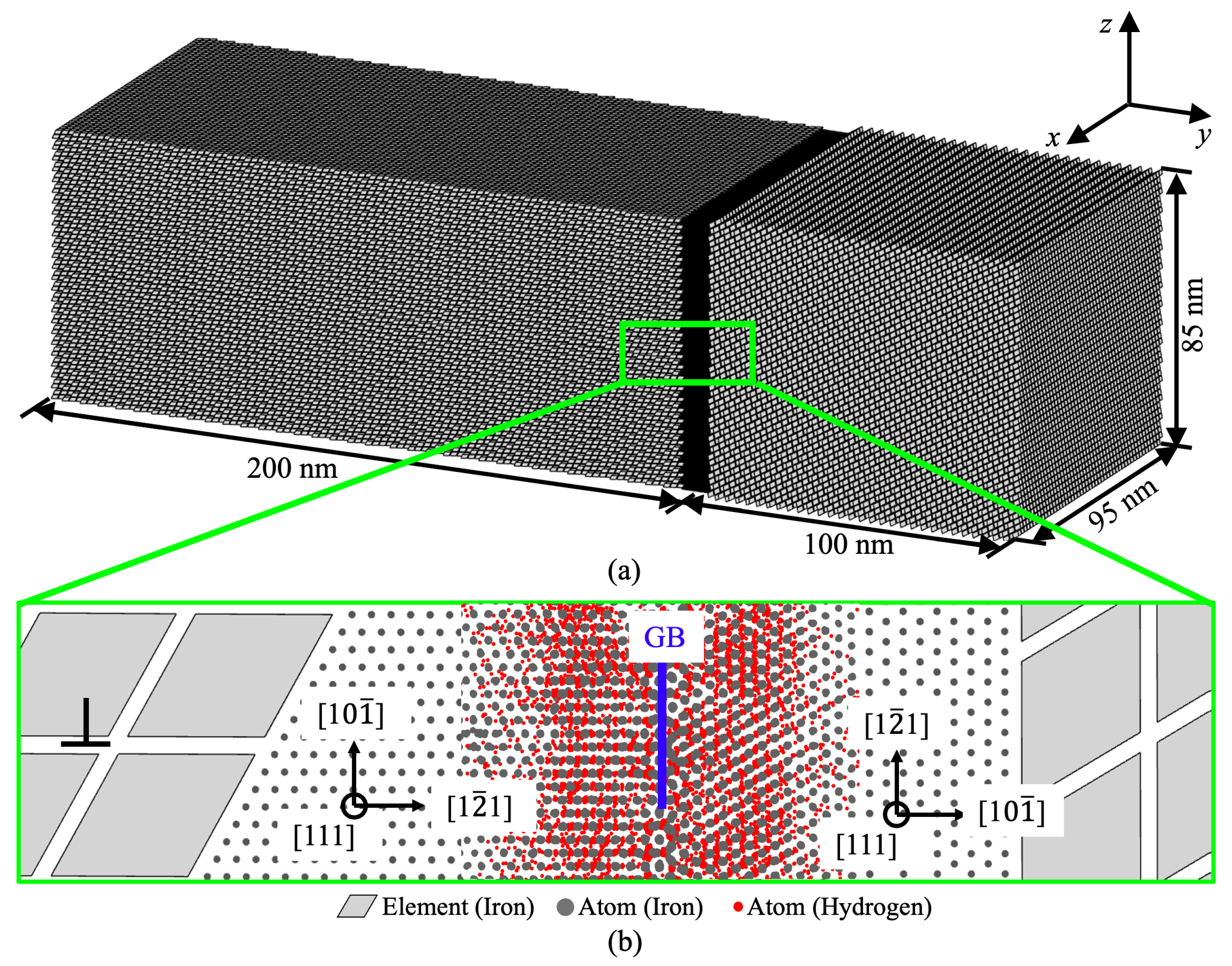
2. Computer Model Setup

The CAC model for a bi-crystalline bcc iron sample containing a GB charged with H is shown in Figure 1. One main novelty of such a CAC model is that it bridges several length scales relevant to HIC in one single model. It explicitly accommodates the GB at an atomistic resolution alongside the lagging dislocations away from the GB in a coarse-grained (CG) description using finite elements (FEs). On one hand, retaining the GB structural and chemical complexities at the atomic scale is important because the cause of failure or crack initiation in different alloys with different GB chemistries/structures may differ substantially. For instance, GB failure/crack initiation was found to be controlled by stresses in Ti alloys but by energy in Ni-based superalloys [65]. On the other hand, the majority of the atomistic degrees of freedom (DOF) are eliminated by assuming collaborative deformation at the lattice-cell level in the CG domains, where the displacements of atoms are constrained by the FE nodal displacements. It should be noted that the size selection of the FEs did not bias the simulation results in this work. Although the dislocation core structures and stress fields may not be precisely captured in the continuum domain due to the deployment of FEs, they become exactly the same as those from full MD simulations when dislocations migrate into the domain near the GB, where the fully atomistic resolution has been retained. Evidence of this can be found in [66]. Such a computational setup is multiscale in nature and has two unique features: (i) it requires the interatomic potential as the only constitutive rule, such as the EAM potential for the Fe–Fe and Fe–H interactions [16] used in this work; and (ii) it can be scaled up to microns and even higher while retaining an atomistic resolution near the critical region (the GB in this work) in the materials. A variety of defects, including screw/edge dislocations, twist/tilt GBs, and crystallographic orientation-dependent phase boundaries (PBs) can be all constructed as desired. This is important because different GBs have different diffusive properties due to their diverse atomic structures. For instance, Σ 3 and Σ 5 GBs are known to have different H diffusion properties. The capacity of the CAC model to retain the atomistic resolution on the GBs enabled us to characterize the atomic structure dependence of the GB diffusivity. Such information was then passed into greater-length-scale models, such as the CPFE model, which usually assumes a constant diffusivity for all GBs. A comprehensive survey of the long-range dislocation pileup-affected diffusivity of many different GBs through systematic CAC simulations will be performed and reported in a separate work. Here, we only present the results for one particular random GB to demonstrate a concept. It should be noted that the H segregation from the far region into the GB was not simulated here. As such, a certain number of H atoms at a concentration of 0.5% were directly introduced into a region in the vicinity (4 nm on both sides) of the atomically structured GB.
The lattice orientations were chosen to be x [ 111 ] , y [ 10 1 ¯ ] , and z [ 1 2 ¯ 1 ] in the left grain, but x [ 111 ] , y [ 1 2 ¯ 1 ] , and z [ 10 1 ¯ ] in the right grain. In this way, one slip plane, along which the dislocation pileup was formed in the left grain, was along the y direction and perpendicular to the GB plane. The crystalline grains in the domains 4 nm away from the GB were discretized into coarse FEs. Each FE contained 512 atoms. These FEs were carefully configured (see details in [61]). They could slide with respect to each other to accommodate the dislocation slip along the FE boundaries. Such a CG description of dislocation was shown to be the first model of its kind that could capture the collective behavior of many micrometer-long dislocation lines without smearing out the atomic-level kink dynamics along each of them [61]. For the sample with dimensions of 95 nm × 300 nm × 85 nm, the CAC model contained 381,000 FEs in the two grains and 5.9 million atoms on the GB, which is equivalent to 201 million atoms in a full MD model. In this way, the number of computational degrees of freedom in such a CAC model is only 5% of that in full MD simulations. This, in turn, provided us with opportunities for quantifying how a pileup containing a few to tens of dislocations could affect the atomic-level H diffusion at the GB.
A queue of uniformly separated dislocations were initially introduced into the middle plane of the left grain (see the one dislocation near the GB in the inset picture of Figure 1). As demonstrated in our previous work [57], because the CG domain in a CAC model can accommodate dislocations without smearing out their atomistic natures, the dislocations were built into the CG domain by displacing FE nodes according to the elasticity-based solution for the displacement field around a screw dislocation. Different from traditional FE models, in which the neighboring elements are connected by sharing nodes, the FEs in CAC models across the slip plane are disconnected (see the zoomed-in view of the inset picture in Figure 1). Thus, the displacement jump induced by a dislocation along the slip plane is allowed. Due to the deployment of FEs, the dislocation density in this work could be at the level of 10 14 /m 2 , which is two orders of magnitude higher than that commonly observed in experiments ( 10 12 /m 2 ), but two orders of magnitude lower than that obtained in typical MD simulations ( 10 16 /m 2 ). More importantly, the model that we present here was just a prototype, and was created using modest computational resources. It could be further scaled up in length to achieve an experimentally comparable dislocation density if intensive computational resources are used. After dislocations were introduced into the model, the upper and bottom boundaries of the model were moved along the x [ 111 ] plane, but in the opposite direction to impose a shear on the sample. After the increase in each shear strain, the top and bottom ends of the sample were then fixed for a finite duration to equilibrate the dislocation configuration in the pileup. Since the H diffusion at the GB was the focus here, a temperature of 300 K was imposed on the system and maintained as a constant. It should be noted that, although a phonon-dynamics-based finite-temperature CG model [61] has recently been developed, the constant temperature in this work was realized through a velocity rescaling scheme (the FE nodal velocities in the CG domain and the velocities of the atoms in the GBs were scaled together towards a desired temperature) for simplicity. A time step of 0.001ps was deployed for the time integration in both the atomistic and CG domains.

3. Simulation Results

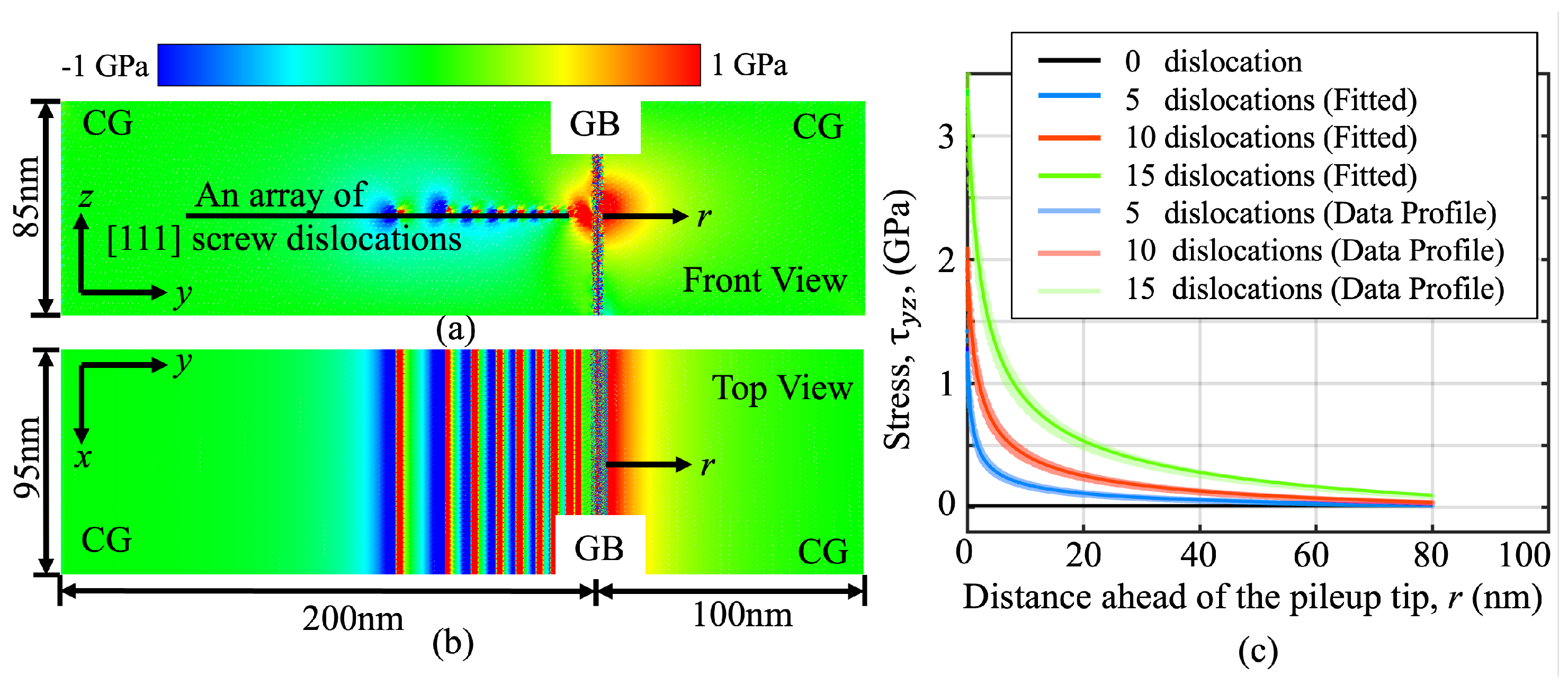
3.1. The Dislocation Pileup-Induced Internal Stress near a H-Charged GB

Due to the large geometric mismatch between the two grains, the random GB under consideration here acted as a strong barrier against dislocation motion. As a consequence, the equilibration of the current model under shear stress led to the formation of a pileup. The separation between dislocations in this pileup was several nanometers near the GB but gradually increased up to tens of nanometers in the region away from the GB. Unsurprisingly, a progressive pileup led to an obvious local stress concentration. The distribution of instantaneous shear stress ( τ y z ) viewed along the dislocation line direction and also within the slip plane is presented in Figure 2a,b, respectively. To understand the stress contour in Figure 2a,b, two clarifications need to be noted: (i) Figure 2a shows a view of the stress field along the dislocation line direction; (ii) Figure 2b presents a view of the stress field within the slip plane. Around each dislocation line, one side is blue, suggesting a negative shear stress, and one side is red, indicating a positive shear stress, respectively. This is typical for the stress around a screw dislocation. It was also noted that, due to the presence of the GB and the formation of a pileup, the symmetry of the stress field around each dislocation is broken. Since H was only introduced ahead of the pileup tip at the GB, where the positive shear stress (red) dominates, the repeating negative and positive shear stress distribution behind the pileup tip do not have a substantial effect on the H diffusion at the GB.
Although a dislocation pileup is formed only under a very low applied shear stress, once formed, stresses with a significantly higher magnitude than the applied shear can develop at its spearhead. To characterize the dislocation pileup-induced internal stress profile, the material domain ahead of the slip–interface intersection was divided into a series of finite-sized volume elements, each of which had dimensions of 0.5 nm × 0.5 nm × 0.5 nm. These are significantly smaller than the dimensions of an FE. The stresses acting on each volume element were calculated through: (i) mapping out the stresses acting on each atom within each volume element, which result from an interpolation of the FE nodal stresses; and (ii) summing up the stress on those atoms and dividing it by the number of atoms in the volume element. This represents one of the main features of CAC simulations that has often been used in our previous publications [63,64]. The stresses acting on each volume element could then be calculated and plotted as a function of its distance away from the pileup tip (Figure 2c). Similar to our previous results from 2D simulations, the two main observations here were as follows: (a) the CAC simulation successfully captured the local stress concentration at up to 3 GPa when the number of the dislocations in the pileup, denoted as n, increases from 5 to 15; (b) this local stress concentration does not decay to zero at a site 80 nm away from the pileup tip when n = 15, a distance that can be even longer when n > 15.
The stress profiles in Figure 2c could then be fit to an equation according into the theory of Eshelby, Frank, and Nabarro [67]:
τ y z = τ 0 + K ( r + r 0 )
where K describes the intensity ahead of the slip–GB intersection; r is the distance away from the pileup tip at the GB; τ 0 is introduced to accommodate uncertainty regarding the stress state at a reference point; and r 0 is introduced to indicate the position where the maximum stress concentration occurs. Fitting the data resulting from CAC simulations into Equation (1) enables the quantification of the stress intensity factor, K, and its dependence on the number of dislocations (see Table 1).

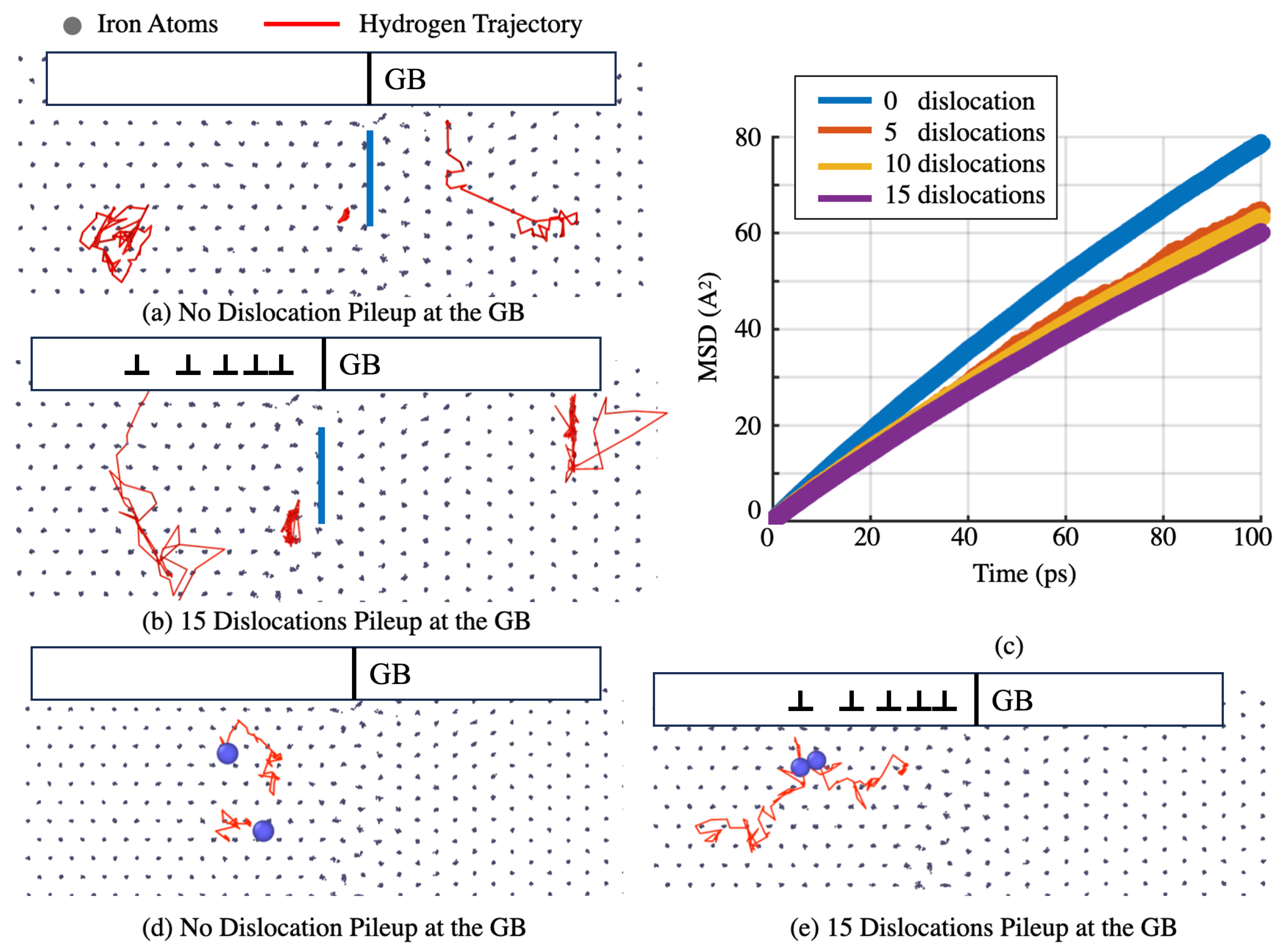
3.2. H Atom Diffusion near the Slip–GB Intersection

As mentioned before, the CAC simulation allows us to quantify how the long-range plastic flow affects the atomic-level H diffusion near the GB because: (i) the FE model for the material domain far away from the GB enables the simulation to accommodate the long-range plastic flow mediated by a large number of dislocations; and (ii) the fully atomistic resolution at the GB facilitates us to explicitly track the motion of each H atom, from which the GB diffusivity can be directly calculated. As a demonstration of this capability, Figure 3a,b present the trajectories of three H atoms in a domain near the slip–GB intersection when 0 and 15 dislocations are piled up, respectively. It should be noted that, for the purpose of comparison, the trajectories in both Figure 3a,b were recorded within the same duration. They were all projected on an initial atomistic configuration containing no dislocations near the slip–GB intersection. In this way, the H diffusion trajectories with respect to the same atomistic structure can be clearly visible. Three main observations from Figure 3a,b are: (i) within the same time window, the H atoms behind the pileup tip in the left grain diffuse significantly farther when n = 15 than when n = 0 (see the left trajectories in Figure 3a,b); (ii) by contrast, the H atoms ahead of the pileup tip in the right grain diffuse considerably less when n = 15 than when n = 0 (see the right trajectories in Figure 3a,b); and (iii) the H atoms within the GB (see the middle trajectories in Figure 3a,b) do not diffuse much when compared with the H atoms in the left and right grains for both n = 15 and n = 0. This is consistent with the notion of considering the GB as a deep trapping site for H.
To determine the H diffusion coefficient at the slip–GB intersection when different numbers of dislocations participate in the pileup, we measured the mean square displacement (MSD) of those H atoms, calculated the H diffusion coefficient, and connected it with the pileup tip stress intensity factor at n = 0, 5, 10, and 15. In detail, we calculated the MSD of the H atoms ahead of the pileup tip over a finite duration and then the diffusion coefficient, D, as follows:
D = lim t 1 6 N i = 1 N < | x ( t ) x ( 0 ) | 2 > = 1 6 lim t 1 N i = 1 N | x ( i ) ( t ) x ( i ) ( 0 ) | 2
where n is the number of H atoms ahead of the pileup tip, and x ( t ) is the position of the ith H atom at time t with respect to a reference position at x ( 0 ) .
Figure 3c shows the MSD curves resulting from such calculations within a duration of 100 ps. Note that, when a particle (here, a H atom) is in diffusive motion, its MSD is linearly proportional to the diffusion coefficient. Using the MSD curves in Figure 3c, we measured the local H diffusion coefficient as the slope of each MSD curve. The extracted H diffusion coefficients are summarized below. Clearly, the more dislocations piled up at the GB, the higher the stress intensity and the lower the H diffusion ahead of the pileup tip. In detail, the shear stress at 3 GPa ahead of the pileup tip seems to reduce the H diffusivity at the GB by 30%. The simulation-predicted diffusivity reduction at the pileup tip implies a new mechanism: the plasticity-induced clustering of hydrogen (PICH). A combination of this mechanism with many previously reported mechanisms might contribute to hydrogen embrittlement through four steps: (1) the H-enhanced localization of plasticity (HELP), i.e., H-promoted dislocation pileup formation (not modeled in this work but widely reported in the literature); (2) the accumulation of H at the slip–GB intersection through the PICH mechanism; (3) hydrogen-enhanced de-cohesion (HEDE) at the GB; and (4) hydrogen-induced cracking (HIC). We believe that HEDE is only possible after the process of PICH, because HEDE demands the accumulation of a large population of H in a local region at the GB. We will provide more direct evidence of this in our future publications. To confirm the occurrence of PICH, we chose several pairs of H atoms and monitored the relative distances between the two atoms in each pair. The results showed that the separation between the two H atoms in each pair decreased upon an increase in the number of dislocations in the pileup. Figure 3d,e present the typical trajectories of two H atoms in one pair near the GB when n = 0 and n = 15, respectively. It is seen that the two H atoms get significantly closer with respect to each other when n = 15 than what has been observed when n = 0.

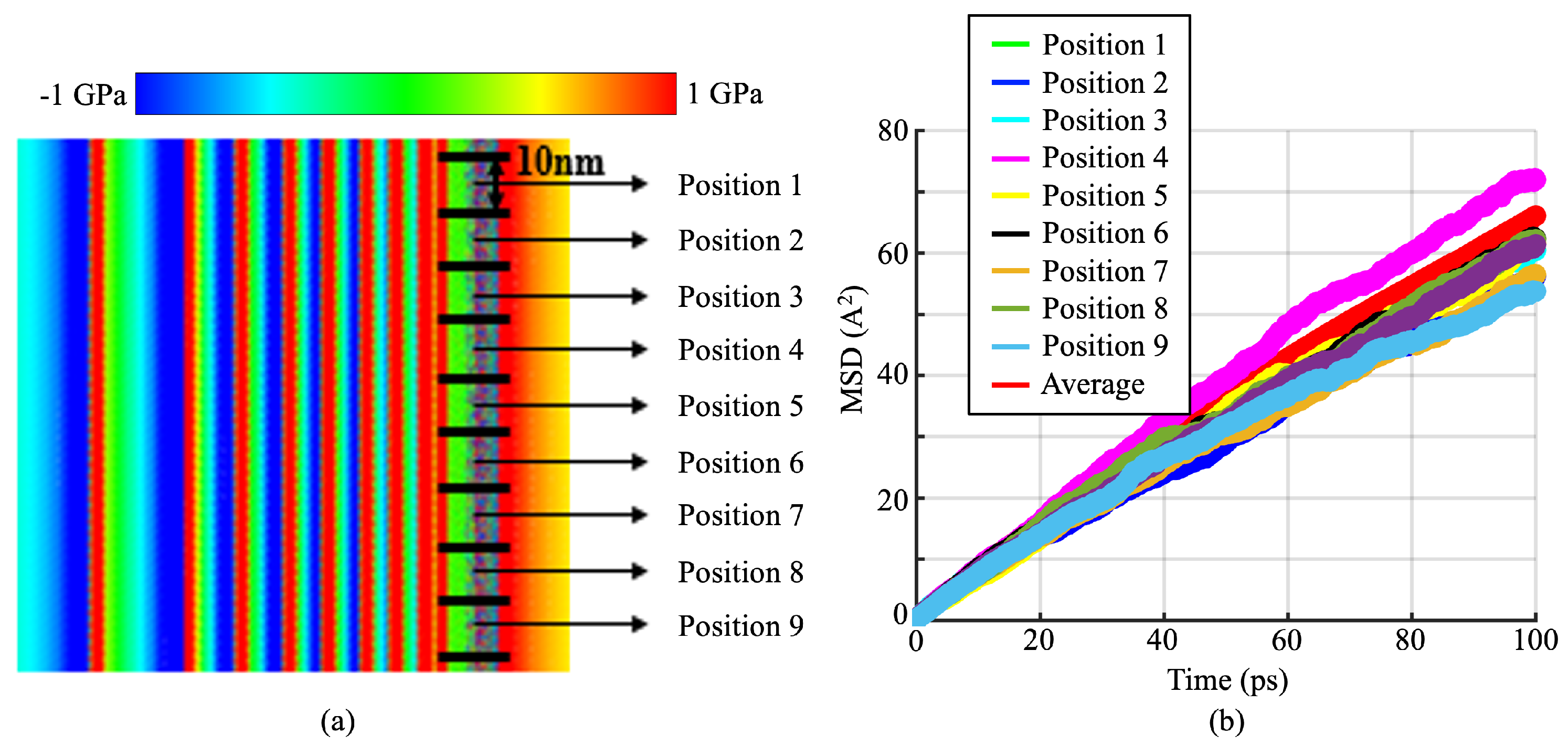
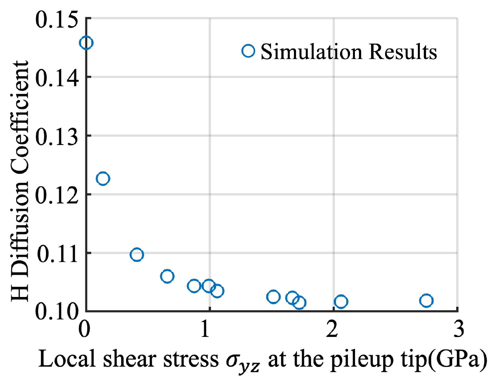
3.3. H Diffusion Heterogeneity and Its Dependence on Local Stresses

In contrast to many existing full MD or continuum models/theories [26,27,28], which either only considered very short dislocation segments or were formulated in a plane–strain framework by assuming homogeneity along the dislocation line, the present CAC model is fully three-dimensional and thus can be used to characterize the heterogeneity of the stresses/diffusivity along very long dislocation lines. As a preliminary demonstration, Figure 4a presents the instantaneous local shear stress distribution within the slip plane resulting from CAC simulations of the pileup of fifteen 95 nm dislocations at an atomically structured GB. The H diffusion and stress heterogeneity along the dislocation line direction were then characterized by: (i) dividing the pileup tip material domain along the line direction into nine bins, each of which had a width of 10 nm; (ii) calculating the MSD of the H atoms in each bin as shown in Figure 4b and extracting the slope of each of these MSD curves as the local diffusion coefficient; (iii) fitting the stress profiles ahead of each of these nine bins into Equation (1); and (iv) correlating the obtained local diffusion coefficients, the local stress intensity factors, and the positions of the nine bins with each other. The data resulting from the above four steps shows: (a) both the local diffusion coefficients and stress intensity factors could fluctuate by more than 20% around the averaged values, although these fluctuations might have been suppressed/amplified if a larger/smaller bin width was deployed in Step 1; (b) for all the nine positions under consideration here, there exists a good correspondence between the local stress intensity and local H diffusion coefficient, i.e., the higher the stress intensity, the lower the diffusion coefficient. This finding motivates us to develop a mechanics model, as shown below, to describe the local stress-dependent diffusivity ahead of the pileup tip near the GB.
Similarly to the Oriani theory [29], considering the material domain ahead of the pileup tip as H-trapping sites, the H diffusion coefficient within them can be expressed as
D pileup tip = D 0 f ( σ , T ) ,
where D 0 is the H diffusion coefficient at the NILSs under zero stress, σ is the local stress, and T is the temperature. The ratio function of f ( σ , T ) is used here to include the effects of σ on D pileup tip by considering the dislocation pileup as an Eshelby inclusion. It can be written as
f ( σ , T ) = 1 1 K d + K d exp ( E Binding ) / R T ,
where R is the Boltzmann constant, T is the temperature, K d is the pileup tip trap density (the ratio between the number of pileup tip trap sites and the total number of trapping sites), and E Binding is the H-binding energy at the pileup tip. The H-binding energy at such trapping sites was assumed to follow the form of Eshelby transforming energy dissipation [68,69,70]. If only the first-order interaction between H and the trapping site is considered, E Binding can be expressed as σ k k V i n c l , where σ k k is the hydrostatic stresses. Here, to include a consideration of the effect of the shear stress, E B i n d i n g is expanded as:
E B i n d i n g = ( σ i j + 1 2 σ i j T ) ε i j * V incl
with ε i j * being the local strain associated with the finite-sized volume V i n c l in a material domain with dimensions of 0.5 nm × 0.5 nm × 0.5 nm ahead of the pileup tip, and σ i j and σ i j being the local stresses and the stress (if there is any) in the far field, respectively. An insertion of Equation (5) into Equation (4), and then Equation (4) into Equation (3), leads to the following expression for the dislocation pileup tip H diffusion coefficient:
D pileup tip = D 0 1 K d + K d [ ( σ y z + 1 / 2 σ y z ) ε y z * V incl ] / R T
with σ y z being the shear components of the stresses ahead of the pileup tip, and all other stress components being negligible in the current computational setup.
Since D pileup tip , σ y z , and ε y z can all be directly measured from the CAC simulations, a fitting the CAC-simulation-predicted D pileup tip at chosen sites (such as position 5 in Figure 4a) ahead of the tip of pileups containing different numbers of dislocations enables us to determine all the model parameters in Equation (6). A direct correlation between the pileup tip local stress ( σ y z ) and the pileup tip H diffusion coefficient (see Figure 5) can be established. The incorporation of such information extracted from CAC simulations into higher-length-scale models, such as the continuum-level CPFE, will be tested and reported in a separate work.

4. Summary and Discussion

To summarize, in this work, a multiscale computational analysis of the effects of a long-range dislocation pileup on the H diffusion near an atomically structured GB in a plastically deformed bi-crystalline bcc iron sample was performed. The present simulations go beyond not only nanoscale MD models by scaling up in length to accommodate tens of long dislocations using a novel CG description away from the GB, but also continuum models by retaining a fully atomistic resolution near the GB. Our main findings were: (i) The local shear stress concentration induced by a pileup containing a large number of screw dislocations can be as high as 3 GPa, although it might be slightly relaxed by the atomic-level H diffusion nearby. (ii) The H diffusivity behind the pileup, at the pileup tip, and ahead of the pileup tip should be differentiated. The H atoms diffuse faster behind the pileup tip due to pipe diffusion along the dislocations arriving at the GB, get trapped at the pileup tip due to the presence of deep trapping sites within the GB, and diffuse significantly slow ahead of the pileup tip due to the notable stress concentration there. The slow H diffusion ahead of the pileup tip implies the plasticity-induced clustering of H atoms (PICH). This may be one important intermediate step during the process of HIC. (iii) Both the local stresses and H diffusivity ahead of the pileup tip exhibit strong heterogeneity along the dislocation line direction. Most importantly, the local stress-dependent GB diffusivity ahead of a pileup tip can be fit into a model with its parameters being well-calibrated via CAC simulations. This is one main outcome of this research, because such local stress-based models for long-range pileup-affected GB diffusivity are rarely considered in MD simulations at the atomic scale or continuum-level simulations at the macroscale.
In spite of these interesting findings, the present CAC simulation results should also be taken with great caution due to the following limitations of this study: (1) Although our CG model was recently shown to be able to accommodate not only dislocations but also H diffusion along the dislocation, neither the H atoms carried by the dislocations away from the GB nor their segregation from the far region into the GB region were directly simulated here. The reason is: such a H segregation or deposition process is significantly slower than the dislocation pileup. The capture of the dislocation pileup formation together with the H migration from the far region into the GB region necessitates a combination of CAC simulations with the kinetic Monte Carlo (kMC) method, which is still under development. (2) The constant temperature of 300 K in the present simulations was simply realized by scaling the velocities of the atoms near the GB together with the FE nodal velocities in the CG domain away from the GB, which may have induced a mismatch in the phonon dynamics between the atomistic and the CG dscriptions of materials. The effect of such a phonon dynamics mismatch on the H diffusivity at the GB is unclear and will be carefully quantified in our future work by implementing either the lattice-dynamics-based FE shape function or the phonon density of the states-based finite temperature algorithm in the CG domain [61]. (3) The observed clustering might have resulted from the artifacts of the EAM potential deployed here. A confirmation of this will require the implementation of high-fidelity potentials, such as the machine learning (ML)-based potential [71], to describe the Fe-Fe, Fe-H, and H-H interactions with an accuracy comparable to that of quantum mechanical calculations. The ML-based potential was recently implemented in a CAC simulation in [72] and will be expanded for the problem under consideration here.
From a computational point of view, to characterize the coupled dynamics between slip transfer and HIC, the simulation tool needs to not only accommodate the microscale dislocation pileup together with the atomic-scale diffusion, as shown in this work, but also allow a dislocation migration away from the GB once it transmits, cross-slips, or gets reflected by the GB. Otherwise, the dislocations will be “jammed” at the slip–GB intersection and will “pollute” the subsequent microstructure evolution. To meet this need, we recently developed an adaptive mesh splitting algorithm and implemented it in a CAC. It splits the FE along the slip plane at which the outgoing dislocations migrate. It does not need a refinement of all the coarse FEs into fully atomistic resolution along the dislocation migration path and thus retains the computational gain over full MD simulations. As a demonstration of its capabilities, we performed adaptive CAC simulations of slip transfer together with atomic-scale structure reconfiguration on the GB [63]. Our preliminary results showed that the pileup-induced local stress at the slip–GB intersection relaxed upon the occurrence of transmission. Correspondingly, the GB structure evolved towards a lower configuration energy state but could be metastable when more dislocations arrived at the GB. This suggested that the energy barrier of the GB is indeed an important parameter. However, its deployment as a metric for detecting/predicting the probability of slip transfer, especially sequential slip transfer, should be taken cautiously due to the presence of numerous metastable GB states in the process of a sequential slip transfer. An investigation of the interplay between sequential slip transfer and HIC using the newly developed adaptive CAC models for simulating polycrystalline metals in the presence of H warrants a separate work. Here we only focused on the effects of a long-range dislocation pileup on the atomic diffusion at the GB.
The further expansion of CACs in the above-described directions and their connection with two-way coupling continuum models will be attempted in the future. Such efforts may lead to a predictive multiscale computational platform that can be used to address the full complexity associated with the interaction between plasticity, diffusion, and failure in many engineering materials, such as oil pipeline steel and H storage materials.

Author Contributions

Conceptualization, L.X.; methodology, Y.P., R.J., T.P. and L.X.; software, Y.P., R.J., T.P., X.C., S.X. and L.X.; validation, A.B. and L.X.; formal analysis, X.C., N.Z., S.X., A.B. and L.X.; investigation, Y.P., R.J., T.P. and L.X.; resources, A.B. and L.X.; data curation, Y.P., R.J. and L.X.; writing—original draft preparation, Y.P. and L.X.; writing—review and editing, Y.P., R.J., T.P., X.C., N.Z., S.X., A.B. and L.X.; visualization, Y.P., R.J. and L.X.; supervision, L.X.; project administration, A.B. and L.X.; funding acquisition, N.Z., A.B. and L.X. All authors have read and agreed to the published version of the manuscript.

Funding

This research was funded by the U.S. National Science Foundation (CMMI-2322675 and CMMI-2328533 for LX; DMR-2316676 for N.Z.); and the U.S. Department of Transportation, Pipeline and Hazardous Materials Safety Administration under Competitive Academic Agreement Program No. DTPH5614HCAP01 and 693JK31950003CAAP for A.B.

Data Availability Statement

Data will be made available upon reasonable request.

Acknowledgments

P.T. and L.X. also acknowledge the support of the U.S. National Science Foundation and Oak Ridge National Laboratory through a NSF INTERNSHIP program under CMMI-1930093.

Conflicts of Interest

The authors declare no conflict of interest.

References

  1. Ossai, C. Advances in asset management techniques: An overview of corrosion mechanisms and mitigation strategies for oil and gas pipelines. Int. Sch. Res. Netw. 2012, 2012, 570143. [Google Scholar] [CrossRef]
  2. Beachem, C. A new model for hydrogen-assisted cracking (hydrogen embrittlement). Met. Trans. 1972, 3, 437–451. [Google Scholar] [CrossRef]
  3. Birnbaum, H.; Sofronis, P. Hydrogen-enhanced localized plasticity—A mechanism for hydrogen related fracture. Mater. Sci. Eng. A 1994, 176, 191–202. [Google Scholar] [CrossRef]
  4. Ferreira, P.; Robertson, I.; Birnbaum, H. Hydrogen effects on the interaction between dislocations. Acta Mater. 1998, 46, 1749–1757. [Google Scholar] [CrossRef]
  5. Kacher, J.; Robertson, I. Quasi-four-dimensional analysis of dislocation interactions with grain boundaries in 304 stainless steel. Acta Mater. 2012, 60, 6657–6672. [Google Scholar] [CrossRef]
  6. Kacher, J.; Robertson, I. In situ and tomographic analysis of dislocation/grain boundary interactions in alpha-titanium. Philos. Mag. 2014, 94, 814–829. [Google Scholar] [CrossRef]
  7. Guo, Y.; Collins, D.; Tarleton, E.; Hofmann, F.; Tischler, J.; Liu, W.; Xu, R.; Wilkinson, A.; Britton, T. Measurement of stress fields near a grain boundary exploring blocked arrays of dislocations in 3D. Acta Mater. 2015, 96, 229–236. [Google Scholar] [CrossRef]
  8. Andani, M.; Lakshmanan, A.; Sundararaghavan, V.; Allison, J.; Misra, A. Estimation of micro-Hall-Petch coefficients for prismatic slip system in Mg-4Al as a function of grain boundary parameters. Acta Mater. 2022, 226, 117613. [Google Scholar] [CrossRef]
  9. Lynch, S. Interpreting hydrogen-induced fracture surfaces in terms of deformation processes: A new approach. Scr. Mater. 2011, 65, 851–854. [Google Scholar] [CrossRef]
  10. Wang, L.; Yang, Y.; Eisenlohr, P.; Bieler, T.; Crimp, M.; Mason, D. Twin nucleation by slip transfer across grain boundaries in commercial purity titanium. Metall. Mater. Trans. A 2010, 41, 421. [Google Scholar] [CrossRef]
  11. Kacher, J.; Eftink, B.; Cui, B.; Robertson, I. Dislocations interactions with grain boundaries. Curr. Opin. Solid State Mater. Sci. 2014, 18, 227–243. [Google Scholar] [CrossRef]
  12. Robertson, I.M.; Sofronis, P.; Nagao, A.; Martin, M.; Wang, S.; Gross, D.; Nygren, K. Hydrogen embrittlement understood. Metall. Mater. Trans. A 2015, 46, 2323–2341. [Google Scholar] [CrossRef]
  13. Kimizuka, H.; Ogata, S. Slow diffusion of hydrogen at a screw dislocation core in α-iron. Phys. Rev. B 2011, 84, 024116. [Google Scholar] [CrossRef]
  14. Sanchez, J.; Fullea, J.; Andrade, M.; De Andres, P. Ab initio molecular dynamics simulation of hydrogen diffusion in α-iron. Phys. Rev. B 2010, 81, 132102. [Google Scholar] [CrossRef]
  15. Zhou, X.Y.; Zhu, J.H.; Wu, H.H. Molecular dynamics studies of the grain-size dependent hydrogen diffusion coefficient of nanograined Fe. Int. J. Hydrogen Energy 2021, 46, 5842–5851. [Google Scholar] [CrossRef]
  16. Song, J.; Curtin, W. Atomic mechanism and prediction of hydrogen embrittlement in iron. Nat. Mater. 2013, 12, 145–151. [Google Scholar] [CrossRef] [PubMed]
  17. Zhou, X.; Ouyang, B.; Curtin, W.; Song, J. Atomistic investigation of the influence of hydrogen on dislocation nucleation during nanoindentation in Ni and Pd. Acta Mater. 2016, 116, 364–369. [Google Scholar] [CrossRef]
  18. Yavas, D.; Phan, T.; Xiong, L.; Hebert, K.; Bastawros, A. Mechanical degradation due to vacancies produced by grain boundary corrosion of steel. Acta Mater. 2020, 200, 471–480. [Google Scholar] [CrossRef]
  19. Huang, S.; Chen, D.; Song, J.; McDowell, D.; Zhu, T. Hydrogen embrittlement of grain boundaries in nickel: An atomistic study. npj Comput. Mater. 2017, 3, 28. [Google Scholar] [CrossRef]
  20. Song, J.; Curtin, W. Mechanisms of hydrogen-enhanced localized plasticity: An atomistic study using alpha-Fe as a model system. Acta Mater. 2014, 68, 61–69. [Google Scholar] [CrossRef]
  21. Chen, J.; Zhu, Y.; Huang, M.; Zhao, L.; Liang, S.; Li, Z. Study on hydrogen-affected interaction between dislocation and grain boundary by MD simulation. Comput. Mater. Sci. 2021, 196, 110562. [Google Scholar] [CrossRef]
  22. Jin, Z.; Gumbsch, P.; Albe, K.; Ma, E.; Lu, K.; Gleiter, H.; Hahn, H. Interactions between non-screw lattice dislocations and coherent twin boundaries in face-centered cubic metals. Acta Mater. 2008, 56, 1126–1135. [Google Scholar] [CrossRef]
  23. Chassagne, M.; Legros, M.; Rodney, D. Atomic-scale simulation of screw dislocation-coherent twin boundary interaction in Al, Au, Cu, and Ni. Acta Mater. 2011, 59, 1456–1463. [Google Scholar] [CrossRef]
  24. Wang, J. Atomistic simulations of dislocation pileup: Grain boundaries interactions. J. Mater. 2015, 67, 1515–1525. [Google Scholar] [CrossRef]
  25. Szajewski, B.; Curtin, W. Analysis of spurious image forces in atomistic simulations of dislocations. Model. Simul. Mater. Sci. Eng. 2015, 23, 025008. [Google Scholar] [CrossRef]
  26. Sofronis, P.; McMeeking, R. Numerical analysis of hydrogen transport near a blunting crack tip. J. Mech. Phys. Solid 1989, 37, 317–350. [Google Scholar] [CrossRef]
  27. Liang, Y.; Sofronis, P. Micromechanics and numerical modeling of the hydrogen-particle-matrix interaction in nickel-base alloys. Model. Simul. Mater. Sci. Eng. 2003, 11, 523–551. [Google Scholar] [CrossRef]
  28. Novak, P.; Yuan, R.; Somerday, B.; Sofronis, P.; Ritchie, R. A statistical, physical-based, micro-mechanical model of hydrogen-induced intergranular fracture in steel. J. Mech. Phys. Solids 2010, 58, 206–226. [Google Scholar] [CrossRef]
  29. Oriani, R. The diffusion and trapping of hydrogen in steels. Acta Metall. 1970, 18, 147–157. [Google Scholar] [CrossRef]
  30. Sofronis, P.; Liang, Y.; Aravas, N. Hydrogen induced shear localization of the plastic flow in metals and alloys. Eur. J. Mech. A/Solids 2001, 20, 857–872. [Google Scholar] [CrossRef]
  31. Barrera, O.; Tarleton, E.; Tang, H.; Cocks, A. Modelling the coupling between hydrogen diffusion and the mechanical behaviour of metals. Comput. Mater. Sci. 2016, 122, 219–228. [Google Scholar] [CrossRef]
  32. Zirkle, T.; Costello, L.; McDowell, D. Crystal plasticity modeling of hydrogen and hydrogen-related defects in initial yield and plastic flow of single-crystal stainless steel 316 L. Metall. Mater. Trans. A 2021, 52, 3961–3977. [Google Scholar] [CrossRef]
  33. Asano, S.; Otsuka, R. The lattice hardening due to dissolved hydrogen in iron and steel. Scr. Mater. 1976, 10, 1015–1020. [Google Scholar] [CrossRef]
  34. Abraham, D.; Altstetter, C. The effect of hydrogen on the yield and flow stress of an austenitic stainless steel. Met. Trans. A 1995, 26, 2849–2858. [Google Scholar] [CrossRef]
  35. Matsui, H.; Kimura, H.; Moriya, S. The effect of hydrogen on the mechanical properties of high purity iron I. Softening and hardening of high purity iron by hydrogen charging during tensile deformation. Mat. Sci. Eng. 1979, 40, 207–216. [Google Scholar] [CrossRef]
  36. Matsui, H.; Kimura, H.; Kimura, A. The effect of hydrogen on the mechanical properties of high purity iron III. The dependence of softening on specimen size and charging current density. Mat. Sci. Eng. 1979, 40, 227–234. [Google Scholar] [CrossRef]
  37. Moriya, S.; Matsui, H.; Kimura, H. The effect of hydrogen on the mechanical properties of high purity iron II. Effect of quenched-in hydrogen below room temperature. Mat. Sci. Eng. 1979, 40, 217–226. [Google Scholar] [CrossRef]
  38. Eastman, J.; Heubaum, N.; Matsumoto, T.; Birnbaum, H. The effect of hydrogen on the solid solution strengthening and softening of nickel. Acta Metall. 1982, 30, 1579–1586. [Google Scholar] [CrossRef]
  39. Meyers, S.; Baskes, M.; Birnbaum, H.; Corbett, J.; DeLeo, G.; Estreicher, S.; Haller, E.; Jena, P.; Johnson, N.; Kirchheim, R.; et al. Hydrogen interactions with defects in crystalline solids. Rev. Mod. Phys. 1992, 64, 559–617. [Google Scholar] [CrossRef]
  40. Ilin, D.; Saintier, N.; Olive, J.; Abgrall, R.; Aubert, I. Simulation of hydrogen diffusion affected by stress-strain heterogeneity in polycrystalline stainless steel. Int. J. Hydrogen Energy 2014, 39, 2418–2422. [Google Scholar] [CrossRef]
  41. Charles, Y.; Nguyen, H.; Gasperini, M. Comparison of hydrogen transport through pre-deformed synthetic polycrystals and homogeneous samples by finite element analysis. Int. J. Hydrogen Energy 2017, 42, 20336–20350. [Google Scholar] [CrossRef]
  42. Abdolvand, H. Progressive modelling and experimentation of hydrogen diffusion and precipitation in anisotropic polycrystals. Int. J. Plast. 2019, 116, 39–61. [Google Scholar] [CrossRef]
  43. Arnaudov, N.; Kolyshkin, A.; Weihe, S. Micromechanical modeling of fatigue crack initiation in hydrogen atmosphere. Mech. Mater. 2020, 149, 103557. [Google Scholar] [CrossRef]
  44. Hassan, U.; Govind, K.; Hartmaier, A. Micromechanical modelling of coupled crystal plasticity and hydrogen diffusion. Philos. Mag. 2019, 99, 92–115. [Google Scholar] [CrossRef]
  45. Hussein, A.; Krom, A.; Dey, P.; Sunnardianto, G.; Moultos, O.; Walters, C. The effect of hydrogen content and yield strength on the distribution of hydrogen in steel: A diffusion coupled micromechanical FEM study. Acta Mater. 2021, 209, 116799. [Google Scholar] [CrossRef]
  46. Tondro, A.; Taherijam, M.; Abdolvand, H. Diffusion and redistribution of hydrogen atoms in the vicinity of localized deformation zones. Mech. Mater. 2023, 177, 104544. [Google Scholar] [CrossRef]
  47. Oh, C.; Kim, Y.; Yoon, K. Coupled analysis of hydrogen transport using ABAQUS. J. Solid Mech. Mater. Eng. 2010, 4, 908–917. [Google Scholar] [CrossRef]
  48. Barrera, O.; Bombac, D.; Chen, Y.; Daff, T.; Galindo-Nava, E.; Gong, P.; Haley, D.; Horton, R.; Katzarov, I.; Kermode, J.; et al. Understanding and mitigating hydrogen embrittlement of steels: A review of experimental, modelling and design progress from atomistic to continuum. J. Mater. Sci. 2016, 53, 6251–6290. [Google Scholar]
  49. Diaz, A.; Alegre, J.; Cuesta, I. Coupled hydrogen diffusion simulation using a heat transfer analogy. Int. J. Mech. Sci. 2016, 115–116, 360–369. [Google Scholar] [CrossRef]
  50. Rimoli, J.; Ortiz, M. A three-dimensional multiscale model of intergranular hydrogen-assisted cracking. Philos. Mag. 2010, 90, 2939–2963. [Google Scholar] [CrossRef]
  51. Wu, Q.; Zikry, M. Prediction of diffusion assisted hydrogen embrittlement failure in high strength martensitic steels. J. Mech. Phys. Solids 2015, 85, 143–159. [Google Scholar] [CrossRef]
  52. Pu, C.; Gao, Y.; Wang, Y.; Sham, T. Diffusion-coupled cohesive interface simulations of stress corrosion intergranular cracking in polycrystalline materials. Acta Mater. 2017, 136, 21–31. [Google Scholar] [CrossRef]
  53. Benabou, L. Coupled stress-diffusion modelling of grain boundary seggregation and dynamic embrittlement in a copper alloy. Model. Simul. Mater. Sci. Eng. 2019, 27, 045007. [Google Scholar] [CrossRef]
  54. Valverde-Gonzalez, A.; Martinez-Paneda, E.; Quintanas-Corominas, A.; Reinoso, J.; Paggi, M. Computational modelling of hydrogen assisted fracture in polycrystalline materials. Int. J. Hydrogen Energy 2022, 47, 32235–32251. [Google Scholar] [CrossRef]
  55. Chakraborty, A.; Lebensohn, R.; Capolungo, L. Coupled chemo-mechanical modeling of point-defect diffusion in a crystal plasticity fast Fourier transform framework. J. Mech. Phys. Solids 2023, 173, 105190. [Google Scholar] [CrossRef]
  56. Kumar, A.; Mahajan, D. Hydrogen distribution in metallic polycrystals with deformation. J. Mech. Phys. Solids 2020, 135, 103776. [Google Scholar] [CrossRef]
  57. Xiong, L.; Deng, Q.; Tucker, G.; McDowell, D.; Chen, Y. A concurrent scheme for passing dislocations from atomistic to continuum domains. Acta Mater. 2012, 60, 899–913. [Google Scholar] [CrossRef]
  58. Xu, S.; Payne, T.; Chen, H.; Liu, Y.; Xiong, L.; Chen, Y.; McDowell, D. PyCAC: The concurrent atomistic-continuum simulation environment. J. Mater. Res. 2018, 33, 857–871. [Google Scholar] [CrossRef]
  59. Xu, S.; Xiong, L.; Chen, Y.; McDowell, D. Validation of the concurrent atomistic-continuum method on screw dislocation/stacking fault interactions. Crystals 2017, 7, 120. [Google Scholar] [CrossRef]
  60. Xiong, L.; Chen, Y. Multiscale modeling and simulation of single-crystal MgO through an atomistic field theory. Int. J. Solids Struct. 2009, 46, 1448–1455. [Google Scholar] [CrossRef]
  61. Ji, R.; Phan, T.; Chen, Y.; McDowell, D.; Xiong, L. A finite-temperature coarse-grained atomistic approach for understanding the kink-controlled dynamics of micrometer-long dislocations in high-Peierls-barrier materials. MRS Commun. 2022, 12, 1077–1085. [Google Scholar] [CrossRef]
  62. Xiong, L.; Chen, Y.; Lee, J. Modeling and simulation of boron-doped nanocrystalline silicon carbide thin film by a field theory. J. Nanosci. Nanotechnol. 2009, 9, 1034. [Google Scholar] [CrossRef]
  63. Su, Y.; Phan, T.; Xiong, L.; Kacher, J. Multiscale computational and experimental analysis of the slip-GB reactions: In-situ high-resolution electron backscattered diffraction and concurrent atomistic-continuum simulations. Scr. Mater. 2023, 232, 115500. [Google Scholar] [CrossRef]
  64. Peng, Y.; Ji, R.; Phan, T.; Gao, W.; Levitas, V.; Xiong, L. An atomistic-to-microscale computational analysis of the dislocation pileup-induced local stresses near an interface in plastically deformed two-phase materials. Acta Mater. 2022, 226, 117663. [Google Scholar] [CrossRef]
  65. Xu, Y.; Joseph, S.; Karamched, P.; Fox, K.; Rugg, D.; Dunne, F.P.; Dye, D. Predicting dwell fatigue life in titanium alloys using modeling and experiments. Nat. Commun. 2020, 11, 5868. [Google Scholar] [CrossRef] [PubMed]
  66. Xu, S.; Che, R.; Xiong, L.; Chen, Y.; McDowell, D.L. A quasistatic implementation of the concurrent atomistic-continuum method for fcc crystals. Int. J. Plast. 2015, 72, 91–126. [Google Scholar] [CrossRef]
  67. Eshelby, J.; Frank, F.; Nabarro, F. XLI. The equilibrium of linear arrays of dislocations. Lond. Edinb. Dublin Philos. Mag. J. Sci. 1951, 42, 351–364. [Google Scholar] [CrossRef]
  68. Eshelby, J.D. The determination of the elastic field of an ellipsoidal inclusion, and related problems. Proc. R. Soc. Lond. Ser. A Math. Phys. Sci. 1957, 241, 376–396. [Google Scholar]
  69. Eshelby, J.D. The elastic field outside an ellipsoidal inclusion. Proc. R. Soc. Lond. Ser. A Math. Phys. Sci. 1959, 252, 561–569. [Google Scholar]
  70. Vasoya, M.; Kondori, B.; Benzerga, A.A.; Needleman, A. Energy dissipation rate and kinetic relations for Eshelby transformations. J. Mech. Phys. Solids 2020, 136, 103699. [Google Scholar] [CrossRef]
  71. Meng, F.; Du, J.P.; Shinzato, S.; Mori, H.; Yu, P.; Matsubara, K.; Ishikawa, N.; Ogata, S. General-purpose neural network interatomic potential for the alpha-iron and hydrogen binary system: Toward atomic-scale understanding of hydrogen embrittlement. Phys. Rev. Mater. 2021, 5, 113606. [Google Scholar] [CrossRef]
  72. Peng, Y. An Atomistic-to-Mesocale Prediction of the Complex Reaction between the Plastic Flow and the Interfaces in Heterogeneous Materials. Ph.D. Thesis, Iowa State University, Ames, IA, USA, 2023. [Google Scholar]
Figure 1. The CAC computer model for simulating the interaction between a H-charged GB and a queue of dislocations piling up at the GB in a bi-crystalline sample: (a) The CG description that can accommodate a large number of dislocations away from the GB and the atomistic resolution for the H-charged GB. Each element (gray) in the CG domain is a collection of atoms. The motion of each atom in the CG domain is interpolated from the FE nodal displacements. The dislocation slip in the CG domain is allowed on the FE boundaries, which are aligned with the slip planes of the bcc crystals under consideration here. (b) A zoomed-in view of the atomically structured GB showing the lattice orientations of both grains. The coarse FEs in the domain away from the GB and the iron atoms on the GB are colored in gray. The H atoms are colored in red, and the GB plane is indicated in purple. A finite number of dislocations are initially introduced into the CG model of the left grain along the slip plane (see one dislocation near the atomically structured GB in the zoomed-in view).
Crystals 13 01270 g001
Figure 2. The dislocation pileup-induced internal stress ( τ y z ): (a,b) front and top views of the shear stress contour when 15 dislocations were piled up at the GB; (c) the stress profiles ahead of the tip of a pileup containing 5−15 dislocations, fit into Equation 1.
Crystals 13 01270 g002
Figure 3. Quantification of the effects of the dislocation pileup on the H diffusion by tracking the motion of individual H atoms and projecting them on non-deformed atomic configurations containing no dislocations near the GB: (a,b) the trajectories (red) of three H atoms (one in the left grain, another in the right grain, and another within the GB) when n = 0 and n = 15, respectively (where n is the number of dislocations in the pileup); (c) the mean square displacement (MSD) of the H atoms and its dependence on the number of dislocations in the pileup; (d,e) the trajectories of two H atoms in the left grain near the slip–GB intersection when different numbers of dislocations, i.e., n = 0 and n = 15, are piled up near the GB.
Crystals 13 01270 g003
Figure 4. A characterization of the H diffusion and local stress heterogeneity induced by the accumulation of a large number of long dislocations at a H-charged GB in the CAC simulation: (a) the distribution of the shear stress within the slip plane near an H-charged GB when multiple 95 nm dislocations (n = 15, with each dislocation carrying a clearly visible shear stress field) were accumulated nearby; (b) the MSD of the H atoms at nine different locations on the GB along the dislocation line.
Crystals 13 01270 g004
Figure 5. CAC-simulation-predicted local H diffusion coefficient and its dependence on the local stresses ahead of the tip of pileups containing different numbers of dislocations. Here, only the correlation between the stress intensity and the H diffusion at position 5, as indicated in Figure 4a, was considered as an example.
Crystals 13 01270 g005
Table 1. Stress intensity factor S and H diffusion coefficient D for n = 0, 5, 10, and 15.
Number of Dislocations051015
Stress Intensity Factor K (GPa/m 1 / 2 )00.821.984.12
H Diffusion Coefficient0.1460.1100.1040.102
Disclaimer/Publisher’s Note: The statements, opinions and data contained in all publications are solely those of the individual author(s) and contributor(s) and not of MDPI and/or the editor(s). MDPI and/or the editor(s) disclaim responsibility for any injury to people or property resulting from any ideas, methods, instructions or products referred to in the content.

