Article

Microstructure Evolution in a β-γ TiAl Alloy during Hot Deformation under Variable Conditions

1
School of Aerospace Engineering, Zhengzhou University of Aeronautics, Zhengzhou 450046, China
2
School of Materials Science and Engineering, Zhengzhou University of Aeronautics, Zhengzhou 450046, China
3
Key Laboratory of Air-Driven Equipment Technology of Zhejiang Province, Quzhou University, Quzhou 324000, China
4
School of Materials Science and Engineering, Beijing Institute of Technology, Beijing 100081, China
5
National Key Laboratory of Science and Technology on Materials Under Shock and Impact, Beijing 100081, China
*
Authors to whom correspondence should be addressed.
Crystals 2023, 13(5), 742; https://doi.org/10.3390/cryst13050742
Submission received: 29 March 2023 / Revised: 24 April 2023 / Accepted: 25 April 2023 / Published: 28 April 2023

Abstract

:
In contrast to practical hot compression processes, the testing of the hot workability of TiAl alloys is usually conducted under the conditions of constant strain rates and constant temperatures. This work aims at investigating the microstructural evolution of TiAl alloys on a Gleeble-3800 thermomechanical simulator under a variable strain rate (0.1, 0.01 and 0.001 s−1) at 1200 °C. The results show that, after a holding time of 30 s, the abrupt change in the strain rate at ε = 0.3 (engineering strain) has a remarkable influence on the flow stress and dynamic recrystallization (DRX) behavior of the β-γ Ti-44Al-6Nb-1Mo-0.3 (B, Y, La, Ce) (at.%) alloy. The flow stress demonstrates a rapid decrease with a sudden reduction in the strain rate. A duplex microstructure of γ + B2/β can be obtained under a high strain rate or continuous medium strain rate. During the two-step deformation, however, both γ→α phase transformation and DRX exist, and the content of the α phase demonstrates a significant increase when the strain rate becomes lower. Finally, a fine-grained structure of γ + B2/β + α2 phases with low residual stresses can be obtained via the two-step heat treatment processes. This provides a promising approach to significantly improve the hot workability of β-γ TiAl alloys.

1. Introduction

TiAl-based alloys are considered as the most promising structural materials for high-temperature applications in aerospace and automobile industries thanks to their low density, high specific strength, and excellent high temperature performances [1,2,3]. Ti-48Al-2Cr-2Nb alloy has been successfully applied to the low-pressure turbine blade of the Boeing 787 GEnx engine, which demonstrates its rapid development. However, the practical use of these materials is substantially limited by their low room temperature ductility, poor hot formability and low oxidation resistance [4,5]. Usually, TiAl alloys can be improved by alloying [6], heat treatment [7], isothermal (canned) forging [8] and composite [9]. The high Nb-TiAl alloy developed by Pro. Chen is a typical example, which has excellent high temperature mechanical properties and oxidation resistance [3]. The application temperature can be enhanced by nearly 100 °C. A novel β-γ TiAl has shown its promising hot workability and a wider hot processing window due to the high-volume fraction β/B2 (B2 is low-temperature-ordered β) phase [10,11,12]. The typical example is the TNM alloy (Ti-(42–45) Al-(3–5) Nb-(0.1–2) Mo-(0.1–0.2) B [at%]) processed via rolling by Clemens using conventional forging and rolling equipment [9]. The development of β-γ TiAl alloys advances a considerable step towards the wide engineering applications of TiAl alloys [13].
The studies on the high temperature deformation behavior and microstructural evolution of TiAl alloys under different strain rates and temperatures can be widely found in the literature, and relevant processing maps have been established [14,15,16,17]. During hot compression, the TiAl alloys are sensitive to the strain rates and temperatures, and kinking and strain localization are the main softening mechanisms for lamellar microstructure [15,18,19,20]. Moreover, B2 phase is a soft phase at elevated temperature that can decrease the flow stress and, therefore, broaden the processing window [13,17,18]. However, most of the studies have been focusing on the hot compression under constant strain rates, while the hot processing parameters are varying during the practical processes. From the literature, these processing parameters have considerable influences on the microstructural evolution and flow stress of the alloys. The DRX behavior is dependent on the dwell time between the two passes of the processes, and meta-DRX occurs with an increasing dwell time [21,22,23,24]. In addition, the strain rate was important for hot compression microstructure. High strain rate resulted in insufficient DRX and more residual stress, while too low strain rate more easily caused DRX abnormal growth, leading to unevenly deformed microstructure. Therefore, the hot compression microstructure can be designed by adjusting the strain rate. It is necessary to study the hot compression behavior in the case of variable strain rate. Huang found that an abrupt change in the strain rate had an obvious effect on the flow stress and the deformation microstructure of a 304L austenitic stainless steel [25]. Meanwhile, although the microstructural evolution and flow behavior of β-γ TiAl alloys under variable strain rates are essential for engineering applications, systematic studies are still limited in the literature.
The current work presents a study on the flow behavior of a β-γ TiAl alloy under an abrupt strain rate change at ε = 0.3 at 1200 °C. The microstructural evolution was characterized in detail by scanning electron microscopy (SEM) equipped with electron backscatter diffraction (EBSD), and the corresponding physical mechanisms were deeply analyzed. This work will shed some light on further understanding the hot compression behavior of β-γ TiAl alloys under variable strain rate conditions.

2. Experimental Methods

The TiAl ingot was prepared by vacuum arc remelting (VAR) method with a nominal chemical composition of Ti-44Al-6Nb-1Mo-0.3 (B, Y, La, Ce) (at%). The size of ingot was Φ 90 × 450 mm. The ingot was melted twice to obtain uniform composition. For forging, the specimen was cut from the ingot by a wire-electrode cutting with size of Φ 80 × 120 mm. Typically, the specimen was canned by 304 stainless steel within thermal insulation material to prevent temperature loss during isothermal forged and transfer process. Isothermal forging was carried out using a 3D method (the specimen was deformed 30% along the axis first (X direction), then rotated 90° and deformed 30% (Y direction), finally rotated 90° and deformed 30% (Z direction) to obtain uniform microstructure). The forging temperature and strain rate were 1200~1240 °C and 0.01 s−1. After forging, the specimen was cooled to room temperature in air and the forging billet was obtained with a size of Φ 200 × 20 mm. Testing specimens were cut from the forged specimen along the axis using wire-electrode cutting.
The specimens are cylindrical with 12 mm in height and 8 mm in diameter. The hot deformation behavior was evaluated using a Gleeble-3800 thermomechanical simulator under variable thermomechanical conditions. The compression axis was parallel to the prior forging axis of the forged material. The samples were deformed by ε = 0.6 engineering strain (≈0.8 true strain) at a hot deformation temperature of 1200 °C (the equilibrium constitution was approximately 10% β + 18% γ + 72% α [18]). All samples were heated up to the target temperature at 5 °C/s, and the temperatures were monitored and controlled by K-type thermocouples. Three hot compression regimes with variable conditions were used as follows: (i): compression with a constant strain rate of 0.1 s−1 to ε = 0.3 (engineering strain), 30 s holding time, then continuation of compression with 0.1, 0.01 and 0.001 s−1, respectively; (ii): a pre-deformation of ε = 0.3 (engineering strain) at 0.01 s−1, 30 s holding time, then continuation of compression with 0.01 and 0.001 s−1, respectively; (iii): compression with a constant strain rate of 0.01 s−1 to ε = 0.6 (engineering strain). After deformation, the samples were immediately quenched in water to maintain the hot-deformed microstructures for observation.
After hot deformation, metallographic samples were prepared by mechanical polishing and chemical etching using a Koller solution (5 vol%HF + 5 vol%HNO3 + 90 vol%H2O). The deformation microstructure was observed by scanning electron microscope (SEM, HITACHI SU8010) using backscattered electron (BSE) mode and Electron Backscattered Diffraction (EBSD). For SEM and EBSD analysis, the plane of all samples was perpendicular to the deformation axis. The metallographic samples underwent vibratory polishing to remove the internal stress for EBSD observation. A step size of 1 µm was used for the EBSD scan consistently for all specimens. Typically, the a and c axis of the gamma phase is not distinguished by the used EBSD system due to the very close value (a = 3.976, c = 4.049). Channel 5 software was used for the EBSD data processing.

3. Results and Discussion

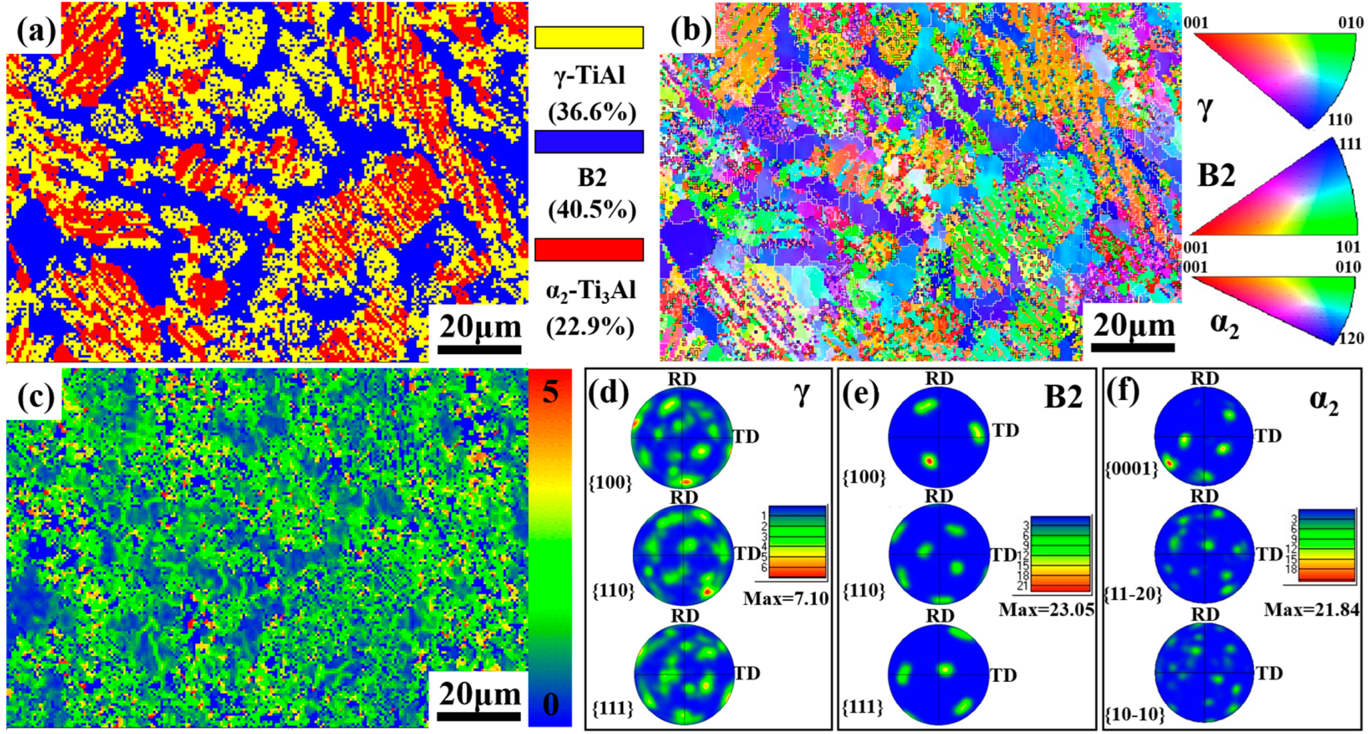
3.1. Initial Microstructure

Figure 1 shows the initial microstructure of the as-forged β-γ TiAl alloy. As shown in the phase map (Figure 1a), the as-forged alloy has a refined microstructure consisting of γ grains (yellow), B2 phase (blue) and residual lamellar colonies with a size of about 20 µm consisting of γ (yellow) and α2 (red) phases. Figure 1b shows the inverse pole figure (IPF) maps overlaid with low-angle grain boundaries (LAGB, 2~15°, white lines) and high-angle grain boundaries (HAGB, >15°, black lines). Clearly, the forged microstructure has a dominant distribution of LAGBs. Interestingly, the HAGBs mainly distribute around B2 phases regions, while the LAGBs prefer to distribute in the γ phases regions. The local misorientation map is illustrated in Figure 1c, where blue color indicates the low misorientation region and red color indicates the high misorientation region. It can be observed that the areas with a high degree of misorientation are mainly present in the γ phase and lamellar colonies regions. The finding suggests that these regions underwent severe deformation during forging, leading to a high level of residual strain [15]. The B2 exhibits preferred orientation in (111) direction, as confirmed by Figure 1d–f. That is because bcc B2 phases are soft phases at high temperature, which exhibit more independent slip systems and more easily deform [26]. Further, the preferred orientation may originate from highly symmetrical multi-slip of B2 phases during isothermal forging. In addition, the preferred orientation of B2 phases still was in (111) direction after hot compression based on Ref. [27]. The uniform microstructure results from the 3D isothermal forging. Moreover, the obtained duplex microstructure is because the deformation temperature is located at the α + γ phase region, and γ lamella precipitated from α phase and partly α phase translated to α2 lamella during cooling, forming a lamellar microstructure (α2 + γ). A similar microstructure can be observed in the high Nb-TiAl alloy and TNM alloys, which transforms to a fully lamellar microstructure after heat treatment in the single α phase region.

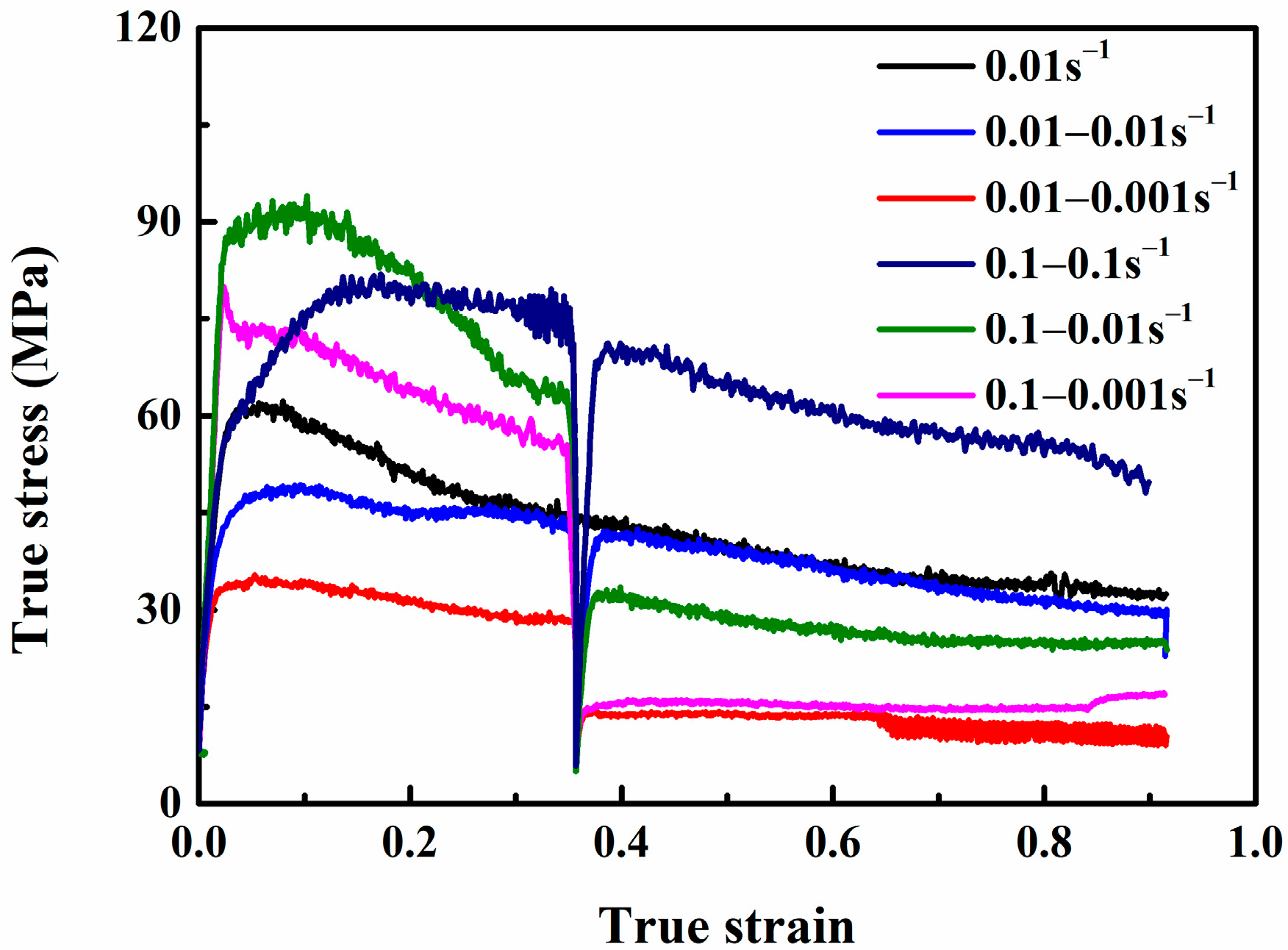
3.2. True Stress–Strain Curves

In Figure 2, the true stress–strain curves of the forged β-γ TiAl alloy are presented without any smoothing technique applied to the original data. Hot deformation was performed in variable conditions at 1200 °C under variable strain rates, up to an engineering strain of ε = 0.6. The flow curves showed typical DRX softening feature during continuous deformation, which was consistent with previous studies [3,13]. The flow stress was lower compared with TNM alloy under the same deformation condition, which was attributed to the refined microstructure consisting of γ grains, B2 phase and residual lamellar colonies with a size of about 20 µm. The flow curves with discontinuous deformation exhibit a characteristic “single-peak” flow behavior, where the flow stress rapidly rises to the peak after work hardening caused by dislocation multiplication and accumulation during the first stage (ε < 0.1). Subsequently, the flow stress reaches a steady state as DRX occurs [15,26]. After holding for 30 s at ε = 0.3, a sudden decrease in strain rate results in an abrupt drop in stress to a new level. Conversely, maintaining the same strain rate for 30 s at ε = 0.3 leads to no significant change in stress levels, indicating that the flow stress is significantly affected by strain rate. The corresponding deformation mechanism will be discussed though the deformation microstructure analysis below.

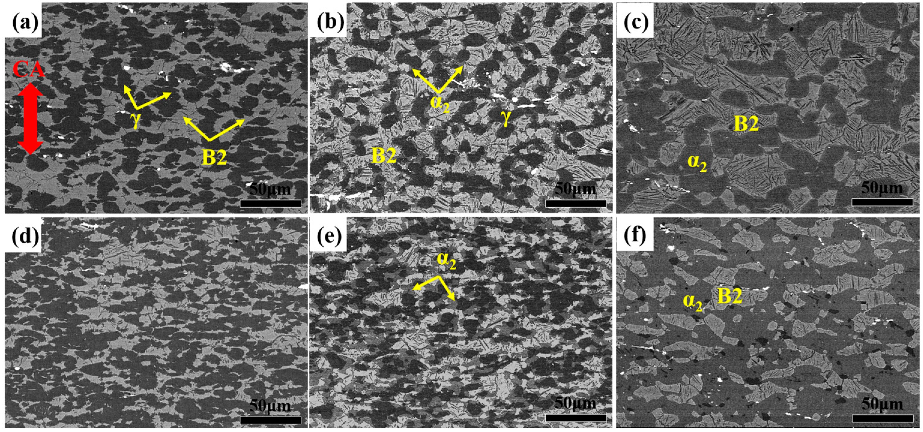
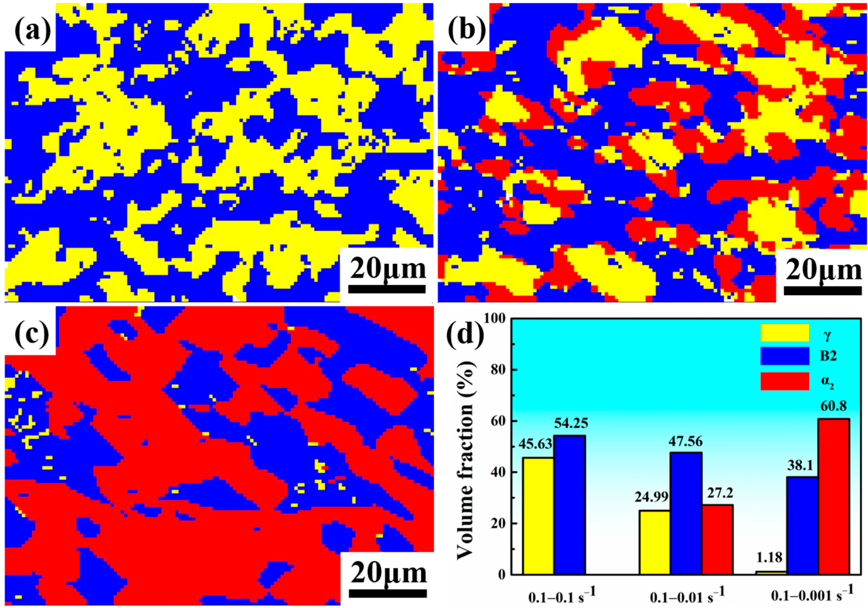
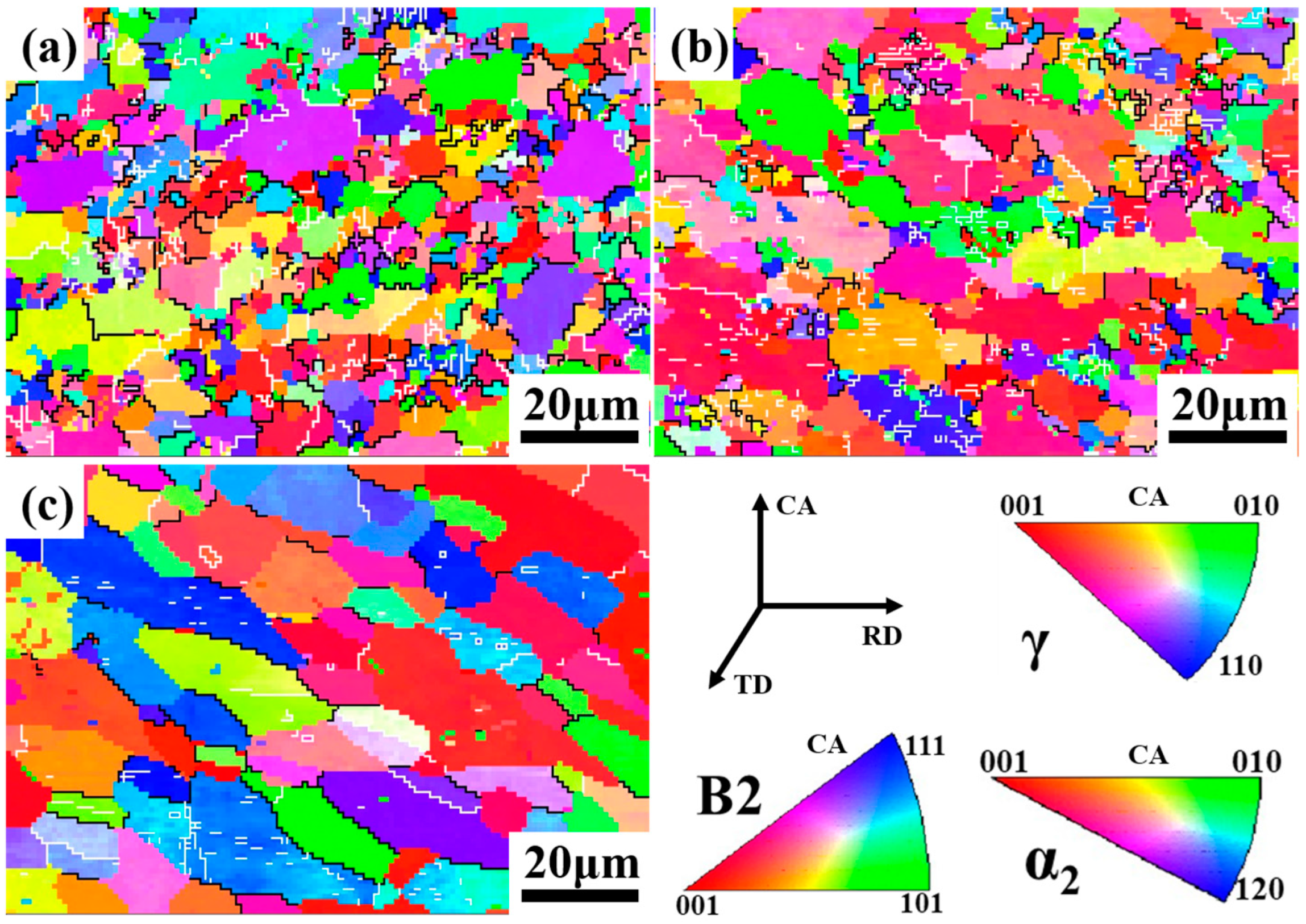
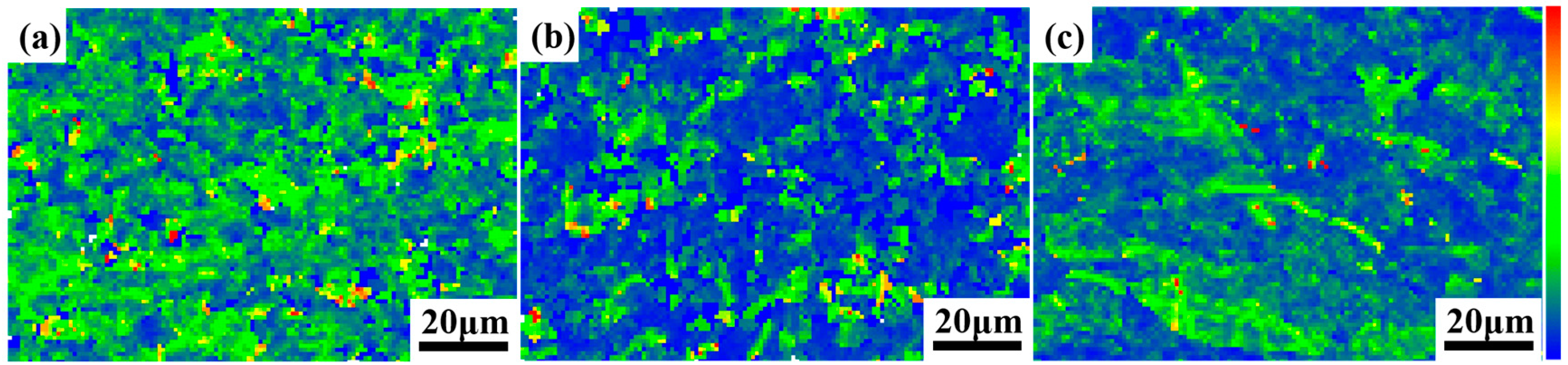
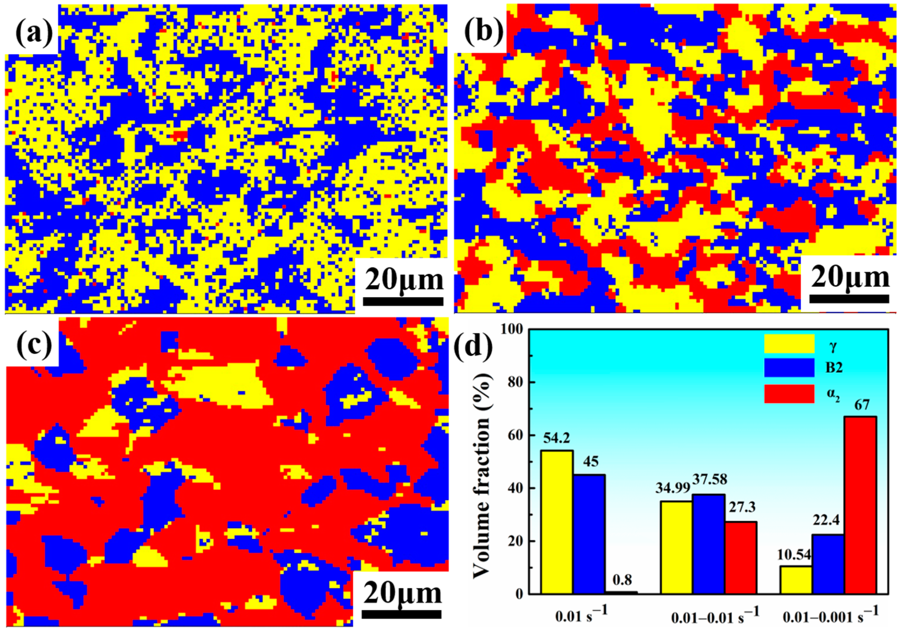
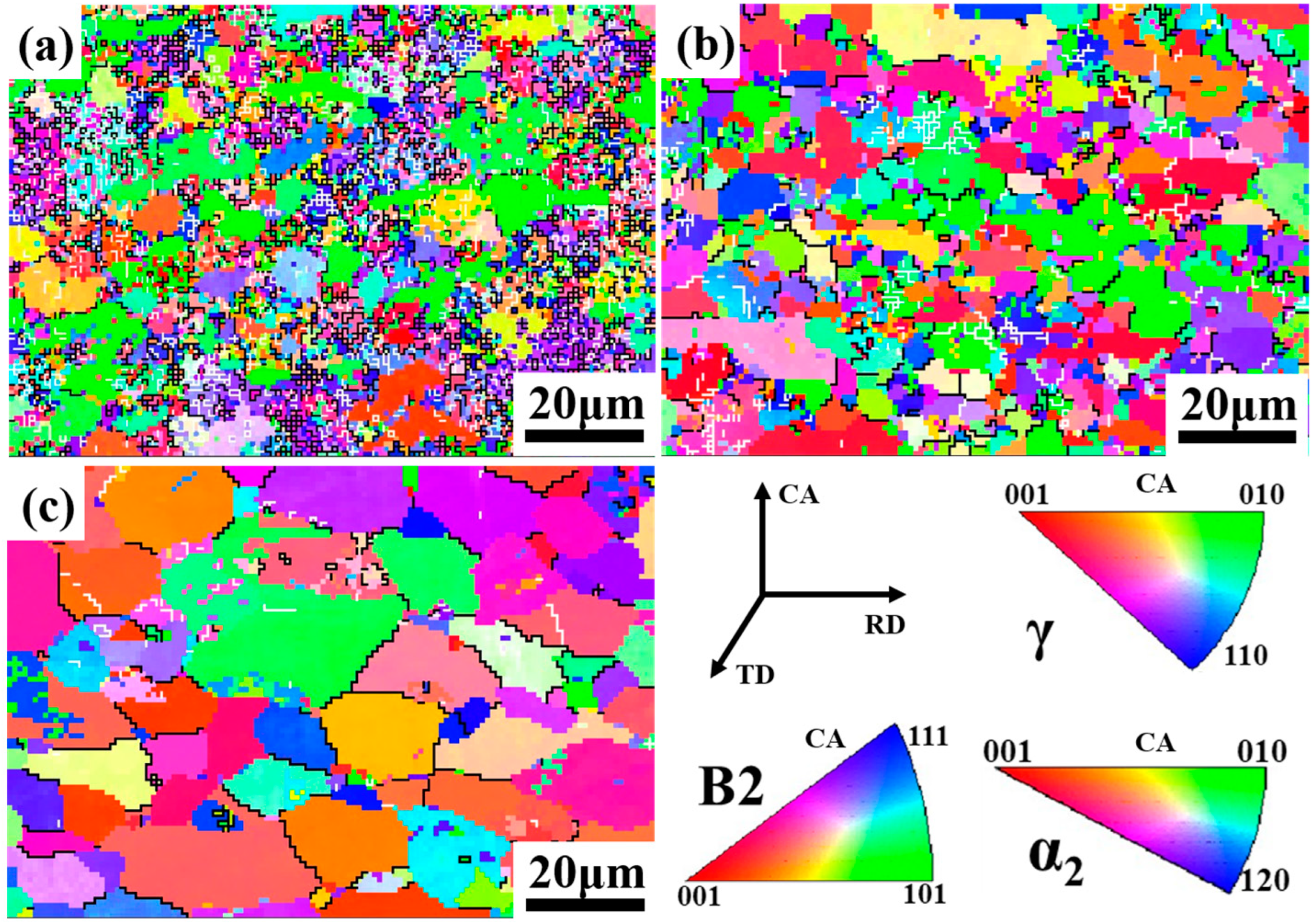
3.3. Deformed Microstructures

Figure 3 displays the deformed microstructures of the β-γ TiAl alloy under different variable hot deformation conditions. The deformed microstructure is composed of equiaxed grains without residual lamellae, indicating sufficient DRX. Notably, Figure 3a,d shows pure equiaxed γ (black) and B2 (bright) grains without α2 phase (gray) detected at a high strain rate and continuous medium strain rates. At the initial structure of the test material, α2 phases mainly existed in lamellar microstructure. During hot compression, DRX preferentially occurred at lamellar grain boundaries due to the high stress concentration caused by the hard deformation orientation [27]. As a result, the lamellar colonies decomposed (L→γ + β) by DRX after compression at 1200 °C, which is also reported in Refs. [27,28,29,30]. In addition, the γ→α PT was insufficient due to the short time caused by high strain rate, resulting in the formation of pure equiaxed γ and B2 grains without α2 phase. Conversely, a mixture of γ + B2/β + α2 microstructure can be obtained through the two-step hot deformation at a sudden decrease to low strain rates, as shown in Figure 3b,c,e,f. This suggests that phase transformation (PT) occurs during the deformation process. Details on this will be discussed later. Furthermore, it can be observed that DRX grain growth is significant at lower strain rates, in which sufficient deformation time is provided to enable the growth of DRX grains. Moreover, bright particles were observed in all the samples, which was deduced to be rare earth oxide based on previous study. Moreover, the rare earth oxide was broken during isothermal forging and hot compression. The rare earth oxide inhabited the dislocation motion and promoted DRX.
The EBSD analysis in Figure 4, Figure 5, Figure 6, Figure 7, Figure 8 and Figure 9 provides further insight into the deformed microstructures of the studied β-γ TiAl alloy. Figure 4 illustrates the phase map and the corresponding volume fraction after the variable conditions (i). The deformed microstructure is composed of γ, α2 and B2 grains without residual lamellar colonies, indicating that DRX has occurred sufficiently. The phase content changes significantly after deformation under fast strain rate (0.1–0.1 s−1), with the γ and B2-DRX occurring simultaneously at the lamellar grain boundaries ((L→γ + β)) when the DRX driving force caused by stress concentration reaches a critical value at a deformation temperature of 1200 °C [13], and the duplex deformed microstructure without α2 phases that was obtained due to short deformation time resulted in few γ→α PT. However, the γ→α PT is promoted by stress concentration and more deformation time during the two-step deformation in the case of variable low strain rate, causing a significant change in the phase composition of the deformed microstructure. Specifically, the content of α2 phase increases rapidly as the strain rate suddenly decreases at ε = 0.3, while the content of γ phase decreases. This transformation from γ to α phase is shown in Figure 4a–c, with the volume fraction of α2 phase increasing from 0% to 60.8% as the strain rate drops from 0.1 to 0.001 s−1 at ε = 0.3. Conversely, the volume fraction of γ phase decreases from 45.63% to 1.18% (Figure 4d). Notably, the content of B2 does not change significantly after deformation, likely because it is softer at elevated temperatures and serves as a coordinating element during deformation [31].
In Figure 5, the IPF maps show the deformed microstructure under variable conditions (i) overlaid with grain boundaries. Figure 5a presents a non-uniform deformed microstructure containing equiaxed grains. Meanwhile, it can be found that the DRX grains have undergone significant growth and elongation when the strain rate is abruptly decreased at ε = 0.3, as exhibited in Figure 5b,c. The change in the deformed microstructure is mainly attributed to the increased deformation time provided by the low strain rate, leading to the growth and elongation of DRX grain. In addition, the grains are assigned a variety of colors, indicating no significant texture component in the deformed microstructure, as presented in Figure 5. The orientations are randomly distributed, suggesting that the deformed microstructure is isotropic and sufficient DRX has occurred under the present experiment’s deformation conditions. In addition, the deformed microstructure showed a prevalence of HAGBs predominantly located in the DRX region, whereas the substructure area demonstrated a greater preference for LAGBs [18,20]. The consumption of deformed and sub-structured grains leads to DRX and grain growth, resulting in the evolution of LAGBs into HAGBs [32].
The variations in deformation microstructure can be characterized by the local misorientation distributions. These distributions can also be used to represent geometric dislocation densities (GNDs) and evaluate the degree of DRX. Higher local misorientation values indicate higher dislocation densities or strain, while lower values suggest the opposite. Local misorientation can be used to evaluate the degree of DRX as a decrease in dislocation density is observed with increasing DRX. Figure 6 displays the local misorientation map of a deformed microstructure under variable conditions (i). From Figure 6a–c, it is evident that the local misorientation decreases significantly when the strain rate abruptly drops after being held at ε = 0.3 for 30 s. This is an indication that residual stresses are eliminated by PT and DRX. The region of low misorientation is primarily located around the B2 phases region under high strain rate, while high misorientation is found in the γ phases region, suggesting that the γ phase experienced significant deformation, resulting in higher residual strain [19]. However, when holding at ε = 0.3 and suddenly decreasing the strain rate, γ→α PT is promoted, leading to the partial consumption of dislocations and a subsequent decrease in local misorientation values, as shown in Figure 6b,c. Notably, lower local misorientation values are mostly located in regions of α2 where γ→α PT and α grain growth occurs. This finding suggests that changing the strain rate during hot deformation eliminated the residual strain.
After undergoing the variable conditions (ii) and (iii), the deformed microstructure is analyzed and the phase maps are presented in Figure 7. The analysis revealed significant changes in the phase composition when the material was deformed at a strain rate of 0.01 s−1 to ε = 0.3, holding 30 s, and then continuation of strain rate with 0.01 and 0.001 s−1, respectively. Notably, the content of α2 phase was only 0.8% under constant deformation (Figure 7a), but its content increased rapidly as strain rate decreased at the second step. This indicates that the low strain rate provides more deformation time for γ phases transformed into α phases, which grew perpendicularly to the compressive axial, as illustrated in Figure 7b,c.
In Figure 8, the IPF maps of tested materials deformed at variable conditions (ii) and (iii) are presented. Equiaxed grains dominate the deformed microstructure at constant 0.01 s−1 to ε = 0.6 and a strain rate of 0.01 s−1 to ε = 0.3 held for 30 s and then continue deformation in strain rate to 0.01 s−1, with a few grains growing abnormally, as shown in Figure 8a,b. However, at a strain rate of 0.01 s−1 to ε = 0.3 held for 30 s, then subjected to an abrupt change in strain rate to 0.001 s−1, the DRX grains experience significant growth and elongation, as depicted in Figure 8c. The current findings demonstrate that the DRX is adequate, and the growth of DRX grains and γ→α PT take place in distinct deformed microstructures. Furthermore, it was observed that HAGBs were primarily located in the DRX area, while LAGBs were mostly distributed in the substructure area, which corresponds with the variable conditions (i).
In Figure 9, the local misorientation map of studied β-γ TiAl alloy deformed under variable conditions (ii) is depicted. The microstructure that was deformed at a constant strain rate demonstrates a higher degree of local misorientation compared to the microstructure that was deformed at variable strain rates. This implies that the former microstructure contains more residual strain [33,34]. The stress concentration is generated during deformation due to the poor plastic deformation of TiAl alloys, which could not be released quickly under the constant deformation condition, leading to a higher local misorientation in the deformed microstructure [32]. Figure 9c displays that a high level of local misorientation is observed when the strain rate decreases to 0.001 s−1 at ε = 0.3. This observation denotes that the α phase with large size is deformed under low deformation strain rates.
According to the present findings, during the high strain rate and continuous medium strain rate deformation process, the deformed microstructure comprises γ and B2 phases. Notably, α2 phase was not detected by EBSD, which is likely due to the time needed for the first deformation simply being too short for γ to α transformation. Residual stress is evident after deformation due to dislocation pile-up and insufficient DRX under high strain rate [35]. When the deformation was carried out at 1200 °C (γ + β + α2) in the case of variable high strain rate and continuous medium strain rate deformation (0.1–0.1 s−1, 0.01 s−1), the lamellar colonies were bent and elongated at the initial stage, and then the γ-DRX and β-DRX preferentially occurred at the lamellar grain boundaries. The lamellar colonies phase transition (L→γ + β) decomposition was significant upon increasing the strain (ε < 0.3). The γ to α transformation was insufficient due to the high strain rate, resulting in the short deformation time, and the high strain rate was also detrimental to the α-DRX. Therefore, the duplex microstructure containing γ + B2/β was obtained after deformation at variable high strain rate and continuous medium strain rate, which adversely affects the hot workability of the TiAl alloy. However, sufficient time was provided by discontinuous two-step deformation at low strain rate (0.1–0.01 s−1 and 0.01–0.01 s−1), and the stress concentration caused by the first step of deformation also promoted the γ→α PT, which all resulted in an increase in the α phase content. This increase is dependent on the strain rate change at ε = 0.3. Consequently, uniform mixtures of γ + B2/β + α2 microstructure can be observed after performing two-step hot deformation with a deformation rate of 0.1–0.01 s−1 and 0.01–0.01 s−1, as demonstrated in Figure 4 and Figure 7. During the lower strain rate deformation process (0.1–0.001 s−1 and 0.01–0.001 s−1), there is abnormal grain growth of the α phase, leading to a non-uniform deformed structure. This is attributed to the low strain rates providing enough time for the γ→α PT and DRX grain growth. Refs. [13,36] report that excellent hot workability can be achieved by preparing uniform and fine γ + B2/β + α2 microstructures without abnormal grain growth and lamellar colonies. These findings suggest that adjusting the appropriate strain rates under two-step hot deformation can enhance the hot workability of the β-γ TiAl alloy.

4. Conclusions

A comprehensive investigation was conducted on the flow stress and microstructure evolution of forged β-γ TiAl alloy under variable strain rates during two-step hot deformation. The key findings are outlined as follows:
  • The true stress–strain curves of the forged β-γ TiAl alloy composed of a mixture of refined γ phase, B2 grains and lamellar colonies were highly dependent on strain rate. The stress level experienced an abrupt drop when the strain rate was suddenly reduced at ε = 0.3 after holding for 30 s due to the lower strain rate, leading to more sufficient DRX.
  • The γ + B2/β microstructure without α2 phase was achieved when variable high strain rate and continuous medium strain rate were applied, which resulted from the hot deformation time that was simply too short for γ→α PT. However, during the two-step hot deformation process in the case of low strain rate, more deformation time was provided and the stress concentration also promoted γ→α PT, resulting in a significant increase in the α content at 1200 °C.
  • By decreasing the strain rate after the first stage, a fine-grained γ + B2/β + α2 microstructure with less residual stress and more sufficient DRX can be achieved, which is mainly attributed to the appropriate strain rate and stress concentration that partly promoted γ→α PT, leading to the γ + B2/β + α formed at 1200 °C.
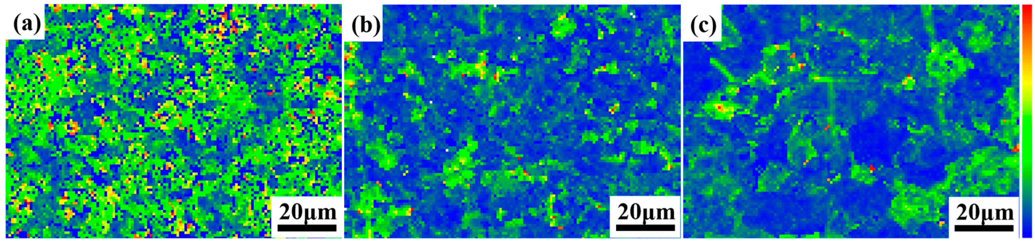
  • Both the γ→α PT and DRX grain growth promoted deformability and reduced dislocation pile-up during the two-step hot deformation, resulting in a significant reduction in the deformation residual stress and local misorientation density. This improvement in microstructure can significantly enhance the hot workability of β-γ TiAl alloys.

Author Contributions

Conceptualization, T.M.; methodology, Z.C.; writing—original draft preparation, G.L. and Y.W.; writing—review and editing, Y.W., Z.C., Q.X., X.Z. (Xinzhe Zhang), X.Z. (Xinfang Zhang) and C.Y.; Resources, Z.C. and G.L. All authors have read and agreed to the published version of the manuscript.

Funding

This work was supported by the National Natural Science Foundation of China (No. 52001262, 52001283), Key Technologies Research and Development Program of Henan Province of China (No. 212102210447, 222102230041, 212102210109) and National Key Laboratory Foundation of Science and Technology on Materials under Shock and Impact (No. 6142902220202).

Data Availability Statement

Not applicable.

Conflicts of Interest

The authors declare no conflict of interest.

References

  1. Ding, J.; Zhang, M.H.; Liang, Y.F.; Ren, Y.; Dong, C.L.; Lin, J.P. Enhanced high-temperature tensile property by gradient twin structure of duplex high-Nb-containing TiAl alloy. Acta Mater. 2018, 161, 1–11. [Google Scholar] [CrossRef]
  2. Ma, T.F.; Li, Q.Y.; Wang, Y.P.; Wang, X.H.; Dong, D.; Zhu, D.D. Microstructure and mechanical properties of micro-nano Ti2AlC-reinforced TiAl composites. Intermetallics 2022, 146, 107563. [Google Scholar] [CrossRef]
  3. Chen, R.R.; Ma, T.F.; Guo, J.J.; Ding, H.S.; Su, Y.Q.; Fu, H.Z. Deformation behavior and microstructural evolution of hydrogenated Ti44Al6Nb alloy during thermo-compression at 1373–1523 K. Mater. Des. 2016, 108, 259–268. [Google Scholar] [CrossRef]
  4. Yang, J.R.; Chen, R.R.; Su, Y.Q.; Ding, H.S.; Guo, J.J.; Fu, H.Z. Optimization of electromagnetic energy in cold crucible used for directional solidification of TiAl alloy. Energy 2018, 161, 143–155. [Google Scholar] [CrossRef]
  5. Liu, C.Z.; Wang, Y.P.; Han, W.Z.; Ma, T.F.; Ma, D.F.; Zhang, Y.S. Achieving Superior High-Temperature Strength and Oxidation Resistance of TiAl Nanocomposite through In Situ Semicoherent MAX Phase Precipitation. ACS Appl. Mater. Interfaces 2022, 14, 8394–8403. [Google Scholar] [CrossRef] [PubMed]
  6. Xu, R.R.; Li, M.Q.; Zhao, Y.H. A review of microstructure control and mechanical performance optimization of γ-TiAl alloys. J. Alloys Compd. 2023, 932, 167611. [Google Scholar] [CrossRef]
  7. Peng, P.; Zhou, S.D.; Liu, Z.J.; Pei, X.; Gan, L.; Xu, Y.L.; Zhang, X.D.; Ma, Z.K.; Wang, J.T. Analysis on microstructure and mechanical properties of Ti-47.5Al-3Nb-1.5Cr alloy through heat-treatment. J. Alloys Compd. 2022, 908, 164689. [Google Scholar] [CrossRef]
  8. Li, X.B.; Xu, H.; Xing, W.W.; Chen, B.; Shu, L.; Zhang, M.S.; Liu, K. Microstructural evolution and mechanical properties of forged β-solidified γ-TiAl alloy by different heat treatments. Trans. Nonferrous Met. Soc. China 2022, 32, 2229–2242. [Google Scholar] [CrossRef]
  9. Clemens, H.; Mayer, S. Design, Processing, Microstructure, Properties, and Applications of Advanced Intermetallic TiAl Alloys. Adv. Eng. Mater. 2013, 15, 191–215. [Google Scholar] [CrossRef]
  10. Liang, Z.Q.; Xiao, S.L.; Li, Q.C.; Yu, H.B.; Zheng, Y.F.; Xu, L.J.; Xue, X.; Tian, J.; Chen, Y.Y. Tensile creep behavior of a heat treated β-solidified γ-TiAl alloy: The development of dynamic recrystallization and the role of B2 phase. Mater. Sci. Eng. A 2023, 863, 144522. [Google Scholar] [CrossRef]
  11. Bernal, D.; Chamorro, X.; Hurtado, I.; Madariag, I. Evolution of lamellar microstructures in a cast TNM alloy modified with boron through single-step heat treatments. Intermetallics 2020, 124, 106842. [Google Scholar] [CrossRef]
  12. Ma, T.F.; Li, S.Y.; Wang, Y.P.; Wang, X.H.; Dong, D.; Zhu, D.D. Phase transformation and dynamic recrystallization behavior of forged beta gamma TiAl alloy in variable thermomechanical conditions. J. Mater. Res. Technol. 2022, 18, 4796–4803. [Google Scholar] [CrossRef]
  13. Ge, G.W.; Zhang, L.Q.; Xin, J.J.; Lin, J.P.; Aindow, M.; Zhang, L.C. Constitutive modeling of high temperature flow behavior in a Ti-45Al-8Nb-2Cr-2Mn-0.2Y alloy. Sci. Rep. 2018, 8, 5453. [Google Scholar] [CrossRef] [PubMed]
  14. Lapin, J.; Pelachová, T.; Bajana, O. High temperature deformation behaviour and microstructure of cast in-situ TiAl matrix composite reinforced with carbide particles. J. Alloys Compd. 2019, 797, 754–765. [Google Scholar] [CrossRef]
  15. Ma, T.F.; Chen, R.R.; Zheng, D.S.; Guo, J.J.; Ding, H.S.; Su, Y.Q.; Fu, H.Z. Hydrogen-induced softening of Ti-44Al-6Nb-1Cr-2V alloy during hot deformation. Int. J. Hydrogen Energy 2017, 42, 8329–8337. [Google Scholar] [CrossRef]
  16. Lin, X.J.; Huang, H.J.; Yuan, X.G.; Wang, Y.X.; Zheng, B.W.; Zuo, X.J.; Zhou, G. Study on hot deformation behavior and processing map of a Ti-47.5Al-2.5V-1.0Cr-0.2Zr alloy with a fully lamellar microstructure. J. Alloys Compd. 2022, 901, 163648. [Google Scholar] [CrossRef]
  17. Ye, P.H.; Jin, X.C.; Fang, W.B.; Li, X.W.; Wu, H.; Fan, G.H. Hot deformation behavior and microstructure evolution of a high Nb containing PM TiAl composite reinforced with Ti2AlC particles. Mater. Today Commun. 2021, 29, 102862. [Google Scholar] [CrossRef]
  18. Xu, R.R.; Li, H.; Li, M.Q. Flow softening mechanism in isothermal compression of β-solidifying γ-TiAl alloy. Mater. Des. 2020, 186, 108328. [Google Scholar] [CrossRef]
  19. Lapin, J.; Štamborská, M.; Pelachov, T.; Čegan, T.; Volodarskaja, A. Hot deformation behaviour and microstructure evolution of TiAl-based alloy reinforced with carbide particles. Intermetallics 2020, 127, 106962. [Google Scholar] [CrossRef]
  20. Chen, X.F.; Tang, B.; Liu, Y.; Xue, X.Y.; Li, L.; Kou, H.C.; Li, J.S. Dynamic recrystallization behavior of the Ti–48Al–2Cr–2Nb alloy during isothermal hot deformation. Prog. Nat. Sci.-Mater. 2019, 29, 587–594. [Google Scholar] [CrossRef]
  21. Yu, Q.Y.; Yao, Z.H.; Dong, J.X. Deformation and recrystallization behavior of a coarse-grain, nickel-base superalloy Udimet 720Li ingot material. Mater. Charact. 2015, 107, 398–410. [Google Scholar] [CrossRef]
  22. Liu, D.H.; Chai, H.R.; Yang, L.; Qiu, W.Q.; Guo, Z.H.; Wang, Z.L. Study on the dynamic recrystallization mechanisms of GH5188 superalloy during hot compression deformation. J. Alloys Compd. 2022, 895, 162565. [Google Scholar] [CrossRef]
  23. Jiang, W.X.; Lu, J.X.; Guan, H.; Wang, M.M.; Cheng, X.P.; Lin, L.L.; Liu, X.Q.; Wang, J.; Zhang, Y.F.; Zhang, Z.; et al. Study of pre-precipitated δ phase promoting deformation twinning and recrystallization behavior of Inconel 718 superalloy during hot compression. Mater. Des. 2023, 226, 111693. [Google Scholar] [CrossRef]
  24. Wan, Z.; Sun, Y.; Hu, L. Dynamic softening behavior and microstructural characterization of TiAl-based alloy during hot deformation. Mater. Charact. 2017, 130, 25–32. [Google Scholar] [CrossRef]
  25. Huang, K.; Logé, R.E. Microstructure and flow stress evolution during hot deformation of 304L austenitic stainless steel in variable thermomechanical conditions. Mater. Sci. Eng. A 2018, 711, 600–610. [Google Scholar] [CrossRef]
  26. Wang, Q.; Chen, R.R.; Yang, Y.H.; Wu, S.W.; Guo, J.J.; Ding, H.S.; Su, Y.Q.; Fu, H.Z. Effects of lamellar spacing on microstructural stability and creep properties in β-solidifying γ-TiAl alloy by directional solidification. Mater. Sci. Eng. A 2018, 711, 508–514. [Google Scholar] [CrossRef]
  27. Tang, B.; Wang, W.Y.; Xiang, L.; Liu, Y.; Zhu, L.; Ji, S.J.; He, J.; Li, J.S. Metadynamic recrystallization behavior of β-solidified TiAl alloy during post-annealing after hot deformation. Intermetallics 2020, 117, 106679. [Google Scholar] [CrossRef]
  28. Jiang, H.T.; Zeng, S.W.; Zhao, A.M.; Ding, X.N.; Dong, P. Hot deformation behavior of β phase containing γ-TiAl alloy. Mater. Sci. Eng. A 2016, 661, 160–167. [Google Scholar] [CrossRef]
  29. Stendal, J.A.; Eisentraut, M.; Imran, M.; Sizova, I.; Bolz, S.; Weib, S.; Bambach, M. Accelerated hot deformation and heat treatment of the TiAl alloy TNM-B1 for enhanced hot workability and controlled damage. J. Mater. Process. Technol. 2021, 291, 116999. [Google Scholar] [CrossRef]
  30. Cui, N.; Kong, F.T.; Wang, X.P.; Chen, Y.Y.; Zhou, H.T. Hot deformation behavior and dynamic recrystallization of a β-solidifying TiAl alloy. Mater. Sci. Eng. A 2016, 652, 231–238. [Google Scholar] [CrossRef]
  31. Liu, Y.; Li, J.S.; Tang, B.; Song, L.; Wang, W.Y.; Liu, D.; Yang, R.; Kou, H.C. Decomposition and phase transformation mechanisms of α2 lamellae in β-solidified γ-TiAl alloys. Acta Mater. 2022, 242, 118492. [Google Scholar] [CrossRef]
  32. Tian, S.W.; Jiang, H.T.; Guo, W.Q.; Zhang, G.H.; Zeng, S.W. Hot deformation and dynamic recrystallization behavior of TiAl-based alloy. Intermetallics 2019, 112, 106521. [Google Scholar] [CrossRef]
  33. Hughes, D.A.; Hansen, N.; Bammann, D.J. Geometrically necessary boundaries, incidental dislocation boundaries and geometrically necessary dislocations. Scr. Mater. 2003, 48, 147–153. [Google Scholar] [CrossRef]
  34. Wang, Q.B.; Zhang, S.Z.; Zhang, C.J.; Zhang, W.G.; Yang, J.R.; Duo, D.; Zhu, D.D. The influence of the dynamic softening mechanism of α phase and γ phase on remnant lamellae during hot deformation. J. Alloys Compd. 2021, 872, 159514. [Google Scholar] [CrossRef]
  35. Zhou, H.T.; Kong, F.T.; Wu, K.; Wang, X.P.; Chen, Y.Y. Hot pack rolling nearly lamellar Ti-44Al-8Nb-(W, B, Y) alloy with different rolling reductions: Lamellar colonies evolution and tensile properties. Mater. Des. 2017, 121, 202–212. [Google Scholar] [CrossRef]
  36. Niu, H.Z.; Chen, Y.F.; Zhang, Y.S.; Lu, J.W.; Zhang, W.; Zhang, P.X. Phase transformation and dynamic recrystallization behavior of a β-solidifying γ-TiAl alloy and its wrought microstructure control. Mater. Des. 2016, 90, 196–203. [Google Scholar] [CrossRef]
Figure 1. Initial microstructures of the forged β-γ TiAl alloy: (a) phase map; (b) IPF map with grain boundaries; (c) local misorientation map; (df) PF of the γ, B2 and α2 phases (the TD was perpendicular to the CA in the PF).
Crystals 13 00742 g001
Figure 2. True stress–strain curves of the forged β-γ TiAl alloy in variable conditions.
Crystals 13 00742 g002
Figure 3. SEM-BSE images of deformed microstructure for the forged β-γ TiAl alloy in variable conditions: (a) 0.1–0.1 s−1; (b) 0.1–0.01 s−1; (c) 0.1–0.001 s−1; (d) 0.01 s−1; (e) 0.01–0.01 s−1 and (f) 0.01–0.001 s−1.
Crystals 13 00742 g003
Figure 4. Phase distribution map of deformed microstructure at ε = 0.3 holding 30 s sudden change strain rate and then continuing to deform to ε = 0.6: (a) 0.1–0.1 s−1; (b) 0.1–0.01 s−1; (c) 0.1–0.001 s−1 and (d) the corresponding volume fraction of the phases.
Crystals 13 00742 g004
Figure 5. IPF maps with grain boundaries (LAGB, 2~15°, white lines; HAGB, >15°, black lines) of microstructure deformed at ε = 0.3 holding 30 s sudden change strain rate and then continuing to deform to ε = 0.6: (a) 0.1–0.1 s−1; (b) 0.1–0.01 s−1; (c) 0.1–0.001 s−1.
Crystals 13 00742 g005
Figure 6. Local misorientation maps of deformed microstructure at ε = 0.3 holding 30 s sudden change strain rate and then continuing to deform to ε = 0.6: (a) 0.1–0.1 s−1; (b) 0.1–0.01 s−1; (c) 0.1–0.001 s−1.
Crystals 13 00742 g006
Figure 7. Phase distribution maps of deformed microstructure under constant 0.01 s−1 and at ε = 0.3 holding 30 s sudden change strain rate and then continuing to deform to ε = 0.6: (a) 0.01 s−1; (b) 0.01–0.01 s−1; (c) 0.01–0.001 s−1 and (d) the corresponding volume fraction of phases.
Crystals 13 00742 g007
Figure 8. IPF maps with grain boundaries (LAGB, 2~15°, white lines; HAGB, >15°, black lines) of deformed microstructure under constant 0.01 s−1 and at ε = 0.3 holding 30 s sudden change strain rate and then continuing to deform to ε = 0.6: (a) 0.01 s−1; (b) 0.01–0.01 s−1; (c) 0.01–0.001 s−1.
Crystals 13 00742 g008
Figure 9. Local misorientation map of deformed microstructure under constant 0.01 s−1 and at ε = 0.3 holding 30 s sudden change strain rate and then continuing to deform to ε = 0.6: (a) 0.01 s−1; (b) 0.01–0.01 s−1; (c) 0.01–0.001 s−1.
Crystals 13 00742 g009
Disclaimer/Publisher’s Note: The statements, opinions and data contained in all publications are solely those of the individual author(s) and contributor(s) and not of MDPI and/or the editor(s). MDPI and/or the editor(s) disclaim responsibility for any injury to people or property resulting from any ideas, methods, instructions or products referred to in the content.

