Article

Crystal Structure and Properties of Zinc Phosphate Layers on Aluminum and Steel Alloy Surfaces

1
BPW-Hungária Ltd., 9700 Szombathely, Hungary
2
Department of Materials Engineering, Faculty of Engineering, University of Pannonia, 8201 Veszprém, Hungary
*
Author to whom correspondence should be addressed.
Crystals 2023, 13(3), 369; https://doi.org/10.3390/cryst13030369
Submission received: 30 January 2023 / Revised: 14 February 2023 / Accepted: 19 February 2023 / Published: 21 February 2023

Abstract

:
Many studies have been carried out on the phosphating of steel and aluminum alloys used in automotive engineering, but characterization of the properties of the phosphate layers formed by the co-phosphating of these alloys in the presence of different base metals is still lacking. In this study, the crystal structure and properties of the phosphate conversion layers formed on the surface of the aluminum alloys important in vehicle manufacturing (cast and forged AlSi1MgMn, and AA6014 panel) and the CRS SAE 1008/1010 reference steel plate by co-deposition prior to painting were investigated. On a process line set up for the phosphating of typical iron and steel alloys, the phosphate coating was formed using nitrite and nitroguanidine accelerators under identical technological parameters. The microstructure of the formed phosphate layers was examined using scanning electron microscopy (SEM), its phase composition using X-ray diffraction (XRD), and its elemental composition using energy-dispersive X-ray analysis (EDX). The suggested main crystalline phase (Zn2.3(Ni0.1Mn0.6)(PO4)2·4H2O) in the surface phosphate layer of both aluminum alloys studied was similar to hopeite, whereas in the steel plate, a minor hopeite phase were identified in addition to the main crystalline phosphophyllite phase (~95%). It can be concluded that, during the combined phosphating treatments, the surfaces of different aluminum and steel alloys behaved similarly to the individual treatments and did not impede the coating reactions of the other metal. To obtain an adequate coating of aluminum and steel alloys, fluoride should always be present in the production line. Comparing the effects of accelerators, we found that the use of nitrite accelerator with the same amount of fluoride resulted in a higher coverage and better quality of the surface protective layer of the aluminum alloys. However, for the steel plate, there was no significant difference between the phosphate coatings prepared with the two different accelerators.

1. Introduction

In the automotive industry, particularly in agricultural and road vehicle manufacturing, corrosion-resistant multi-layer coatings that encounter metal usually have a phosphating layer at the bottom layer. This adheres tightly to the underlying metal, protecting the base metal from corrosion and improving the correct adhesion of the paints and organic finishes to be applied subsequently [1,2]. For vehicle manufacturing applications, this layer is usually zinc phosphate as it provides the best corrosion protection in outdoor and extreme (salty, wet, marine) conditions [2,3,4,5].
Complex agricultural vehicle bodies usually contain a phosphate layer with a varying composition and microstructure on the surface of the raw materials, depending on their physical and chemical properties. This affects the corrosion protection properties of the final coating [6]. Vehicle manufacturers assemble parts of complex design from various base metals, such as aluminum and steel alloys, that undergo different machining stages (welding, machining, sheet metalworking, forging, etc.) and mechanical pre-treatments [1,3]. Therefore, a process of pre-treatment before painting must be developed to ensure that the coating systems formed by the multi-metal treatments meet corrosion resistance requirements [3]. Zinc phosphate coatings on metal surfaces are very often the first layer of multi-layer corrosion protection coating and are expected to uniformly cover the base metal surface, thereby protecting the base metal from corrosion effects in the event of damage to the corrosion protection coating. This zinc phosphate layer is also intended to ensure proper adhesion of the applied paint layer [2]. On the other hand, phosphate coatings on the zinc surfaces, e.g., on the hot-dip galvanized or electrogalvanized zinc surface of the car body, must not only provide excellent corrosion resistance but also ensure good paintability and good adhesion of the paint layer [7,8,9,10]. During surface protection by phosphating, a phosphate layer consisting of crystals and/or mixed crystals containing iron, zinc, and manganese is formed on the metal surface, depending on the composition of the phosphating solution [6]. The quality of the base metal, the method of surface pretreatment, and the technological and operational conditions of the phosphating process (composition of baths, addition of metals to the modified phosphating bath, temperature, treatment time, pH, acceleration, etc.) influence the formation and structure of the phosphate layer [11,12,13,14,15,16,17].
The main components of zinc-phosphate baths are water, phosphoric acid, zinc dihydrogen phosphate and metallic salts (nickel, manganese salts), oxidizers (accelerators), and agents to improve corrosion resistance and adhesion [1]. An important development of zinc-phosphate baths was the modern tri-cationic (containing Zn2+, Mn 2+, and Ni 2+) bath, that is suitable for depositing excellent phosphate coating on “multimetal” vehicle manufacturing structures containing steel and aluminum alloys, and with superior alkali resistance of the phosphate coating. These coatings are highly suitable for operation in cathodic electrophoretic paints (KTL/CED) [2,3,6].
There are normal and low zinc phosphate baths (2000 to 4000 ppm zinc and 6000 to 14,000 ppm phosphate, 400 to 1700 ppm zinc and 16,000 to 22,000 ppm phosphate, respectively [4]). For the low zinc baths, manganese is usually added to the bath to improve the coating’s resistance to external influences. Due to the modified crystal structure, these layers are suited for outdoor use [4].
Phosphatization is an electrochemical process in which the metals (e.g., iron and aluminum) dissolve as the micro-anode H+ is reduced and the insoluble phosphate precipitates on the micro-cathode [6]. The phosphate coating is deposited on the metal surfaces as a result of interfacial reactions between the metal surface and the phosphating solution [2,4].
By immersing iron-based alloys and steels in baths containing water soluble dihydrogen phosphate compounds of an appropriate composition, or by spraying the bath contents onto the surface of the metals, fine crystalline conversion coatings are formed [16,17].
Light metals (most often aluminum alloys) are already widely used in car manufacturing [18]. Agricultural vehicle and truck production are forced to reduce the total weight of vehicles, so manufacturers began to replace steel with light metals. Nowadays, complex vehicle bodies contain both steel and aluminum alloy elements, since replacing steel alloys with aluminum alloys provides weight reduction and energy savings for drivers [18,19]. On aluminum alloy surfaces, the paints adhere poorly without proper surface modification. During vehicle manufacturing, steel and aluminum alloy elements are usually phosphatized simultaneously [20,21].
During the pre-treatment of aluminum alloys, the pickling reaction results in the release of aluminum ions into the phosphating bath. This prevents the formation of a crystalline phosphate layer on both aluminum alloy surfaces and steel and galvanized steel surfaces [17]. The inhibitory effect is already present at aluminum ion contents of 5 to 10 ppm [22]. The formation of aluminum phosphate tends to inhibit the formation of zinc phosphate coatings, but this is limited when sodium fluoride (NaF) is added to the bath [21,22].
In the phosphating process, so-called accelerators (usually oxidizers) are used to accelerate the formation of the coating [4]. Oxidizing agents added to the phosphating solution react with H+ ions and electrons and further reduce the solution’s acidity, thereby preventing the formation of hydrogen gas bubbles that block contact between the phosphating solution and the metal surface [4,23]. The most used compounds are nitrites, nitrates, chlorates, peroxides, metal salts, and inorganic or organic nitrogen compounds such as nitroguanidine [3,17,22,23] or rare earth element e.g., REN (Rare Earth Nitrate) [24]. Nitrite, usually in the form of sodium nitrite (NaNO2), is often chosen as an accelerator in zinc phosphating processes [13]. Narayan [16] described phosphating with the nitroguanidine (CH4N4O2) accelerator. It allowed the formation of the fine-grained and uniform phosphate layers and the softer, easily removable sludge.
This study investigates the simultaneous phosphating of aluminum and steel alloy surfaces on the same technological line using nitrite (N) and nitroguanidine (NG) accelerators. Nitrite is the most used and most effective accelerator and is particularly beneficial for steel surfaces [1,8,13]. However, the disadvantage of these systems is that, usually, nitrite levels must be kept high, especially for spraying processes, thus polluting the effluent and producing toxic nitrous gases [4]. Organic nitrogen compounds (e.g., nitroguanidine) are used to reduce or eliminate the effects of nitrous gases generated when using nitrite accelerator, especially for low zinc baths, resulting in a softer, easily removable sludge [4]. The disadvantage of nitroguanidine accelerator is that it must be used at relatively high concentrations, can only be determined with sufficient accuracy by complex analysis in the phosphate solution, and can only be dosed most accurately in the ratio of the phosphating agent. It has the advantage that it does not decompose spontaneously and can be used over a very wide dosage range, allowing robust processes to be developed [4].
In the case of simultaneous zinc phosphating of steel and aluminum alloys, special attention must be paid to the fluoride content, even when using “multimetal” processes, to ensure that a phosphate layer with a suitable structure is formed on both steel and aluminum alloy surfaces. Fluoride dosing is also necessary if the surface pretreatment line is set up for the pretreatment of iron and steel surfaces, even if only a small proportion of aluminum alloy surfaces are pretreated. Dosing of the fluoride component must be ensured continuously, as the fluoride content must be constant in the phosphating bath [1].
The aim of the experiment series is to characterize the structure and properties of the zinc phosphate-based coatings formed on aluminum alloys and steel plate (important in the vehicle industry) formed simultaneously with different accelerators (N and NG). The novelty of the research is to investigate the effect of different base alloys and accelerators on phosphate coatings in a process line typically designed for the phosphating of iron and steel alloys under identical process parameters.

2. Materials and Methods

2.1. Methods

The surface structure of raw metals was visualized using a Keyence VHX-2000 type digital light microscope (LM).
The chemical composition of raw metals was analyzed by a PMI-MASTER Pro2 spark exacted optical emission spectrometer (OES) from Oxford Instruments. The samples were pre-polished with P80-grit sandpaper and dusted at the test site to exclude the influence of other contaminants on the measurement results. The measurements were performed using 99.99% argon as a protective gas because, during the vaporizing, a small amount of material was obtained by sparking as the plasma state required for the measurement could be achieved using a protective gas. Three measurements were performed on each sample due to the inhomogeneity of the raw material.
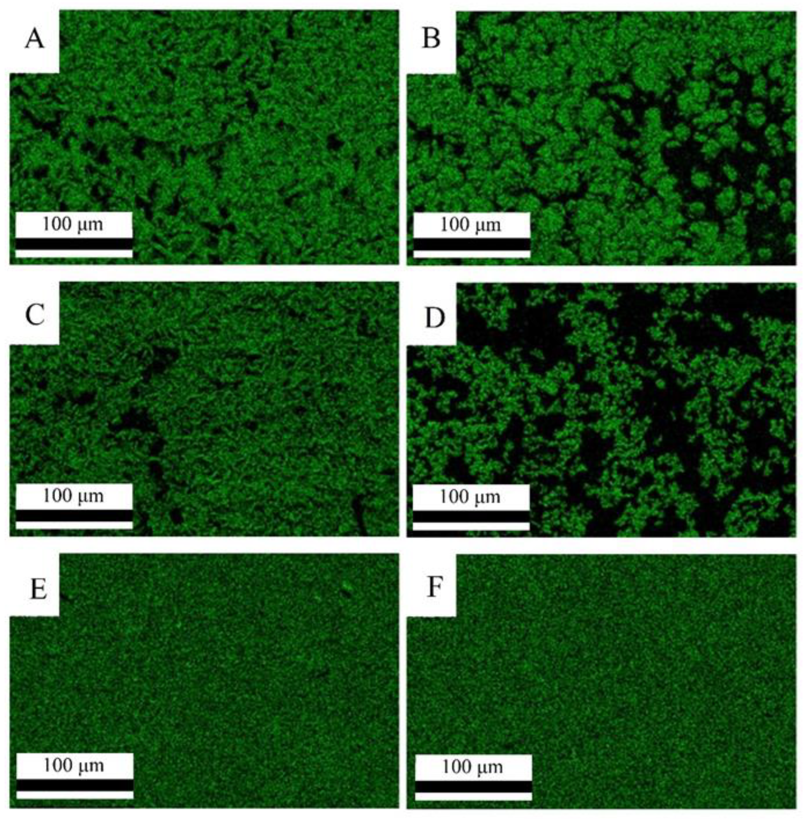
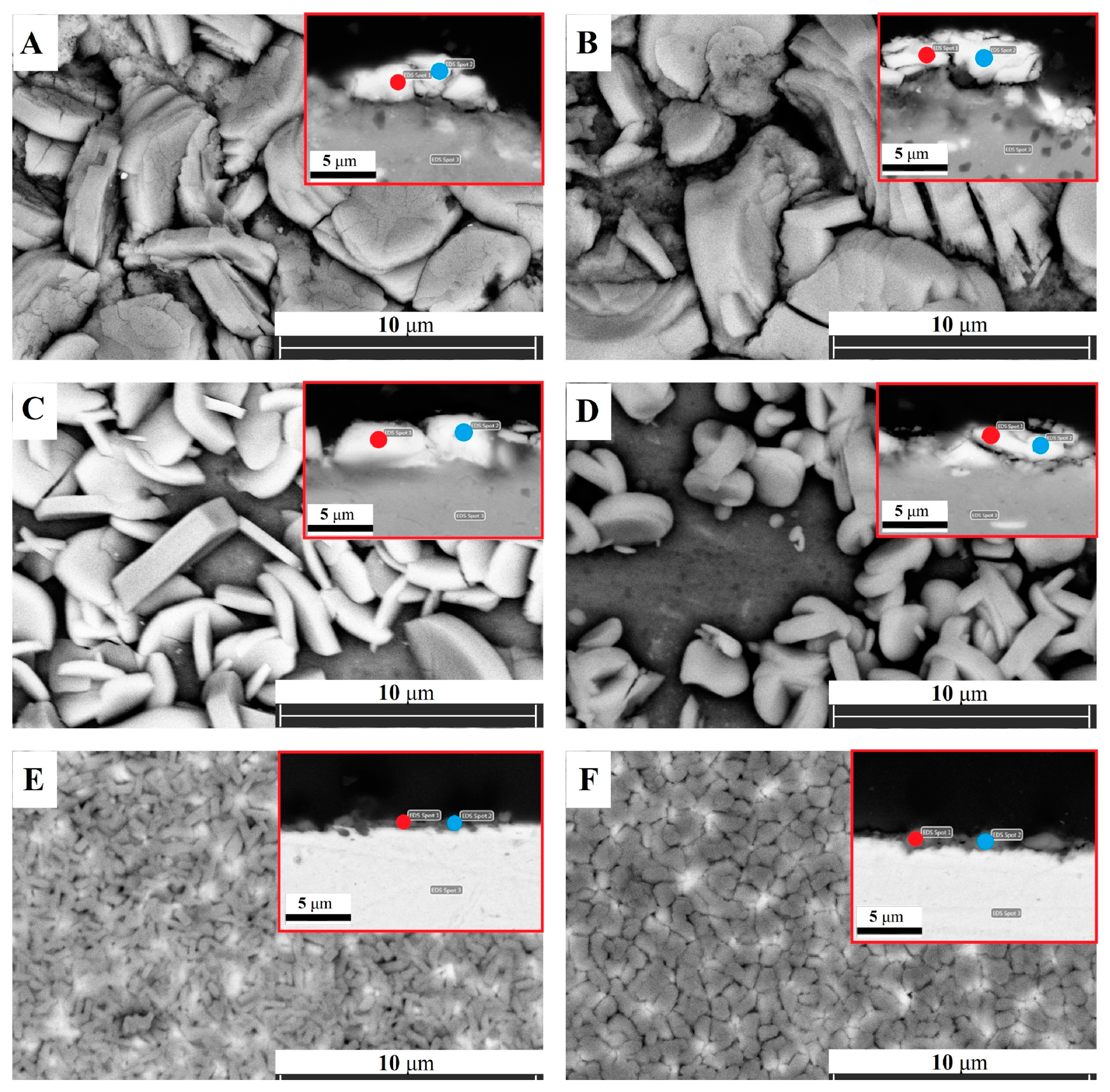
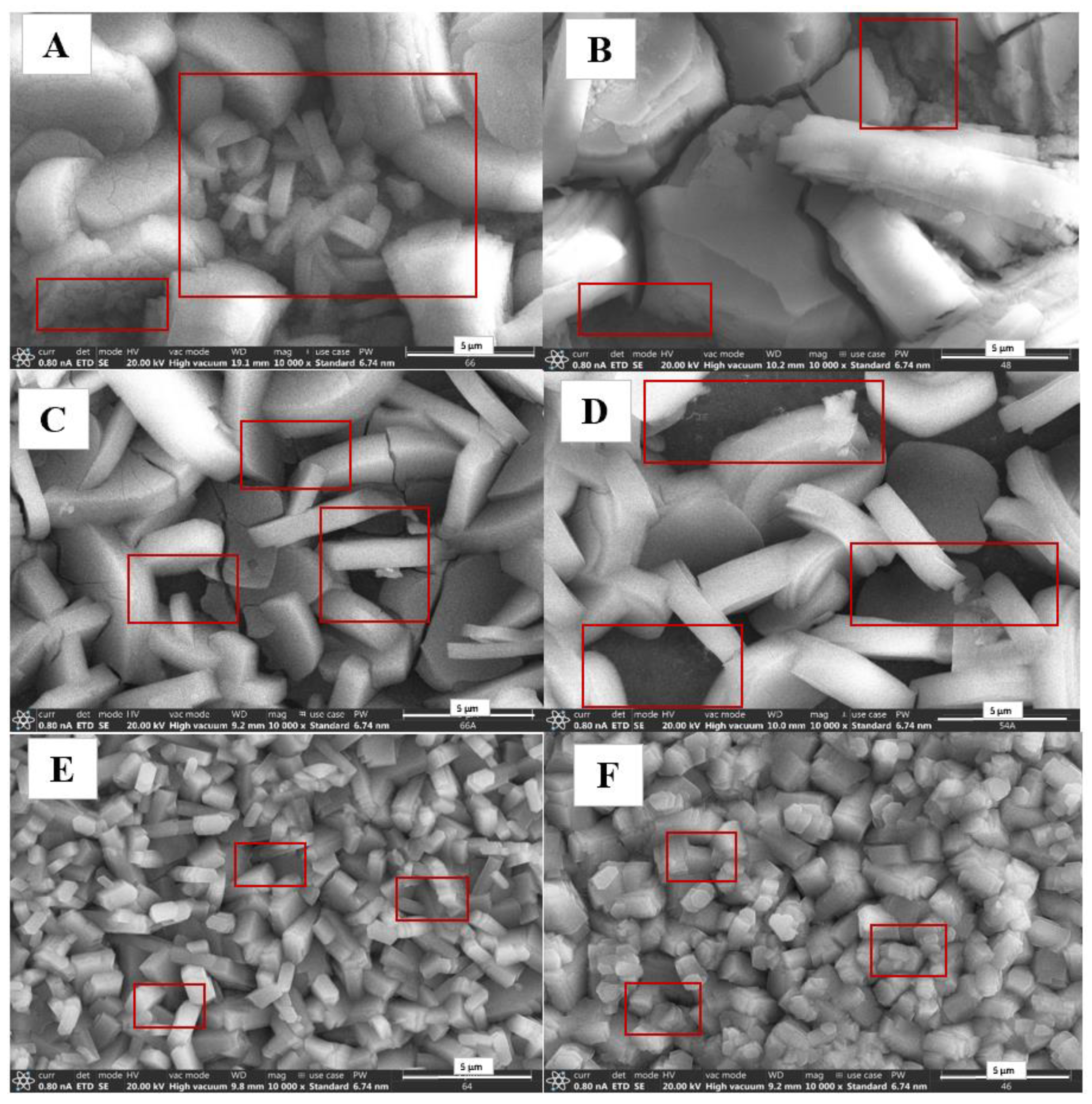
Morphology, crystal shape, and size were tested by FEI/Thermo Fisher Apreo S scanning electron microscope (SEM). Observation by SEM was carried out in low vacuum mode with an accelerating voltage of 20.0 kV. To acquire the best resolution for back-scattered electron imaging of the phosphate-based layers, the samples were washed in ultrasonic bath using ethanol. The samples were embedded in epoxy resin (NXMET XF40), cross sectioned, and finally polished with a 1 µm diamond suspension. The elemental compositions of the samples were determined by an EDAX AMETEK Octane Elect Plus Energy Dispersive X-ray Analyzer. The accelerating voltage was 20 kV and the data collection time was 180 s.
An image analyzer software (Image Color Summarizer 0.76) was used to calculate the surface coverage of the phosphate coating. Color analysis was based on elemental maps obtained by SEM. The pixels of the images were classified into two different clusters, where green pixels represent the phosphor-containing coating and black pixels refer to the aluminum- or iron-based substrate.
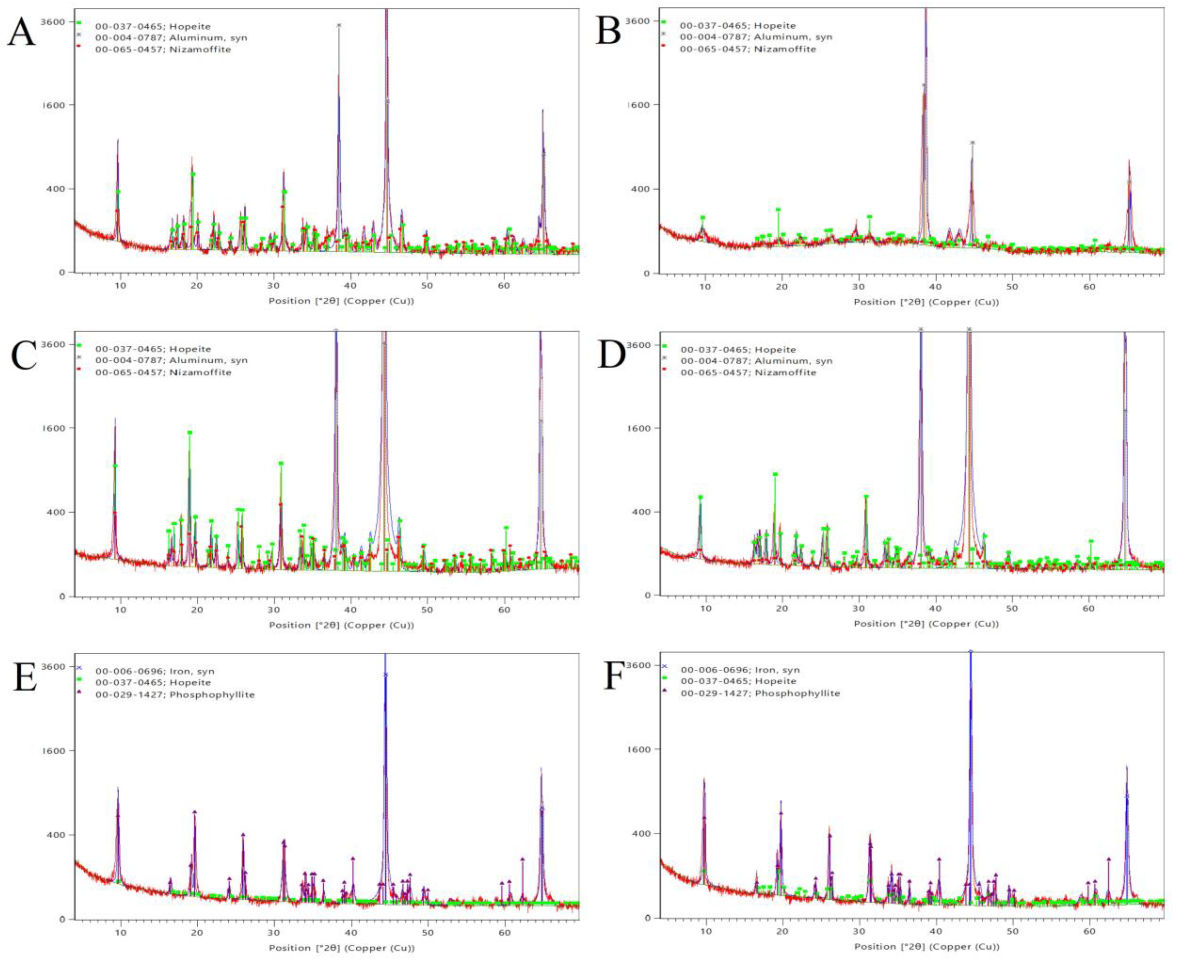
The X-ray diffraction (XRD) analyses of the samples were performed using a Philips PW 3710 diffractometer. The measurement parameters were as follows: CuKα radiation (50 kV, 40 mA), 0.02 °2θ/s speed, the range of 10 to 70°2θ, and a curved graphite monochromator. The X’Pert Data Collector software was used to collect data of XRD pattern data. The HighScore Plus 5.0 software was applied to identify phases and to perform quantitative phase analysis using the Rietveld method. The crystalline phases were identified by comparing the XRD patterns with the 2021 Powder Diffraction Files (PDF-2 2021) of the International Centre of Diffraction Data (ICDD).
A modified scratch-test was used to investigate the adhesion of the coatings. During the examination, an Anton Paar TRB3 type tribometer was used with a total stroke length of 10 mm and a normal force of 1 N throughout the entire measurement. The normal force was kept constant during the tests and the diamond indentation marks on the surface were evaluated using a scanning electron microscope.

2.2. Materials

A wheel hub was chosen as one of the aluminum alloy samples (AL1) as wheel hubs are most often made of aluminum alloy. The sample was sliced without using a cooling medium prior the phosphating process. 
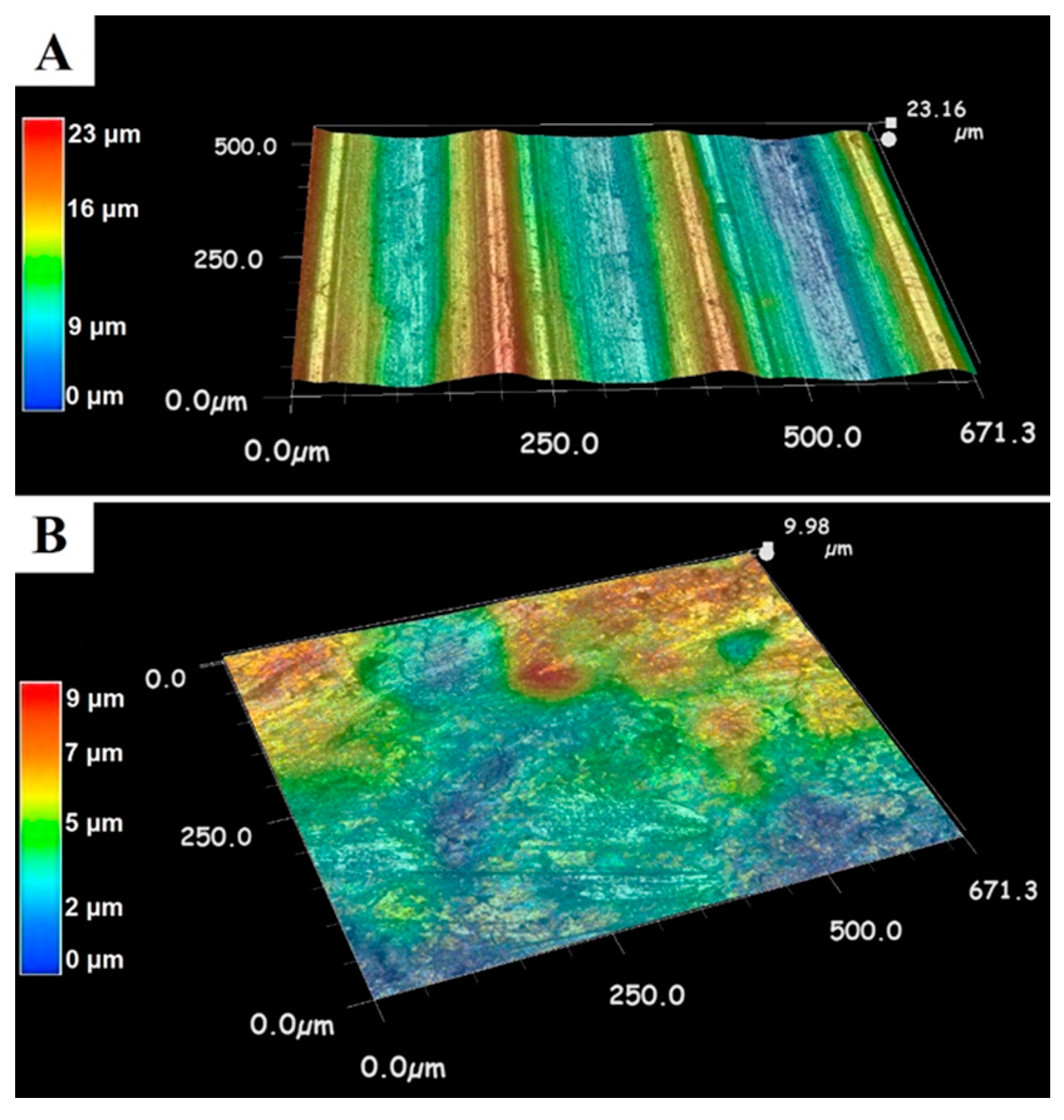
Figure 1 shows the surfaces of the AL1 base alloy, which is a high-strength AlSi1MgMn alloy (EN-AW-6082, Forging Products Trading Spain/CAMARA) designed for high-load structural applications. Thanks to its fine-grained structure, this alloy exhibits good resistance to dynamic loading conditions. This #6000 series aluminum alloy (Si 1~2%; Mg~%) is also suitable for the manufacture of vehicle bodies and for casting [18,25]; it is easy to work and has good corrosion resistance but is difficult to phosphatize [1]. The machined rough surface of the sample (Figure 1A) becomes smoother by forging (Figure 1B). The 3-dimensional LM images (Figure 1) show that the highest roughness value of the raw material is 23 μm, decreasing to 9 μm after forging. During forging, the surface roughness can be significantly reduced. This can help to produce a more uniform zinc phosphate coating. By selecting the appropriate technology, the grain arrangement can be adjusted to the subsequent use to improve the mechanical properties of the piece. This aluminum alloy is also suitable for the manufacture of vehicle bodies; it is easy to machine and it has good corrosion resistance [18] but it is difficult to phosphatize [1]. The elemental composition of AL1 sample measured by OES is given in Table 1, in weight percent (wt.%).
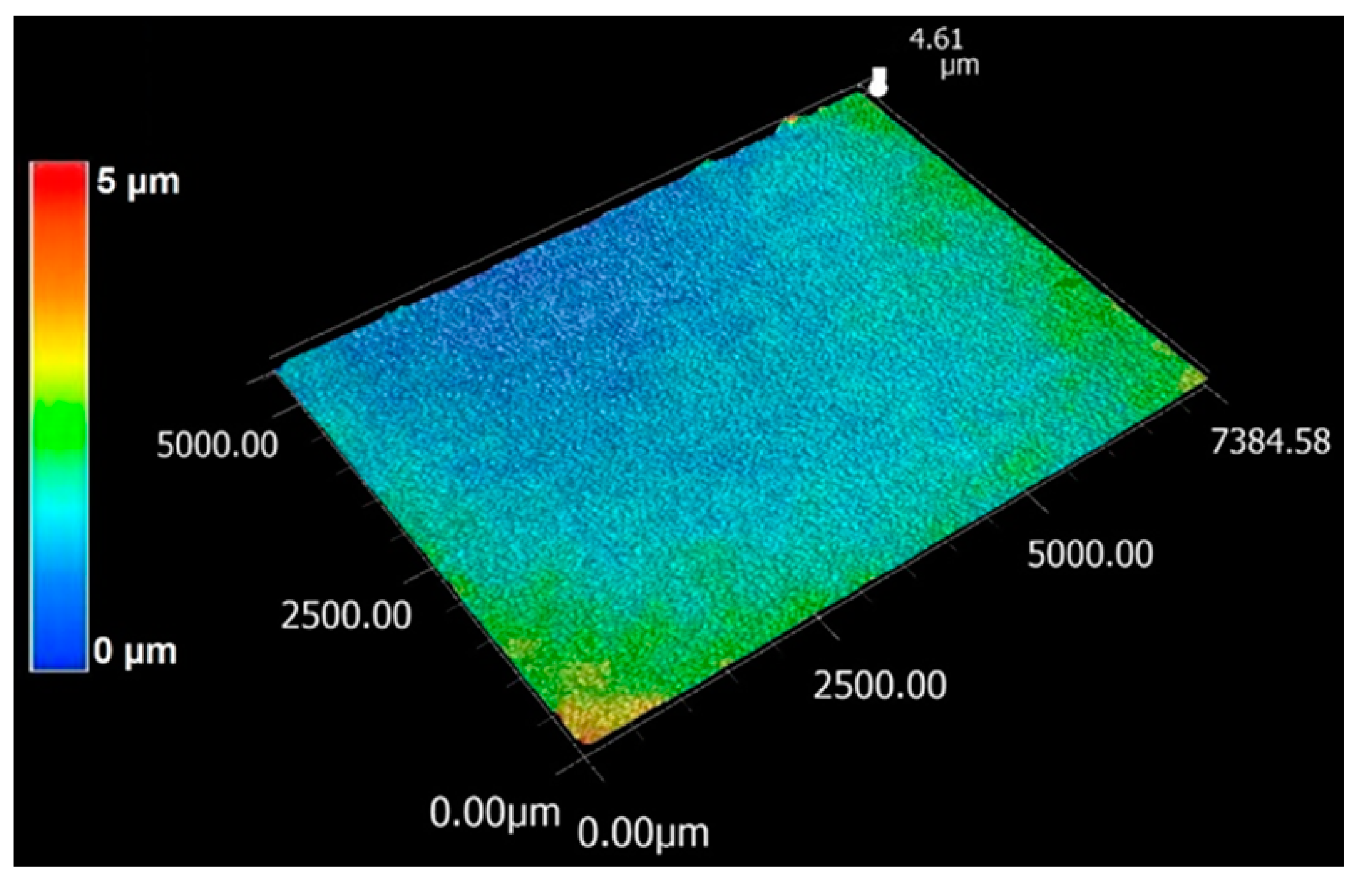
The other raw alloy (AL2) chosen was an AA6014 (AlMg0.6Si0.6V) aluminum alloy panel (Gardobond, Chemetall, Frankfurt am Main, Germany) formed in the T4 temper. The thickness of the rolled aluminum alloy panels was 1.0 mm. The LM image (Figure 2) shows that the highest roughness value for the raw AL2 sample is 5 μm. The #6000 series (Al-Mg-Si) alloys are the most used aluminum alloy plates in automotive bodywork as they possess excellent mechanical properties, are easy to machine and weld, and have good corrosion resistance. They respond well to the high-temperature heating treatment with the burning of electrophoretic paints [25,26] but are difficult to phosphatize [1]. The elemental composition of the AL2 alloy measured by OES is shown in Table 1.
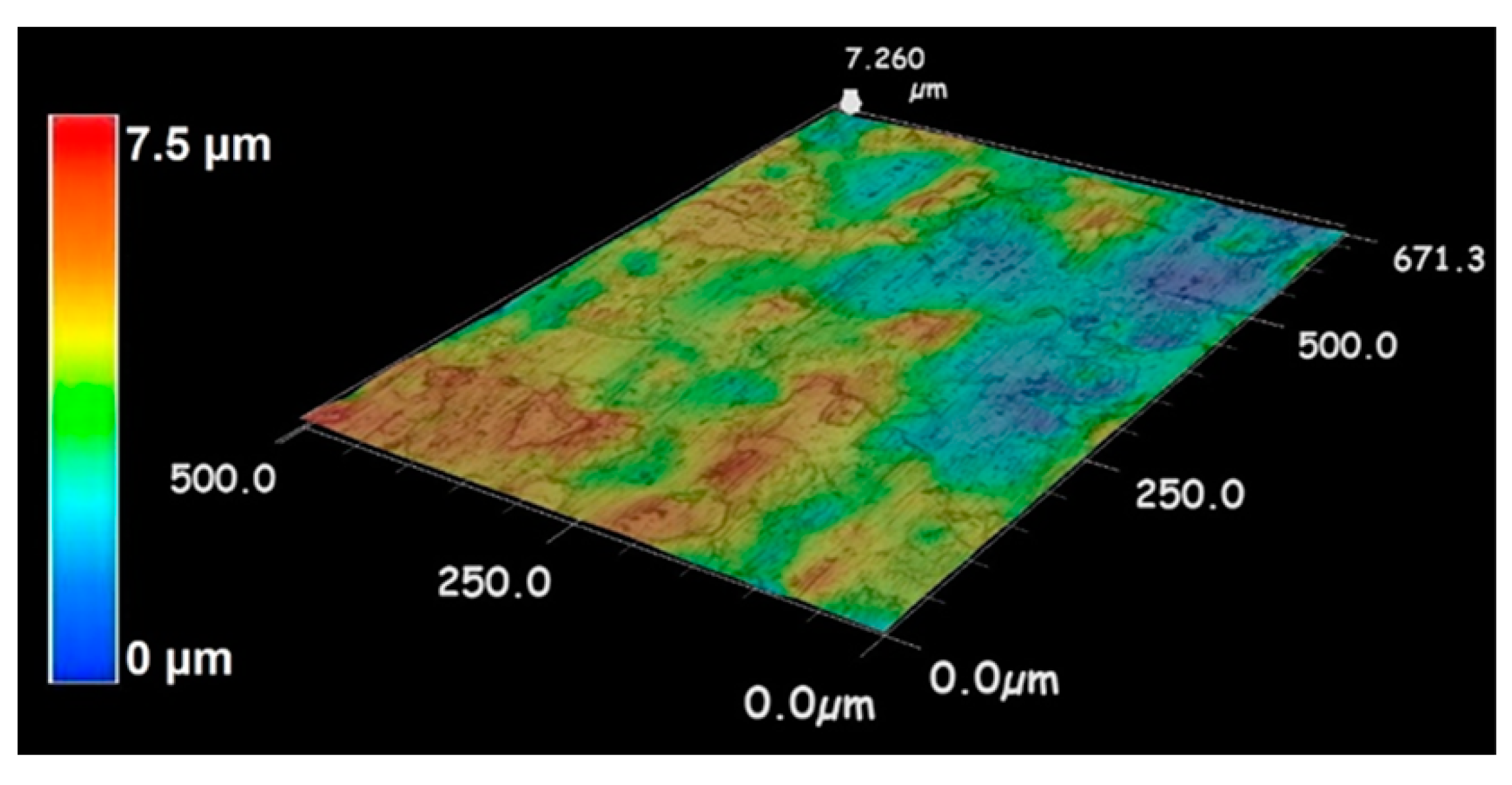
The third studied raw alloy (ST) was a standard low-carbon, cold-rolled, CRS SAE 1008/1010 Type R46 steel panel (Q-Panel) with a thickness of 0.81 mm, temper 1/4 hard. In the case of this rolled steel plate (ST), the highest roughness value is 7.6 μm (Figure 3), which is similar to the AL2 sample. Steel test panels have been recognized as the world standard for a uniform and consistent test surface for paints, adhesives, sealants, and other coatings. These panels are made from standard low-carbon, cold-rolled steel and they have a clean, consistent, and matte surface produced by roughened rolls. The chemical composition of the raw ST sample used in the tests is given in Table 1.

2.3. Preparation of Zinc Phosphate Coating

Phosphating of the alloys was carried out on an industrial production line, thus allowing for the simulation of most of the interfering factors occurring under industrial conditions. The test plates and the test pieces were zinc phosphated without any mechanical surface treatment (polishing, sandblasting, grit blasting, grinding).
The samples were subjected to surface pretreatment and phosphating in the same technological step, using dipping process according to Table A1 for nitroguanidine and Table A2 for nitrite accelerator. After pretreatment, the samples were dried in a laboratory oven.
Important parameters of the phosphate baths are the free acid value (FA), that refers to the free H+ ions present, and the total acid value (TA), that represents the total phosphate content of the phosphating bath [17].
The samples were degreased, rinsed, activated, phosphated and rinsed again in successive steps through different baths. In the degreasing bath(s), oils and greases were removed from the metal surface. In the rinsing bath(s), the degreasing chemicals were removed with water and in the subsequent bath the metal surface was activated. In the phosphating bath, the formation of insoluble heavy metal tertiary phosphates on the surface was carried out, and in the rinsing bath, the removal of acid residues, soluble salts, and non-adhesive particles on the metal was carried out.
Gardobond 2600 zinc phosphate mixture (BASF, Chemetall, Ltd., Frankfurt am Main, Germany) was used for the experiments. This mixture contains zinc, manganese, and nickel (tri-cation bath). This chemical can be used for phosphating steel, galvanized steel, and aluminum alloy surfaces using the dipping and spraying process (“multimetal” process). This is a nitrite (N)-accelerated system but, according to the manufacturer’s technical data sheet (TDS), it can also work with nitroguanidine (NG) accelerator. For both series of experiments with the accelerators, we used a zinc-phosphating solution with identical settings and the accelerators were dosed at the average value according to the technical data sheet. The free fluoride ion content of the phosphating bath used for treating the sample plates was between 140 and 150 ppm, and the total fluoride (SiF62−) was 1.2 to 1.4 g/L during the process, determined by a pH-mV measuring device with fluoride selective electrode (HACH ISEF121; WTW ISE F 500 DIN).
Before the N-accelerated dipping phosphatization process, the samples were degreased with Gardoclean S 5197 (alkaline cleaner for spray and immersion applications; BASF, Chemetall Ltd.), a moderately alkaline, liquid degreasing solution with silicate and borate. It is primarily used for cleaning aluminum alloy, but it is also suitable for cleaning steel and galvanized steel. It can be applied by dipping or spraying. During our tests, it was applied using the dipping method with Gardobond Additive H7400 (BASF, Chemetall, Ltd.) as surfactant, at 60 °C for 600 s, with intensive mixing of the bath. After a water rinse, the surface was activated in the activation bath with Gardolene V6513 solution (BASF, Chemetall Ltd.) at a pH value of 8.9. The zinc phosphating step was carried out using Gardobond 2600 solution (BASF, Chemetall, Ltd.), at a temperature of 53 °C, with 180 s of exposure time. The bath contained 1.3 g/L zinc and 2.4 gas points N accelerator. After the phosphatizing process, a two-step water rinse was completed. To remove residual salt content from the surface, a cascade system of deionized water rinse was used. Finally, the pre-treated pieces were air-dried (Table A2).
Before the NG-accelerated dipping phosphatization process, the samples were degreased with Gardoclean S 5197. It can be applied by dipping or spraying. During our tests, it was applied using the dipping method with Gardobond Additive H7400 (BASF, Chemetall, Ltd.) as surfactant, at 55 °C for 600 s, with intensive mixing of the bath. After a water rinse, the surface was activated in the activation bath with Gardolene V6513 solution (BASF, Chemetall, Ltd.) at a pH value of 8.9. The zinc phosphating step was carried out using Gardobond 2600 solution (BASF, Chemetall, Ltd.) at a temperature of 53 °C, with 180 s of exposure time. The bath contained 500 mg/L NG of accelerator measured by photometry. After the phosphatizing process, a two-step water rinse was completed. To remove residual salt content from the surface, a cascade system of deionized water rinse was used. Finally, the pretreated pieces were air-dried (Table A2).
The compositions of the phosphating baths with different accelerators, as measured by ICP, are summarized in Table 2. In Table 3, the symbols of the phosphate samples are given.

3. Results and Discussion

3.1. SEM Analysis

The low-magnification SEM images of phosphate coatings are shown in Figure 4. On the aluminum alloy samples (AL1-N, AL1-NG, AL2-N, AL2-NG), larger, irregularly arranged crystals of zinc phosphate coating can be observed (Figure 4A–D).
When using N accelerators, the crystal structure is more regular. However, it does not cover the base metal evenly, resulting in visible gaps on the aluminum alloy surfaces (Figure 4A,C). In contrast, the crystals on the steel sheet are smaller and more uniform in size compared to the aluminum alloy surfaces, where large, irregularly arranged crystals are formed (Figure 4E). It is important to note that the corrosion resistance of the phosphate coating is enhanced when the particle size is smaller and more uniform. Additionally, when the surface is covered with irregular overgrowths, the corrosion resistance of the coating is also improved.
The images of Figure 4 demonstrate the surfaces when NG were used as an accelerator. The coating surface is less continuous and the base metal is visible in several places (as shown in Figure 4B,D). In contrast, the shape of the zinc phosphate crystals formed on the surface of the steel samples (Figure 4F) is uniform and covers the base metal effectively with both accelerators. The size of the crystals in these steel samples is smaller than in the aluminum alloy samples, which may result in improved corrosion resistance of the phosphate coating.
To evaluate the homogeneity and continuity of the zinc phosphate coatings, the coverage of the coated surfaces was examined. For this analysis, we used element maps created with TEAM Enhanced V4.5 software, where phosphorus is represented in green and the black color refer to the substrate. The results of the analysis of the images indicate that, in the case of forged aluminum alloy, the coverage can be over 60% (67.23% for AL1-N and 64.67% for AL1-NG) when using either N (Figure 5A) or NG (Figure 5B). However, when coating aluminum alloy with NG (Figure 5D), only 39.71% of the surface was covered. With N application (as shown in Figure 5C), 61.03% of the surface was coated. Thus, in both cases, the coverage is lower than on the forged aluminum alloy surface. The coverage of the steel surface is 100% in each case, as demonstrated by the back-scattered SEM images (Figure 5E,F).
Compared with the SEM images in the studies of Baloyi et al. [27] and Jiang et al. [28], it can be concluded that the Zn2+ concentration (1.3 g/L), bath temperature (53 °C), treatment time (180 s), and accelerator concentration (1.5 points) (see Table A1 and Table A2) used in this study are applicable adjustment parameters, as they promoted the formation of suitable zinc phosphate crystals on the aluminum alloys.
Figure 6A,B illustrate that although there are large and randomly arranged crystals on the surface of the AL1-N and AL1-NG samples, respectively, the spaces between them are filled with smaller crystals (Figure 7A,B) with a size of 1.5 to 3 μm, while the larger crystals have a diameter of 8 to 11 μm. When using NG as an accelerator, better formed, cracked crystals with thicknesses of 1.5 to 4 μm and diameters of 10 to 28 μm were observed. When using N accelerator, regular ring-shaped crystals with thicknesses of 1.1 to 2.7 μm and diameters of 5 to 11 μm can be seen, while with NG, smaller crystals with diameters of 2 to 7 μm and thicknesses of 0.7 to 1.5 μm can be observed.
On the surface of the ST sample (Figure 6E,F), nearly no uncovered surface can be observed (Figure 7E,F). The regularly-grown columnar crystals cover the base metal surface effectively. When using the N accelerator, the formed crystals are 600 to 800 nm thick and 1.1 to 1.8 μm long. In contrast, when using the NG accelerator, 1 to 3 μm tightly fitting crystals cover the surface.
Comparing the crystal structures to SEM images published by Fetis [1] and Baloyi et al. [28], it is necessary to increase the fluoride content used in this study to obtain a coating with finer crystal structure on aluminum alloy surfaces, depending on how the ratio of aluminum content to other metals changes during the pickling process. Kok et al. [25] propose an optimal range of F- content between 200 and 400 ppm for normal zinc content bath and 600 and 1000 ppm for low-zinc content pickling processes. However, based on this study, it is not necessary to dose at such a high rate.
On the cross-sectional images (Figure 6) marked with a red frame, it is clearly visible that the surface irregularities of the forged aluminum alloy sample are not covered with crystals (Figure 6A,B). The coating in this case is single layered, with a thickness of 2 to 4 μm, regardless of the type of accelerator. The surface of the rolled aluminum alloy (Figure 6C,D) is well covered due to the very low roughness of the metal base, and the irregular but smaller-sized phosphate particles can be seen in the gaps between the large crystals (Figure 7C,D). In terms of the thickness of the coating, there is no difference in this case either (typically 1.5 to 3.5 μm for both types of accelerators). For rolled steel sheets (Figure 6E,F), the coating is much thinner than for aluminum alloy, typically less than 1 μm, but it is clearly visible that the coating completely covers the surface (Figure 7E,F). This is also confirmed by the calculation of the surface coverage.
Large and randomly arranged crystals were observed on the surface of AL1-N and AL1-NG samples (Figure 7A,B), where the spaces between them are filled with smaller crystals. On the surface of the AL2-N and AL2-NG plates, a thin layer of coating can be seen on the uncovered regions (Figure 7C,D). For ST-N and ST-NG samples, there is almost no uncovered surface; the regularly grown columnar crystals cover the steel surface (Figure 7E,F). By comparing the high-resolution SEM images (Figure 7) with similar micrographs published by Cheng et al. [19], Narayan [2] and Tegehall et al. [23], it can be concluded that the phosphating bath composition and treatment time resulted a properly structured zinc phosphate layer for the subsequent paint layer on all three base metals.
The composition of the phosphate crystals was measured using EDX analysis. Spot analysis was applied on cross-sectional polished samples and the results are summarized in Table 4. The presence of manganese and nickel on the coated surfaces of various metals is clear. The manganese content of the coatings of forged aluminum alloy (AL1) and steel samples (ST) increased more than tenfold when compared to the base metal composition given in Table 1 (From 0.58 wt.% to 9.50 wt.% and from 0.36 wt.% to 9.87 wt.%, respectively). Meanwhile, for the rolled aluminum alloy plate, manganese content increased more than thirtyfold (from 0.11 wt.% to 36.3 wt.%). The results were similar regardless of the applied accelerator. The nickel content of the AL1 sample (original nickel content of 0.006 wt.%) was, on average, 1.1 wt.% with both accelerators, while for the AL2 sample (nickel content in the substrate of 0.006 wt.%), it was 0.73 wt.% with nitrite and 0.99 wt.% with nitroguanidine. Using nitrite accelerators, the nickel content of the rolled steel samples increased about 50 times (from 0.024 wt.% to 0.22 wt.%) and with nitroguanidine, it increased 30 times, from 0.024 wt.% to 0.7 wt.%. Based on these results, it is assumed that manganese and nickel can incorporate into the hopeite formed on the aluminum alloy surface and into the phosphophyllite crystal phases on the rolled steel surface [3,16].

3.2. XRD Analysis

In the XRD patterns of the aluminum alloy samples (Figure 8A–D), besides the strong reflections of the substrate aluminum, reflections of the hopeite-type phase are clearly identified for both accelerators. Comparing XRD patterns of surfaces prepared with N and NG accelerators, the use of N leads to stronger (higher intensity) reflections of the hopeite-type phase. Using the PDF00-065-0457 and the PDF00-036-0266 (not presented) reference files, it can be established that the nizamoffite (MnZn2 (PO4)2·4H2O) (red) and the Mn2Zn(PO4)2·4H2O phases have all their reflections strongly overlapping with the hopeite and no separate reflections, therefore a crystalline phase closer to the hopeite is more likely in the coating. Doerre et al. [3] demonstrated that the general formula of phosphate coating formed in tri-cationic bathes with low Zn concentration can be given as Zn3-x-z(NixMn2)(PO4)2 · 4H2O. This description is consistent with the present XRD results, where we could detect the formation of a single phosphate phase. Using the EDX results of Zn, Mn, and Ni (Table 4), the formula of hopeite-type phase formed on AL1-N, AL1-NG, AL2-N, and AL2-NG was calculated. All formulas can be given as Zn2.3(Ni0.1Mn0.6)(PO4)2·4H2O.
In the reviews of the phosphating process [3,4], the formation of Mn2Zn(PO4)2·4H2O is highlighted in addition to hopeite when Mn-containing baths are used on aluminum alloys. Our investigations showed that only one type of crystalline phase (Zn2.3(Ni0.1Mn0.6)(PO4)2·4H2O) closer to hopeite phase was formed in the coating of both aluminum alloy samples with both accelerators. This means that the composition of the tricationic bath determines the composition of the resulting coating. This finding is consistent with the literature [3,16], which note that the presence of Ni and Mn ions can cause the modification of hopeite phase.
In the XRD patterns of the ST steel surface (Figure 8E,F), besides the strong reflections of the substrate iron, phosphophyllite is clearly the main phase constituent for both accelerators, while hopeite is only a minor constituent. When comparing the XRD patterns of the surfaces prepared with N and NG accelerators, it can be stated that there is no significant difference in the intensity of the reflection of the phosphophyllite and hopeite phases. For an accurate characterization of the phase composition, the amount of phophophyllite and hopeite was determined using the Rietveld method. The amount of phosphophyllite was 94% and 95% in the coatings prepared with N and NG accelerators, respectively. According to the literature [2,6,8], phosphate layers with a higher phosphophyllite content can serve as effective conversion coatings during cathodic electrophoretic painting, paint curing, and under service conditions.

3.3. Scratch Test

The pressure channel areas are summarized in Figure 9. For the examination, rolled aluminum alloy and steel plates were chosen, as the curved surface of the forged aluminum alloy does not allow for precise measurement.
The structure of the nitrite-accelerated coating on the aluminum alloy surface (AL2-N) is illustrated in Figure 9A after the scratch test. It is observed that the zinc phosphate layer has not detached from the surface and no micro-cracks have formed in the vicinity of the scratch. The zinc phosphate crystals became dull on the surface due to the diamond indenter, indicating that the coating is not rigid and has favorable elastoplastic properties and good adhesion.
On the AL2-NG sample (Figure 9B), most of the crystals detached from the surface and a small portion of them were embedded into the aluminum alloy substrate. This phenomenon suggests that if a small number of tiny crystals form on the surface, they are less likely to adhere well to the surface.
The zinc phosphate coating formed on the rolled steel surface (ST-N and ST-NG) behaved similarly during the scratch-test for nitrite (Figure 9C) and nitroguanidine (Figure 9D) accelerators. The back-scattered electron images show that the coating around the pressure channel did not crack and did not come apart from the substrate. Under the diamond indenter, the steel partially adhered to the surface of the coating, indicating that even though the zinc phosphate is thin, its adhesion is excellent.

4. Conclusions

During the simultaneous zinc phosphatization of steel and aluminum alloy, special attention must be paid to the fluoride dosage in order to from a properly structured phosphate layer on the surfaces. It has been demonstrated that zinc phosphate layer can be formed on the surface using nitrite and nitroguanidine accelerators if fluoride is added during the pickling reaction. It was proven that greater surface coverage can be achieved on the aluminum alloy samples using nitrite accelerator, but there is no significant difference in zinc phosphate coverage on the steel samples with different accelerators. SEM examinations confirmed that various crystal structures with different thicknesses were formed depending on the quality of the substrate. The scratch-tests also confirmed that, even if the coating is thin, its adhesion is excellent, and it does not come off the surface. The composition of the crystalline phase (Zn2.3(Ni0.1Mn0.6)(PO4)2·4H2O) formed on the surface of forged and/or rolled aluminum alloy samples is similar to that of the hopeite, while it was primarily phosphophyllite (~95%) that was formed on the steel samples during the same treatment. The nitroguanidine accelerator, that was used for environmental protection reasons, yields satisfactory results when used for the pretreatment of steel and aluminum alloys with the same technological parameters and bath composition, as when nitrite was used as an accelerator.

Author Contributions

Conceptualization, B.H., K.K., M.J. and É.M.; methodology, B.H., K.K., M.J. and É.M.; software, B.H., M.J. and É.M.; validation, B.H., K.K., M.J. and É.M.; formal analysis, B.H. and M.J.; investigation, B.H., K.K., M.J. and É.M.; resources, B.H. and K.K.; data curation, B.H., M.J. and É.M.; writing—original draft preparation, B.H. and M.J.; writing—review and editing, B.H., K.K., M.J. and É.M.; visualization, B.H. and M.J.; supervision, K.K.; project administration, B.H. and M.J. All authors have read and agreed to the published version of the manuscript.

Funding

This research received no external funding.

Institutional Review Board Statement

Not applicable.

Informed Consent Statement

Not applicable.

Data Availability Statement

Not applicable.

Conflicts of Interest

The authors declare no conflict of interest.

Appendix A

Table A1. Process parameters of zinc phosphating with nitroguanidine accelerator.
Process StepProcess TypeName of SolutionConcentrationTemperatureTime of ProcessingMode of OperationChemical Bath Parameters
[g/L][°C][s]
1.DegreasingGardoclean S 51973060600Dip
GBA H 74003
2.Rinsescity water Room Temp.60Dip
3.Surface ActivationGardolene V 65131Room Temp.60DippH: 8.9
4.PhosphatingGardobond 2600 53180DipFA(KCl): 1.5 points; TA: 22 points
Zn: 1.3 g/L; Acc.: 0.0.5 g/L
5.Rinsescity water Room Temp.30Dip
6.Final Rinsedeionized water Room Temp. Dipconductivity: <20 µS/cm
7.Drying 120600Oven
Table A2. Process parameters of zinc phosphating with nitrite accelerator.
Process StepProcess TypeName of SolutionConcentrationTemperatureTime of ProcessingMode of OperationChemical Bath Parameters
[g/L][°C][s]
1.DegreasingGardoclean S 51973060600Dip
GBA H 74003
2.Rinsescity water Room Temp.60Dip
3.Surface ActivationGardolene V 65131Room Temp.60DippH: 8.9
4.PhosphatingGardobond 2600 53180DipFA(KCl): 1.4 points; TA: 22 points
Zn: 1.3 g/L; Acc.: 2.4 gas point
5.Rinsescity water Room Temp.30Dip
6.Final Rinsedeionized water Room Temp. Dipconductivity: <20 µS/cm
7.Drying 120600Oven

References

  1. Fettis, G. Automotive Paints and Coatings; VCH Verlagsgesellschaft mbH: Weinheim, Germany, 1995. [Google Scholar]
  2. Narayan, C.D. Importance of Surface Preparation for Corrosion Protection of Automobiles. J. Surf. Eng. Mater. Adv. Technol. 2013, 3, 94–105. [Google Scholar]
  3. Doerre, M.; Hibbitts, L.; Patrick, G.; Akafuah, N.K. Advances in Automotive Conversion Coatings during Pretreatment of the Body Structure: A Review. Coatings 2018, 8, 405–421. [Google Scholar] [CrossRef] [Green Version]
  4. Donofrio, J. Zinc Phosphating. Met. Finish. 2000, 98, 57–73. [Google Scholar] [CrossRef]
  5. Akafuah, N.K.; Poozesh, S.; Salaimeh, A.; Patrick, G.; Lawler, K.; Saito, K. Evolution of the automotive body coating process—A review. Coatings 2016, 6, 24. [Google Scholar] [CrossRef] [Green Version]
  6. Rausch, W. Die Phosphatierung von Metallen; 3. Auflage; Eugen G. Leuze Verlag: Bad Saulgau, Germany, 2005. [Google Scholar]
  7. Su, H.Y.; Lin, C.S. Effect of additives on properties of phosphate conversion coating on electrogalvanized steel sheet. Corros. Sci. 2014, 83, 137–146. [Google Scholar] [CrossRef]
  8. Zhu, L.Z.; Hang, J.H.; Chen, X. Investigation on the adhesion improvement of organic coatings on the surface of hot-dip galvanized steel. IOP J. Phys. Conf. Ser. 2020, 1605, 012128. [Google Scholar] [CrossRef]
  9. Shibli, S.M.A.; Chacko, F. Development of nano TiO2-incorporated phosphate coatings on hot dip zinc surface for good paintability and corrosion resistance. Appl. Surf. Sci. 2011, 257, 3111–3117. [Google Scholar] [CrossRef]
  10. Maeda, S. Surface chemistry of galvanized steel sheets relevant to adhesion performance. Prog. Org. Coat. 1996, 28, 227–238. [Google Scholar] [CrossRef]
  11. Abdalla, K.; Rahmat, A.; Azizan, A. Effect of copper (II) acetate pretreatment on zinc phosphate coating morphology and corrosion resistance. J. Coat. Technol. Res. 2013, 10, 133–139. [Google Scholar] [CrossRef]
  12. Abdalla, K.; Rahmat, A.; Azizan, A. The effect of pH on zinc phosphate coating morphology and its corrosion resistance on mild steel. Adv. Mat. Res. 2013, 626, 569–574. [Google Scholar] [CrossRef]
  13. Tamilselvi, M.; Kamaraj, P.; Arthanareeswari, M.; Devikala, S. Nano zinc phosphate coatings for enhanced corrosion resistance of mild steel. Appl. Surf. Sci. 2015, 327, 218–225. [Google Scholar] [CrossRef]
  14. Duszczyk, J.; Siuzdak, K.; Klimczuk, T.; Strychalska-Nowak, J.; Zaleska-Medynska, A. Modified manganese phosphate conversion coating on low-carbon steel. Materials 2020, 13, 1416. [Google Scholar] [CrossRef] [Green Version]
  15. Joshihara, T.; Okita, H. Phosphate Coating Techniques for Car Bodies. Trans. Iron Steel Inst. Jpn. 1983, 23, 984–993. [Google Scholar] [CrossRef]
  16. Narayanan, T.S.N.S. Surface Pretreatment by Phosphate Conversion Coating—A review. Rev. Adv. Mater. Sci. 2005, 9, 130–177. [Google Scholar]
  17. Machu, W. Nichtmetallische Anorganische Überzüge; Springer: Vienna, Austria, 1952. [Google Scholar]
  18. Mallick, P.K. Materials, Design and Manufacturing for Lightweight Vehicles; Woodhead Publishing Limited: Cambridge, UK, 2010. [Google Scholar]
  19. Cheng, B.; Ramamurthy, S.; McIntyre, N.S. Characterization of phosphate films on aluminum surfaces. J. Materi. Eng. Perform. 1997, 6, 405–412. [Google Scholar] [CrossRef]
  20. Lohmeyer, S. Phosphatierfehler aus Zink und Alkaliphosphatierungen; Eugen G. Leuze Verlag: Saulgau/Würt, Germany, 1993. [Google Scholar]
  21. Zhang, S.; Chen, H.; Zhang, X.; Zhang, M. The grow of zinc phosphate coating on 6061-Al alloy. Surf. Coating. Technol. 2008, 202, 1674–1680. [Google Scholar] [CrossRef]
  22. Bender, H.S.; Cheever, G.D.; Wojtkowiak, J.J. Zinc Phosphate Treatment of Metals. Prog. Org. Coat. 1980, 8, 241–274. [Google Scholar] [CrossRef]
  23. Tegehall, P.E.; Vannerberg, N.G. Nucleation and Formation of Zinc Phosphate Conversion Coating on Cold-Rolled Steel. Corros. Sci. 1991, 32, 635–652. [Google Scholar] [CrossRef]
  24. Zhang, S.; Zhang, X.; Zhang, M. Zinc phosphating of 6061-A1 alloy using REN as additive. J. Rare Earth. 2008, 26, 110–114. [Google Scholar] [CrossRef]
  25. Ota, Y.; Masuda, T.; Kimura, S. Technical Trends in Aluminum Alloy Sheets for Automotive Body Panels. Kobelco Technol. Rev. 2020, 38, 16–20. [Google Scholar]
  26. Kok, W.H.; Sun, X.; Shi, L.; Wong, K.C.; Mitchell, K.A.R.; Foster, T. Formation of zinc phosphate coatings on AA6061aluminum alloy. J. Mater. Sci. 2001, 36, 3941–3946. [Google Scholar] [CrossRef]
  27. Baloyi, T.; Maledi, N.; Andrews, A. Corrosion performance of zinc phosphate coatings deposited on AA-6061- HDG steel. Mater. Chem. Phys. 2022, 126009. [Google Scholar] [CrossRef]
  28. Jiang, C.; Gao, Z.; Pan, H.; Cheng, X. The initiation and formation of a double-layer phosphate conversiom coating on steel. Electr. Chem. Commun. 2020, 114, 1066676. [Google Scholar]
Figure 1. LM images of the piece of the truck wheel hub (AL1), the cast and machined surface (A), the cast and forged surface (B).
Crystals 13 00369 g001
Figure 2. 3-dimensional LM image of the AA6014 aluminum alloy test plate (AL2).
Crystals 13 00369 g002
Figure 3. 3-dimensional LM image of steel alloy test plate (ST).
Crystals 13 00369 g003
Figure 4. The back-scattered SEM images of phosphate coatings: AL1-N (A), AL1-NG (B), AL2-N (C), AL2-NG (D), ST-N (E), ST-NG (F).
Crystals 13 00369 g004
Figure 5. The distribution of phosphor atoms on the surface of the samples: AL1-N (A), AL1-NG (B), AL2-N (C), AL2-NG (D), ST-N (E), ST-NG (F).
Crystals 13 00369 g005
Figure 6. The higher magnification SEM images of the phosphate coatings: AL1-N (A), AL1-NG (B), AL2-N (C), AL2-NG (D), ST-N (E), ST-NG (F). The parts marked with a red square show the images of the cross-sectional grindings.
Crystals 13 00369 g006
Figure 7. SEM images of the phosphate coatings: AL1-N (A), AL1-NG (B), AL2-N (C), AL2-NG (D), ST-N (E), ST-NG (F). The parts marked with a red square show the gaps.
Crystals 13 00369 g007
Figure 8. The XRD patterns of phosphate coatings: AL1-N (A), AL1-NG (B), AL2-N (C), AL2-NG (D), ST-N (E), ST-NG (F).
Crystals 13 00369 g008
Figure 9. Pressure channel formed after scratch test: AL2-N (A), AL2-NG (B), ST-N (C), ST-NG (D).
Crystals 13 00369 g009
Table 1. The chemical composition of raw alloys.
Element [wt.%]AlCFeSiMnMgCuCrTiNiZnPSMo
AL197.3-0.240.950.580.700.0420.130.0190.0060.034---
AL298.4-0.2250.610.110.54<0.0020.130.0190.0060.034---
ST0.0390.07599.20.0130.36--0.084-0.024-0.0060.0100.008
Table 2. The chemical composition of phosphating bath with nitrite (N) and nitroguanidine (NG) accelerator.
Element [mg/L]AlAsBBaCaCdCoCrCuFeKMgMn
NG4<2<1<0.51<0.5<0.5<0.5<0.516<2000<0.5940
N1.5<2<1<0.50.5<0.5<0.5<0.5<0.511<2000<0.5910
Element [mg/L]NaNiPPbSSbSiSnSrTiVZnZr
NG25009405600<219<2200<2<0.5<0.5<0.51330<0.5
N27509205200<218<2185<2<0.5<0.5<0.51280<0.5
Table 3. Symbols of the phosphated samples.
SampleSubstrateAccelerator
AL1-Nforged aluminum castingnitrite
AL1-NGforged aluminum
casting
nitroguanidine
AL2-Nrolled aluminumnitrite
AL2-NGrolled aluminumnitroguanidine
ST-Ncold rolled steel (CRS)nitrite
ST-NGcold rolled steel (CRS)nitroguanidine
Table 4. The relative chemical composition of zinc phosphate crystals determined by the EDX analysis of the cross-section of samples as the average of the red and blue points in Figure 6. (The data are presented without the 38–58% oxygen content due to the uncertainty of its quantification).
Atomic Percent [%]
SampleMgAlSiPMnFeNiZn
AL1-N1.547.80.323.55.2-0.920.7
AL1-NG2.741.20.629.55.7-1.219.3
AL2-N0.444.20.928.65.1-1.019.7
AL2-NG0.748.90.625.64.2-0.819.0
ST-N--0.215.35.056.10.422.9
ST-NG--0.332.63.738.20.824.3
Disclaimer/Publisher’s Note: The statements, opinions and data contained in all publications are solely those of the individual author(s) and contributor(s) and not of MDPI and/or the editor(s). MDPI and/or the editor(s) disclaim responsibility for any injury to people or property resulting from any ideas, methods, instructions or products referred to in the content.

