Review

A Comprehensive Review of Large-Strain-Extrusion Machining Process for Production of Fine-Grained Materials

by
Muralimohan Gurusamy
1 and
Balkrishna C. Rao
2,*
1
School of Mechanical Engineering, Vellore Institute of Technology, Chennai Campus, Chennai 600127, India
2
Sustainable Manufacturing Laboratory, Department of Engineering Design, Indian Institute of Technology Madras, Chennai 600036, India
*
Author to whom correspondence should be addressed.
Crystals 2023, 13(1), 131; https://doi.org/10.3390/cryst13010131
Submission received: 8 December 2022 / Revised: 4 January 2023 / Accepted: 10 January 2023 / Published: 11 January 2023

Abstract

:
Bulk nanostructured metals and alloys are finding increasing structural applications due to their superior mechanical properties. The methods that rely on the severe plastic deformation technique for effecting microstructural refinement through imposing large strains are utilized mostly to produce nanostructured materials. The machining process has been demonstrated as a simple process for severe plastic deformation by imposing large strains through a single pass of the cutting tool where strains in a range of 1–15 can be imposed for a variety of materials by varying the cutting conditions and tool geometry. However, the geometry of the resulting chip subjected to severe plastic deformation during the machining process is not under control and, hence, a variant of the machining process, called the large-strain-extrusion machining process, has been proposed and utilized extensively for producing bulk nanostructured materials. Large-strain-extrusion machining possesses simultaneous control over microstructure refinement, through managing the strain during large-strain machining, and the shape and dimension of the resulting chip by the extrusion process. This study provides a comprehensive review of the large-strain-extrusion machining process by presenting the findings related to the utilization of this process for the production of fine-grained foils for various metals and alloys. Further research efforts related to finite-element modelling of large-strain-extrusion machining and their usefulness in designing the experimental setup and process conditions are also discussed.

1. Introduction

The presence of submicron-size grains in nanostructured materials provides them with some novel attributes compared to the conventional materials [1,2]. The level of microstructure refinement attained by varying the grain size has a greater impact on these novel characteristics of higher hardness, strength, ductility, and difference in electrical and magnetic properties [1,3,4]. Further superplasticity has also been observed in these nanostructured materials at relatively low temperatures [5,6]. Though nanostructured materials possess more benefits compared to conventional materials, they are not widely utilized for many applications due to the cost involved in the production process. Severe plastic deformation (SPD) in large-strain deformation has been increasingly utilized as a method to produce bulk nanostructured materials through microstructure refinement, effected by reductions in the grain size due to the imposition of large strains [7,8,9]. In this regard, the conventional manufacturing processes involving large-scale deformation, such as rolling, drawing, equal channel angular extrusion (ECAE), or high-pressure torsion, has been utilized. However, multiple passes are required in these SPD processes to impose very high strains of more than 4 with each pass effecting a strain of approximately 1 [10]. Further, these SPD processes are not suitable for high-strength metals and alloys in imposing large strains and, mostly, this SPD approach is restricted to produce nanostructured bulk material from low- to medium-strength ductile metal and alloys [8]. Further, these SPD techniques require multiple passes to impose high strain and, hence, the large-scale production of bulk nano-structured materials is cumbersome and expensive. In order to overcome these difficulties machining, was explored as an SPD technique since the chips produced during machining were found to have nano-crystalline structures, as they are subjected to very large shear strains [11].
Machining is a manufacturing process where excess material is removed from the workpiece to produce a finished component, with the desired dimensions and surface finish. It is a three-dimensional process, as shown in Figure 1, where a cutting tool with a sharp cutting edge would move longitudinally at a feed of (f) relative to the revolving workpiece, hence, reducing the diameter of the workpiece by the depth of cut (to) while the workpiece revolves at a certain rotational speed corresponding to a linear cutting velocity of V. It should be noted that the metal cutting process shown in Figure 1 is called turning, which is a classic representation of oblique or three-dimensional processes.
In machining, the work material is subjected to large values of strain in the order of 1 to 10 and strain rates of up to 106/s and temperatures in a range of 0.1 to 0.7 Tm (melting temperature) in a narrow cutting zone called the shear plane [12,13,14], as shown in Figure 2. The machining process is capable of imposing large values of strain and strain rate in a single pass, which is significantly higher than the strain and strain rate values that can be achieved, even through multiple stages of deformation using other SPD processes. Thus, machining has been utilized as an SPD technique to produce fine-grain materials from various metals and alloys [15]. A range of strain and strain rate values can be imposed in the machining process by altering the machining parameters, but since it is an unconstrained deformation process, it does not have control over shape and dimensions of the chip that is being cut from the work material [15]. In this regard, a constrained machining process, called large-strain-extrusion machining (LSEM), has been developed and explored as an SPD technique for producing bulk fine-structured materials with predefined geometry from various metals and alloys [16]. In the succeeding sections, the details of the LSEM process and its capabilities, application of LSEM for production of fine-grain materials from different metals and alloys, numerical modelling of LSEM, and its current status are discussed.

2. Large-Strain-Extrusion Machining

The present section will provide a detailed description of the LSEM process utilized for producing a continuous or small strip of ultrafine-grain UFG foils [17,18,19,20,21]. LSEM is a constrained machining operation for obtaining a chip that has ultrafine-grain microstructure with a controlled shape and size. This process is carried out either through an orthogonal cutting or a conventional turning approach, with certain modifications in the tool and fixtures. Smaller strips are obtained when the orthogonal cutting configuration is implemented, as shown in Figure 3, and continuous chips are possible when the turning approach is utilized.

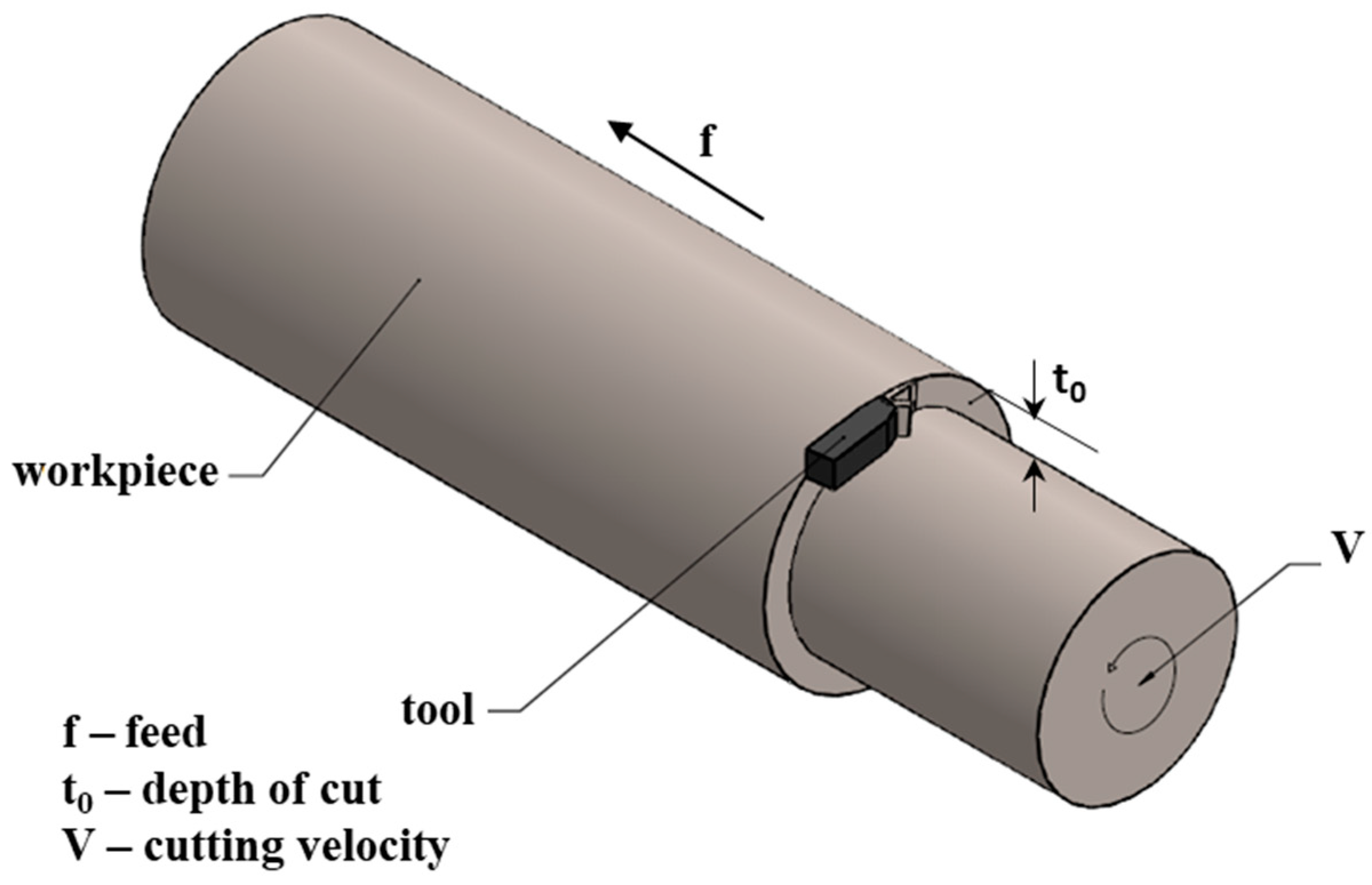
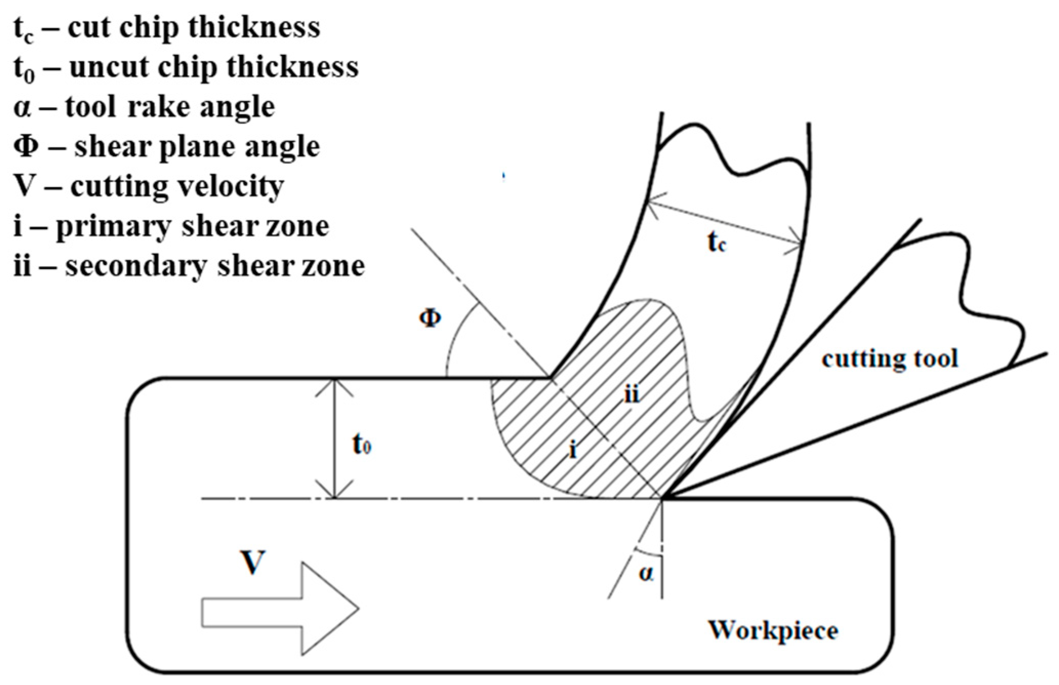
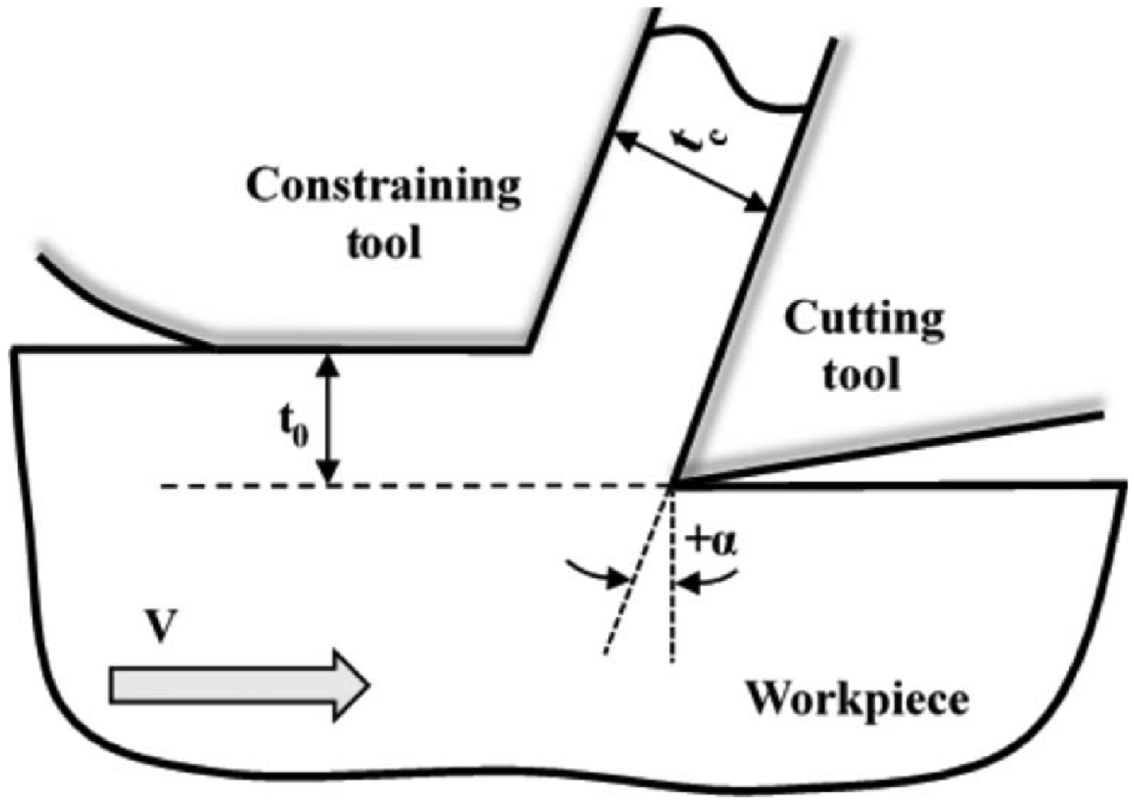
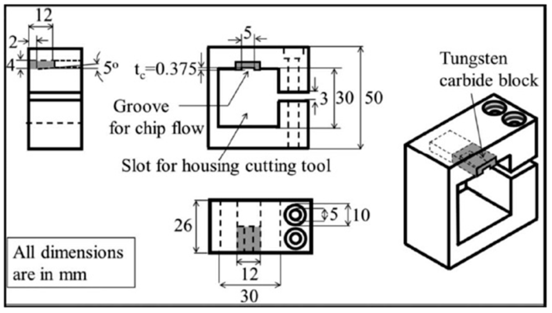
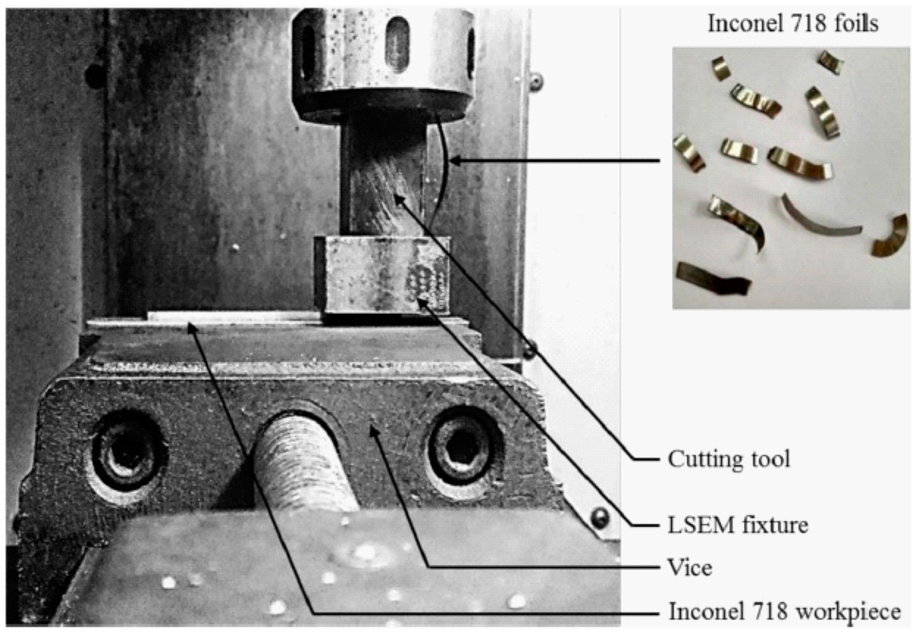
2.1. LSEM through Orthogonal Cutting

The basic functionality of both LSEM configurations remains the same. The only difference comes in the geometry of the machined chip. A schematic of the LSEM process through the orthogonal cutting procedure is shown in Figure 3. It consists of a cutting tool with a rake angle α and a constraining tool that controls the shape of the chip, which is being extruded with a thickness tc. This process is very similar to the orthogonal cutting process but with control over the shape and thickness of the chip. Gurusamy et al. [22] and Palaiappan et al. [23] conducted LSEM experiments through this method by using a Computer Numeric Control (CNC) milling machine with a custom-made tool and fixture for producing UFG chips of Inconel 718 and Ti-6Al-4V, respectively, as shown in Figure 4, Figure 5 and Figure 6.

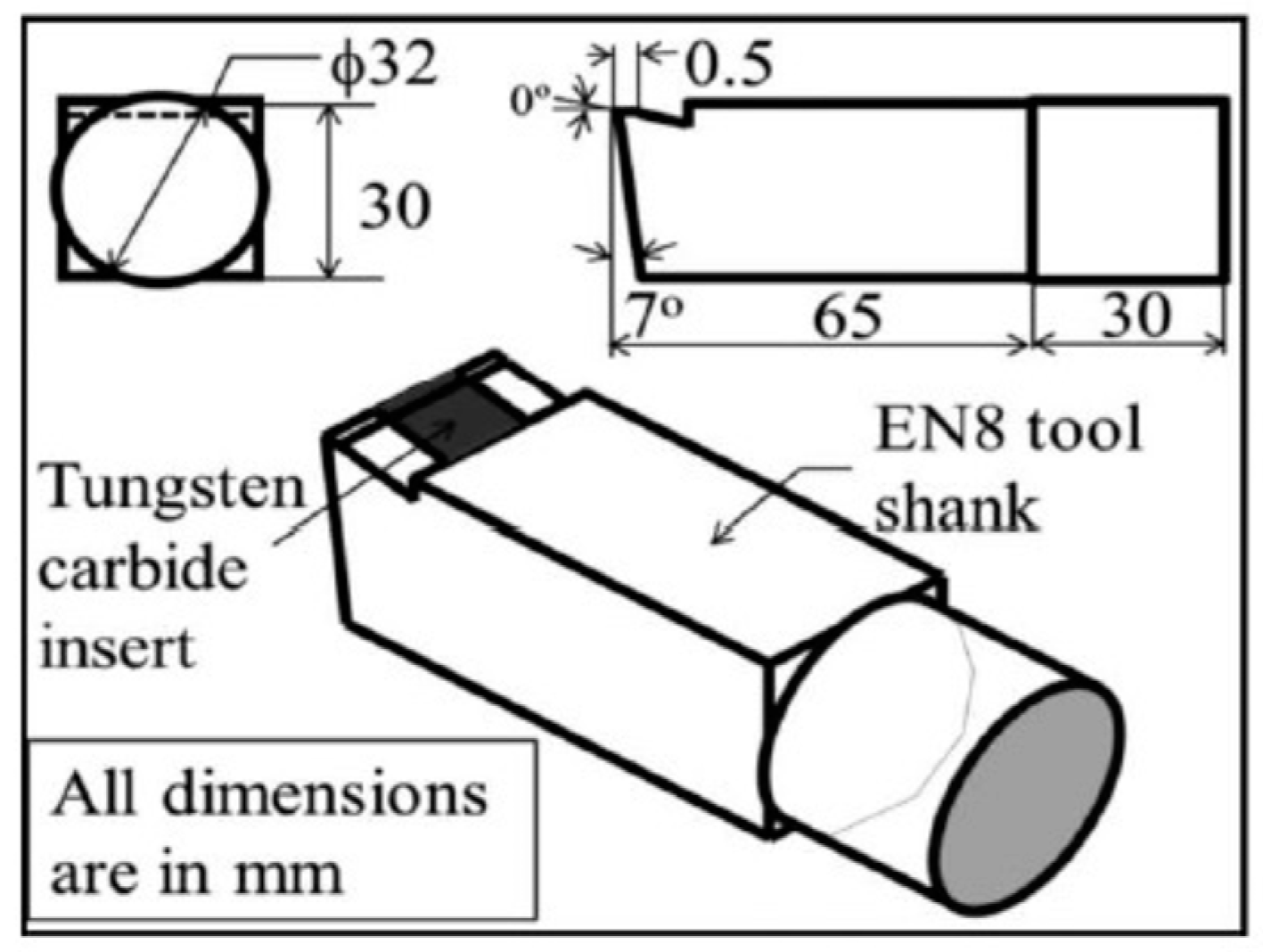
Cutting Tool and LSME Fixture

As shown in Figure 4 and Figure 5, a single-edge cutting tool and specially designed LSEM fixture were utilized for LSEM experiments by Palaniappan et al. [23]. Figure 5 provides details of the cutting tool utilized for the LSEM experiment with EN8 steel used for the tool shank, which is brazed to a Tungsten Carbide (WC-Co) insert with a defined rake and clearance angle of 0° and 7°. To avoid the effect of friction along the tool–chip interface, a restricted contact length of 0.5 mm is provided on the tungsten carbide insert, as shown in Figure 4 and Figure 5. Palaniappan et al. [23] designed an LSEM fixture specifically for orthogonal cutting, as per the dimensions shown in Figure 5. The LSEM fixture shown in Figure 5 has a tungsten carbide block of higher hardness brazed in the inner region where the chip extrudes. It helps avoid the erosion of the inner surface of the groove, as extrusion occurs due to the higher hardness of chip material compared to the EN8 utilized for manufacturing the LSEM fixture.
In our previous efforts [22,23], we were able to produce UFG foils of Ti-6Al-4V and Inconel 718 through LSEM experiments conducted using the orthogonal cutting approach. The extruded foils of Ti-6Al-4V and Inconel 718 had superior mechanical properties compared to the bulk material.

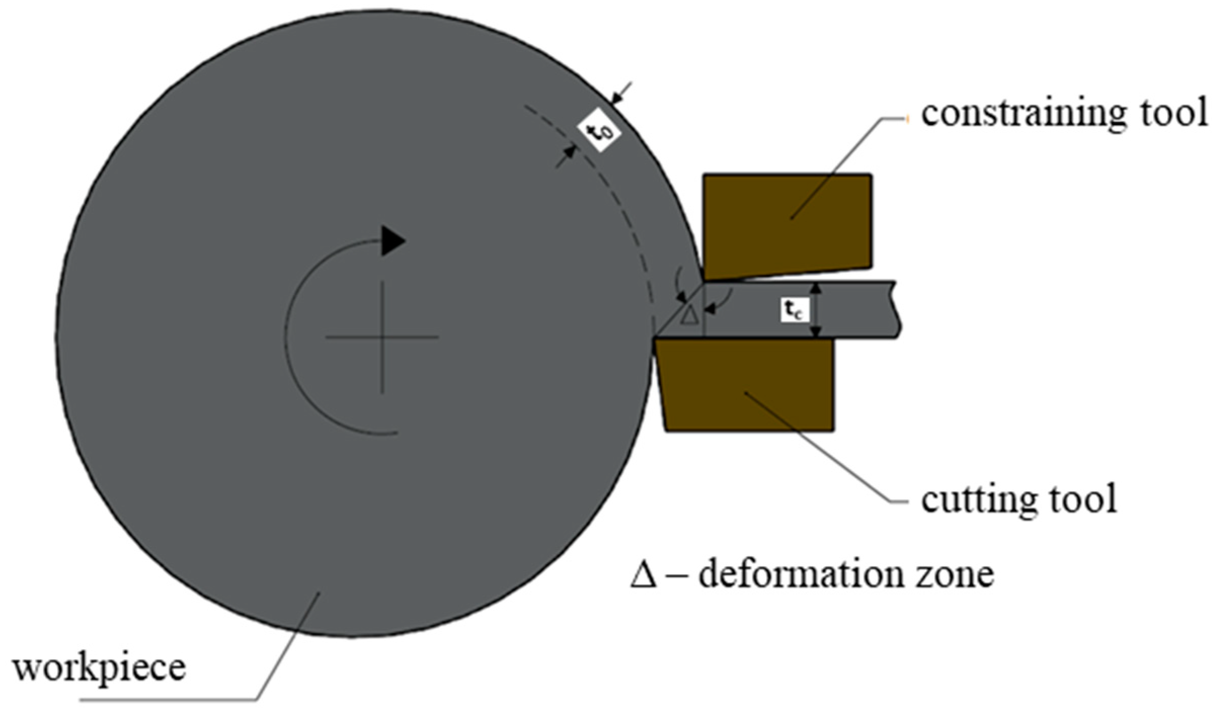
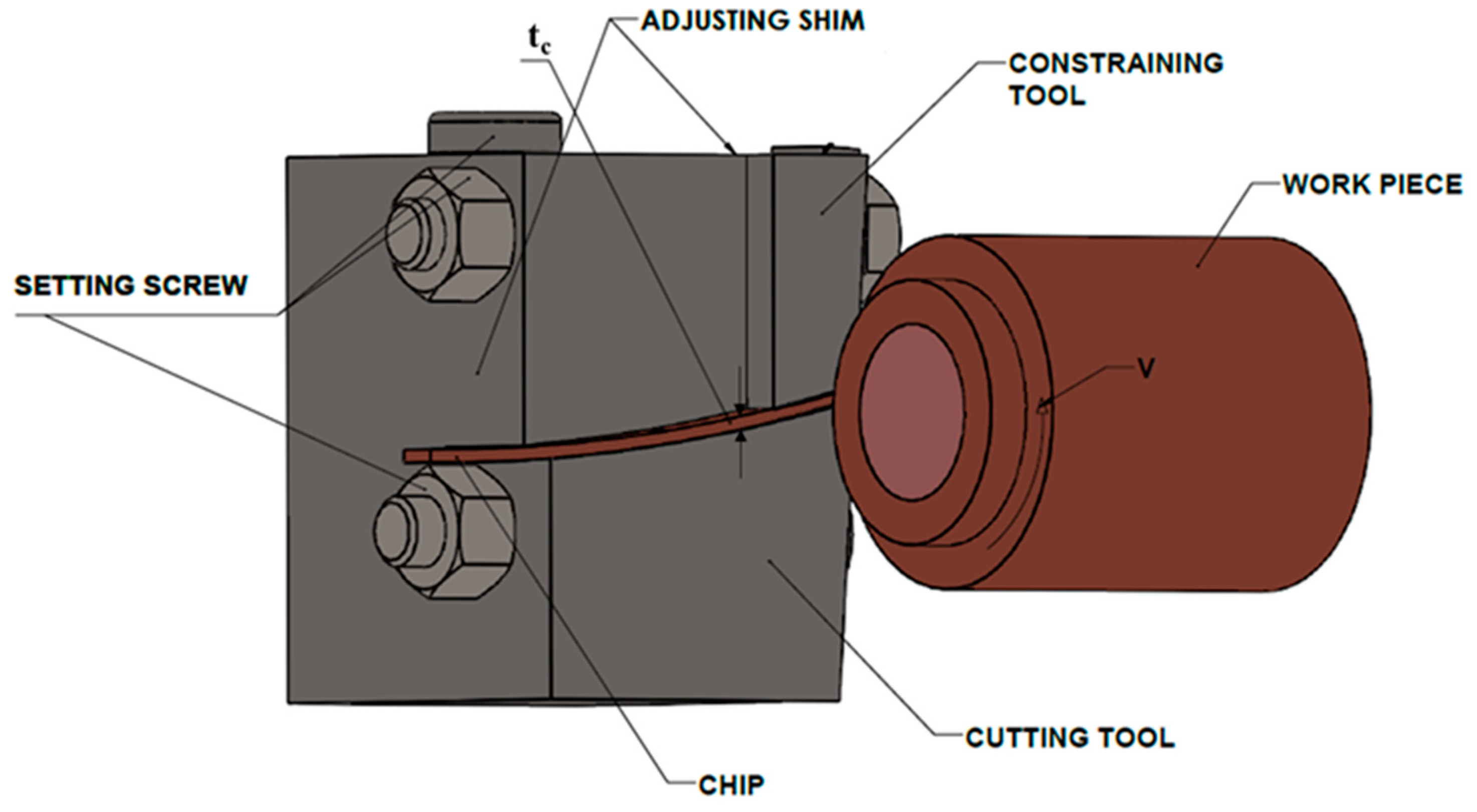
2.2. LSEM through Turning Experiment

The only limitation of LSEM through the orthogonal cutting configuration is that the continuous UFG strips or foils cannot be produced since the feed is restricted to the length of the workpiece. To overcome this shortcoming, a turning methodology is followed where the tool moves over a disc-shaped workpiece rotating at a constant speed V (m/s).
This setup also consists of two components, a single-point cutting tool with rake angle α and a wedge shape constraining part, as shown in Figure 7, which is made of a harder material. Because of the intense cutting pressure experienced during LSEM, the inner surface of the constraining part might be eroded. Hence, tungsten carbide inserts are brazed onto the inner side of the constraint tool or the whole constraining part should be made of a harder material similar to the cutting tool [23]. The tool radially advances at a constant feed rate t where the undeformed material is fed continuously in the machining zone. The velocity of the chip at the exit during the LSEM process is given by Vc = Vt0/tc, where tc is the cut chip thickness and t0 is the uncut chip thickness. Shear strain is purely dependent on rake angle α and chip thickness ratio (λ) where λ = tc/t0. Shear strain (γ) is given by,
γ = λ cos α + 1 λ cos α + 2 tan α
The turning experiment of LSEM is either carried out on hollow cylindrical tubes or solid cylindrical tubes [24,25,26]. Hollow tubes made of pure copper and solid tubes made of low-carbon steel are machined through the LSEM experimental setup, as shown in Figure 8 [27,28]. In the LSEM experimental setup shown in Figure 8, both cut and uncut chip thickness can be controlled by adjusting the screws provided. In order to minimize the effect of shear strain and temperature on the extruded chip, the cutting velocity is maintained at a low level [27,28].

2.3. Advantages of LSEM Process over Other SPD Processes

Equal-channel angular pressing (ECAP) is a conventional SPD process, as mentioned in Section 1, and it requires at least four passes to produce ultrafine-grain structures. In this regard, the time consumed by an ECAP process is higher compared to that of an LSEM process and, hence, the carbon footprint generated in ECAP is higher due to the larger machine run-time. In large-strain-extrusion machining, a single cut is enough for producing UFG foils or strips and, thus, reduces the energy consumption, which, in turn, translates to lesser carbon footprint deposition. In the LSEM process, UFG foils of different shapes with varying diameters can be achieved by modifying the fixture design. The nano-structured ribbons obtained from the LSEM process and other SPD have enhanced magnetic and electrical properties due to the assembly of organic structures. These UFG materials can be used in fabricating nanoelectromechanical systems (NEMSs) [25]. When the material is extruded in the shape of a wire or a rod, it can also be used as a core for multifunctional batteries. Machining of certain metals and alloys produces a shear localized chip, which, in turn, leads to larger tool wear, improper surface finish, and machine tool vibrations, which might lead to higher resource and energy consumption. Shear localization occurs when the rate of decrease in strength due to thermal softening exceeds the rate of increase in strength due to strain hardening. LSEM is a single-step plane-strain deformation process that combines large plastic strains of machining with a dimensional control of the chip due to extrusion. The chip is simultaneously forced to flow through the gap between the constraining edge and the rake surface of the cutting tool, thereby affecting the chip geometry to form a foil and, thus, helping to suppress shear localization. As a result, complete control of the deformation parameters, such as strain, strain rate, temperature, shape, and size of the grain, is possible through this combination of extrusion and machining processes [25].
Chatter is another important parameter to take into consideration when the quality of the finished product and energy consumed during machining are important. Serrated chips mostly give rise to vibrations, which might result in chatter. The LSEM process suppresses shear localization and produces continuous chips, which eventually ends up reducing the chatter [25].

3. LSEM of Various Metals and Alloys

LSEM is utilized for producing bulk UFG structures of various metals and alloys with enhanced physical and mechanical properties, such as hardness, wear resistance, and corrosion. Rolling is a commonly utilized metal forming process for producing high-strength materials through inducing a large amount of strain. However, it is a multi-stage process and it is also difficult to control the amount of strain and crystallographic texture during the deformation process, which is critical in deciding the behavior of the materials [29]. The LSEM process helps in producing ultrafine-grained materials with a controlled texture and, hence, it is adopted for producing fine-grained structures in several materials, such as copper, titanium, Ti-6Al-4V, Al6061-T6, Inconel 718, and many more [30,31]. In the following sections, LSEM process implementation for various metals and alloys is discussed in detail.

3.1. LSEM of Oxygen-Free High-Conductivity (OFHC) Copper, Pure Titanium, Tantalum, and Inconel 718

Moscoso et al. [16], Saldana et al. [32], and Yang et al. [33] implemented LSEM in both rotary and linear machining configurations to produce UFG materials in the form of continuous foil and sheets using various workpiece materials, such as OFHC copper (Cu), pure titanium (CP-Ti), tantalum (Ta), Al6061-T6, and Inconel 718. In our previous work [22], LSEM experiments were conducted in linear configuration using the Inconel 718 workpiece and were able to produce continuous foils of Inconel 718. Moscoso et al. [16] conducted a series of LSEM experiments with OFHC copper as a workpiece in the form of a disc on a conventional lathe. They conducted LSEM with chip compression ratios (λ) of 1.8, 4.2, 7.4, and 11 to realize shear strains in a range of 2 to 11. They also demonstrated LSEM as single-step SPD process for the production of nano-structured (OFHC) copper with greater control over the microstructure refinement by imposing varying levels of strain for a single rake angle (α) of 5°. Deng et al. [34] also conducted LSEM experiments using pure copper and analyzed the deformation-zone characteristics, such as strain, strain rate, and temperature distribution, using finite-element analysis.
Iglesias et al. [35] analyzed the tribological behavior of nano-structured OFHC copper and pure titanium and conducted a comparative study with coarse-grain counterparts. They found that microstructure refinement has no effect on friction but wear rates were lower for nano-structured copper and titanium in comparison to the coarse-grained samples. Pi et al. [36] studied the surface hardness and microstructure characteristics of pure copper strips produced through LSEM and found that they are dependent on chip thickness ratio, rake angle, and uncut chip thickness.

3.2. LSEM of MgAZ31B

Magnesium possesses a unique character of low density, reasonable strength, and good machinability and, hence, it is considered an alternative to aluminum and steel for building structures, especially automobile body panels. However, magnesium has poor workability and formability at room temperature due to its hexagonal close-packed crystal structure and, hence, is difficult to convert into sheets and foil form. In this regard, Efe et al. [21] and Sagapuram et al. [37] utilized the LSEM process for the successful continuous production of sheets and foils of a magnesium alloy, MgAZ31B, in a single-step deformation process under large deformation rates. Dong et al. [38] showed that the mechanical properties of the stretched-annealed form of extruded MgAZ31B sheets have a considerable improvement and also possess better formability. Liu et al. [39] explored the benefits of high-speed extrusion machining of a magnesium alloy, AZ31B, and observed an increase in Vicker’s hardness of extruded MgAZ31B sheets by 31% compared to the bulk form. Magnesium alloys have reduced corrosion resistance with respect to body fluids, limiting their use as biomedical implants. In this regard, Bertolini et al. [40] and Saffioti et al. [41] conducted LSEM of MgAZ31B under cryogenic cooling conditions, which enhanced the corrosion resistance behavior due to the formation of a fine-grain machined surface. Molafilabi et al. [42] investigated the LSEM process of pure magnesium with the help of both experimental and numerical studies and proposed optimal machining conditions for producing high-quality strips without any shear localization and fracture.

3.3. LSEM of Aluminium Alloys

Deng et al. [43] successfully produced strips of aluminum alloy (Al 6061) through the LSEM process conducted for a rotary machining configuration, as shown in Figure 8. Further, they also investigated the thermal stability of the UFG strips through extensive heat-treatment tests at different temperatures and found that UFG Al alloy chips were able to maintain their high hardness for annealing temperatures up to 200 °C and the hardness value started decreasing for temperatures greater than 300 °C. Aluminum 6xxx alloys subjected to heat treatment are widely utilized in the automotive industry due to their good formability, surface finish, and mechanical properties. In this regard, Bai et al. [44] implemented LSEM for an Al 6013 alloy as a single-step SPD process and were successful in producing continuous UFG strips. Among aluminum alloys, AA7050 is an aerospace-grade alloy because of its high strength but it is difficult to achieve uniform process control during the bulk forming process because of its complex structure. Klenosky [45] conducted LSEM of AA7050 and produced the bulk form of plates with properties similar to those seen in the conventional rolling process but with greater control over the process and, thus, eliminating defects in microstructure and properties. Yin et al. [46,47] investigated cryogenic-temperature large-strain-extrusion machining (CT-LSEM) as an SPD technique for fabricating UFG Al7075 sheets and found that with CT-LSEM, it is feasible to realize grain refinement and precipitation in an Al7075 alloy. Zhou et al. [26] studied the annealing temperature and time on the microstructure stability of a UFG Al6061 chip produced through the LSEM process and proposed a suitable annealing time and temperature, which does not cause a significant change in the grain size of UFG Al6061 chips. Sharma et al. [48] validated the LSEM capability for the Al6063 alloy and were able to successfully produce UFG Al6063 strips with an improvement in hardness of about 34 to 97% with respect to the bulk material. Yin et al. [49] and Chen et al. [50] investigated the effectiveness of cryogenic-temperature (CT) LSEM on Al 7075 in order to overcome the thermal softening effects observed during room-temperature (RT) LSEM. They observed that compared to RT LSEM, the Al 7075 foils produced using CT LSEM had better integrity and greater grain refinement. Further, Chen et al. [50] also observed that CT LSEM inhibits the formation of precipitation, thus, enhancing the formability of the material. Zhang et al. [51] also conducted CT LSEM to produce UFG copper strips, which were exhibiting better fretting wear properties compared to RT LSEM. Ping et al. [52] utilized finite element modelling to study the influence of tool geometry on the residual stress of the 7A04 aluminum alloy during LSEM. They found that varying the tool geometry had a significant impact on both the tensile and compressive residual stress distribution along the machined zone and continuous chips.

3.4. LSEM of Titanium Alloys

Ti-6Al-4V is a hard-to-machine titanium alloy, which is widely used in the aerospace industry for its superior mechanical properties and high strength-to-weight ratio. During normal unconstrained machining, the Ti-6Al-4V alloy gives rise to a shear localized chip, which leads to a cyclic cutting force, causing machine-tool vibrations, poor surface integrity, and rapid tool wear. Suppressing the shear localization will help in minimizing chatter, which would lead to improved tool-life and surface finish of the machined work piece. In this regard, Palaniappan et al. [23,53] demonstrated the suppression of shear localization through extrusion machining of cold-rolled Ti-6Al-4V plates in a milling machine setup with a similar cutting tool and LSEM fixture, as shown in Figure 6. Further, they also investigated the influence of initial texture and strain hardening on the deformation mechanism associated with the chip morphology during extrusion machining of Ti-6Al-4V. Wang et al. [54] studied the interconnection between the crystallographic texture and deformation history for the Ti-6Al-4V foils generated through the LSEM process in the rotary configuration, as shown in Figure 8, and concluded that the texture evolution during LSEM can be controlled by choosing the optimal cutting speed and chip-thickness ratio. Cai and Dai [55] conducted LSEM experiments on both Ti-6A-l4V and Inconel 718 alloys and demonstrated the transition from shear localized deformation to homogenous deformation at higher chip-thickness ratios. Bhardwaj et al. [56] utilized an SPD technique called constrained groove pressing (CGP) on Ti-6Al-4V plates and observed an enhancement in mechanical properties but, compared to LSEM, the CGP is a thermomechanical process conducted at constant elevated temperatures above 550 °C. Thus, CGP consumes more energy than the LSEM process.

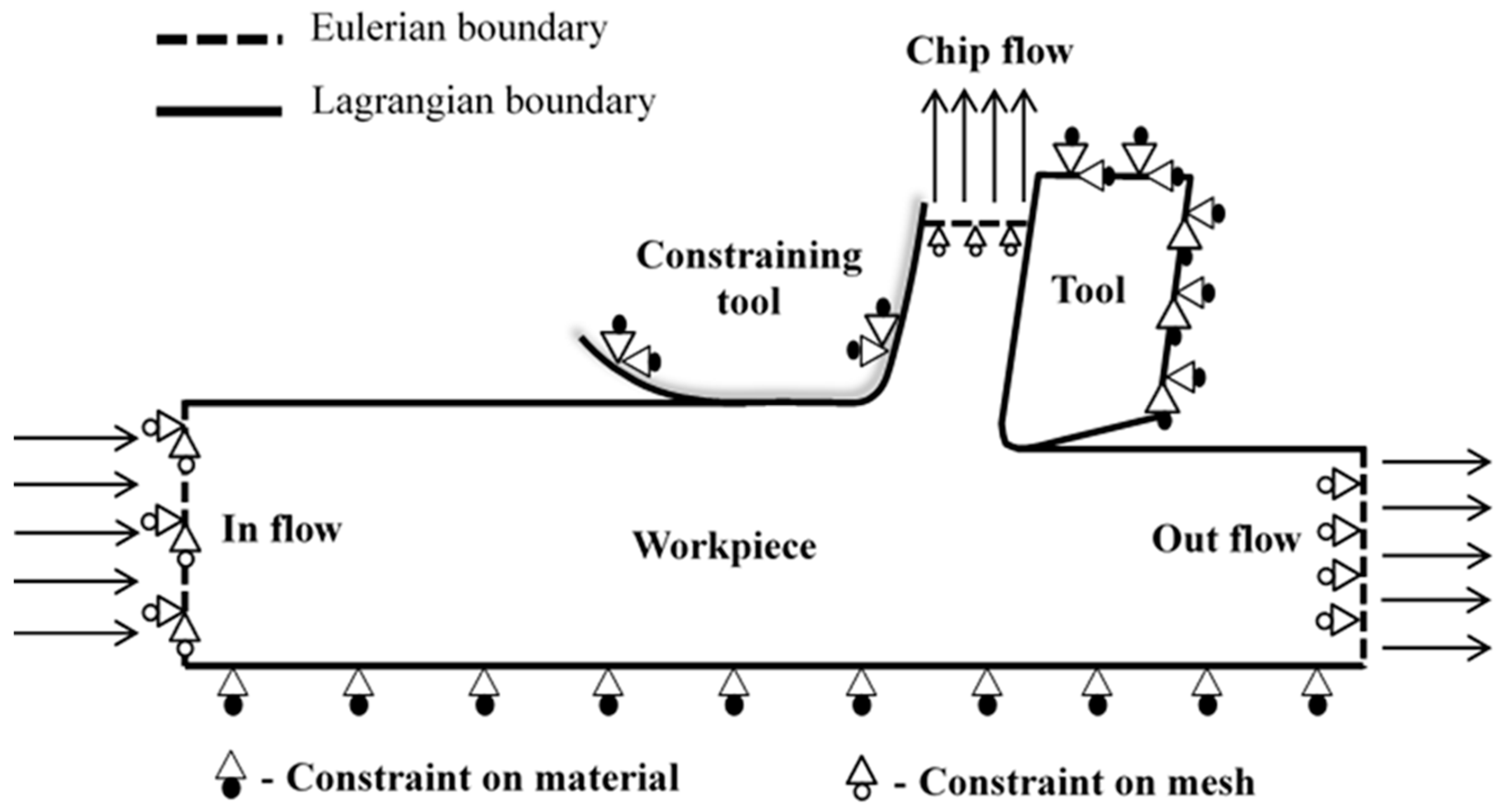
4. Finite-Element Modelling of Large-Strain-Extrusion Machining

In the literature, various studies have been carried out for finite-element (FE) modelling and the analysis of large-strain-extrusion machining of various metals and alloys. FE study helps in understanding the influence of various process parameters, such as cutting speed, chip compression ratio, and tool–chip interfacial friction on the deformation mechanism, chip morphology, strain, and strain rate distribution along the extruded chip. Further, the FE predictions will help in identifying the upper and lower limits of the chip compression ratio and, thus, it serves as a guideline in designing the LSEM setup for conducting optimal and accurate experiments. The different methodologies followed for developing the finite element model and procedure to analyze LSEM will be discussed in detail in the subsequent sections.

4.1. Geometric Description of the Finite-Element Model

The FE model in LSEM is modelled using various techniques. Sevier et al. [57] used an arbitrary Lagrangian and Eulerian (ALE) approach to model the orthogonal LSEM setup. In the ALE method, the LSEM setup is modelled using both Eulerian and Lagrangian boundaries and Sevier et al. [57] conducted their simulations in Abaqus/Explicit software. Deng et al. [24,27,34] and Pi et al. [58] followed a Lagrangian approach with continuous remeshing to model the orthogonal LSEM setup and they performed the simulation in Deform FE software. Lin et al. [59] also modelled the orthogonal configuration of LSEM as a Lagrangian model in order to study the effect of tool–chip interfacial friction on the deformation parameters. In our previous work [22], a coupled Eulerain and Lagrangian (CEL) approach was followed to model the LSEM setup, as shown in Figure 9.

4.2. Constitutive Model for Describing the Material Behaviour

The deformation mechanism encountered during LSEM is a function of strain hardening, strain-rate hardening, and thermal softening [18] and, hence, the constitutive model chosen to describe the material behavior during FE simulations should consider all the above-stated deformation-related parameters. Constitutive models are broadly classified based on the methodology followed for derivation and calibration of constants as empirical, semi-empirical, and physics-based models. Empirical models are derived and calibrated using empirical techniques, such as curve fitting, and they exhibit minimal flexibility but they are widely utilized because of the availability of constants for various materials [60]. Among empirical models, Johnson–Cook constitutive relation [61] is the most widely utilized model for simulating the material behavior during the machining process. The models that are derived based on the physics of deformation but with constants identified through empirical techniques are called semi-empirical models. Zerilli–Armstrong is the most widely adopted semi-empirical constitutive relation for finite-element modelling in the machining process [62,63]. Physics-based models are derived and calibrated based on the underlying physics through extensive experiments. These models are not widely utilized because they need a large number of experiments to calibrate more material constants than the empirical and semi-empirical models and, further, they have low computational efficiency [64]. To sum it up, the Johnson–Cook model has the advantages of simpler expression, availability of constants for various materials, and it is also embedded in much commercial FE software. However, the JC model does not consider the effects of strain, strain rate, and temperature, and also does not capture flow at high-strain values [65]. The ZA model has simple expression with fewer constants, and it also considers the effects of strain, strain rate, and temperature, but it is not widely embedded in FE software [65]. Finally, the physics-based model has limited use because of the difficulty faced in the calibration of constants.
LSEM is a modified form of the machining process and, hence, the deformation process characteristics are similar. Thus, the constitutive models used for the machining process are suitable for FE modeling in the LSEM process. Deng et al. [24,27,34] and Sevier et al. [57] modelled the material behavior as perfectly plastic, without considering the hardening effects and, thus, it does not entirely capture the real-time deformation process characteristics. However, in our previous effort [22], the material behavior was described using the proposed new modified Zerilli–Armstrong model, which is a physics-based constitutive relation incorporating all the deformation process phenomena. The FE simulations of LSEM reported in our previous effort are closer to reality since the physics underlying the deformation has been described through the constitutive model.

4.3. Damage Model

Damage refers to the microscopic defects that are generated due to the external process environment, which would influence the mechanical properties and further weaken the strength of the materials. The formulation of constitutive relation along with damage model formulation requires the integration of solid mechanics, failure theories, and continuum mechanics. A dynamic constitutive model considering the damage at a high strain rate is highly essential for FE modelling in the SPD process conducted at higher strain rate values [65]. The adiabatic shear localization is observed in a chip while machining difficult-to-deform materials at higher strain rates. Shear localization leads to uneven deformation and FE simulation requires damage models for these modes of deformation.
Gurson [66], Tvergaard, and Needleman [67,68,69] proposed the famous GTN (Gurson-Tvergaard-Needleman) damage constitutive model based on the concept coalescence of voids, which rapidly reduces the strength of materials. The GTN model is not suitable to describe under a triaxial state of stress and, hence, the Johnson and Cook damage model was proposed in order to overcome this limitation [65]. Cheng et al. [70] modified the JC model by adding a strain-softening term in order to capture the reduction in stress at higher strain values. Liu et al. [71] proposed an enhanced version of the ZA model by including the effects of material damage, such as micro-cracks and voids, during shear deformation. Calamaz et al. [72] included the temperature-softening term and proposed an improved JC model, namely the TANH model, in order to capture shear localization. A constitutive model developed considering the damage effects is required for capturing the real-time deformation during the FE simulation of metal cutting.

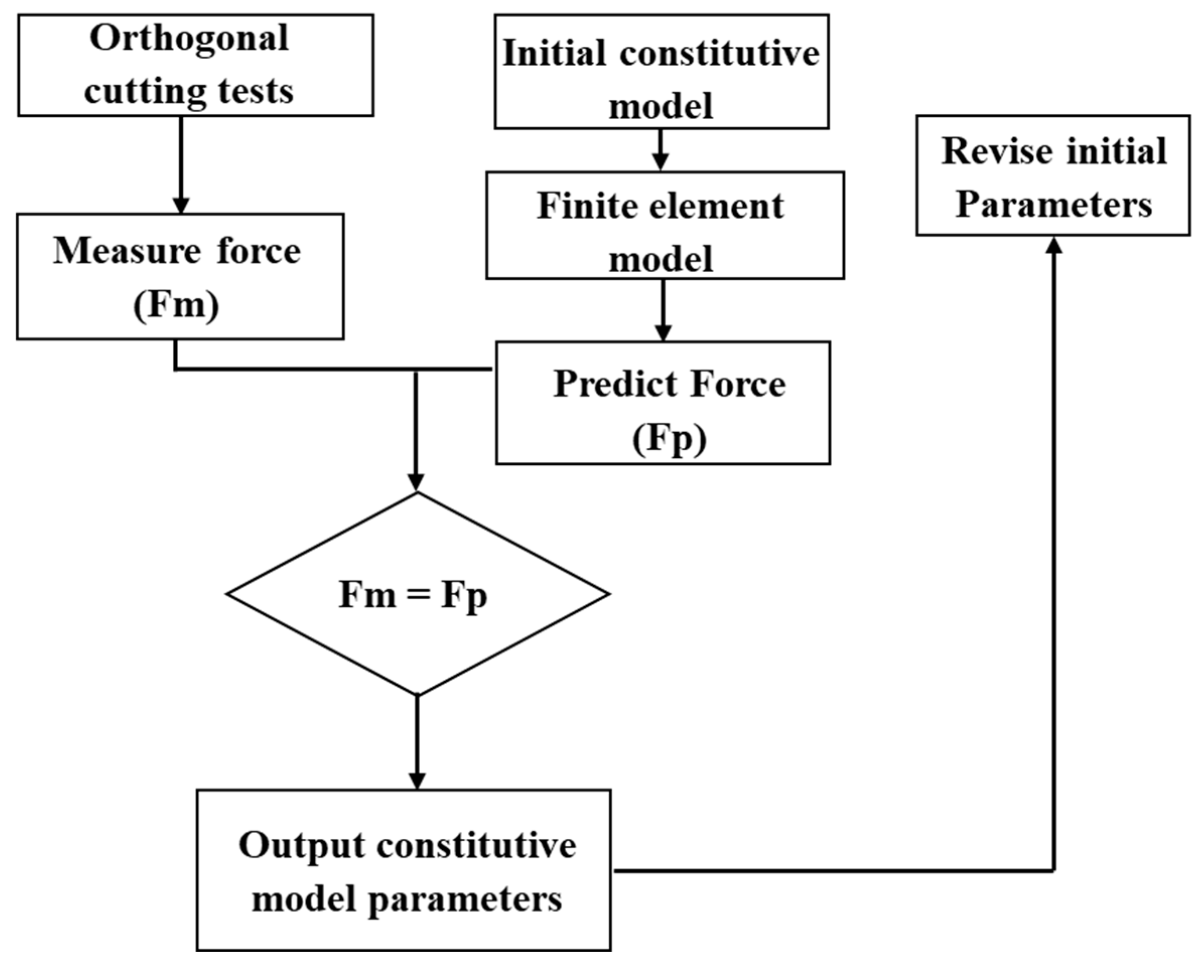
4.4. Material Parameter Identification for the Constitutive Model

Accurate parameter identification is necessary for the constitutive model to capture the real-time deformation phenomenon. Commonly used methods for calibrating the constitutive model are through mechanical testing experiments, Split Hopkinson Pressure Bar test (SHPB), metal-cutting experiments, and inverse methods. The constitutive data required for calibration have to be generated at the levels of strain and strain rate observed during the machining process, which is not possible using conventional material tests, such as tension and compression [73]. SPHB tests are widely used for studying material behavior under higher strain rates up to 105 s−1 but still, these are lower than that in machining (107 s−1). Hence, machining test data are required for the accurate calibration of a constitutive model but in situ measurements of strain, strain rate, and temperature during the machining process are difficult. In this regard, analytical formulations of the machining process, such as the Merchant and Oxley models, are used in conjunction with metal-cutting experiments to generate appropriate constitutive data for accurate calibration [73]. The inverse approach is another way to calibrate the constitutive model, where the finite simulations will be conducted with an initial guess of constants and are adjusted through comparing the experimental and predicted cutting forces until they become equal or the error is within a certain predefined limit [74,75]. A flow chart describing the inverse procedure for parameter identification is shown in Figure 10.

4.5. Availability of Constitutive Model Parameters

There is much research related to extracting dynamic mechanical properties of Ti-6Al-4V, but most efforts concentrated on calibrating the JC model. In this regard, Lee et al. [76], Meyer et al. [77], Seo et al. [78], and Zhou et al. [79] conducted different types of experiments at various strain rates, which are quite comparable to those observed during machining, and calibrated the JC parameter sets for Ti-6Al-4V.
AISI 1045 steel is a widely used material for fabricating various structural components. Various JC parameter sets for AISI 1045 calibrated using different methods are available in the literature. Naik et al. [80], Jaspers et al. [81], Bergs et al. [82], and He et al. [83] are some of the scholars who identified the JC parameters for AISI 1045 steel. Lee et al. [84] calibrated the JC model for AISI 4340 steel using SHPB tests and Sedighi et al. [85], used the Levenberg–Marquardt method to identify the constants in both the JC and ZA model for AISI 4340 steel.
It is observed that the JC and other similar constitutive relations have several different sets of parameters available in the literature for a single material, which is due to the dissimilarity in the initial condition of the material and the methodology utilized for calibration. Therefore, it is highly recommended to choose an appropriate set of constitutive model material parameters for accurate FE simulation in the metal-cutting process.

5. Applications of LSEM Process

The UFG and nano-crystalline materials exhibit superior mechanical, physical, and mechanical properties compared to the polycrystalline materials because of the presence of a larger grain boundary area and high-density defects. In this regard, various traditional SPD processes, such as equal-channel angular pressing (ECAP) [86,87], accumulative roll bending (ARB) [88,89], high-pressure torsion (HPT) [90], and twist extrusion (TE) [91], have been utilized for producing various UFG-class materials and alloys. Further, a new ECAP-based SPD technique called plastic flow machining (PFM) was proposed and demonstrated by Vu et al. [92,93] for producing UFG thin sheets of pure aluminum. PFM is a metal-forming process where a surface layer is separated from the workpiece due to plastic flow under high-compressive stresses [92,93]. As mentioned in Section 1, the LSEM process possesses various advantages compared to other SPD processes and, hence, it has been adopted widely for producing the bulk form of UFG materials for various metals and alloys. Further, with regard to cost, Iglesias et al. [94] conducted a preliminary cost analysis and reported that the production of UFG material through the LSEM process is less costly compared to other traditional SPD processes. Also, researchers have been successful in implementing LSEM for various metals and alloys, as reported in Section 3. Wu et al. [95] demonstrated the LSEM of pure copper and reported that UFG copper has superior thermal and mechanical properties. El-Atwani et al. [96] utilized LSEM to manufacture nanostructured HT-9 steel and also demonstrated the ability to control the microstructure through choosing appropriate LSEM conditions.
Moradi et al. [97] explored LSEM as a tool for producing a microstructure-refined fresh-machined surface, which could exhibit better surface integrity properties in fabricated components. Sagapuram et al. [98,99] demonstrated the usefulness of LSEM in controlling both microstructure refinement and texture development through a characterization study on an MgAZ31B sheet produced through LSEM. They found that LSEM helped in producing a combination of fine-grain structure and shear-based texture, which would have better formability compared to rolled sheets. Gigax et al. [100] were successful in producing a UFG equiatomic CrFeMnNi high-entropy alloy by subjecting it to various LSEM conditions. Sagapuram et al. [101] studied the deformation processing of a magnesium alloy subjected to LSEM and reported their findings related to flow transitions and flow localization, which would be of greater importance. Kumar et al. [102] performed both metallurgical and mechanical characterization studies on UFG titanium laminates produced through LSEM, which are also costly to manufacture using traditional SPD processes. Sagapuram et al. [103] demonstrated the application of LSEM using magnesium and titanium alloys for sheet production and also discussed its implications in saving a significant amount of material and energy in sheet processing.
There is strong demand for high-strength metallic materials with high strength to weight ratio for fabricating micro/meso-components and microelectromechanical devices. This demand is driven by the need for those micro-components to work in environments involving high temperature, large mechanical stresses, severe friction effects, corrosion, and subjection to high levels of radiation [104,105]. UFG and nano-structured materials with enhanced mechanical properties are preferred for micro-system applications since, in conventional micro-crystalline materials, the grain size is in the order of feature sizes in micro-system components, which is an undesirable mechanical condition [105]. In this regard, conventional SPD processes are widely utilized for the fabrication of bulk nanostructured materials from low- to moderate-strength alloys. However, LSEM has emerged as a popular alternative to the conventional SPD process because of its capability to perform SPD on difficult-to deform materials and also for its greater control over bulk geometry [106]. Saldana et al. [106] conducted LSEM on Inconel 718 and successfully produced UFG Inconel 718 foils and used these nano-structured materials as a precursor for conventional micro-machining or micro-forming processes to fabricate small-scale components. Thus, the combination of LSEM and a micro-machining process will help in fabricating 3D small-scale components for a broader group of nanostructured alloys.

6. LSEM as Frugal Process

The exploitation of Earth’s limited resources through human activities has led to a severe scarcity of resources and issues of climate change. In this regard, it is high time to adopt sustainability principles for all-round sustainable development, which would help in improving the standard of living and also allow the earth to prosper and be maintained [107]. Sustainable innovations are the need of the hour, as suggested by Boons et al. [108], for both economic and environmental upheaval. In this regard, advances in science and technology are required for frugal manufacturing, which will reduce cost and resource consumption [109]. Frugality through resource optimization is an important pillar for sustainable development [110]. Rao [111] examined the disruptive nature of frugal innovations by studying various examples of frugal innovations in different sectors. The frugal products are manufactured with minimal resources at low cost but they exhibit better functionalities compared to conventional types and, in recent years, they have started proliferating the market, which is a sign of moving towards sustainable development [112,113,114,115,116]. The manufacturing process plays an important role by providing proper inputs to frugal design and, further, for the fabrication of frugal products. Therefore, there is a need to conceptualize and implement a frugal manufacturing process [117]. Rao [118] defined the concept of frugal manufacturing as a fabrication activity utilizing a minimal number of processes at low cost without any compromise on surface integrity and other appropriate properties.
Mann et al. [119] studied the demonstrated capabilities of the LSEM process and proposed that it is an attractive machining-based process for producing bulk forms, such as foils, sheets, wires, and strips, in a low-cost energy-efficient method because of its characteristic features. LSEM, as single-step SPD process, has the capability to produce bulk forms of sheet, foil, strip, and wire, even from low-machinability alloys with varying UFG microstructure and crystallographic texture using a compact and economical infrastructure. Therefore, LSEM could be considered as a frugal manufacturing process since it helps in reducing waste through recycling the chip and it is also a single-step energy-efficient process.

7. Conclusions Remarks

The present review paper provides a deeper understanding regarding the need, development, capabilities, and current status of LSEM, which is a modified form of the conventional machining process. The review also reveals the various advantages of LSEM compared to various SPD processes by providing information regarding the implementation of LSEM for various metals and alloys. The article also helps researchers with information related to the design of the LSEM experimental setup and optimal cutting conditions for successfully conducting experiments to produce UFG forms of their choice of materials. LSEM has emerged as an attractive alternative to conventional SPD processes because of its inherent advantages, listed below:
  • It exhibits greater control over bulk geometry;
  • It helps in generating a variety of nano-scale microstructures by varying the deformation conditions, which is carried out easily by implementing different cutting parameters;
  • It helps in engineering the surface of the components with required micro- or nano-scale structures;
  • It is energy efficient compared to conventional SPD processes because of single-step processing;
  • It can be utilized for fabricating nano-structured materials from low-, medium-, and high-strength metals and alloys;
  • It can be used to meet the stronger demand for nanostructured materials for fabricating micro-scale components;
  • LSEM is a sustainable machining process since it transforms the chip from being a waste to a more usable bulk form for other meaningful purposes;
  • LSEM is an attractive frugal manufacturing process for fabricating frugal products.
Thus, the detailed review presented in this article helps us to understand the evolution and relevance of LSEM as a sustainable SPD process. The review also helps researchers with various information regarding the LSEM process, which they might exploit for their future study in establishing the process capabilities related to various other materials and application areas.

Author Contributions

Conceptualization, M.G. and B.C.R.; methodology, M.G.; validation, M.G.; formal analysis, M.G.; investigation, M.G.; data curation, M.G.; writing—original draft preparation, M.G.; writing—review and editing, M.G. and B.C.R.; visualization, M.G. and B.C.R.; supervision, B.C.R.; project administration, B.C.R. All authors have read and agreed to the published version of the manuscript.

Funding

This research received no external funding.

Data Availability Statement

No datasets were generated during the current study.

Conflicts of Interest

The authors declare no conflict of interest.

References

  1. Gleiter, H. Nanostructured materials: Basic concepts and microstructure. Acta Mater. 2000, 48, 1–29. [Google Scholar] [CrossRef] [Green Version]
  2. Siegel, R.W. Creating Nanophase Material. Sci. Am. 1996, 275, 74. [Google Scholar] [CrossRef]
  3. Nieman, G.W.; Weertman, J.R.; Siegel, R.W. Mechanical behavior of nanocrystalline Cu and Pd. J. Mater. Res. 1991, 6, 1012–1027. [Google Scholar] [CrossRef] [Green Version]
  4. Birringer, R. Nanocrystalline materials. Mater. Sci. Eng. A 1989, 117, 33–43.6. [Google Scholar] [CrossRef]
  5. Lu, L.; Sui, M.L.; Lu, K. Superplastic extensibility of nanocrystalline copper at room temperature. Science 2000, 287, 1463–1466. [Google Scholar] [CrossRef] [PubMed]
  6. McFadden, S.X.; Mishra, R.S.; Valiev, R.Z.; Zhilyaev, A.P.; Mukherjee, A.K. Low-temperature superplasticity in nanostructured nickel and metal alloys. Nature 1999, 398, 684–686. [Google Scholar] [CrossRef]
  7. Langford, G.; Cohen, M. Strain hardening of iron by severe plastic deformation. ASM Trans. Quart 1969, 62, 623–638. [Google Scholar]
  8. Valiev, R.Z.; Islamgaliev, R.K.; Alexandrov, I.V. Bulk nanostructured materials from severe plastic deformation. Prog. Mater. Sci. 2000, 45, 103–189. [Google Scholar] [CrossRef]
  9. Humphreys, F.J.; Prangnell, P.B.; Bowen, J.R.; Gholinia, A.; Harris, C. Developing stable fine–grain microstructures by large strain deformation. Philos. Trans. R. Soc. Lond. Ser. A Math. Phys. Eng. Sci. 1999, 357, 1663–1681. [Google Scholar] [CrossRef]
  10. Segal, V.M.; Reznikov, V.I.; Drobyshevskiy, A.E.; Kopylov, V.I. Plastic Working of Metals by Simple Shear. Russ. Metall. 1981, 1, 99–105. [Google Scholar]
  11. Brown, T.; Swaminathan, S.; Chandrasekar, S.; Compton, W.; King, A.; Trumble, K. Low-cost manufacturing process for nanostructured metals and alloys. J. Mater. Res. 2002, 17, 2484–2488. [Google Scholar] [CrossRef]
  12. Gurusamy, M.; Rao, B. A new constitutive relation for simulating plastic flow involving continuous-shear or shear-localisation during metal cutting. Philos. Mag. 2020, 100, 486–511. [Google Scholar] [CrossRef]
  13. Merchant, M.E. Mechanics of the metal cutting process. II. Plasticity conditions in orthogonal cutting. J. Appl. Phys. 1945, 16, 318–324. [Google Scholar] [CrossRef]
  14. Shaw, M.C. Metal Cutting Principles; Clarendon: Oxford, UK, 1984; p. 32. [Google Scholar]
  15. Swaminathan, S.; RaviShankar, M.; Lee, S.; Hwang, J.; King, A.H.; Kezar, R.F.; Rao, B.C.; Brown, T.L.; Chandrasekar, S.; Compton, W.D.; et al. Large Strain Deformation and Ultrafine Grained Materials by Machining. Mater. Sci. Eng. A 2005, 410–411, 358–363. [Google Scholar] [CrossRef]
  16. Moscoso, W.; Ravi Shankar, M.; Mann, J.B.; Compton, W.D.; Chandrasekar, S. Bulk Nanostructured Materials by Large Strain Extrusion Machining. J. Mater. Res. 2007, 22, 201–205. [Google Scholar] [CrossRef]
  17. Liu, Y.; Cai, S.; Xu, F.; Wang, Y.; Dai, L. Enhancing strength without compromising ductility in copper by combining extrusion machining and heat treatment. J. Mater. Process. Technol. 2019, 267, 52–60. [Google Scholar] [CrossRef] [Green Version]
  18. Cai, S.L.; Chen, Y.; Ye, G.G.; Jiang, M.Q.; Wang, H.Y.; Dai, L.H. Characterization of the deformation field in large-strain extrusion machining. J. Mater. Process. Technol. 2015, 216, 48–58. [Google Scholar] [CrossRef]
  19. Guo, Y.A.N.G.; Efe, M.; Moscoso, W.; Sagapuram, D.; Trumble, K.P.; Chandrasekar, S. Deformation field in large-strain extrusion machining and implications for deformation processing. Scr. Mater. 2012, 66, 235–238. [Google Scholar] [CrossRef]
  20. Guo, Y.; Chen, J.; Saleh, A. In situ analysis of deformation mechanics of constrained cutting toward enhanced material removal. J. Manuf. Sci. Eng. 2020, 142, 021002. [Google Scholar] [CrossRef]
  21. Efe, M.; Moscoso, W.; Trumble, K.P.; Compton, W.D.; Chandrasekar, S. Mechanics of large strain extrusion machining and application to deformation processing of magnesium alloys. Acta Mater. 2012, 60, 2031–2042. [Google Scholar] [CrossRef]
  22. Gurusamy, M.; Palaniappan, K.; Murthy, H.; Rao, B.C. A Finite Element Study of Large Strain Extrusion Machining Using Modified Zerilli–Armstrong Constitutive Relation. J. Manuf. Sci. Eng. 2021, 143, 101004. [Google Scholar] [CrossRef]
  23. Palaniappan, K.; Murthy, H.; Rao, B.C. Production of fine-grained foils by large strain extrusion-machining of textured Ti–6Al–4V. J. Mater. Res. 2018, 33, 108–120. [Google Scholar] [CrossRef]
  24. Deng, W.J.; Lin, P.; Li, Q.; Xia, W. Effect of constraining tool corner radius on large strain extrusion machining. Mater. Manuf. Process. 2013, 28, 1090–1094. [Google Scholar] [CrossRef]
  25. Moscoso, W. Severe Plastic Deformation and Nanostructured Materials by Large Strain Extrusion Machining. Ph.D. Thesis, Purdue University, West Lafayette, IN, USA, 2008. [Google Scholar]
  26. Zhou, Z.; Wu, B.; Chen, H.; Zhang, B.; Deng, W. Microstructure evolution of ultrafine grained aluminum alloy prepared by large strain extrusion machining during annealing. Mater. Res. Express 2019, 6, 116550. [Google Scholar] [CrossRef]
  27. Deng, W.J.; He, Y.T.; Lin, P.; Xia, W.; Tang, Y. Investigation of the effect of rake angle on large strain extrusion machining. Mater. Manuf. Process. 2014, 29, 621–626. [Google Scholar] [CrossRef]
  28. Zhang, J.Y.; Li, B.L.; Zou, Z.J.; Zou, T.; Deng, W.J. Grain refinement and thermal stability of AISI1020 strips prepared by large strain extrusion machining. In Materials Science Forum; Trans Tech Publications Ltd.: Bäch, Switzerland, 2016; Volume 836, pp. 509–521. [Google Scholar]
  29. Kumar, P.; Joshi, R.S.; Singla, R.K. Sliding wear behaviour of CP titanium laminates produced by large strain extrusion machining. Wear 2021, 477, 203774. [Google Scholar] [CrossRef]
  30. Swaminathan, S.; Shankar, M.R.; Rao, B.; Compton, W.; Chandrasekar, S.; King, A.; Trumble, K. Severe plastic deformation (SPD) and nanostructured materials by machining. J. Mater. Sci. 2007, 42, 1529–1541. [Google Scholar] [CrossRef]
  31. Iglesias, M.D.; Bermúdez, W.; Moscoso, S. Chandrasekar, Influence of processing parameters on wear resistance of nanostructured OFHC copper manufactured by large strain extrusion machining. Wear 2010, 268, 178–184. [Google Scholar] [CrossRef]
  32. Saldana, C.; Swaminathan, S.; Brown, T.L.; Moscoso, W.; Mann, J.B.; Compton, W.D.; Chandrasekar, S. Unusual applications of machining: Controlled nanostructuring of materials and surfaces. J. Manuf. Sci. Eng. 2010, 132, 030908. [Google Scholar] [CrossRef]
  33. Yang, P.; Buchheit, T.E.; Gill, D.D.; Saldana, C.J.; Chandrasekar, S. Fabrication of Nanostructured Inconel 718 Alloys by Large Strain Extrusion Machining (No. SAND2007-6491C); Sandia National Lab (SNL-NM): Albuquerque, NM, USA, 2007. [Google Scholar]
  34. Deng, W.J.; Lin, P.; Xie, Z.C.; Li, Q. Analysis of large-strain extrusion machining with different chip compression ratios. J. Nanomater. 2012, 2012, 93. [Google Scholar] [CrossRef] [Green Version]
  35. Iglesias, P.; Bermudez, M.D.; Moscoso, W.; Rao, B.C.; Shankar, M.R.; Chandrasekar, S. Friction and wear of nanostructured metals created by large strain extrusion machining. Wear 2007, 263, 636–642. [Google Scholar] [CrossRef]
  36. Pi, Y.; Yin, X.; Deng, W.; Xia, W. Study on Surface Hardness and Microstructure of Pure Copper Chip Strips Prepared by LSEM. Adv. Mater. Sci. Eng. 2019, 2019, 5254892. [Google Scholar] [CrossRef]
  37. Sagapuram, D.; Efe, M.; Moscoso, W.; Chandrasekar, S.; Trumble, K.P. Deformation temperature effects on microstructure and texture evolution in high strain rate extrusion-machining of Mg-AZ31B. In Materials Science Forum; Trans Tech Publications Ltd.: Bäch, Switzerland, 2012; Volume 702, pp. 52–55. [Google Scholar]
  38. Dong, J.; Zhang, D.; Dong, Y.; Chai, S.; Pan, F. Microstructure evolution and mechanical response of extruded AZ31B magnesium alloy sheet at large strains followed by annealing treatment. Mater. Sci. Eng. A 2014, 618, 262–270. [Google Scholar] [CrossRef]
  39. Liu, Y.; Cai, S.; Dai, L. A new method for grain refinement in magnesium alloy: High speed extrusion machining. Mater. Sci. Eng. A 2016, 651, 878–885. [Google Scholar] [CrossRef] [Green Version]
  40. Bertolini, R.; Bruschi, S.; Ghiotti, A. Large strain extrusion machining under cryogenic cooling to enhance corrosion resistance of magnesium alloys for biomedical applications. Procedia Manuf. 2018, 26, 217–227. [Google Scholar] [CrossRef]
  41. Saffioti, M.R.; Bertolini, R.; Umbrello, D.; Ghiotti, A.; Bruschi, S. Experimental and Numerical Investigation Of Large Strain Extrusion Machining Of AZ31 Magnesium Alloy For Biomedical Applications. Procedia CIRP 2022, 110, 36–40. [Google Scholar] [CrossRef]
  42. Molafilabi, S.; Sadeghi, A.; Hadad, M. Investigation of large strain extrusion machining (LSEM) of pure magnesium (Mg). Int. J. Lightweight Mater. Manuf. 2020, 3, 100–107. [Google Scholar] [CrossRef]
  43. Deng, W.J.; Li, Q.; Li, B.L.; Xie, Z.C.; He, Y.T.; Tang, Y.; Xia, W. Thermal stability of ultrafine grained aluminium alloy prepared by large strain extrusion machining. Mater. Sci. Technol. 2014, 30, 850–859. [Google Scholar] [CrossRef]
  44. Bai, X.; Kustas, A.; Chandrasekar, S.; Trumble, K. Large strain extrusion machining on 6013 aluminum alloy. In Light Metals; Springer: Cham, Switzerland, 2016; pp. 225–229. [Google Scholar]
  45. Klenosky, D.R. Large Strain Extrusion Machining of AA7050. Ph.D. Thesis, Purdue University, West Lafayette, IN, USA, 2018. [Google Scholar]
  46. Yin, X.; Chen, H.; Deng, W. Effects of machining velocity on ultrafine grained al 7075 alloy produced by cryogenic temperature large strain extrusion machining. Materials 2019, 12, 1656. [Google Scholar] [CrossRef] [PubMed] [Green Version]
  47. Yin, X.; Deng, W.; Zou, Y.; Zhang, J. Ultrafine grained Al 7075 alloy fabricated by cryogenic temperature large strain extrusion machining combined with aging treatment. Mater. Sci. Eng. A 2019, 762, 138106. [Google Scholar] [CrossRef]
  48. Sharma, V.K.; Kumar, V.; Singh Joshi, R. Quantitative analysis of microstructure refinement in ultrafine-grained strips of Al6063 fabricated using large strain extrusion machining. Mach. Sci. Technol. 2020, 24, 42–64. [Google Scholar] [CrossRef]
  49. Yin, X.; Pi, Y.; He, D.; Zhang, J.; Deng, W. Development of ultrafine grained Al 7075 by cryogenic temperature large strain extrusion machining. J. Mater. Res. 2018, 33, 3449–3457. [Google Scholar] [CrossRef]
  50. Chen, H.; Zhang, B.; Zhang, J.; Deng, W. Preparation of Ultrafine-Grained Continuous Chips by Cryogenic Large Strain Machining. Metals 2020, 10, 398. [Google Scholar] [CrossRef] [Green Version]
  51. Zhang, B.; Zeng, Y.; Pang, X.; Deng, W. Fretting wear behaviour of ultrafine-grained copper produced by cryogenic temperature extrusion machining. Mater. Sci. Technol. 2022, 1–10. [Google Scholar] [CrossRef]
  52. Ping, Z.; Penghao, W.; Xiujie, Y.; Yanchun, Z.; Xiao, Y. Influence of tool geometric parameters on the residual stress of 7A04 aluminum alloy in LSEM. Int. J. Adv. Manuf. Technol. 2022, 120, 1707–1728. [Google Scholar] [CrossRef]
  53. Palaniappan, K.; Sundararaman, M.; Murthy, H.; Jeyaraam, R.; Rao, B.C. Influence of workpiece texture and strain hardening on chip formation during machining of Ti–6Al–4V alloy. Int. J. Mach. Tools Manuf. 2022, 173, 103849. [Google Scholar] [CrossRef]
  54. Wang, Q.; Shankar, R.M.; Liu, Z.; Cheng, Y. Crystallographic texture evolutions of Ti-6Al-4V chip foils in relation to strain path and high strain rate arising from large strain extrusion machining process. J. Mater. Process. Technol. 2022, 305, 117588. [Google Scholar] [CrossRef]
  55. Cai, S.L.; Dai, L.H. Suppression of repeated adiabatic shear banding by dynamic large strain extrusion machining. J. Mech. Phys. Solids 2014, 73, 84–102. [Google Scholar] [CrossRef]
  56. Bhardwaj, A.; Gohil, N.; Gupta, A.K.; Kumar, S.S. An experimental investigation on the influence of elevated-temperature constrained groove pressing on the microstructure, mechanical properties and hardening behaviour of Ti-6Al-4V alloy. Mater. Sci. Eng. A 2021, 802, 140651. [Google Scholar] [CrossRef]
  57. Sevier, M.; Yang, H.T.Y.; Moscoso, W.; Chandrasekar, S. Analysis of severe plastic deformation by large strain extrusion machining. Metall. Mater. Trans. A 2008, 39, 2645–2655. [Google Scholar] [CrossRef]
  58. Pi, Y.Y.; Deng, W.J.; Zhang, J.Y.; Yin, X.L.; Xia, W. Towards understanding the microstructure and temperature rule in large strain extrusion machining. Adv. Manuf. 2021, 9, 262–272. [Google Scholar] [CrossRef]
  59. Lin, P.; Xie, Z.C.; Li, Q. Effect of the friction coefficient on large strain extrusion machining. In Applied Mechanics and Materials; Trans Tech Publications Ltd.: Bäch, Switzerland, 2013; Volume 273, pp. 138–142. [Google Scholar]
  60. Lin, Y.C.; Chen, X.M. A critical review of experimental results and constitutive descriptions for metals and alloys in hot working. Mater. Des. 2011, 32, 1733–1759. [Google Scholar] [CrossRef]
  61. Johnson, G.R.; Cook, W.H. A constitutive model and data for metals subjected to large strain, high strain rates and high temperatures. In Proceedings of the 7th International Symposium on Ballistics, Hague, The Netherlands, 19–21April 1983; pp. 541–547. [Google Scholar]
  62. Shi, J.; Liu, C.R. The influence of material models on finite element simulation of machining. J. Manuf. Sci. Eng. 2004, 126, 849–857. [Google Scholar] [CrossRef]
  63. Zerilli, F.J.; Armstrong, R.W. Dislocation-mechanics-based constitutive relations for material dynamics calculations. J. Appl. Phys. 1987, 61, 1816–1825. [Google Scholar] [CrossRef] [Green Version]
  64. Khan, A.S.; Suh, Y.S.; Kazmi, R. Quasi-static and dynamic loading responses and constitutive modeling of titanium alloys. Int. J. Plast. 2004, 20, 2233–2248. [Google Scholar] [CrossRef]
  65. Sun, Y.; Li, G.; He, Z.; Kong, X. The advance of research on constitutive model used in finite element simulation of metal cutting. Proc. Inst. Mech. Eng. Part C J. Mech. Eng. Sci. 2022, 236, 4921–4945. [Google Scholar] [CrossRef]
  66. Gurson, A.L. Plastic Flow and Fracture Behavior of Ductile Materials Incorporating Void Nucleation, Growth, and Interaction. Ph.D. Thesis, Brown University, Providence, RI, USA, 1977. [Google Scholar]
  67. Tvergaard, V. Influence of voids on shear band instabilities under plane strain conditions. Int. J. Fract. 1981, 17, 389–407. [Google Scholar] [CrossRef]
  68. Tvergaard, V. On localization in ductile materials containing spherical voids. Int. J. Fract. 1982, 18, 237–252. [Google Scholar] [CrossRef]
  69. Chu, C.C.; Needleman, A. Void nucleation effects in biaxially stretched sheets. J. Eng. Mater. Technol. 1980, 102, 249–256. [Google Scholar] [CrossRef]
  70. Cheng, G.Q.; Li, S.X. A damage related thermo-viscoplastic constitutive model of metallic materials under high rate deformation. Mater. Sci. Technol. 2005, 21, 813–816. [Google Scholar] [CrossRef]
  71. Liu, R.; Melkote, S.; Pucha, R.; Morehouse, J.; Man, X.; Marusich, T. An enhanced constitutive material model for machining of Ti–6Al–4V alloy. J. Mater. Process. Technol. 2013, 213, 2238–2246. [Google Scholar] [CrossRef]
  72. Calamaz, M.; Coupard, D.; Girot, F. A new material model for 2D numerical simulation of serrated chip formation when machining titanium alloy Ti–6Al–4V. Int. J. Mach. Tools Manuf. 2008, 48, 275–288. [Google Scholar] [CrossRef]
  73. Childs, T.H.C. Material property needs in modeling metal machining. Mach. Sci. Technol. 1998, 2, 303–316. [Google Scholar] [CrossRef]
  74. Shrot, A.; Bäker, M. Inverse identification of Johnson-Cook material parameters from machining simulations. In Advanced Materials Research; Trans Tech Publications Ltd.: Bäch, Switzerland, 2011; Volume 223, pp. 277–285. [Google Scholar]
  75. Bäker, M.; Shrot, A. Inverse parameter identification with finite element simulations using knowledge-based descriptors. Comput. Mater. Sci. 2013, 69, 128–136. [Google Scholar] [CrossRef]
  76. Lee, W.S.; Lin, C.F. High-temperature deformation behaviour of Ti-6Al-4V alloy evaluated by high strain-rate compression tests. J. Mater. Process. Technol. 1998, 75, 127–136. [Google Scholar] [CrossRef]
  77. Meyer Jr, H.W.; Kleponis, D.S. Modeling the high strain rate behavior of titanium undergoing ballistic impact and penetration. Int. J. Impact Eng. 2001, 26, 509–521. [Google Scholar] [CrossRef]
  78. Seo, S.; Min, O.; Yang, H. Constitutive equation for Ti–6Al–4V at high temperatures measured using the SHPB technique. Int. J. Impact Eng. 2005, 31, 735–754. [Google Scholar] [CrossRef]
  79. Zhou, T.; Wu, J.; Che, J.; Wang, Y.; Wang, X. Dynamic shear characteristics of titanium alloy Ti-6Al-4V at large strain rates by the split Hopkinson pressure bar test. Int. J. Impact Eng. 2017, 109, 167–177. [Google Scholar] [CrossRef]
  80. Naik, P.; Naik, A. Determination of flow stress constants by Oxley’s theory. Int. J. Latest Technol. Eng. Manag. Appl. Sci. 2015, 4, 110–116. [Google Scholar]
  81. Jaspers, S.P.F.C.; Dautzenberg, J.H. Material behaviour in conditions similar to metal cutting: Flow stress in the primary shear zone. J. Mater. Process. Technol. 2002, 122, 322–330. [Google Scholar] [CrossRef]
  82. Bergs, T.; Hardt, M.; Schraknepper, D. Determination of Johnson-Cook material model parameters for AISI 1045 from orthogonal cutting tests using the Downhill-Simplex algorithm. Procedia Manuf. 2020, 48, 541–552. [Google Scholar] [CrossRef]
  83. He, X.L.; Si, Z.Q.; Chen, X.Z. Investigation on the mechanical behavior and constitutive model of 45 steel used in planning energy-absorbing structure at high strain rate and high temperature. J. Railw. Sci. Eng. 2019, 16, 215–222. [Google Scholar]
  84. Lee, W.S.; Yeh, G.W. The plastic deformation behaviour of AISI 4340 alloy steel subjected to high temperature and high strain rate loading conditions. J. Mater. Process. Technol. 1997, 71, 224–234. [Google Scholar] [CrossRef]
  85. Sedighi, M.; Khandaei, M.; Shokrollahi, H. An approach in parametric identification of high strain rate constitutive model using Hopkinson pressure bar test results. Mater. Sci. Eng. A 2010, 527, 3521–3528. [Google Scholar] [CrossRef]
  86. Valiev, R.Z.; Langdon, T.G. Principles of equal-channel angular pressing as a processing tool for grain refinement. Prog. Mater. Sci. 2006, 51, 51881–51981. [Google Scholar] [CrossRef]
  87. Liu, H.; Ju, J.; Lu, F.; Yan, J.; Bai, J.; Jiang, J.; Ma, A. Dynamic precipitation behavior and mechanical property of an Mg94Y4Zn2 alloy prepared by multi-pass successive equal channel angular pressing. Mater. Sci. Eng. A 2017, 682, 255–259. [Google Scholar] [CrossRef]
  88. Tsuji, N.; Saito, Y.; Lee, S.H.; Minamino, Y. ARB (Accumulative Roll-Bonding) and other new techniques to produce bulk ultrafine grained materials. Adv. Eng. Mater. 2003, 5, 338–344. [Google Scholar] [CrossRef]
  89. Gashti, S.O.; Fattah-Alhosseini, A.; Mazaheri, Y.; Keshavarz, M.K. Effects of grain size and dislocation density on strain hardening behavior of ultrafine grained AA1050 processed by accumulative roll bonding. J. Alloy. Compd. 2016, 658, 854–861. [Google Scholar] [CrossRef]
  90. Zhilyaev, A.P.; Langdon, T.G. Using high-pressure torsion for metal processing: Fundamentals and applications. Prog. Mater. Sci. 2008, 53, 893–979. [Google Scholar] [CrossRef]
  91. Beygelzimer, Y.; Varyukhin, V.; Synkov, S.; Orlov, D. Useful properties of twist extrusion. Mater. Sci. Eng. A 2009, 503, 14–17. [Google Scholar] [CrossRef] [Green Version]
  92. Vu, V.Q.; Beygelzimer, Y.; Toth, L.S.; Fundenberger, J.J.; Kulagin, R.; Chen, C. The plastic flow machining: A new SPD process for producing metal sheets with gradient structures. Mater. Charact. 2018, 138, 208–214. [Google Scholar] [CrossRef]
  93. Vu, V.Q.; Beygelzimer, Y.; Kulagin, R.; Toth, L.S. Mechanical modelling of the plastic flow machining process. Materials 2018, 11, 1218. [Google Scholar] [CrossRef] [PubMed] [Green Version]
  94. Iglesias, P.; Moscoso, W.; Mann, J.B.; Saldana, C.; Shankar, M.R.; Chandrasekar, S.; Compton, W.D.; Trumble, K.P. Production analysis of new machining-based deformation processes for nanostructured materials. Int. J. Mater. Form. 2008, 1, 459–462. [Google Scholar] [CrossRef]
  95. Wu, B.; Chen, B.; Zou, Z.; Liao, S.; Deng, W. Thermal stability of ultrafine grained pure copper prepared by large strain extrusion machining. Metals 2018, 8, 381. [Google Scholar] [CrossRef]
  96. El-Atwani, O.; Kim, H.; Gigax, J.G.; Harvey, C.; Aytuna, B.; Efe, M.; Maloy, S.A. Stable, Ductile and Strong Ultrafine HT-9 Steels via Large Strain Machining. Nanomaterials 2021, 11, 2538. [Google Scholar] [CrossRef]
  97. Moradi, M.; Basu, S.; Shankar, M.R. Creation of ultrafine-grained surfaces by large strain extrusion machining (LSEM). Mach. Sci. Technol. 2017, 21, 617–631. [Google Scholar] [CrossRef]
  98. Sagapuram, D.; Efe, M.; Moscoso, W.; Chandrasekar, S.; Trumble, K.P. Controlling texture in magnesium alloy sheet by shear-based deformation processing. Acta Mater. 2013, 61, 6843–6856. [Google Scholar] [CrossRef]
  99. Sagapuram, D.; Efe, M.E.R.T.; Trumble, K.P.; Chandrasekar, S. August. Enabling shear textures and fine-grained structures in Magnesium sheet by machining-based deformation processing. In IOP Conference Series: Materials Science and Engineering; IOP Publishing: Bristol, UK, 2014; Volume 63, p. 012155. [Google Scholar]
  100. Gigax, J.G.; El-Atwani, O.; McCulloch, Q.; Aytuna, B.; Efe, M.; Fensin, S.; Maloy, S.A.; Li, N. Micro-and mesoscale mechanical properties of an ultrafine grained CrFeMnNi high entropy alloy produced by large strain machining. Scr. Mater. 2020, 178, 508–512. [Google Scholar] [CrossRef]
  101. Sagapuram, D.; Efe, M.; Trumble, K.P.; Chandrasekar, S. Flow transitions and flow localization in large-strain deformation of magnesium alloy. Mater. Sci. Eng. A 2016, 659, 295–305. [Google Scholar] [CrossRef] [Green Version]
  102. Kumar, P.; Joshi, R.S.; Singla, R.K. Mechanical and Metallurgical Characterization of Ultrafine Grained Titanium Laminates Developed by LSEM. In International Manufacturing Science and Engineering Conference; American Society of Mechanical Engineers: New York, NY, USA, 2022; Volume 85802, p. V001T07A021. [Google Scholar]
  103. Sagapuram, D.; Kustas, A.B.; Dale Compton, W.; Tumble, K.P.; Chandrasekar, S. Direct Single-Stage Processing of Lightweight Alloys Into Sheet by Hybrid Cutting–Extrusion. J. Manuf. Sci. Eng. 2015, 137, 051002. [Google Scholar] [CrossRef]
  104. Benavides, G.L.; Adams, D.P.; Yang, P. Meso-Machining Capabilities; No. SAND2001-1708; Sandia National Lab (SNL-NM): Albuquerque, NM, USA; Sandia National Lab (SNL-CA): Livermore, CA, USA, 2001. [Google Scholar]
  105. Geiger, M.; Kleiner, M.; Eckstein, R.; Tiesler, N.; Engel, U. Microforming. CIRP Ann. 2001, 50, 445–462. [Google Scholar] [CrossRef]
  106. Saldana, C.; Yang, P.; Mann, J.B.; Moscoso, W.; Gill, D.D.; Chandrasekar, S.; Trumble, K.P. Micro-scale components from high-strength nanostructured alloys. Mater. Sci. Eng. A 2009, 503, 172–175. [Google Scholar] [CrossRef]
  107. Arnold, M. Fostering sustainability by linking co-creation and relationship management concepts. J. Clean. Prod. 2017, 140, 179–188. [Google Scholar] [CrossRef]
  108. Boons, F.; Montalvo, C.; Quist, J.; Wagner, M. Sustainable innovation, business models and economic performance: An overview. J. Clean. Prod. 2013, 45, 1–8. [Google Scholar] [CrossRef]
  109. Rao, B.C. Advances in science and technology through frugality. IEEE Eng. Manag. Rev. 2017, 45, 32–38. [Google Scholar] [CrossRef]
  110. Hoekstra, A.Y.; Wiedmann, T.O. Humanity’s unsustainable environmental footprint. Science 2014, 344, 1114–1117. [Google Scholar] [CrossRef]
  111. Rao, B.C. How disruptive is frugal? Technol. Soc. 2013, 35, 65–73. [Google Scholar] [CrossRef]
  112. Zeschky, M.; Widenmayer, B.; Gassmann, O. Frugal Innovation in Emerging Markets: The Case of Mettler Toledo. Res. Technol. Manag. 2011, 54, 38–45. [Google Scholar] [CrossRef]
  113. Tiwari, R.; Herstatt, C. Open Global Innovation Networks as Enablers of Frugal Innovation: Propositions Based on Evidence from India; Working Paper No. 72; Hamburg University of Technology, Technology and Innovation Management: Hamburg, Germany, 2012. [Google Scholar]
  114. Knorringa, P.; Peša, I.; Leliveld, A.; Van Beers, C. Frugal innovation and development: Aides or adversaries? Eur. J. Dev. Res. 2016, 28, 143–153. [Google Scholar] [CrossRef]
  115. Prabhu, J. Frugal innovation: Doing more with less for more. Philos. Trans. R. Soc. A Math. Phys. Eng. Sci. 2017, 375, 20160372. [Google Scholar] [CrossRef] [Green Version]
  116. Rao, B.C. The science underlying frugal innovations should not be frugal. R. Soc. Open Sci. 2019, 6, 180421. [Google Scholar] [CrossRef] [PubMed] [Green Version]
  117. Rao, B.C. Revisiting classical design in engineering from a perspective of frugality. Heliyon 2017, 3, e00299. [Google Scholar] [CrossRef] [PubMed] [Green Version]
  118. Rao, B.C. Frugal manufacturing in smart factories for widespread sustainable development. R. Soc. Open Sci. 2021, 8, 210375. [Google Scholar] [CrossRef] [PubMed]
  119. Mann, J.B.; Saei, M.; Udupa, A.; Puentes-Rodriguez, B.S.; Sagapuram, D. Applications of Machining in Materials Manufacturing. In International Manufacturing Science and Engineering Conference; American Society of Mechanical Engineers: New York, NY, USA, 2020; Volume 84256, p. V001T05A008. [Google Scholar]
Figure 1. Schematic representation of machining process.
Crystals 13 00131 g001
Figure 2. Schematic of orthogonal machining process.
Crystals 13 00131 g002
Figure 3. Schematic of large-strain-extrusion machining [22].
Crystals 13 00131 g003
Figure 4. Cutting tool dimensions [22].
Crystals 13 00131 g004
Figure 5. LSEM fixture dimensions [22].
Crystals 13 00131 g005
Figure 6. LSEM setup [22].
Crystals 13 00131 g006
Figure 7. Schematic of turning approach in LSEM experiment.
Crystals 13 00131 g007
Figure 8. Turing-based LSEM experimental setup.
Crystals 13 00131 g008
Figure 9. Schematic illustration of FE model of orthogonal LSEM setup [22].
Crystals 13 00131 g009
Figure 10. The inverse approach for parameter identification.
Crystals 13 00131 g010
Disclaimer/Publisher’s Note: The statements, opinions and data contained in all publications are solely those of the individual author(s) and contributor(s) and not of MDPI and/or the editor(s). MDPI and/or the editor(s) disclaim responsibility for any injury to people or property resulting from any ideas, methods, instructions or products referred to in the content.

