Article

Study of the Effect of Grain-Boundary Misorientation on Slip Transfer in Magnesium Alloy Using a Misorientation Distribution Map

1
School of Mechanical and Electronic Engineering, Shandong Jianzhu University, Jinan 250101, China
2
Research Center of High Performance Materials Forming, Shandong Jianzhu University, Jinan 250101, China
*
Author to whom correspondence should be addressed.
Crystals 2022, 12(3), 388; https://doi.org/10.3390/cryst12030388
Submission received: 31 January 2022 / Revised: 5 March 2022 / Accepted: 10 March 2022 / Published: 13 March 2022
(This article belongs to the Special Issue Applications of Crystal Plasticity in Forming Technologies)

Abstract

:
The microstructure evolution of a Mg–Gd–Y alloy was studied using uniaxial tension combined with an electron backscatter diffraction technique. The results show that large amounts of slip transfer phenomena can be observed around the grain–boundary area after tension, and the activation of these slips depends largely on the misorientation of grain boundaries. The Mg–Gd–Y alloy shows almost randomized grain–boundary misorientation, but transferred slip traces were preferred at boundaries with misorientation around the [0001] axis between 0–30°. Theoretically, materials with a higher fraction of slip transfer at the grain–boundary area would improve the ductility. Upon comparing the two groups of magnesium alloy with different grain–boundary misorientation distributions, the one with more grain boundaries favored for slip transfer achieved higher elongation during a tension test. Therefore, in addition to weakening the texture, adjusting the misorientation of the grain boundaries appears to be a new method to improve the ductility of magnesium alloys.

1. Introduction

Magnesium is the lightest structural metal, and has received substantial attention as a potential material in the transportation industry [1,2]. However, the application of wrought magnesium alloys is restricted by its poor formability at room temperature, caused by the strong basal texture developed during processing and the lack of available deformation modes [3].
It is well known that deformation behavior of metals depends largely on the compatibility of neighboring grains. Recently, the intergranular deformation behavior of magnesium alloys has attracted increasing attention [4,5,6,7,8]. Jonas [9] and Barnett [10] suggested that the strain accommodation required by the neighboring grains might affect the variant selection of twins in magnesium alloys. The formation of a twin involves shearing the matrix. When twin nucleation occurs at a grain boundary, the strain must be shared by the neighboring grain to accommodate the shape change. The amount and type of deformation modes required for strain accommodation in the neighboring grains would affect the variant selection process. In our previous study [11], the activation of {10 1 _ 2} <10 1 _ 1> twinning was influenced by slip–induced twinning behavior and strain compatibility among surrounding grains, except for the Schmid factor related to grain orientation. In addition to twinning, slips are also affected by neighboring grains. Martin [6] found that the activation of basal slip adjacent to grains that were deformed predominantly by non–basal slip would accommodate high local strain.
Since the development of a mathematical treatment for orientation distribution function, texture analysis has been proven to be a very useful method to understand the properties of metallic materials. Combined with studies on deformation behavior of single–crystal and texture analysis, the mechanical properties of most polycrystalline materials could be predicted.
Additionally, polycrystalline magnesium alloys develop internal strain/stress characteristics of three length–scales, i.e., macro–, inter– and intragranular. At the intergranular scale, strain mismatch between grains with different orientations due to elastic and plastic anisotropy at the grain level will result in stress relaxation in individual grains, and then the activation of various intragranular deformation modes. Thus, the deformation behavior of Mg alloys depends largely on the compatibility of neighboring grains, and then the interactions between neighboring grains will significantly affect the mechanical properties.
In our previous works, with the combination of electron backscatter diffraction (EBSD) and micro–scale digital–image correlation (DIC), the relationship between local strain and grain orientation was fully studied. The average intergranular strains were found to be higher than the average intragranular strains. Additionally, a grain boundary with a high m’ value and high Schmid factor for certain slip systems in adjacent grains could accommodate enough local strains and improve the deformation compatibility [12]. Finally, a higher local strain at the grain–boundary area was found to be related to higher elongation during a tension test [13].
The interaction behavior of neighboring grains depends largely on the grain–boundary misorientation. However, achieving a clear relationship between grain–boundary misorientation and mechanical properties used to be difficult, until the development of a mathematical tool to construct continuous distribution functions using axis–angle parameters in a series of hyperspherical harmonics [14,15]. By using this method, we believe a better understanding of the relationship between microstructure and mechanical properties can be achieved.
Here, we focus on studying intergranular deformation behavior in magnesium alloys. In order to achieve that, experiments were performed on an extruded Mg–Gd–Y alloy, which shows both discrete grain orientation distribution and grain–boundary misorientation distribution. Interactions between grains during deformation were carefully analyzed using continuous misorientation distribution functions (MDF) to develop a statistical relationship between grain–boundary misorientation and deformation behavior at a micro–scale.

2. Experiment Methods

The alloy used in this paper, with a nominal composition of Mg–8.0Gd–3.0Y–0.5Zr (wt%) (GW83), was prepared by semi–continuous casting. The billet was solution–treated at 520 °C for eight hours, then extruded at 450 °C with an extrusion ratio of 25:1 and an extrusion speed of 6 mm/s.
Tension tests for stress–strain curves were conducted using a ZWICK/Roell 20KN mechanical testing machine at room temperature. Tension specimens had a rectangular cross section of 3 mm × 1.4 mm with a 10 mm gauge length. Deformation microstructure was observed at a tensile strain of 0.1. The observation planes of tension samples were polished before the tensile test using a sequence of ethanol–based diamond suspensions of 6, 3, and 1 μm, respectively. This was followed by fine–polishing using colloidal silica suspension (OPS), and a final 2–4 s etching using a solution of 5% HNO3, 15% acetic acid, 20% H2O and 60% ethanol before SEM and EBSD observations.
The EBSD analysis was carried using a Quanta 250 SEM equipped with a TSLTM EBSD camera and an OIM software package. SEM pictures were also collected in the Quanta 250 SEM. The EBSD scanning process was conducted at a step size of 1 μm with a voltage of 20 kV and a current of 107 nA.
Misorientation distribution function (MDF) [14,15], calculated using the symmetrized hyperspherical harmonic formulation, was applied to quantify misorientation statistics for the magnesium samples in this paper.
Grain orientation on each side of a boundary was represented by three Euler angles (ϕ1, Φ, ϕ2). Then, misorientation, represented by axis–angle parameter (ω, n), was calculated. A minimum misorientation angle and an axis of rotation lying in a pre–defined standard region were selected, and the subset of the rotation space—commonly referred to as the fundamental zone—was obtained. Rotation axis was then written as a function of polar coordinates (θ, ϕ). A generic MDF, which is a real–valued probability density function, can be expanded with real coefficients f L ,   M N C and f L ,   M N S , as:
f ( ω ,   θ ,   ϕ ) = N = 0 L = 0 N [ f L ,   0 N C Z L ,   0 N C + M = 1 L ( f L ,   M N C Z L ,   M N C + f L ,   M N S Z L ,   M N S ) ]
Coefficients f L ,   M N C and f L ,   M N S were calculated using ω, θ, ϕ as variables.
f L M N C = 0 2 π 0 π 0 π Z L ,   M N C f ( ω ,   θ ,   ϕ ) ( s i n α ) 2 d ω s i n θ d θ d ϕ
f L M N S = 0 2 π 0 π 0 π Z L ,   M N S f ( ω ,   θ ,   ϕ ) ( s i n α ) 2 d ω s i n θ d θ d ϕ
Z L ,   M N C = ( 1 ) L + M K × cos ( M ϕ )
Z L ,   M N S = ( 1 ) L + M K × s i n ( M ϕ )
K = 2 L L ! π [ ( 2 L + 1 ) ( L M ) ! ( N + 1 ) ( N L ) ! ( L + M ) ! ( N + L + 1 ) ! ] 1 2 × [ sin ( ω 2 ) ] L  
× C N L L + 1 ( cos ( ω 2 ) ) × P L M ( cos ( θ ) )
with integer indices 0 ≤ N, 0 ≤ LN and −LML. C N L L + 1 is a Gegenbauer polynomial and P L M is an associate Legendre function.
Then, sections of constant misorientation angles (10–90°) were selected to visualize the misorientation space. In each section, 36 misorientation relationships were calculated (same misorientation angle, but different axis). The detailed derivation of the above equations and the meaning of each parameter can be found in the literature [14,15]. The maximum N was selected as 16 in this work. The MDF was then normalized to the random distribution of misorientation and are plotted in this paper.

3. Results and Discussion

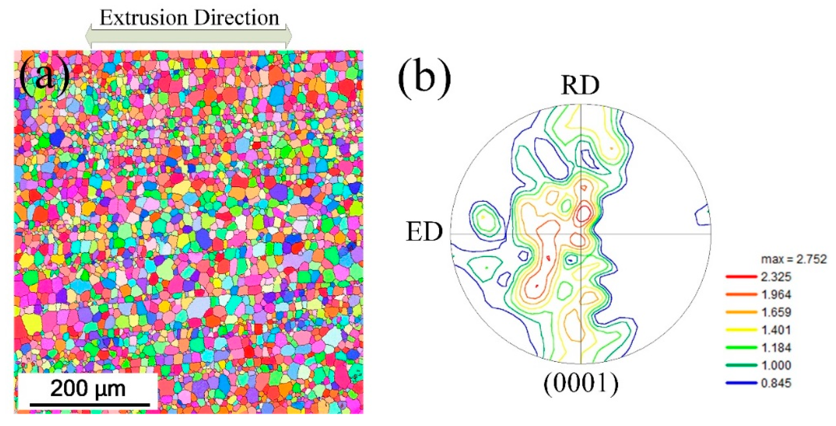
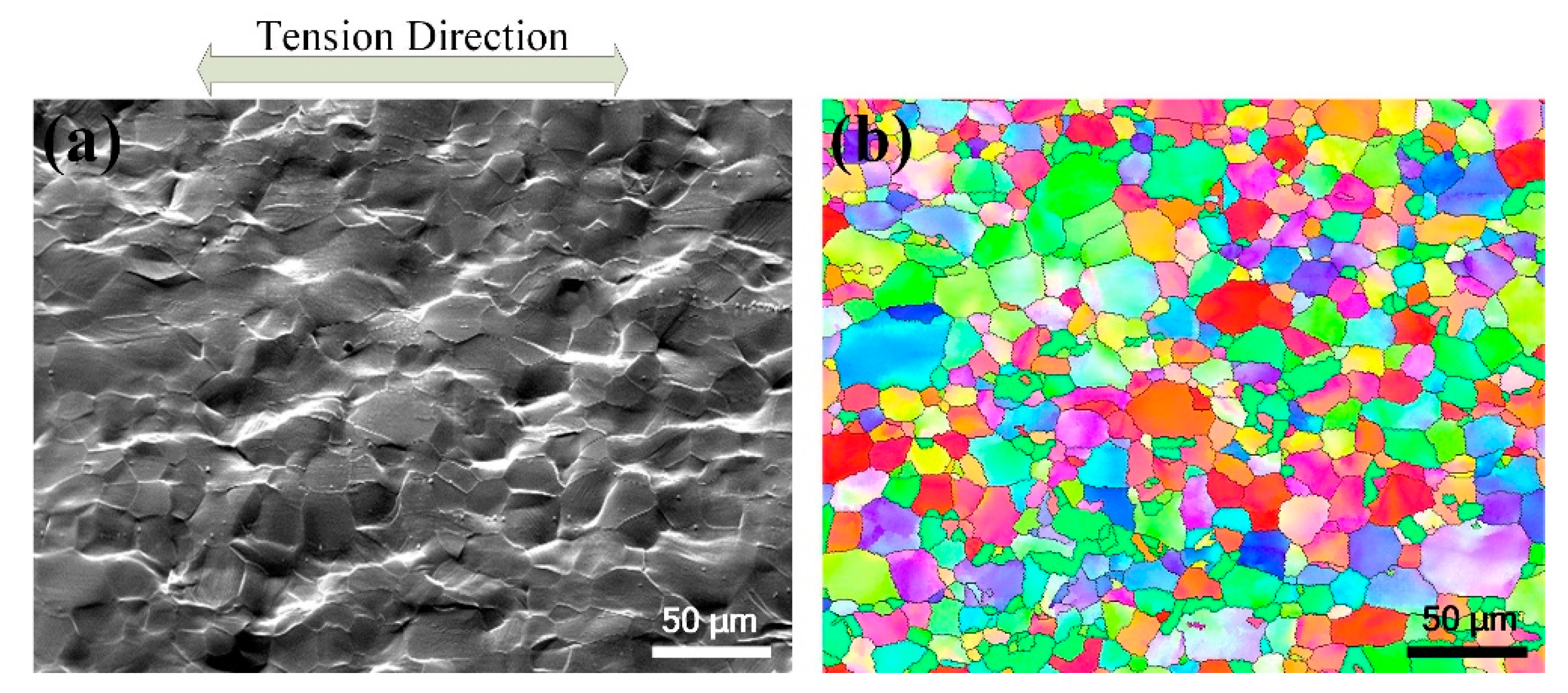
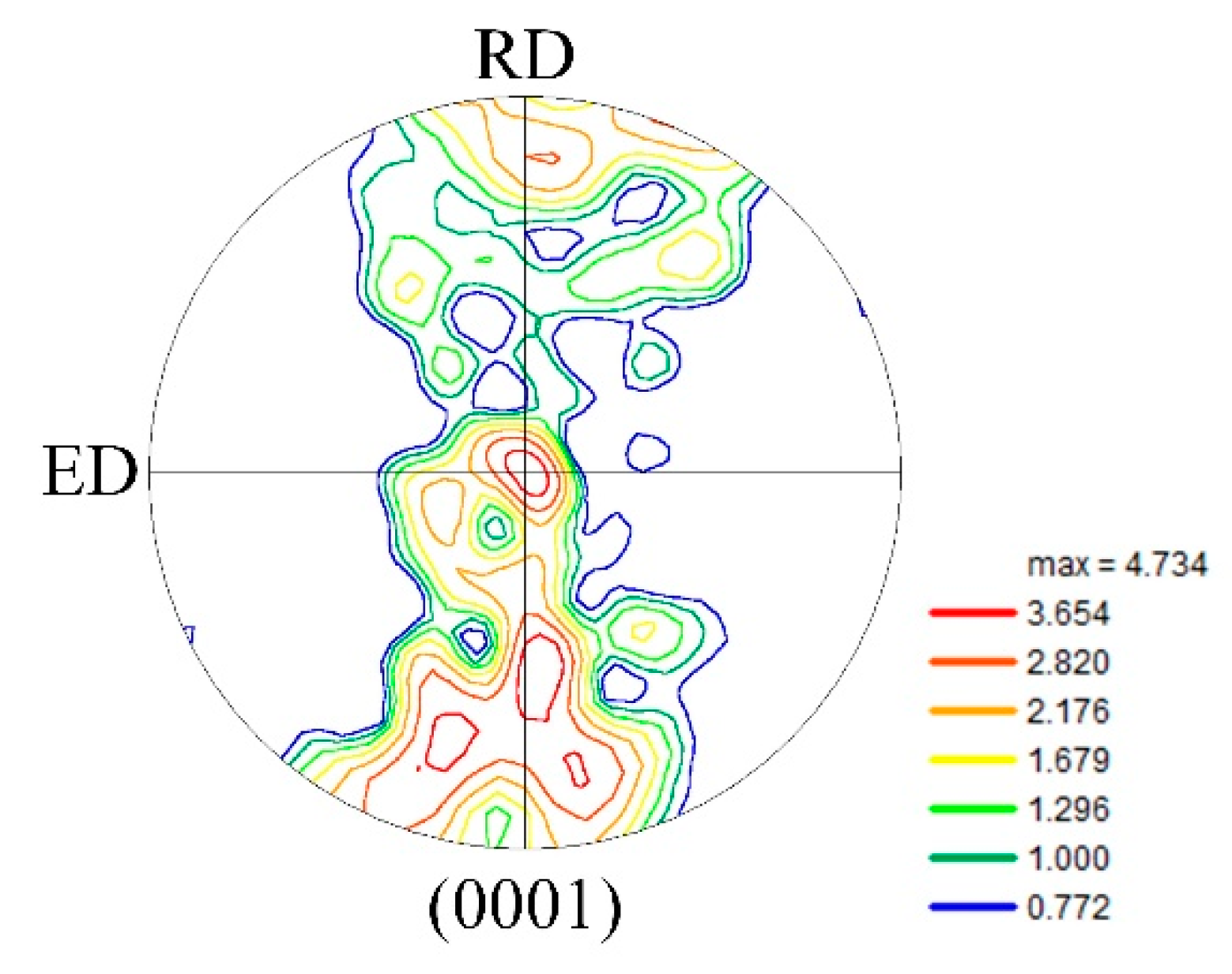
3.1. Initial Microstructure

Figure 1 shows the initial microstructure information. The material used in this paper is the same as in our previous study [12]. The figure is rotated 90° clock–wise, in order to show the frame of reference used in Figure 2, Figure 3, Figure 4, Figure 5 and Figure 6. A fully recrystallized microstructure with an average grain size of 25 μm can be found (Figure 1a). The initial texture of this Mg alloy, shown in Figure 1b, is relatively weak, and the highest texture intensity is only 2.752 which is lower than most of the current wrought Mg alloys.

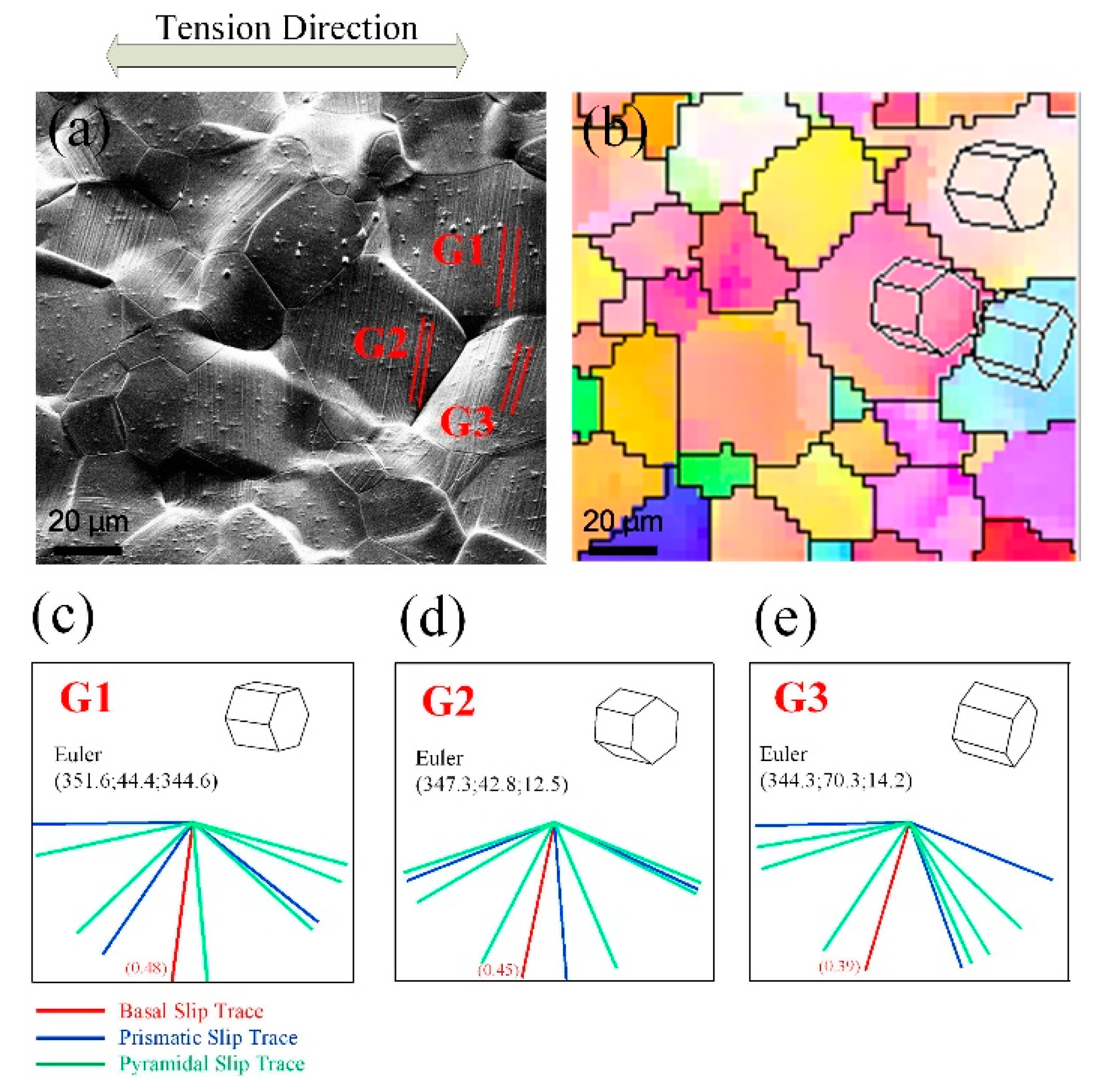
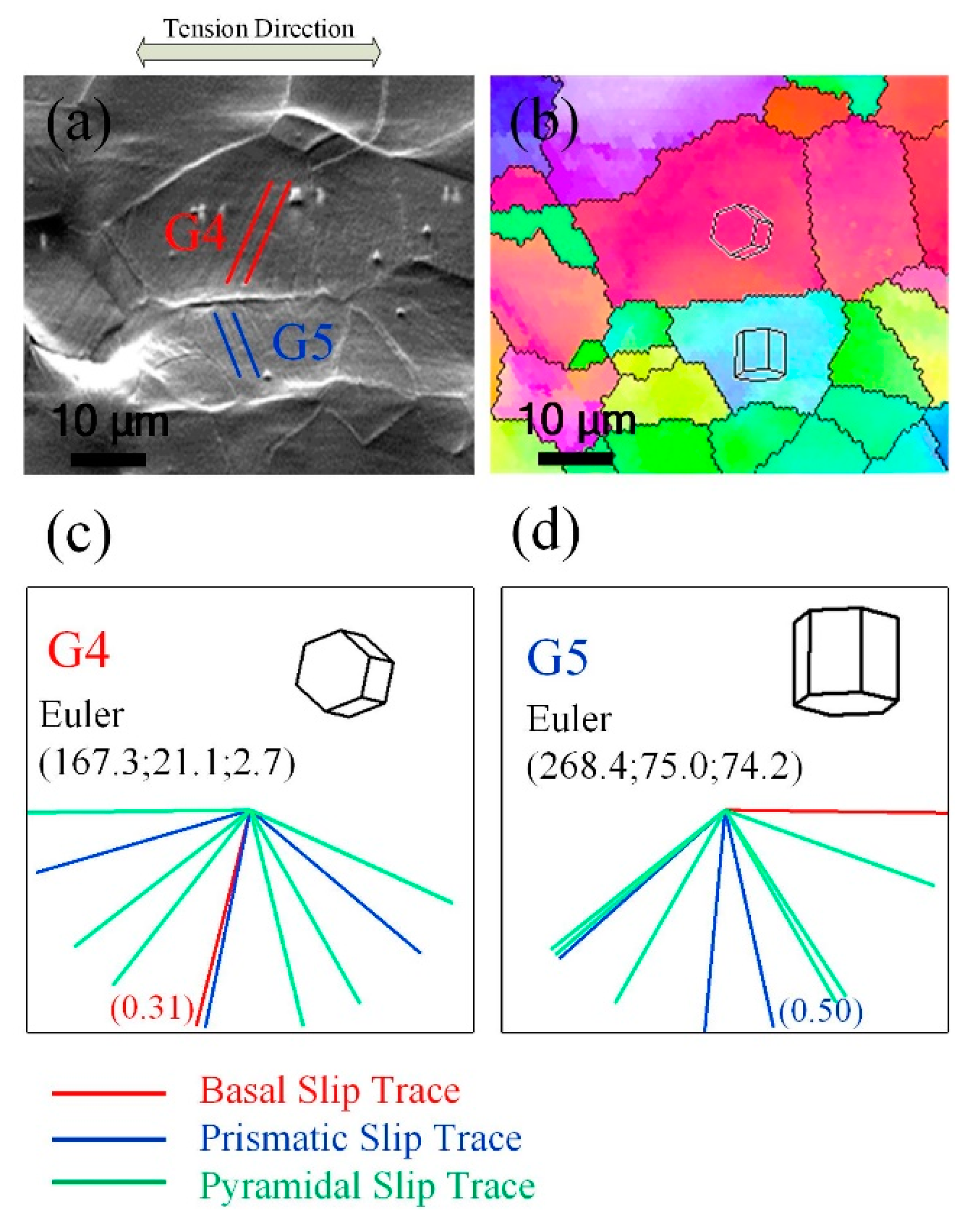
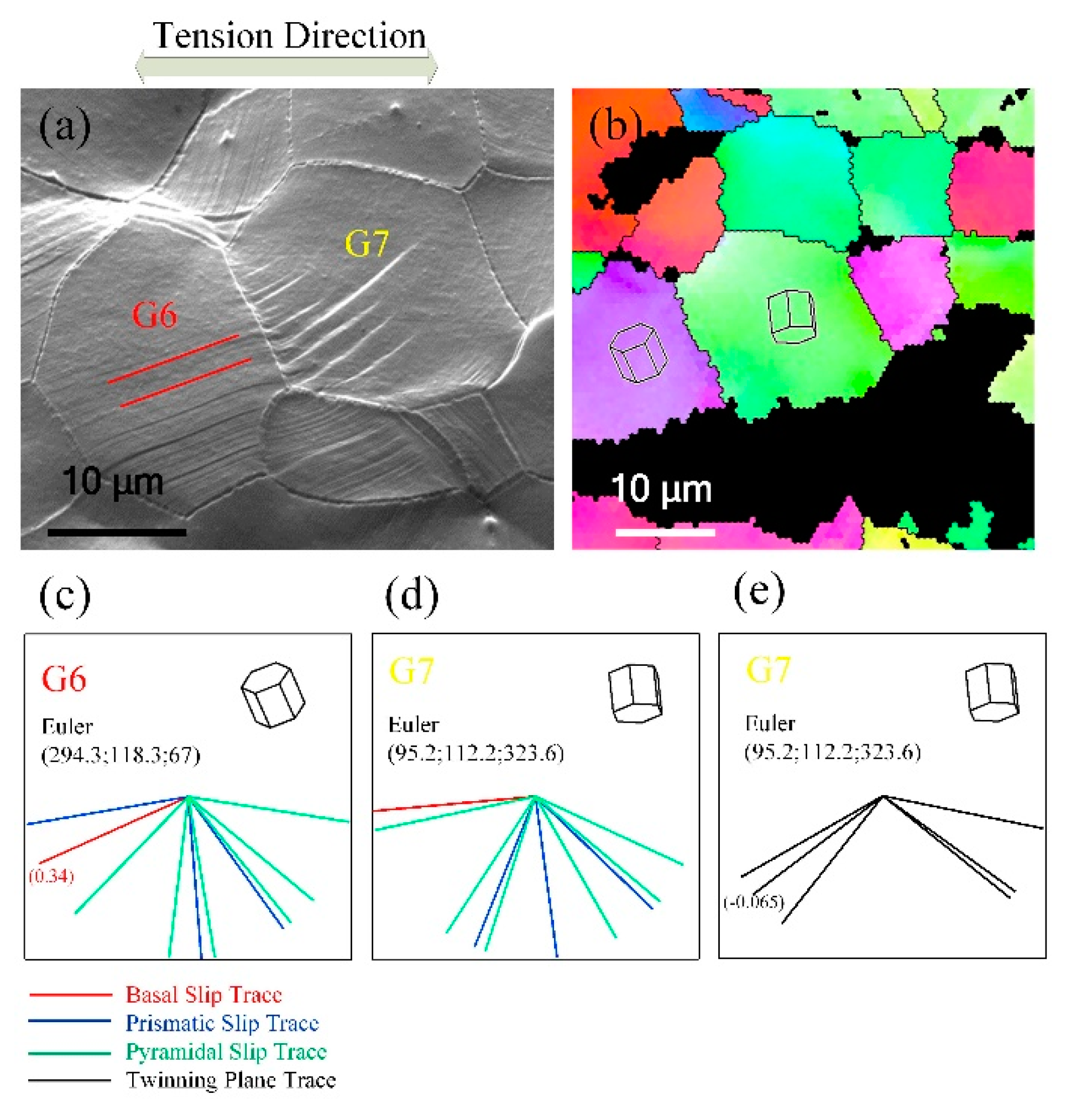
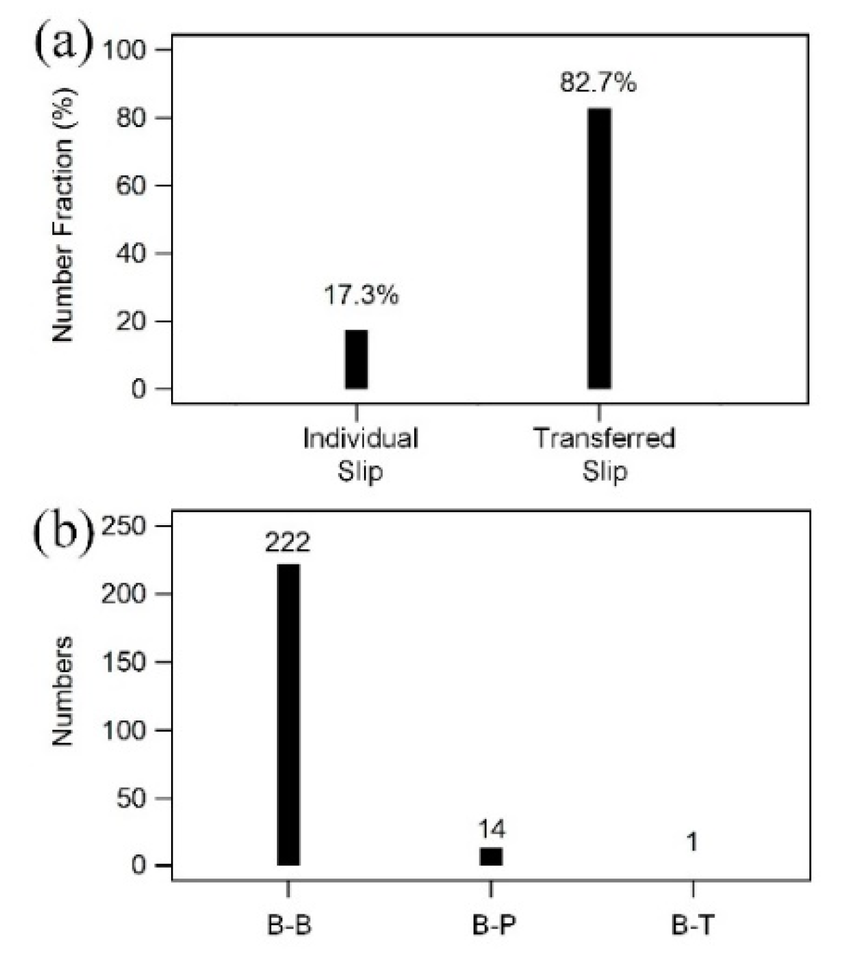
3.2. Slip Transfer at Grain–Boundary Area

Figure 2 shows the deformed microstructure after the tension test (ε = 0.1), and Figure 3 shows the pole figure (PF) after tension. Obvious slip traces in the grains and fluctuation at the grain boundaries can be seen. Using slip trace analysis, basal slip and first-order prismatic slip were found to be the dominant slip deformation modes and only a few {10 1 _ 2} <10 1 _ 1> instances of twinning can be found. In addition, many slip traces were found to be transferred through grain boundaries. SEM photographs of different kinds of slip traces with high magnification are shown in Figure 4, Figure 5 and Figure 6. Several kinds of slip and twinning in pairs can be found around grain boundaries. Basal slip traces were found to come in pairs with basal slip (named B–B, Figure 4), prismatic slip (named B–P, Figure 5), and {10 1 _ 2} <10 1 _ 1> twinning (named B–T, Figure 6). The statistical data in Figure 7a show that the number fraction of transferred slips across grain boundaries has a high proportion of above 80%. Additionally, the vast majority of these transferred slips were identified as basal slips (Figure 7b).
In Figure 4a, slip traces can be found in Grain 1, Grain 2 and Grain 3. Using slip trace analysis, as shown in Figure 4c–e, these slip traces were identified as basal slip traces with high Schmid factors of 0.48, 0.45 and 0.39, respectively.
A geometric compatibility factor m’, first defined by Luster and Morris [16], was employed.
m = c o s ψ × c o s κ
where ψ and κ are the angles between the active normal slip plane and slip directions, respectively.
Using this parameter, the geometric compatibility factor between the slip systems in adjacent grains may vary between 0 and 1. For m’ = 1, complete compatibility exists between the slip systems in the neighboring grains, and in this case, both the slip directions and the slip planes in each grain will be parallel. In contrast, m’ = 0 indicates that the slip systems are completely incompatible, such that either the slip directions or slip planes are orthogonal. In general, m’ will assume intermediate values between 0 and 1.
The geometric compatibility factors between the two slip systems in Grain 1 and Grain 2 are listed in Table 1. The highest value of geometric compatibility factor is 0.91 which indicates good compatibility for the activation of basal slip systems in the adjacent grains.
Schmid factor of basal slip in grains wherein the occurrence of transferred basal slip was calculated; the result is shown in Figure 8, with the comparison with the Schmid factor distribution in all grains (1231 grains were collected for the analysisi of Schmid factor). It can be seen that the relationship between the Schmid factor of the basal slip system and the activation of slip transfer at the grain–boundary area is weak. Therefore, it seems that the criterion for the activation of transferred basal slip cannot depend only on the value of the Schmid factor.

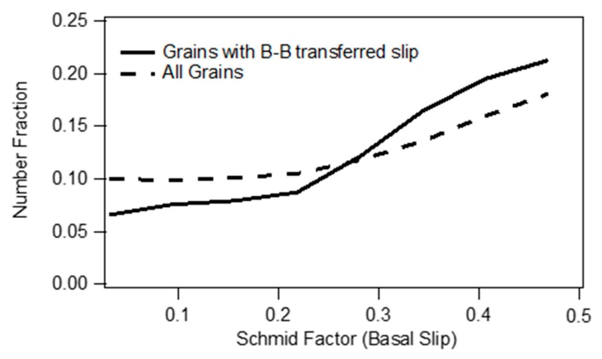
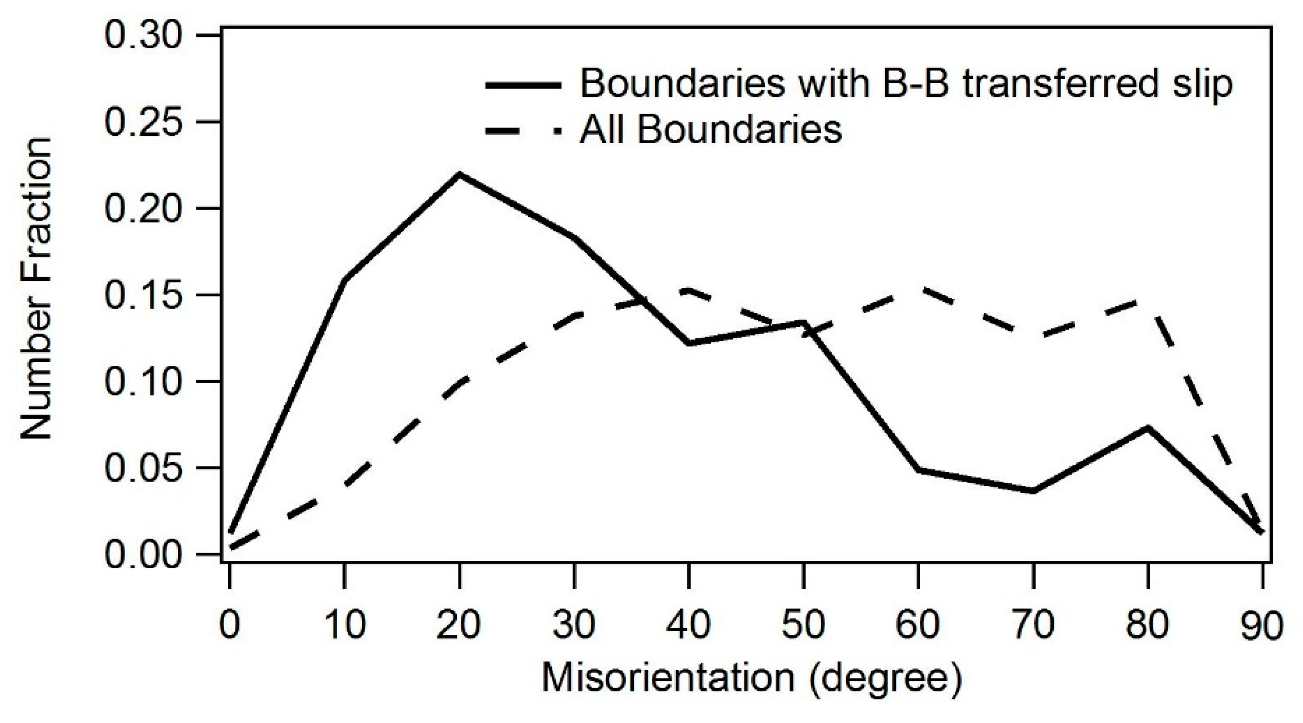
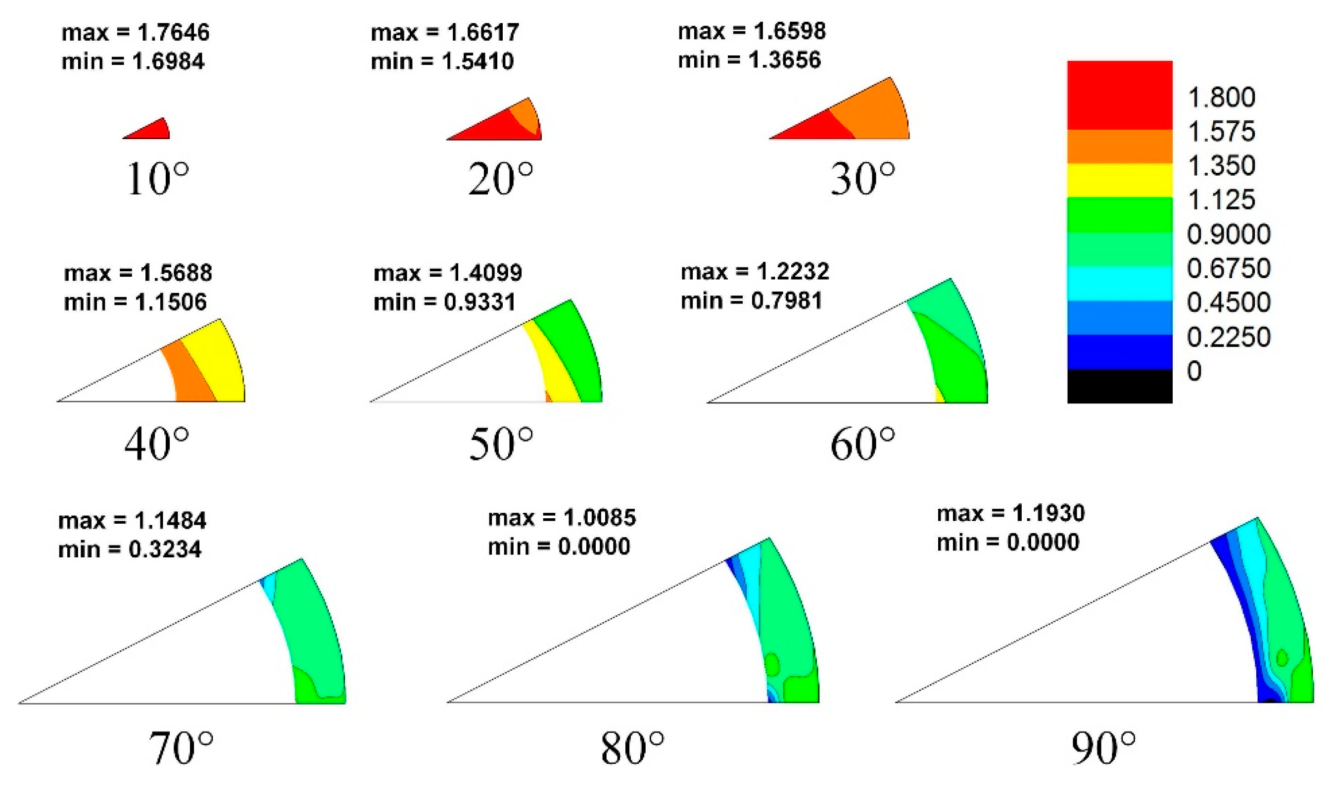
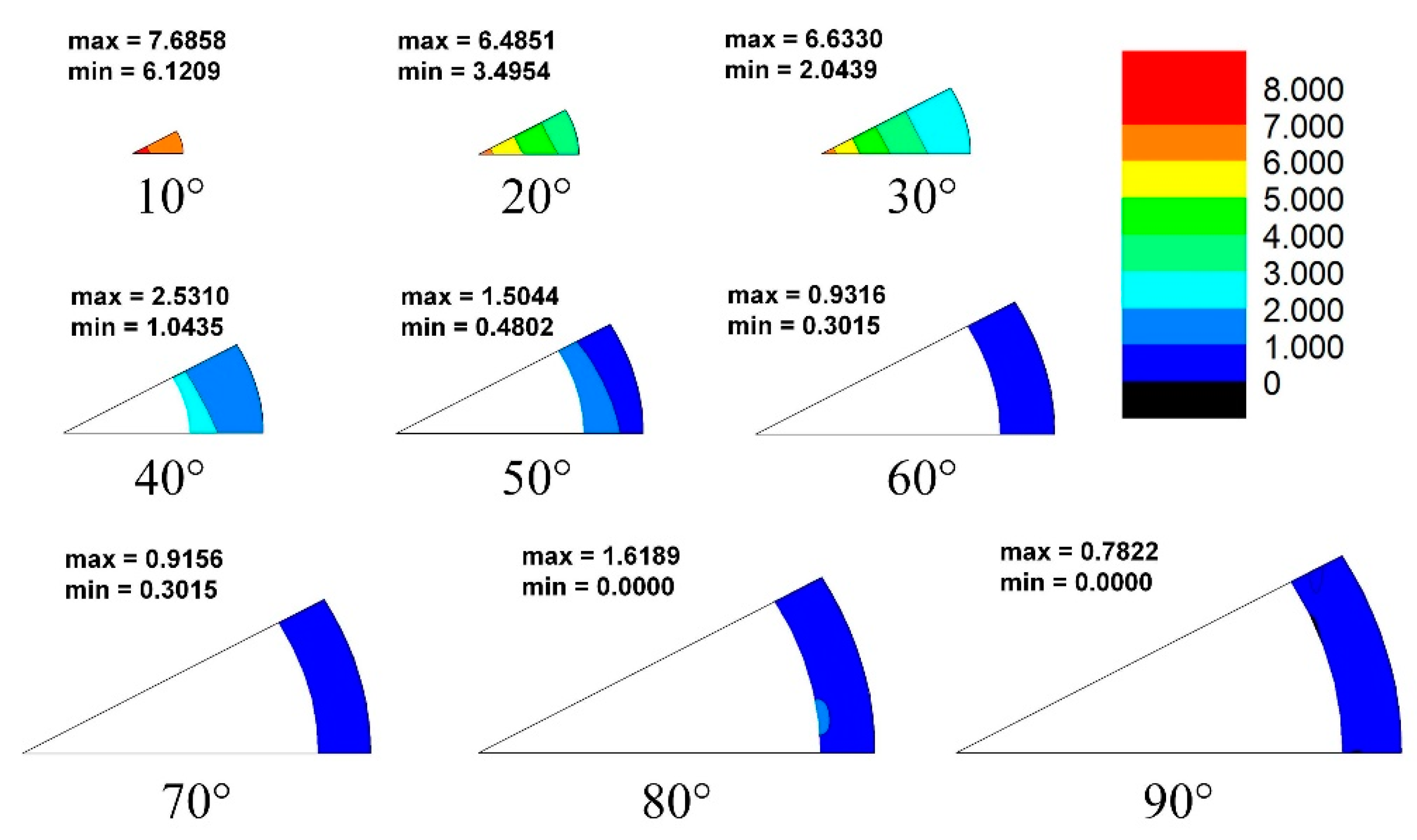
3.3. Effect of Grain–Boundary Misorientation Distribution on Slip Transfer

As the above results show, deformation behavior at grain level does not depend only on grain orientations, and the interaction between grains around grain-boundary areas appears to be significant during the deformation process. In this case, whether certain types of grain boundaries might favor transferred slips should be considered.
Figure 9 shows the misorientation angle distribution of boundaries with transferred basal slips across and all boundaries in this material (1632 grain boundaries were collected for the analysis of grain–boundary misorientation distribution). A significant difference can be found between these two distributions, and low–angle boundaries appear to favor transferred basal slips.
In order to fully understand the effect of grain boundary on the slip transfer phenomenon, MDF maps using the axis–angle parameters were draw to fully understand the geometric characteristics of these boundaries favored for transferred basal slip. Figure 10 shows the MDF of all boundaries in the Mg–Gd–Y alloy. The misorientation distribution is quite randomized, and the highest intensity is only 1.76. Figure 11 shows the MDF of the boundaries with transferred basal slips across them. Obvious high intensification can be found at low misorientation angles and especially around the axis around [0001]. By using the MDF method, it can easily be seen that the activation of the transferred basal slip system is preferred at boundaries with misorientation at the axis around [0001] and an angle of 0–30°.

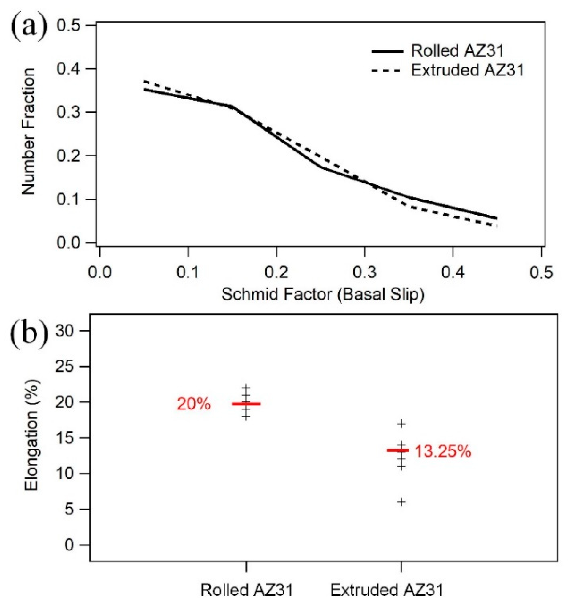
3.4. Effect of Grain–Boundary Misorientation Distribution on Ductility

The grain–boundary area preferred for more slip transfer would accommodate higher strain. If one polycrystalline magnesium alloy has more boundaries of the sort, the ductility of this material, theoretically, should be higher.
In order to support the arguments made in the present manuscript, data from two groups of Mg–3Al–1Zn (AZ31) alloy have been included. Figure 12 exhibits two groups of data, all from the Mg–3Al–1Zn (AZ31) alloy, which is the most common of the magnesium alloys. The manufacturing process for each is different; one involves rolling and the other involves extrusion. These two kinds of material show a similar Schmid factor distribution during tension along their prior working (rolling or extrusion) direction. However, the rolled AZ31 alloy shows much higher elongation than the extruded one (Figure 12b, data collected from the literature [17,18,19,20,21,22,23,24,25,26,27,28,29]). This phenomenon could not be explained based on the theory that a higher ductility is achieved by grain orientations favored for basal slip.
By analyzing the MDF of these two AZ31 alloys, in Figure 13 and Figure 14, a higher fraction of low-angle misorientation distribution was found in rolled AZ31 (600 boundaries were collected for the analysis of the misorientation distribution map for each of the AZ31 alloys). Therefore, with a higher fraction of boundaries favored for transferred slip, a higher elongation can be obtained in the rolled AZ31 alloy.
In past decades, texture-weakening has been proven to be a good method for improving the ductility of magnesium alloys [20,30]. With more grains favored for basal slips, the elongation of magnesium alloys during a tension test could be increased dramatically. The Mg–Gd–Y alloy shown in this paper has a weakened texture, and the maximum texture intensity is only 2.752. The results shown in this paper already prove that with a better deformation compatibility, the grain-boundary area can accommodate a higher strain and the magnesium materials can achieve higher ductility. Since it has been reported that misorientation distribution can be altered after heat treatment [31,32], the deformation compatibility of magnesium alloys could also be improved. Furthermore, high deformation compatibility, when combined with a randomized texture, would further improve the ductility of magnesium alloys.

4. Conclusions

(1)
The activation of slip crossed the grain boundary during tension deformation, and the basal slip system was the dominate type. Not a lot of twinning was observed on the surface after tension.
(2)
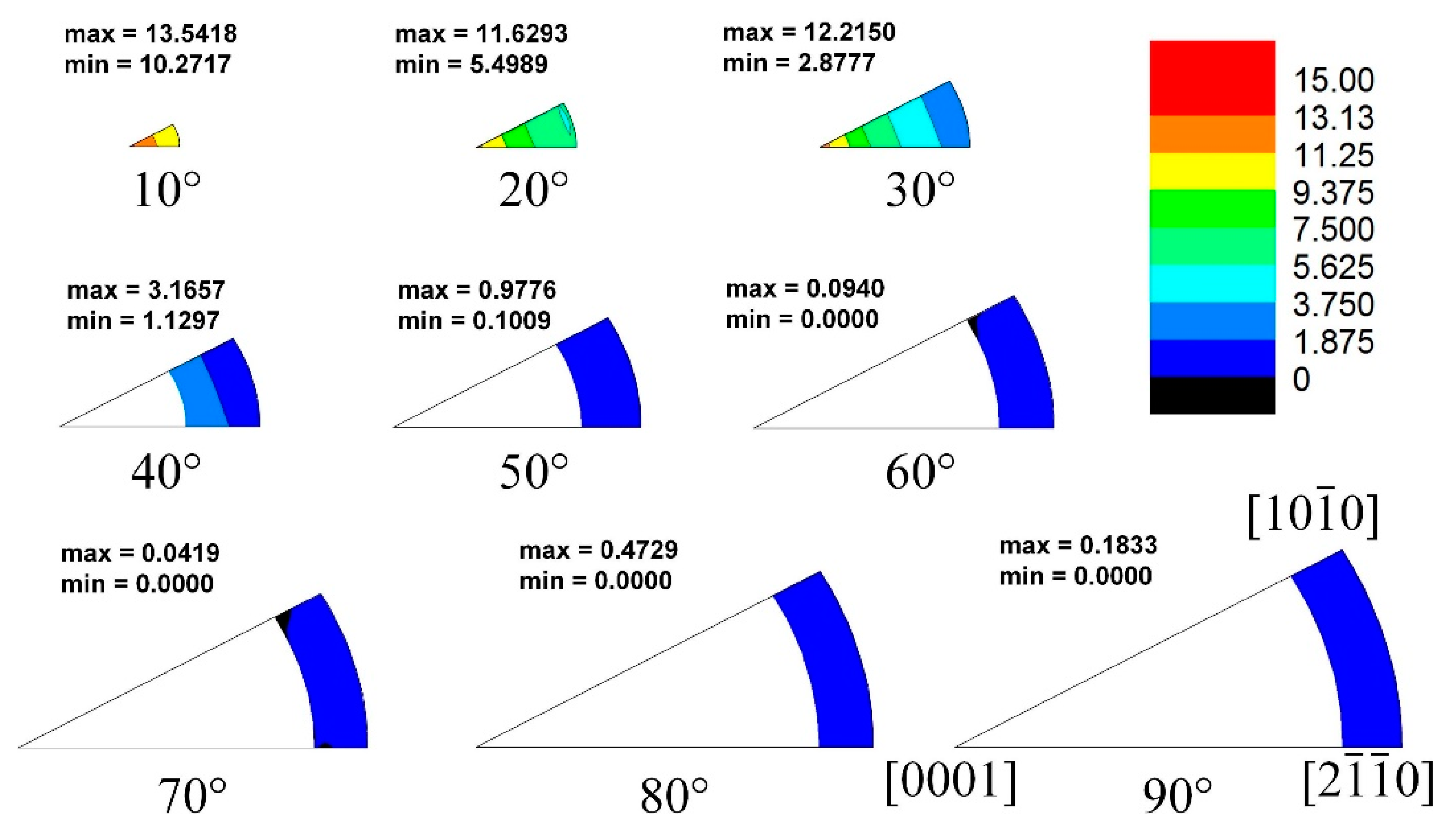
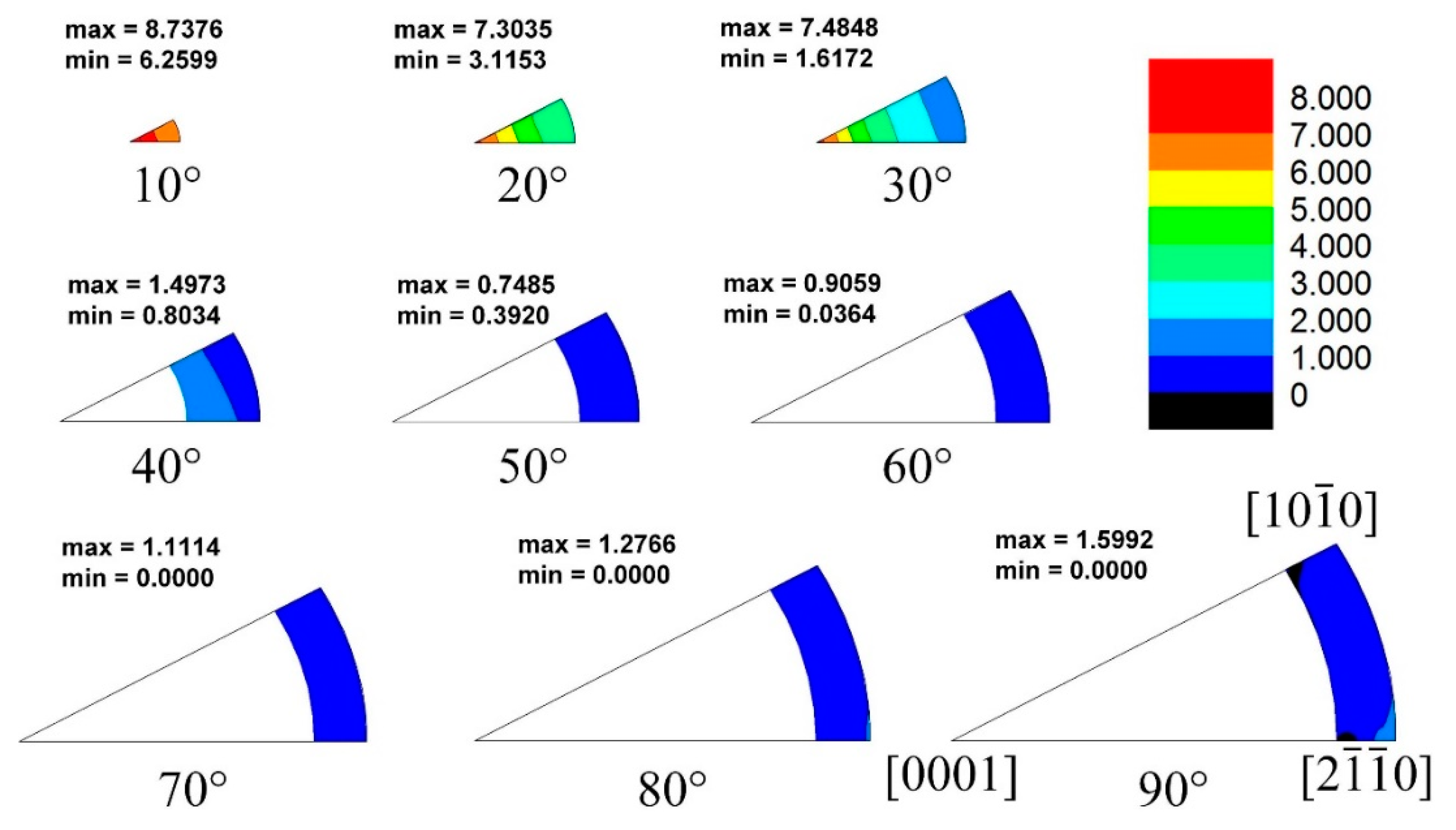
The activation of dislocation slip pairs was affected by the misorientation of grain boundaries. Grain boundaries with a misorientation around the [0001] axis and at a 10–30° angle promoted the activation of basal slip pairs.
(3)
The extruded AZ31 alloy showed higher elongation, because the extruded AZ31 alloy exhibited a higher fraction of grain-boundary misorientation around the [0001] axis at an angle of 0–30°.

Author Contributions

Formal analysis, J.S.; Methodology, J.S., J.L., Q.C. and L.L.; Project administration, J.S.; Writing—original draft, J.S.; Writing—review & editing, Y.Z. All authors have read and agreed to the published version of the manuscript.

Funding

This work was supported by the National Natural Science Foundation of China (Grant No. 52001188).

Data Availability Statement

Not applicable.

Conflicts of Interest

The authors declare no conflict of interest.

References

  1. Mordike, B.L.; Ebert, T. Magnesium: Properties—Applications—Potential, Mater. Sci. Eng. A 2001, 302, 37–45. [Google Scholar] [CrossRef]
  2. Luo, A.A. Magnesium: Current and potential automotive applications. JOM 2002, 54, 42–48. [Google Scholar] [CrossRef]
  3. Yoo, M.H. Slip, twinning, and fracture in hexagonal close-packed metals. Metall. Trans. A 1981, 12, 409–418. [Google Scholar] [CrossRef]
  4. Wang, F.; Sandlöbes, S.; Diehl, M.; Sharma, L.; Roters, F.; Raabe, D. In situ observation of collective grain-scale mechanics in Mg and Mg–rare earth alloys. Acta Mater. 2014, 80, 77–93. [Google Scholar] [CrossRef]
  5. Martin, G.; Sinclair, C.W.; Schmitt, J.-H. Plastic strain heterogeneities in an Mg–1Zn–0.5Nd alloy. Scr. Mater. 2013, 68, 695–698. [Google Scholar] [CrossRef]
  6. Martin, G.; Sinclair, C.W.; Lebensohn, R.A. Microscale plastic strain heterogeneity in slip dominated deformation of magnesium alloy containing rare earth. Mater. Sci. Eng. A 2014, 603, 37–51. [Google Scholar] [CrossRef]
  7. Stanford, N.; Sotoudeh, K.; Bate, P. Deformation mechanisms and plastic anisotropy in magnesium alloy AZ31. Acta Mater. 2011, 59, 4866–4874. [Google Scholar] [CrossRef]
  8. Panicker, R.; Chokshi, A.; Mishra, R.; Verma, R.; Krajewski, P. Microstructural evolution and grain boundary sliding in a superplastic magnesium AZ31 alloy. Acta Mater. 2009, 57, 3683–3693. [Google Scholar] [CrossRef]
  9. Jonas, J.J.; Mu, S.; Al-Samman, T.; Gottstein, G.; Jiang, L.; Martin, Ė. The role of strain accommodation during the variant selection of primary twins in magnesium. Acta Mater. 2011, 59, 2046–2056. [Google Scholar] [CrossRef]
  10. Barnett, M.R.; Keshavarz, Z.; Beer, A.G.; Ma, X. Non-Schmid behaviour during secondary twinning in a polycrystalline magnesium alloy. Acta Mater. 2008, 56, 5–15. [Google Scholar] [CrossRef]
  11. Jin, L.; Dong, J.; Sun, J.; Luo, A.A. In-situ investigation on the microstructure evolution and plasticity of two magnesium alloys during three-point bending. Int. J. Plast. 2015, 72, 218–232. [Google Scholar] [CrossRef]
  12. Sun, J.; Jin, L.; Dong, J.; Ding, W.; Luo, A.A. Microscopic deformation compatibility during monotonic loading in a Mg-Gd-Y alloy. Mater. Charact. 2016, 119, 195–199. [Google Scholar] [CrossRef]
  13. Sun, J.; Jin, L.; Dong, J.; Wang, F.; Dong, S.; Ding, W.; Luo, A.A. Towards high ductility in magnesium alloys—The role of intergranular deformation. Int. J. Plast. 2019, 123, 121–132. [Google Scholar] [CrossRef]
  14. Patala, S.; Mason, J.K.; Schuh, C.A. Improved representations of misorientation information for grain boundary science and engineering. Prog. Mater. Sci. 2012, 57, 1383–1425. [Google Scholar] [CrossRef]
  15. Mason, J.; Schuh, C. Hyperspherical harmonics for the representation of crystallographic texture. Acta Mater. 2008, 56, 6141–6155. [Google Scholar] [CrossRef]
  16. Luster, J.; Morris, M.A. Compatibility of deformation in two-phase Ti-Al alloys: Dependence on microstructure and orientation relationships. Metall. Mater. Trans. A 1995, 26, 1745–1756. [Google Scholar] [CrossRef]
  17. Keshavarz, Z.; Barnett, M.R. EBSD analysis of deformation modes in Mg–3Al–1Zn. Scr. Mater. 2006, 55, 915–918. [Google Scholar] [CrossRef]
  18. Yi, S.-B.; Davies, C.; Brokmeier, H.-G.; Bolmaro, R.; Kainer, K.; Homeyer, J. Deformation and texture evolution in AZ31 magnesium alloy during uniaxial loading. Acta Mater. 2006, 54, 549–562. [Google Scholar] [CrossRef]
  19. Wang, F.; Feng, M.; Jiang, Y.; Dong, J.; Zhang, Z. Cyclic deformation and fatigue of extruded Mg–Gd–Y magnesium alloy. J. Mater. Sci. Technol. 2013, 561, 403–410. [Google Scholar] [CrossRef]
  20. Hirsch, J.; Al-Samman, T. Superior light metals by texture engineering: Optimized aluminum and magnesium alloys for automotive applications. Acta Mater. 2013, 61, 818–843. [Google Scholar] [CrossRef]
  21. Xiong, Y.; Yu, Q.; Jiang, Y. Multiaxial fatigue of extruded AZ31B magnesium alloy. Mater. Sci. Eng. A 2012, 546, 119–128. [Google Scholar] [CrossRef]
  22. Yi, S.; Bohlen, J.; Heinemann, F.; Letzig, D. Mechanical anisotropy and deep drawing behaviour of AZ31 and ZE10 magnesium alloy sheets. Acta Mater. 2010, 58, 592–605. [Google Scholar] [CrossRef] [Green Version]
  23. Wu, L.; Agnew, S.; Ren, Y.; Brown, D.; Clausen, B.; Stoica, G.; Wenk, H.; Liaw, P. The effects of texture and extension twinning on the low-cycle fatigue behavior of a rolled magnesium alloy, AZ31B. Mater. Sci. Eng. A 2010, 527, 7057–7067. [Google Scholar] [CrossRef]
  24. Begum, S.; Chen, D.; Xu, S.; Luo, A.A. Low cycle fatigue properties of an extruded AZ31 magnesium alloy. Int. J. Fatigue 2009, 31, 726–735. [Google Scholar] [CrossRef]
  25. Stanford, N.; Barnett, M. Effect of composition on the texture and deformation behaviour of wrought Mg alloys. Scr. Mater. 2008, 58, 179–182. [Google Scholar] [CrossRef]
  26. Chino, Y.; Kimura, K.; Mabuchi, M. Twinning behavior and deformation mechanisms of extruded AZ31 Mg alloy. Mater. Sci. Eng. A 2008, 486, 481–488. [Google Scholar] [CrossRef]
  27. Chino, Y.; Kimura, K.; Hakamada, M.; Mabuchi, M. Mechanical anisotropy due to twinning in an extruded AZ31 Mg alloy. Mater. Sci. Eng. A 2008, 485, 311–317. [Google Scholar] [CrossRef]
  28. Agnew, S.R.; Duygulu, Ö. Plastic anisotropy and the role of non-basal slip in magnesium alloy AZ31B. Int. J. Plast. 2005, 21, 1161–1193. [Google Scholar] [CrossRef]
  29. Barnett, M.; Keshavarz, Z.; Beer, A.; Atwell, D. Influence of grain size on the compressive deformation of wrought Mg–3Al–1Zn. Acta Mater. 2004, 52, 5093–5103. [Google Scholar] [CrossRef]
  30. Luo, A.; Mishra, R.; Sachdev, A. High-ductility magnesium–zinc–cerium extrusion alloys. Scr. Mater. 2011, 64, 410–413. [Google Scholar] [CrossRef]
  31. Yi, S.; Brokmeier, H.-G.; Letzig, D. Microstructural evolution during the annealing of an extruded AZ31 magnesium alloy. J. Alloy. Compd. 2010, 506, 364–371. [Google Scholar] [CrossRef] [Green Version]
  32. Wu, W.; Jin, L.; Zhang, Z.; Ding, W.; Dong, J. Grain growth and texture evolution during annealing in an indirect-extruded Mg–1Gd alloy. J. Alloy. Compd. 2014, 585, 111–119. [Google Scholar] [CrossRef]
Figure 1. Initial Mg–8.0Gd–3.0Y–0.5 Zr alloy microstructure: (a) IPF map; (b) PF map.
Crystals 12 00388 g001
Figure 2. SEM map (a) and the corresponding IPF (b) after 10% tensile strain in Mg–8.0Gd–3.0Y–0.5 Zr alloy.
Crystals 12 00388 g002
Figure 3. PF map after 10% tensile strain in Mg–8.0Gd–3.0Y–0.5 Zr alloy.
Crystals 12 00388 g003
Figure 4. (a) SEM micrograph of Mg–8.0Gd–3.0Y–0.5 Zr alloy after tension test at strain of 0.1; (b) the corresponding IPF map; (c) possible slip trace directions in Grain 1; (d) possible slip trace directions in Grain 2; (e) possible slip trace directions in Grain 3.
Crystals 12 00388 g004
Figure 5. (a) SEM micrograph of Mg–8.0Gd–3.0Y–0.5 Zr alloy after tension test at strain of 0.1; (b) the corresponding IPF map; (c) possible slip trace directions in Grain 4; (d) possible slip trace directions in Grain 5.
Crystals 12 00388 g005
Figure 6. (a) SEM micrograph of Mg–8.0Gd–3.0Y–0.5 Zr alloy after tension test at strain of 0.1; (b) the corresponding IPF map; (c) possible slip trace directions in Grain 6; (d) possible slip trace directions in Grain 7; (e) possible twinning boundary trace directions in Grain 7.
Crystals 12 00388 g006
Figure 7. (a) The number fractions of grains with slip traces observed, and (b) the number of grains with different transferred slip modes observed (94% are B–B).
Crystals 12 00388 g007
Figure 8. Relationship between Schmid factor of basal slip and number fraction of B–B transferred slip.
Crystals 12 00388 g008
Figure 9. Relationship between misorientation angle and number fraction of B–B transferred slip.
Crystals 12 00388 g009
Figure 10. Misorientation distribution map of Mg–8.0Gd–3.0Y–0.5 Zr alloy.
Crystals 12 00388 g010
Figure 11. Misorientation distribution map of B–B slip transferred boundaries.
Crystals 12 00388 g011
Figure 12. (a) Schmid factor distribution, and (b) elongation during tension tests of typical rolled AZ31 alloys and extruded alloys (data collected from the literature).
Crystals 12 00388 g012
Figure 13. Misorientation distribution map of rolled AZ31 alloy.
Crystals 12 00388 g013
Figure 14. Misorientation distribution map of extruded AZ31 alloy.
Crystals 12 00388 g014
Table 1. m’ value between basal slip systems in Grain 1 and Grain 2.
G1Basal [11-20]
(0.27)
Basal [1-210]
(0.48)
Basal [-2110]
(0.23)
G2
Basal [11-20]
(0.41)
0.910.090.82
Basal [1-210]
(0.45)
0.820.910.09
Basal [-2110]
(0.04)
0.090.810.91
Publisher’s Note: MDPI stays neutral with regard to jurisdictional claims in published maps and institutional affiliations.

