Article

Microstructure and Hot Deformation Behaviour of Twin-Roll Cast AZ31 Magnesium Wire

Institute of Metal Forming, Technische Universität Bergakademie Freiberg, Bernhard-von-Cotta-Straße 4, 09599 Freiberg, Germany
*
Author to whom correspondence should be addressed.
Crystals 2022, 12(2), 173; https://doi.org/10.3390/cryst12020173
Submission received: 30 November 2021 / Revised: 20 January 2022 / Accepted: 21 January 2022 / Published: 25 January 2022
(This article belongs to the Special Issue Hot Deformation Characteristics of Metallic Materials)

Abstract

:
Due to their low density and high specific strength, magnesium alloys offer great potential as a design material for lightweight construction. An economical and energy-efficient method for the production of magnesium wire is the technology of twin-roll casting. In this work, the deformation behaviour of twin-roll cast and heat-treated AZ31 wire pre-profile is investigated for the first time during the compression test at different temperatures (250–400 °C) and forming speeds (0.01–10 s−1). To obtain optimal parameters, a processing map is created, and the microstructural changes during the hot forming processes are determined by accompanying microstructure characterization through an optical microscope and scanning electron microscope. The heat treatment causes a reduction in segregation and a homogeneous microstructure. The average activating energy for plastic deformation of twin-roll cast and heat-treated magnesium alloy AZ31 is 159.008 kJ · mol 1 . The instability region of the process map starts at a forming temperature of 250 °C and extends into the range of high forming speeds (1–10 s−1). In this area, cracks in the microstructure can be detected during hot forming. At high temperatures (300–350 °C), dynamic recrystallization at the grain boundaries is observed as the main forming mechanism. Based on these results and observations, existing models for describing the hot forming behaviour of magnesium alloys can be extended and validated.

1. Introduction

A central approach for solving the global environmental and climate problem is lightweight design. Due to its lower density and high specific strength, the use of magnesium alloys as a design material is particularly interesting in the automotive industry for reducing fuel consumption and thus lowering CO2 emissions [1]. Independent of its use as a lightweight material in the automotive industry, there are various other fields of application, such as aerospace, the electrical industry as well as medical, sports and defence technology [2,3]. For the manufacture of modern lightweight structures from magnesium alloys, suitable welding and joining techniques are necessary. This requires the production of magnesium pre-products for the fabrication of welding rods and screws. Conventionally, magnesium alloy wires are manufactured by casting and subsequent extrusion. In addition to the many process steps with correspondingly needed intermediate heating, the limitation of the wire length is also a disadvantage. An economical and energy-efficient method for the production of magnesium flat products is twin-roll casting, which has already been successfully tested for strip material at the Institute for Metal Forming (IMF) at the TU Bergakademie Freiberg (TUBAF) [3,4]. A successful transfer of the technology to wire production took place (patent no. DE102012209568) [5]. The pilot plant to produce twin-roll cast magnesium wire pre-profiles was put into service at the end of 2017. Through the combination of the two process steps of solidification and forming, it is possible to produce a semi-finished product close to the final geometry economically. Compared to casted material, a unique microstructure and improved properties are achieved, such as a reduction of segregations, enhanced homogeneity and a finer distribution of precipitates [6,7]. This work focuses on microstructural investigations and the hot forming behaviour of the alloy AZ31. For the first time, a processing map based on the theory of the dynamic material model (DMM) [8] was used to illustrate the hot forming behaviour of the twin-roll cast wire in the heat-treated state (460 °C, 15 min). With the help of the processing map, the formability of the material at different forming temperatures and speeds can be represented. Combined with the consideration of the dynamic recrystallisation mechanisms, this enables the determination of the optimal process parameters and provides information about the hot formability of the material.

2. Materials and Methods

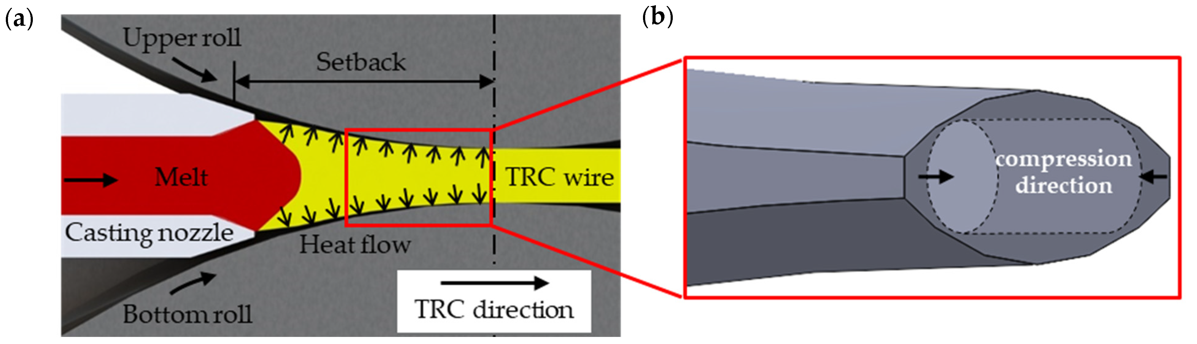
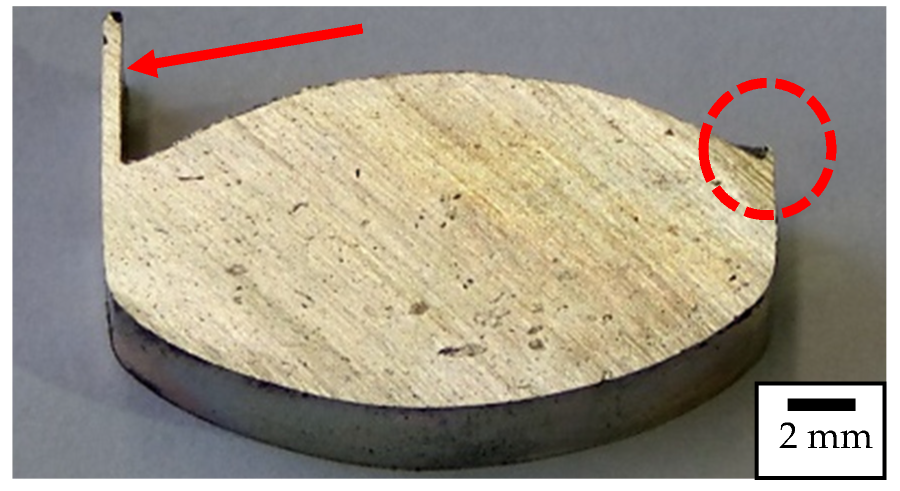
2.1. Twin-Roll Casting

The twin-roll casting plant of the IMF of TUBAF produces the wire pre-profile. For the process, ingots of the magnesium alloy AZ31 (chemical composition is shown below in Table 1) are first melted and then transferred through a heated pipe into the headbox to a corresponding casting level. The 710 °C hot melt is poured through a preheated nozzle into the water-cooled closed groove (see Figure 1a below). At this point, the melt solidifies quickly without any release agent at a twin-roll casting speed of 4.9 m/min. The oval cross-section of the groove is 20.0 mm × 9.2 mm.

2.2. Heat Treatment and Cylinder Compression Test

The heat treatment is carried out at 460 °C for 15 min according to Moses et al. (2019) [10], in which the twin-roll cast wire pre-profile is placed in a preheated industrial furnace and rapidly cooled in water (room temperature) after the holding time. Cylindrical specimens of 5 mm diameter and 10 mm height (Figure 1b) were mechanically manufactured from the heat-treated wire pre-profile. These cylindrical compression test specimens were tested several times with the quenching and forming dilatometer BÄHR DIL 805 D (company BÄHR-Thermoanalyse) at temperatures of 250, 300, 350 and 400 °C and speeds of 0.01, 0.1, 1 and 10 s−1 up to a logarithmic forming degree φ of 0.4. At first, with a heating rate of 5 °K/s, the samples are heated to forming temperature. After a holding time of 30 s, the specimens are deformed and then quenched (cooling rate approx. 100 K/s). Finally, the recorded flow curves are evaluated and corrected for temperature and friction.

2.3. Microstructural Methods

The optical characterization of the different states and the associated microstructures are performed with the VHX-6000 digital microscope (Keyence Corporation, Osaka, Japan). Therefore, the samples are hot embedded in a longitudinal section and ground with silicon carbide abrasive paper in four different steps. After an ultrasonic bath, the polishing of the ground samples is carried out with MD-Chem OPS 300 magnesium polishing cloths and OP-chem. Finally, the samples are etched with picric acid for 15 to 30 s. In addition, the mean chord length is determined with a class width of 5 μm using the linear intercept method. According to this method, the mean chord length is taken as the mean grain diameter.
Furthermore, the ZEISS GeminiSEM 450 scanning electron microscope is used to measure the alloy composition utilizing energy-dispersive X-ray spectroscopy (EDS). Texture analyses were performed by electron backscatter diffraction (EBSD) using the Oxford AZtecHKL data collection software (version 5.0, Oxford Instruments, Abingdon, UK). An accelerating voltage of 12 kV and a step size from 0.1 to 1 µm were used. The MTEX MATLAB toolbox was used to analyze the EBSD data [11].

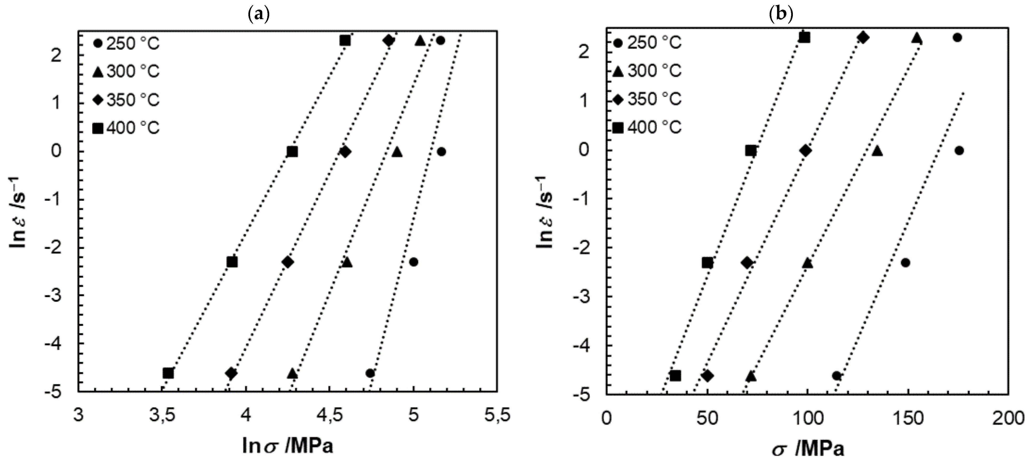
2.4. Theory of Processing Maps

For validation and optimisation of the process parameters, the DMM theory described by Prasad et al. (2015) [8] is applied, which allows the presentation of the hot forming behaviour of difficult-to-form materials. The processing maps based on this approach are described by temperature- and velocity-dependent stability criteria. This microstructure development and material behaviour can be explained using the continuum approach. Therefore, the system is regarded as a mechanical process. Here, the applied power P is dissipated into the hot-formed samples. This power consists of the dissipation component G and the co-dissipation component J. The G term describes the power that dissipates into heat during the hot forming process. In addition, the co-dissipation content J depends on the dynamically occurring metallurgical mechanisms during the power dissipation. Equation (1) below shows the relationship. Furthermore, for each temperature T and forming speed can be determined as the strain rate sensitivity m (see Equation (2)).
P = G + J = 0 ε · σ · d ε · + 0 σ ε · · d σ = σ · ε ·
J G = σ · d ε · ε · · d σ = ln σ ln ε · T ,   φ = m
To fit the experimental data, a polynomial equation for the ln σ data can be expressed as follows (Equation (3)):
ln σ = a + b · ln ε · + c   ln ε · 2 + d · ln ε · 3
Polynomial regression can be used to determine the constants (a, b, c and d) at different temperatures. The strain rate sensitivity can be described by the following Equation (4):
m = b + 2 · c · ln ε · + 3 · d · ln ε · 2
The combination of the energy dissipation efficiency η and the instability parameter ξ ε · at a constant logarithmic forming rate results in the process map. The energy dissipation efficiency and the instability parameter can be expressed by the following Equations (5) and (6):
η = 2 · m m + 1
ξ ε · = ln m m + 1 ln ε · + m 0
A negative value of the instability parameter indicates that the entropy flux due to microstructural change is smaller than the entropy flux externally induced by the thermo-mechanical processes. The DMM allows the development of a two-dimensional processing map for the hot forming behaviour within certain temperature and forming rate fields, in which the dissipation efficiency is combined with the ranges of the instability parameter.

3. Results

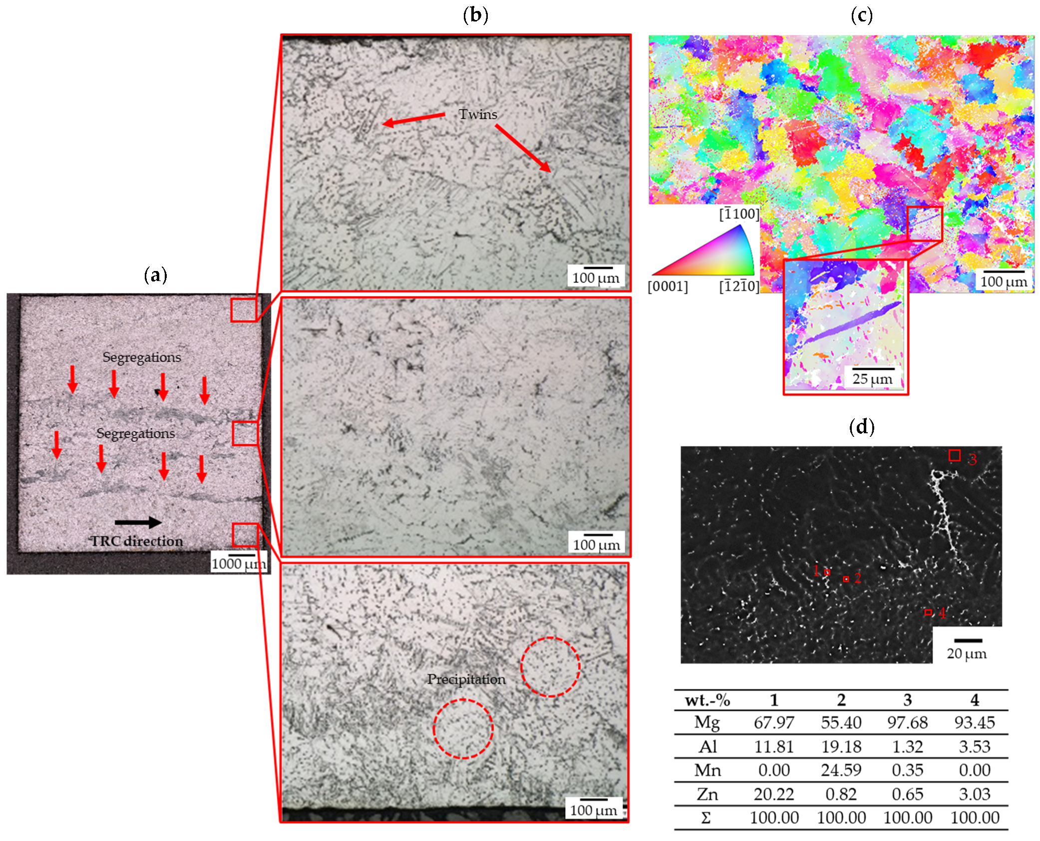
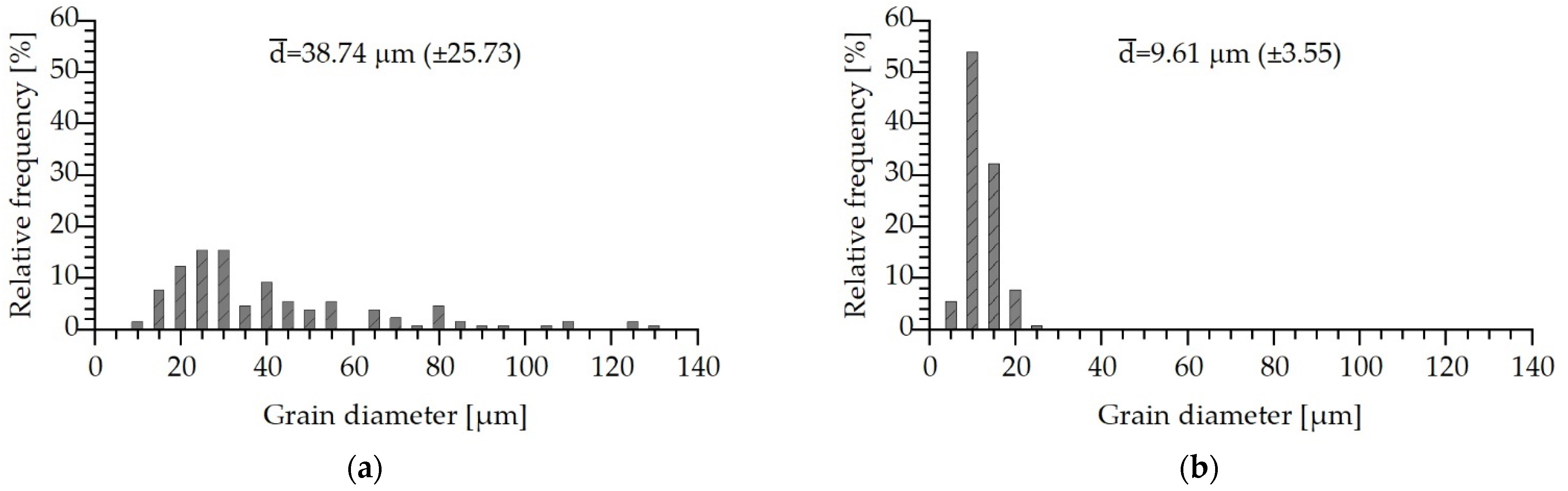
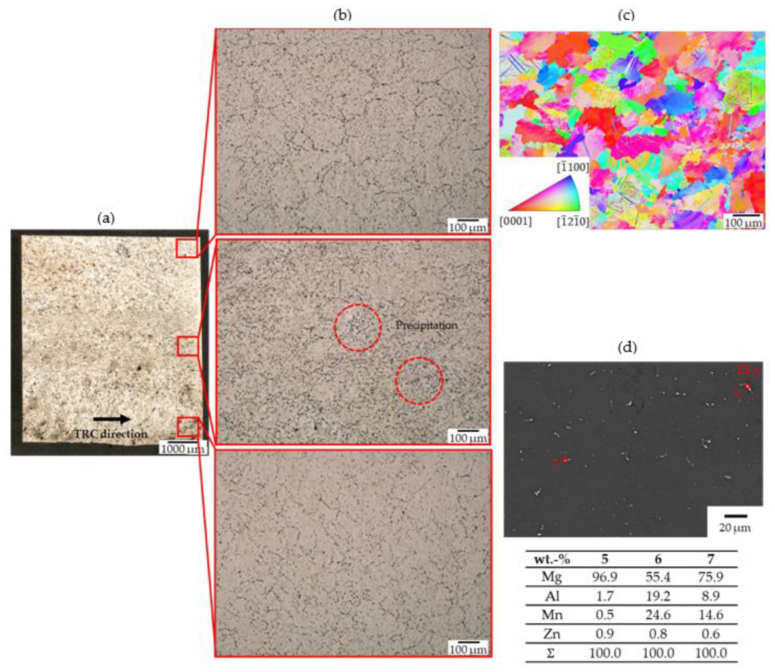
3.1. Microstructure of Twin-Roll Cast Alloy

Burrs have formed on the upper edges of the oval magnesium wire profile because melt flows into the narrow gap between the top and bottom rolls due to the process and solidifies there (see Figure 2 below). This formation can occur on one side as well as on both sides.
In the twin-roll cast initial state (see Figure 3a), clearly pronounced segregation zones can be seen in the centre and in the lower third of the longitudinal view. The detailed images (see Figure 3b) show spherical precipitations, and twins and segregations at the grain boundaries are noticeable. In addition, Figure 3c shows an EBSD measurement of the edge area where the grain boundaries and twins can be seen. Elongated precipitation appears at the grain boundaries at point 1 (Figure 3d). Aluminum and zinc enrichments are detected through the EDS measurement. The spherical shaped precipitation in point 2 is indicated as Al8Mn5 precipitation due to the atomic ratio (Al/Mn = 1.6) [12].
Figure 4 shows the histograms of the grain size distribution. In the edge area (see Figure 4a) of the twin-roll cast wire pre-profile, a broad distribution of grain diameter appears that indicates an inhomogeneous microstructure. The mean grain diameter d ¯ reaches a value of 38.74 μ m . In the centre of the magnesium wire, mostly smaller grains occur (see Figure 4b). Here, a fine-grained structure can be assumed, which is supported by the average grain diameter of 9.61 μm. Thus, it can be summarised that the twin-roll cast magnesium wire profile has a fine-grained microstructure in the centre and tends to form coarse grains in the peripheral zones.

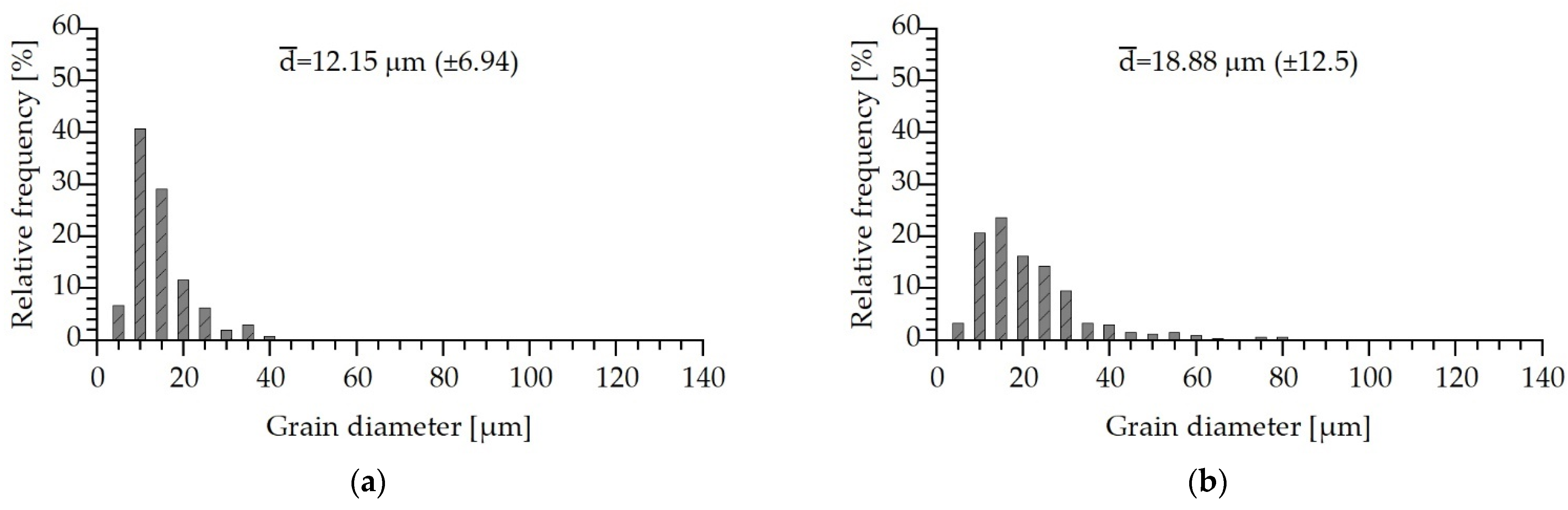
3.2. Microstructure of the Annealed Alloy

For a homogeneous microstructure with equiaxed grains, the twin-roll cast magnesium wire pre-profile is annealed at 460 °C for 15 min and afterward quenched in water [10]. During this heat treatment, the segregations that occur in the centre are reduced (see Figure 5a).
Compared to the twin-roll cast condition, the distribution of the precipitates is more uniform, occurring mainly in the centre of the wire (see Figure 5b). In addition, the EBSD measurement of the edge area is shown in Figure 5c. Again, twins are recognizable. The previously determined Al8Mn5 precipitates can still be detected (see Figure 5d measuring point 6) and more aluminum is dissolved in the magnesium matrix (measuring point 5 cf. measuring point 3, see Figure 5d).
The grain size distribution is considered again. In the heat-treated state, a narrower distribution is initially seen both in the centre of the wire and at the edge (see Figure 6a,b). Thus, the heat treatment (460 °C/15 min) causes a larger proportion of smaller grains, which makes the microstructure appear more homogeneous. A strong grain refinement occurs in the edge area of the wire and reaches an average grain diameter of 12.15 μm (see Figure 6a). Furthermore, a coarser microstructure is formed compared to the twin-roll cast state (see Figure 6b). The measured average grain diameter is 18.88 μ m , which is one class width larger than in the heat-treated edge region. Due to the small deviation, a homogeneous microstructure can be assumed.

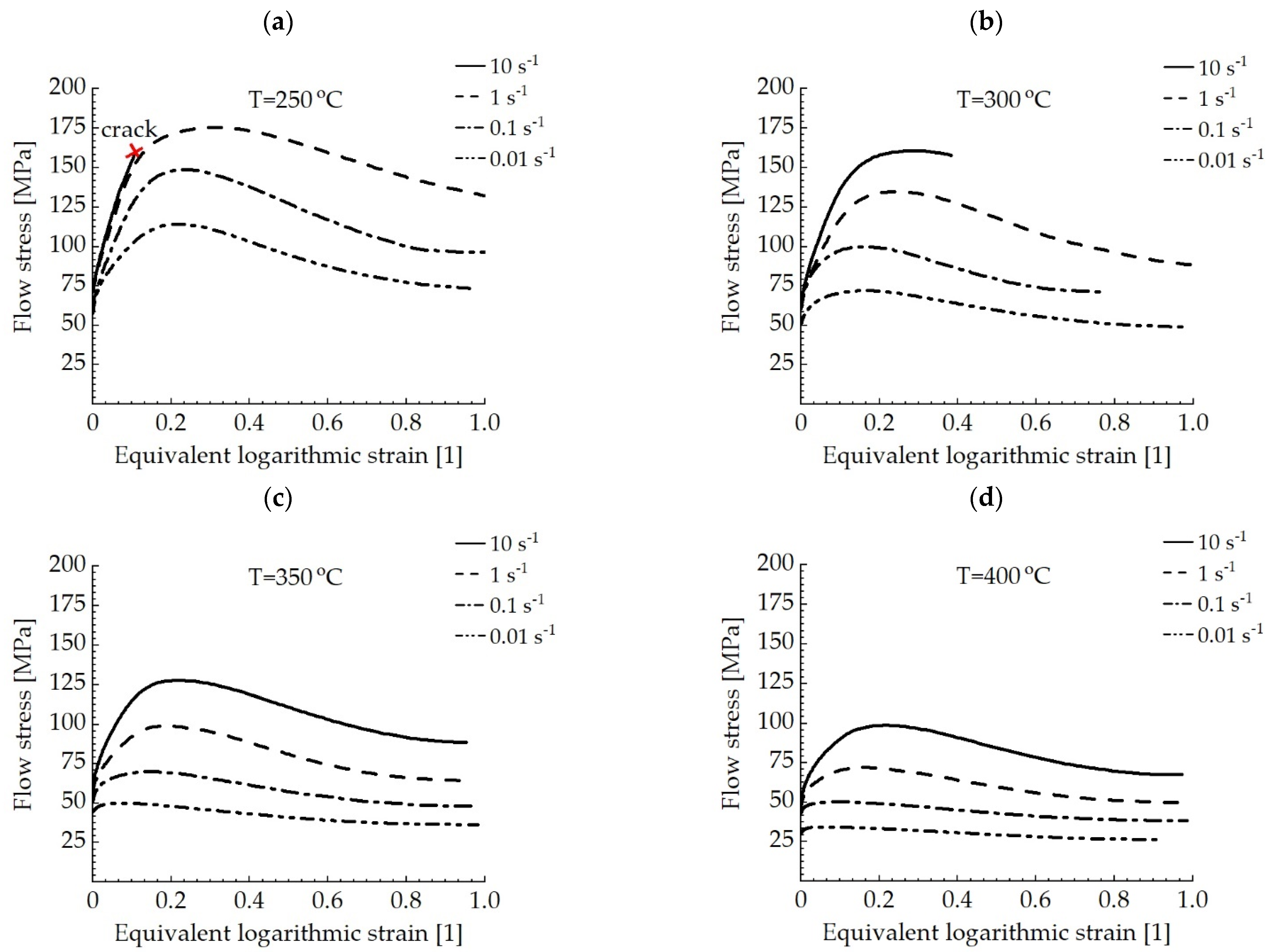
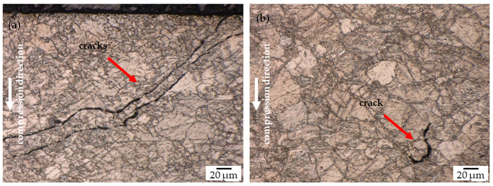
3.3. Hot Forming Behaviour of Twin-Roll Cast and Annealed Alloy

Figure 7 shows the flow curves of the twin-roll cast and heat-treated magnesium alloy AZ31, within ranges of temperature from 250 to 400 °C and the forming speeds from 0.01 to 10 s−1. One representative curve from each of the multiple trials is shown in the diagrams.
The majority of the flow curves show a typical development due to the influence of temperature and forming speed. As expected, the yield stress drops at higher temperatures and lower forming speeds. This can be attributed to the dislocations that increases with the forming speed and thus hinders the dislocation movement, which leads to the increase of the yield stress. Furthermore, the higher forming temperatures lead to an easier sliding of the basal slip plane of the magnesium matrix due to the low accumulated critical shear stress. Most of the curves show a steady increase followed by a flat decrease of the flow stresses. That indicates the mechanisms of dynamic recovery and recrystallization during forming. The flow curve at 250 °C and a forming speed of 10 s−1 could not be fully tested because of material failure due to cracking (Figure 7a). Additionally, at a forming temperature of 300 °C and a forming speed of 10 s−1, only the development up to a logarithmic forming degree of 0.4 is considered. Despite repeated testing, in the higher forming range, the curves deviate. Also, the dynamic recovery and recrystallization are weakly pronounced in the flow curves at 400 °C and low forming speeds (0.1 and 0.01 s−1) (Figure 7d).

4. Discussion

4.1. Microstructure of Twin-Roll Cast and Annealed Alloy

The typical twinning of magnesium alloys [13,14,15,16] can be confirmed in the twin-roll cast state (see Figure 3, top right) according to the publication of Zhi et al. (2019) [17]. In addition to a large number of twins, coarse grains and isolated dynamically recrystallized grains could be detected in the twin-roll cast AZ31 magnesium strip. The twinning mechanism was also observed in other magnesium alloys. Similar behaviour was found by Wang et al. (2010) [18], who compared the zinc-containing magnesium alloy ZK60 in the conventional direct as-casted and as-rolled conditions. Furthermore, irregularities such as segregation can occur in twin-roll cast magnesium-aluminum-zinc alloys (AZ alloy system), which must be avoided to achieve high component qualities. As the twin-roll cast wire passes through the rolls, the presence of the mushy zone can influence the degree of segregation [19,20,21].
A heat treatment reduces the amount of segregation in the twin-rolled cast magnesium wire pre-profile (460 °C/15 min). Similarly, within the investigations by Aljarrah et al. (2011) [22], heat treatment (400 °C/1 h) significantly reduced the amount of centerline segregation detected in a twin-roll cast AZ31 strip. Analogous results were obtained by Kawalla et al. (2011) [23]. The twin-roll cast and heat-treated AZ31 magnesium strip forms globulitic grains with a mean grain diameter of 22 μm. Microprobe analysis confirmed a more uniform element distribution. Thus, it can be summarized that cold forming mechanisms, such as twinning, can occur during the twin-roll casting of magnesium wire. Heat treatments reduce segregation resulting from decompositioning effects and lead to a more homogeneous microstructure.

4.2. Hot Deformation Behaviour of Twin-Roll Cast and Annealed Alloy

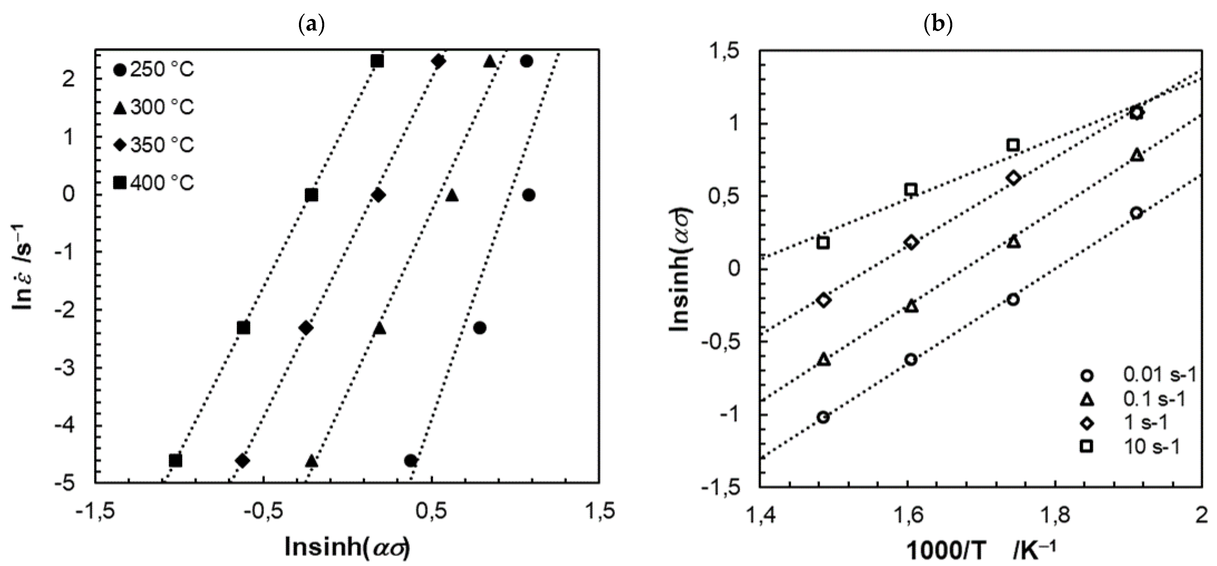
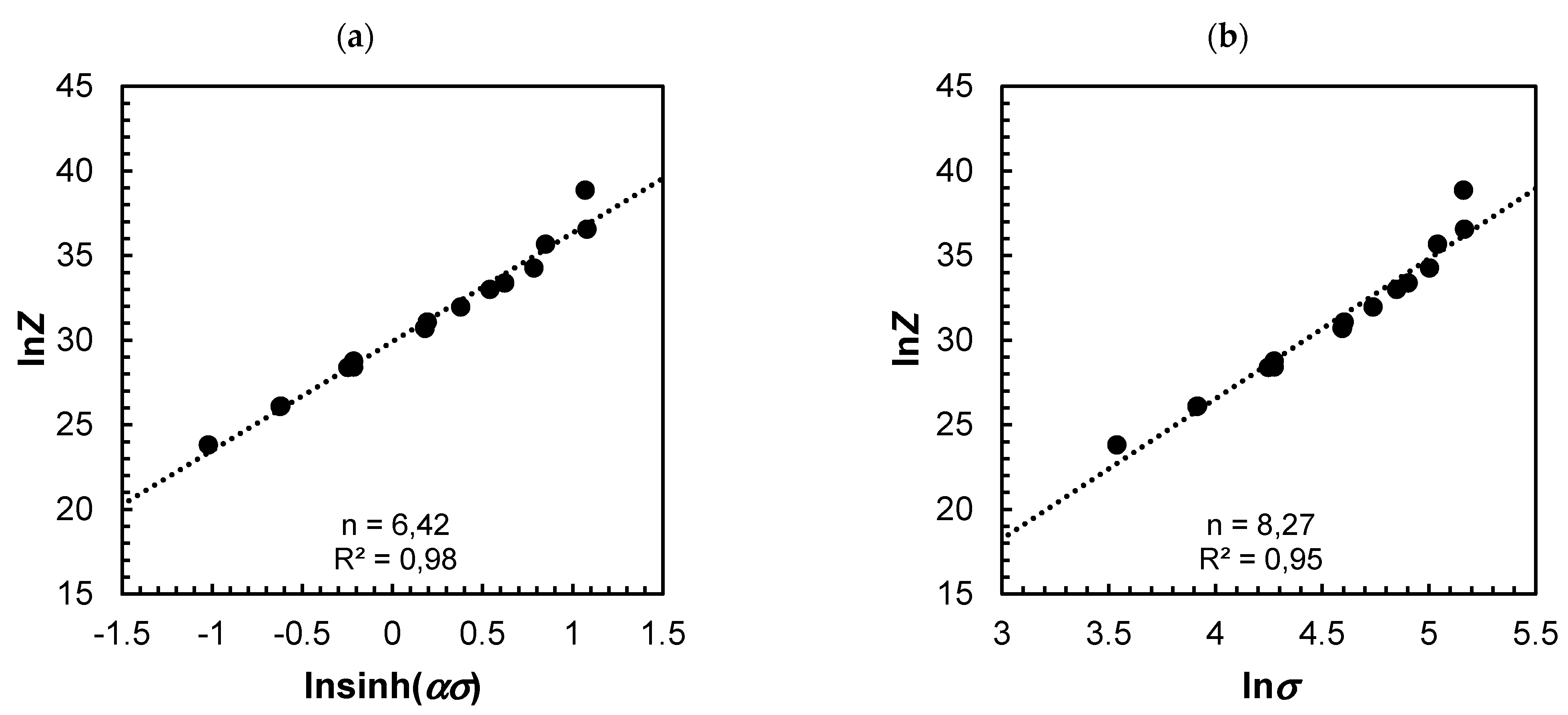
4.2.1. Analysis of Hot Compressive Deformation Behaviour

For the description of the plastic flow behaviour, the evaluation is carried out by the power dissipation efficiency η and the instability parameter ξ ε · . To summarize and present the experimentally determined data, the constitutive model of Sellars and Tegart [24,25] is proposed. With this calculation approach, the temperature and velocity during the defined deformation are considered. Equation (7) below shows the relationship:
ε · = A · [ sin h ( α σ ) ] n · Q R · T
This equation is given by the effective strain rate ε · (s−1), the thermodynamic temperature T, the speak stress σ (MPa), the average activation energy during plastic deformation Q ( kJ · mol 1 ), the ideal gas constant R ( 8.314   J · mol · K 1 ), the material constant A, the strain hardening exponent n and the fitting parameter α. The linear dependence of the flow stress on the forming temperature and rate enables the graphical determination of the average material coefficients using the slopes in the following diagrams (Figure 8, Figure 9 and Figure 10). Thus, the following values result for the range of validity from 0.01 to 10 s−1 and 250 to 400 °C:   A = 9.8945 × 10 12 , Q = 159.008   kJ · mol 1 , α = 0.010263   MPa 1 , n = 6.42.
The calculated activation energy can be initially classified in the range of dynamic recrystallization. This value varies within a range of 105 and 185 kJ · mol 1 [26,27,28,29,30,31,32]. Furthermore, the activation energy is above the self-diffusion of magnesium (135 kJ · mol 1 ) [33]. In the study by Lee et al. (2007) [31], the focus was on the flow softening behaviour during forming (upset test: 250–500 °C, 10−4–102 s−1) of a rolled AZ31B magnesium alloy. Here, an activation energy of 152   kJ · mol 1 could be calculated. Based on dynamic recrystallization, the microstructural evolution is attributed to the softening behaviour. The investigations of Beer et al. (2002) [34] led to similar results in which, among other things, the upsetting test of the extruded magnesium alloy AZ31 was carried out (300–450 °C, 0.001–1 s−1). With a forming degree of 0.6, an activation energy of 153   kJ · mol 1 could be determined. Furthermore, the yield stresses at low forming rates are found to be strongly dependent on the load type. That explained the accumulated influence of prismatic sliding and the onset of dynamic recrystallization. In the work by Zhi et al. (2019) the hot forming behaviour on a twin-roll cast AZ31 magnesium sheet was investigated. The cylindrical upset specimens (diameter 4 mm, height 6 mm) were held at the appropriate forming temperature (200–400 °C) for about 3 min, formed (50% reduction, 0.001–1 s−1) and quenched in water. In the initial state, the magnesium alloy AZ31 has coarse grains, a large number of twins and isolated dynamically recrystallized grains, thus representing a typical rolling microstructure. Within the temperature range of 250 and 350 °C, the average activation energy is 111.601   kJ · mol 1 . This value is close to the range of lattice self-diffusion. This indicates dynamic recrystallization influenced by a controlled dislocation increase, making the basal slip system dominant. Due to the increase of the transformation temperature (350 to 400 °C), the activation energy increased to 192.304 kJ · mol 1 that enhanced strong dynamic recrystallization. In this temperature range, the forming mechanisms include the non-basic slip systems, including prismatic, pyramidal and crossslip.
To show a possible correlation between the generated data, the Zener-Hollomon parameter can be used. The influence during the hot forming can be evaluated by the comparative forming speed and the thermal activation energy. Here, the description of the dynamic microstructure development is carried out using semi-empirical approaches based on physical considerations [35]. The hyperbolic sine curve approach according to Sellars und McTegart [25] is described below (Equation (8)):
Z = A · sin h α σ n
Figure 10a shows the ln Z –lnsinh (ασ) curve with an activation energy Q = 159.008   kJ · mol 1 and the fitting parameter α = 0.010263   MPa 1 . For the range of validity from 0.01 to 10 s−1 and 250 to 400 °C the hyperbolic sinusoidal function can be approximated well and reaches a value of 98 for the linear regression (R2). Furthermore, statements can be made about the dominating forming mechanisms via the stress exponent n. Since the exponent assumes a value of 6.42 and taking into account the findings of Sherby et al. (2002) [36], in which the dislocation climb creep is present n > 5, with the solute drag creep at n = 3, it is assumed that the dominant mechanism is dislocation climb creep. This assumption is also made in the publication by Zhi et al. (2019) [17], in which the dynamic recrystallization is the disclocation climb controlled by the lattice self-diffusion. The stress exponent ranges between 6.42 and 6.87. For comparison, the relationship lnZ   ln is shown in Figure 10b, in which a linear relationship is evident (R2 = 0.95). It can be concluded that the hot forming behaviour of the twin-roll cast and heat-treated magnesium alloys can be described by the correlations of the Zener-Holomon parameter.

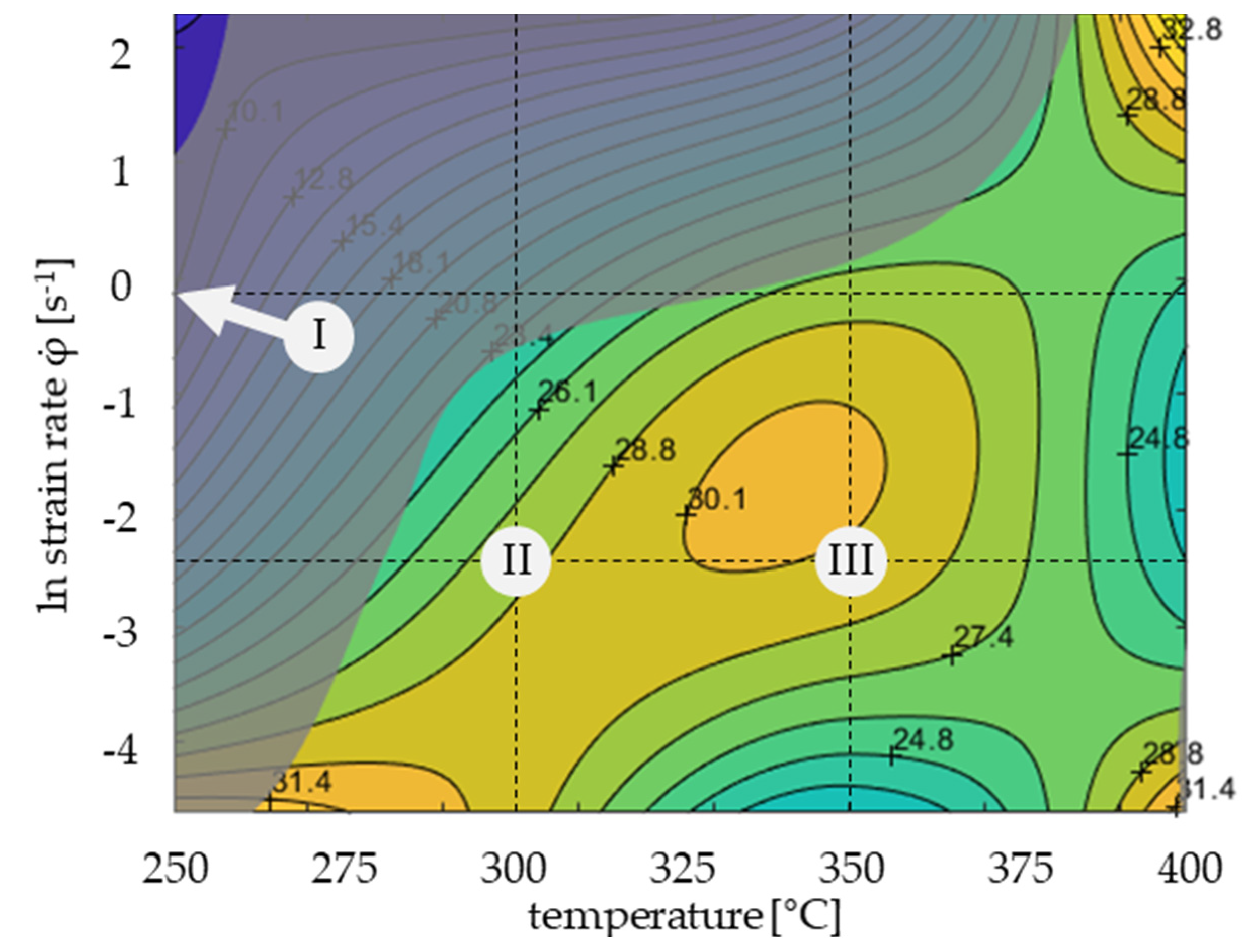
4.2.2. Processing Map

To obtain an optimal processing range for hot forming, a two-dimensional diagram consisting of isolines can be created using the experimentally determined flow curves. Hence, information on dynamic recrystallization, recovery, superplasticity, failure (cracking), formation of hard particles and deformation bands can be derived [8]. The processing map for the twin-roll cast and heat-treated AZ31 magnesium wire pre-profile section is shown below in Figure 11.
The logarithmic strain here reaches a value of 0.4, which is representative of a hot rolling pass [37,38]. Along the geometry, the loss efficiency η is plotted as a percentage, the grey domain indicates the instability ( ξ ε ·   <   0 )). Due to the limited amount of data, the domain and the environment are considered with a loss efficiency of 30.1%. Since magnesium is one of the materials with a low stacking energy, it can be assumed that dynamic recrystallization occurs from a loss efficiency of 30 to 40% [8]. The instability range starts at 250 °C and 3.25 s−1 (ln strain rate 1,18 s−1), initially extends up to a forming speed of 0.01 s- 1 and at high speeds (1–10 s−1) covers a temperature range from 300 °C to 380 °C. Exemplary for this range is point I in Figure 12 (250 °C, 1 s−1). Figure 12a shows a crack that extends over the entire section. Figure 12b also shows a crack in the 1/6 area of the sample, where a deformation of about 0.4 is observed. It can be seen here that the crack appears along the grain boundaries, thus indicating intercrystalline cracking. The cracks that appear spread along the grain boundaries during forming when low-melting compounds form due to segregation of certain alloying additions. At medium temperatures, which are generally encountered during creep (forming at slow rates), intercrystalline cracking is a typical failure mode. Furthermore, adiabatic shear bands can occur in the instability range at higher forming speeds [8].
Since the activation energy indicates dynamic recrystallization and that also has been observed in this temperature range in some publications [13,17,39], points II and III are considered as examples.
In point II, the deformation was carried out at 300 °C and a forming speed of 0.01 s−1 (see Figure 13a). Two recrystallization mechanisms are evident in the microstructure shown. On the one hand, discontinuous dynamic recrystallization (DDRX) occurs. DDRX is mainly found in materials with low stacking fault energy and is characterized by the formation and movement of large-angle grain boundaries [40]. A striking feature of this form is the formation of necklace structure, where small, recrystallized grains are arranged along the original grain boundaries. The mechanism of DDRX is interrupted when the recrystallized grains collide [28,41,42,43]. Furthermore, twinning-induced dynamic recrystallization (TDRX) can be observed in this image. According to existing publications, the recrystallization nuclei can occur at twin boundaries [26] and within twins [13,44,45,46,47]. Figure 14 and Figure 15 show the two described dynamic recrystallisation effects in more detail in the form of an EBSD measurement.
Point III within the process map is very close to the loss efficiency region. Here, the cylinder compression test was carried out at 350 °C and a forming speed of 0.01 s−1. The associated microstructure development shows Figure 13b. In this micrograph, it is noticeable that along the grain boundaries is a higher amount of subgrains that formed. This dynamic recrystallization mechanism is called continuous dynamic recrystallization (CDRX) and starts at the grain and twin boundaries, where dislocations accumulate, leading to an increased dislocation density locally. The rearrangement of lattice dislocations from different slip systems can lead to the formation of small angle grain boundaries. Thus, this mechanism takes place without direct nucleation and without movement of the large-angle grain boundaries. The high dislocation densities occur predominantly near large-angle grain boundaries, resulting in the formation of a majority of subgrains at the shell regions of the original grains [13,40,41,46,48,49]. EBSD measurement for the CDRX is shown in Figure 16.
Based on the generated processing map, the recommended optimum forming range is from 325 to 355 °C and 0.0907 to 0.3678 s−1. Concerning the literature that was used and the exemplary microstructure images, during hot forming, dynamic recrystallization mechanisms are expected.

5. Conclusions

In the present work, the deformation behaviour of an AZ31 wire pre-profile produced at the pilot plant for magnesium twin-roll casting wire of the IMF was investigated for the first time. A centrally formed segregation zone and an inhomogeneous microstructure characterize the initial state. The central area was embossed with a fine-grained microstructure; meanwhile, a coarser grain appeared in the peripheral area. Heat treatment at 460 °C for 15 min reduced the centre segregation and caused a slight grain coarsening. After the heat treatment, the microstructure was more homogeneous compared to the twin-roll cast condition. Flow curves were recorded using the cylinder compression test and showed a typical dependence on temperature and forming speed. The curves show a steady increase and flat decrease of the yield stress, the mechanism of dynamic recovery and recrystallization can be construed as the predominant deformation mechanism. Likewise, the calculated activation energy ( 159.008   kJ · mol 1 ) can be classified in the range of dynamic recrystallization. To determine the optimal process parameters, a processing map was created at an equivalent logarithmic strain of 0.4. Three mechanisms for recrystallization were identified: discontinuous dynamic recrystallization (DDRX), twinning-induced dynamic recrystallization (TDRX) and continuous dynamic recrystallization (CDRX). Furthermore, an instability range at 250 to 375 °C and at forming speeds from 0.01 to 10 s−1 is striking. Intercrystalline cracking was observed in this area. Based on the processing map, the optimal working range of 325 to 355 °C and 0.0907 to 0.3678 s−1 is recommended.

Author Contributions

Conceptualization, S.B. and F.A.; methodology, S.B. and F.A.; formal analysis, F.A.; investigation, M.M., S.B. and F.A.; data curation, F.A.; writing—original draft preparation, F.A.; writing—review and editing, M.U. and U.P.; supervision, F.A.; project administration, U.P.; All authors have read and agreed to the published version of the manuscript.

Funding

The research was carried out within the framework of the “Development of twin-roll casting technology for magnesium pre-wire profiles” project. The project is funded by the European Union (European Regional Development Fund) and the Free State of Saxony.
Crystals 12 00173 i001

Institutional Review Board Statement

Not applicable.

Informed Consent Statement

Not applicable.

Data Availability Statement

Not applicable.

Conflicts of Interest

The authors declare no conflict of interest.

References

  1. Mordike, B.L.; Ebert, T. Magnesium: Properties—Applications—Potential. Mater. Sci. Eng. A 2001, 302, 37–45. [Google Scholar] [CrossRef]
  2. Luo, A.A. Applications: Aerospace, automotive and other structural applications of magnesium. In Fundamentals of Magnesium Alloy Metallurgy; Woodhead Publishing: Sawston, UK, 2013; pp. 266–316. [Google Scholar]
  3. Neh, K.; Ullmann, M.; Oswald, M.; Berge, F.; Kawalla, R. Twin roll casting and strip rolling of several magnesium alloys. Mater. Today Proc. 2015, 2, S45–S52. [Google Scholar] [CrossRef]
  4. Kawalla, R.; Ullman, M. Magnesium sheet production–state and perspectives. Obróbka Plast. Metali 2006, 17, 21–26. [Google Scholar]
  5. Gunter, L.; Rudolf, K.; Matthias, O.; Michael, S. Verfahren zum Gießwalzen von Magnesiumdrähten Patent DE102012209568, 14 January 2016. Available online: https://patentimages.storage.googleapis.com/2b/f9/6a/d06d9da1341e94/DE102012209568A1.pdf (accessed on 11 July 2021).
  6. Moses, M.; Kawalla, C.; Kawalla, R.; Höck, M. Development of an Innovative and Quality-Focused Production Technology for Magnesium Wire. In Materials Science Forum; Trans Tech Publications Ltd.: Zurich, Switzerland, 2018; Volume 918, pp. 34–39. [Google Scholar]
  7. Wemme, H.; Moses, M.; Oswald, M.; Ullmann, M.; Kawalla, R.; Prahl, U. Anwendung des innovativen Gießwalzverfahrens zur wirtschaftlichen Herstellung von Magnesium-Langprodukten. 10. Ranshofener Leichtmetalltage. In Hochleistungsmetalle und Prozesse für den Leichtbau der Zukunft; LKR-Verlag: Ranshofen, Austria, 2018; pp. 113–123. [Google Scholar]
  8. Prasad, Y.V.R.K.; Rao, K.P.; Sasidhara, S. Hot Working Guide. A Compendium of Processing Maps; ASM International: Geauga County, OH, USA, 2015. [Google Scholar]
  9. Moses, M.; Ullmann, M.; Kawalla, R.; Prahl, U. Improving Mechanical Properties of Twin-Roll Cast AZ31 by Wire Rolling. Mater. Sci. Forum 2021, 1016, 957–963. [Google Scholar] [CrossRef]
  10. Moses, M.; Wemme, H.; Ullmann, M.; Kawalla, R.; Prahl, U.; Moses, M.; Wemme, H.; Ullmann, M.; Kawalla, R.; Prahl, U. Twin-roll casting of magnesium wire: An innovative continuous production route. In Proceedings of the 28th International Conference on Metallurgy and Materials, Brno, Czech Republic, 22–24 May 2019; pp. 438–443. [Google Scholar]
  11. Bachmann, F.; Hielscher, R.; Schaeben, H. Texture Analysis with MTEX–Free and Open Source Software Toolbox. Solid State Phenom. 2010, 160, 63–68. [Google Scholar] [CrossRef] [Green Version]
  12. Pawar, S.; Zhou, X.; Hashimoto, T.; Thompson, G.E.; Scamans, G.; Fan, Z. Investigation of the microstructure and the influence of iron on the formation of Al8Mn5 particles in twin roll cast AZ31 magnesium alloy. J. Alloys Compd. 2015, 628, 195–198. [Google Scholar] [CrossRef]
  13. Zhang, Z.; Wang, M.-p.; Li, Z.; Jiang, N.; Hao, S.; Gong, J.; Hu, H. Twinning, dynamic recovery and recrystallization in the hot rolling process of twin-roll cast AZ31B alloy. J. Alloys Compd. 2011, 509, 5571–5580. [Google Scholar] [CrossRef]
  14. Guan, L.; Tang, G.; Jiang, Y.; Chu, P.K. Texture evolution in cold-rolled AZ31 magnesium alloy during electropulsing treatment. J. Alloys Compd. 2009, 487, 309–313. [Google Scholar] [CrossRef]
  15. Barnett, M.R. Twinning and the ductility of magnesium alloys: Part II. “Contraction” twins. Mater. Sci. Eng. A 2007, 464, 8–16. Available online: https://www.sciencedirect.com/science/article/pii/S0921509306026876 (accessed on 29 November 2021). [CrossRef]
  16. Barnett, M.R. Twinning and the ductility of magnesium alloys. Mater. Sci. Eng A 2007, 464, 1–7. Available online: https://www.sciencedirect.com/science/article/pii/S0921509307004297 (accessed on 29 November 2021). [CrossRef]
  17. Zhi, C.; Ma, L.; Jia, W.; Huo, X.; Fan, Q.; Huang, Z.; Le, Q.; Lin, J. Dependence of deformation behaviors on temperature for twin-roll casted AZ31 alloy by processing maps. J. Mater. Res. Technol. 2019, 8, 5217–5232. [Google Scholar] [CrossRef]
  18. Wang, S.-r.; Wang, M.; Kang, S.-b.; Cho, J.-h. Microstructure comparison of ZK60 alloy under casting, twin roll casting and hot compression. Trans. Nonferrous Met. Soc. China 2010, 20, 763–768. [Google Scholar] [CrossRef]
  19. Bae, J.H.; Shim, M.S.; Suh, B.C.; Kim, D.W.; Park, S.H.; Kim, N.J. Segregation in twin-roll cast Mg alloy and its suppression through alloy design. Mater. Lett. 2014, 132, 361–364. [Google Scholar] [CrossRef]
  20. Kim, J.J.; Park, W.-J.; Choo, D. Microstructural Analysis of Segregated Area in Twin Roll Cast Mg Alloy Sheet; Research Institute of Industrial Science and Technology (RIST): Pohang, Korea, 2011; pp. 147–150. [Google Scholar]
  21. Park, S.S.; Park, W.-J.; Kim, C.H.; You, B.S.; Kim, N.J. The twin-roll casting of magnesium alloys. JOM 2009, 61, 14–18. [Google Scholar] [CrossRef]
  22. Aljarrah, M.; Essadiqi, E.; Kang, D.H.; Jung, I.H. Solidification Microstructure and Mechanical Properties of Hot Rolled and Annealed Mg Sheet Produced through Twin Roll Casting Route. Mater. Sci. Forum 2011, 690, 331–334. [Google Scholar] [CrossRef]
  23. Kawalla, R.; Ullmann, M.; Schmidt, C.; Dembińska, J.; Vogt, H.P. Properties of Magnesium Strips Produced by Twin-Roll-Casting and Hot Rolling. Mater. Sci. Forum 2011, 690, 21–24. [Google Scholar] [CrossRef]
  24. Sellars, C.M.; Tegart, W.J.M. Hot Workability. Int. Metall. Rev. 1972, 17, 1–24. [Google Scholar] [CrossRef]
  25. Sellars, C.M.; McTegart, W.J. On the mechanism of hot deformation. Acta Metall. 1966, 14, 1136–1138. [Google Scholar] [CrossRef]
  26. Barnett, M.R. Hot working microstructure map for magnesium AZ31. Mater. Sci. Forum 2003, 426, 515–520. [Google Scholar] [CrossRef]
  27. Barnett, M.R. Recrystallization during and following hot working of magnesium alloy AZ31. Mater. Sci. Forum 2003, 419, 503–508. [Google Scholar] [CrossRef]
  28. Spigarelli, S.; Mehtedi, M.E.; Cabibbo, M.; Evangelista, E.; Kaneko, J.; Jäger, A.; Gartnerova, V. Analysis of high-temperature deformation and microstructure of an AZ31 magnesium alloy. Mater. Sci. Eng. A 2007, 462, 197–201. [Google Scholar] [CrossRef]
  29. Prasad, Y.; Rao, K.P. Processing maps for hot deformation of rolled AZ31 magnesium alloy plate: Anisotropy of hot workability. Mater. Sci. Eng. A 2008, 487, 316–327. [Google Scholar] [CrossRef]
  30. Poletti, C.; Dieringa, H.; Warchomicka, F. Local deformation and processing maps of as-cast AZ31 alloy. Mater. Sci. Eng. A 2009, 516, 138–147. [Google Scholar] [CrossRef]
  31. Lee, B.H.; Reddy, N.S.; Yeom, J.T.; Lee, C.S. Flow softening behavior during high temperature deformation of AZ31Mg alloy. J. Mater. Process. Technol. 2007, 187, 766–769. [Google Scholar] [CrossRef]
  32. Guo, Q.; Yan, H.G.; Zhang, H.; Chen, Z.H.; Wang, Z.F. Behaviour of AZ31 magnesium alloy during compression at elevated temperatures. Mater. Sci. Technol. 2005, 21, 1349–1354. [Google Scholar] [CrossRef]
  33. Gottstein, G. Physikalische Grundlagen der Materialkunde; Springer: Berlin/Heidelberg, Germany, 2007. [Google Scholar]
  34. Beer, A.G.; Barnett, M.R. The hot working flow stress and microstructure in magnesium AZ31. In Essential Readings in Magnesium Technology; Springer: Berlin/Heidelberg, Germany, 2016; pp. 369–374. [Google Scholar]
  35. Johnson, W.A. Reaction kinetics in processes of nucleation and growth. Am. Inst. Min. Metal. Petro. Eng. 1939, 135, 416–458. [Google Scholar]
  36. Sherby, O.D.; Taleff, E.M. Influence of grain size, solute atoms and second-phase particles on creep behavior of polycrystalline solids. Mater. Sci. Eng. A 2002, 322, 89–99. [Google Scholar] [CrossRef]
  37. Ullmann, M.; Schmidtchen, M.; Kittner, K.; Henseler, T.; Kawalla, R.; Prahl, U. Hot Deformation Behaviour and Processing Maps of an as-Cast Mg-6.8Y-2.5Zn-0.4Zr Alloy. Mater. Sci. Forum 2019, 949, 57–65. [Google Scholar] [CrossRef] [Green Version]
  38. Kittner, K.; Ullmann, M.; Henseler, T.; Kawalla, R.; Prahl, U. Microstructure and Hot Deformation Behavior of Twin Roll Cast Mg-2Zn-1Al-0.3Ca Alloy. Materials 2019, 12, 1020. [Google Scholar] [CrossRef] [Green Version]
  39. Fatemi-Varzaneh, S.M.; Zarei-Hanzaki, A.; Beladi, H. Dynamic recrystallization in AZ31 magnesium alloy. Mater. Sci. Eng. A 2007, 456, 52–57. [Google Scholar] [CrossRef]
  40. Liu, Z.-M.; Xing, S.-M.; Bao, P.-W.; Nan, L.I.; Yao, S.-Q.; Zhang, M.-L. Characteristics of hot tensile deformation and microstructure evolution of twin-roll cast AZ31B magnesium alloys. Trans. Nonferrous Met. Soc. China 2010, 20, 776–782. [Google Scholar] [CrossRef]
  41. Peng, W.P.; Li, P.J.; Zeng, P.; Lei, L.P. Hot deformation behavior and microstructure evolution of twin-roll-cast Mg–2.9 Al–0.9 Zn alloy: A study with processing map. Mater. Sci. Eng. A 2008, 494, 173–178. [Google Scholar]
  42. Tan, J.C.; Tan, M.J. Dynamic continuous recrystallization characteristics in two stage deformation of Mg–3Al–1Zn alloy sheet. Mater. Sci. Eng. A 2003, 339, 124–132. [Google Scholar] [CrossRef]
  43. Ion, S.E.; Humphreys, F.J.; White, S.H. Dynamic recrystallisation and the development of microstructure during the high temperature deformation of magnesium. Acta Metall. 1982, 30, 1909–1919. [Google Scholar] [CrossRef]
  44. Al-Samman, T.; Gottstein, G. Dynamic recrystallization during high temperature deformation of magnesium. Mater. Sci. Eng. A 2008, 490, 411–420. [Google Scholar] [CrossRef]
  45. Liang, S.; Okrutny, P.; Wang, X.; Zurob, H. Recrystallization nucleation sites in deformed AZ31. In Proceedings of the Mg2012: 9th International Conference on Magnesium Alloys and their Applications, Vancouver, BC, Canada, 8–12 July 2012; Volume 9, pp. 663–668. [Google Scholar]
  46. Sitdikov, O.; Kaibyshev, R. Dynamic recrystallization in pure magnesium. Mater. Trans. 2001, 42, 1928–1937. [Google Scholar] [CrossRef] [Green Version]
  47. Wang, M.; Xin, R.; Wang, B.; Liu, Q. Effect of initial texture on dynamic recrystallization of AZ31 Mg alloy during hot rolling. Mater. Sci. Eng. A 2011, 528, 2941–2951. [Google Scholar] [CrossRef]
  48. Pérez-Prado, M.T.; Del Valle, J.A.; Contreras, J.M.; Ruano, O.A. Microstructural evolution during large strain hot rolling of an AM60 Mg alloy. Scr. Mater. 2004, 50, 661–665. [Google Scholar] [CrossRef]
  49. Yang, X.-Y.; Ji, Z.-S.; Miura, H.; Sakai, T. Dynamic recrystallization and texture development during hot deformation of magnesium alloy AZ31. Trans. Nonferrous Met. Soc. China 2009, 19, 55–60. [Google Scholar] [CrossRef]
Figure 1. (a) Principle of the twin-roll casting process [7], (b) sample collection from wire pre-profile for compression test at quenching and forming dilatometer.
Crystals 12 00173 g001
Figure 2. Formed oval cross-section of the magnesium wire pre-profile (AZ31); red markings indicate the burrs formed double-sided on the upper side of the wire.
Crystals 12 00173 g002
Figure 3. Twin-roll cast initial condition in longitudinal view, (a) general view (red arrows show segregations), (b) detailed image from the upper edge, from the middle and from the lower edge, red markings and arrows show exemplary precipitates and twins, (c) EBSD measurement peripheral zone with a detailed twin and (d) EDS measurement wire centre.
Crystals 12 00173 g003
Figure 4. Grain size distribution of the twin-roll cast magnesium wire pre-profile AZ31, (a) peripheral zone and (b) wire centre.
Crystals 12 00173 g004
Figure 5. Twin-roll cast and heat-treated condition in longitudinal view, (a) general view (segregations almost completely reduced), (b) detailed view from the upper edge (grain refinement), from the centre (precipitations) and from the lower edge (grain refinement), (c) EBSD measurement peripheral zone and (d) EDS measurement centre area of wire.
Crystals 12 00173 g005
Figure 6. Grain size distribution of the twin-roll cast and heat-treated (460 °C/15 min) magnesium wire pre-profile AZ31, (a) edge area and (b) wire centre.
Crystals 12 00173 g006
Figure 7. Flow curves of twin-roll cast and heat-treated magnesium alloy AZ31 at different forming speeds and temperatures: ((a) 250 °C, (b) 300 °C, (c) 350 °C and (d) 400 °C).
Crystals 12 00173 g007
Figure 8. Relationship between ln ε and (a) ln σ (b) σ .
Crystals 12 00173 g008
Figure 9. Relationship between of (a) lnε–ln[sinh(ασ)] and (b) ln[sinh(ασ)]–1/T at different strain rates.
Crystals 12 00173 g009
Figure 10. Relationship between (a) lnZ–ln[sinh(α∙σ)] and (b) lnZ–ln𝜎.
Crystals 12 00173 g010
Figure 11. Processing map for twin-roll cast and annealed (460 °C/15 min) AZ31 at an equivalent logarithmic strain of 0.4.
Crystals 12 00173 g011
Figure 12. Light optical micrograph (1000×) of the formed (250 °C, 1 s−1) AZ31 magnesium alloy (point I), (a) crack formation in the upper sample edge, (b) crack formation along the grain boundary (1/6 position).
Crystals 12 00173 g012
Figure 13. Light optical micrograph (1000×) of the transformed AZ31 magnesium alloy (1/6 position), (a) point II (300 °C, 0.01 s−1): Necklace and TDRX, (b) Point III (350 °C, 0.01 s−1): CDRX.
Crystals 12 00173 g013
Figure 14. EBSD measurement of the transformed AZ31 magnesium alloy point II (300 °C, 0.01 s−1): necklace along the grain boundaries, typical DDRX.
Crystals 12 00173 g014
Figure 15. EBSD measurement of the transformed AZ31 magnesium alloy point II (300 °C, 0.01 s−1): former twins that recrystallized, typical TDRX.
Crystals 12 00173 g015
Figure 16. EBSD measurement of the transformed AZ31 magnesium alloy Point III (350 °C, 0.01 s−1): area into which the structure is continuously dynamically recrystallized, typical CDRX.
Crystals 12 00173 g016
Table 1. Chemical composition of the AZ31 ingots in wt.% [9].
ElementAlZnMnMg
Average2.61.10.495.9
Publisher’s Note: MDPI stays neutral with regard to jurisdictional claims in published maps and institutional affiliations.

