1. Introduction
Magnesium-based alloys are marked for their low density, vibration damping, and biocompatibility. However, their strength and recovery to initial shape and size post damage/deformation are the most important shortcoming of this exotic material [
1]. In addition, in the present day, due to its biocompatibility and light weight, the use of magnesium in engineering applications is being widely explored. On the other hand, Nickel-Titanium (NiTi) shape memory alloy has attracted the attention of material scientists due to its biocompatibility, super-elasticity, shape memory effect, resilience, and vibration damping characteristics [
2,
3]. The applications of NiTi shape memory alloy encapsulate the electronics, biomedical engineering, automobile, and aerospace sectors [
4]. Incorporation of NiTi into metal matrix systems can open new avenues to expand applications, such as in high actuation energy systems, vibration and noise reduction, biomedical devices, impact resistant, and self-healing structures. Products made from NiTi for the aforementioned applications are required in diverse shapes, size, and throughput rates, and this involves significant cost, due to which its use is mainly limited to high end applications. The use of NiTi powder as reinforcement in metal matrix composites can offer significant cost benefits. The processing of such materials via friction stir processing (FSP) provides added advantages via microstructural texture modifications [
5,
6]. The reinforcement of Mg-based materials with NiTi can synergize the advantages of the two materials and overcome the limitations of Mg in the resultant Mg-NiTi metal matrix composites (MMCs). Mg-NiTi MMCs can provide cost effective solutions for light weight, biomaterial, biomedical, vibration, and noise damping applications, etc.
The past decade has seen tremendous advance in the fabrication of MMCs through FSP. The applications of FSP have encompassed the most crucial domains of the present day, i.e., transportation, aerospace, and nuclear energy industries [
7]. This is because FSP enables (i) the solid-state processing of lightweight materials, especially Mg and Al alloys, and (ii) a high degree of chemical and micro-structural control, chemically and morphologically [
8,
9]. However, the true industrial benefit of this exceptional technology remains limited due to the difficulties in obtaining a set of process parameters that yield a defect-free processed zone. This set of process parameters involves tool rotational speed, traverse speed, plunge depth (for position controlled FSP), axial force (for force controlled FSP), tool pin radius, pin length, tool offset, shoulder diameter, type of slots (continuous, intermittent), and dimensions of slots. The process parameters are closely inter-related and often produce mutually contradicting effect on the material flow, distribution, microstructural evolution, and heat input. Excess heat softens the base material (BM) to such an extent that the metal exits the flow zone in the form of flash, causing material deficiency, leading to tunnel defects. On the other hand, insufficient heating leads to sluggish material movement and lack of consolidation, again resulting in the formation of tunnels. Notably, the latter two process parameters are not applicable for Friction Stir Welding (FSW), thereby making the control of heat and elimination of defects easier. Meanwhile, for FSP, the introduction of slots increases the complexity in the selection of optimal process parameters. Further, the temperature evolution is asymmetric about the traversing line of the tool, which also makes the material flow differently and results in a skewed shape of the processed zone macrostructure. This creates significant heterogeneity in the mixing during FSP, and thereby the role of tool offset becomes important.
Introducing tool offset is a simple way to improve weld integrity during FSW [
10]. Deng et al. [
11] were able to eliminate the material deficiency through pin offset in dissimilar FSW of AA2024 aluminium alloy and AZ31B magnesium alloy. Further, among the intermetallic compounds Al
3Mg
2 and Al
12Mg
17, having eutectic temperatures of 450 °C and 437 °C, respectively, only Al
12Mg
17 was formed because of a decrease in the welding temperature due to offset. Suppression in the formation of intermetallic compounds through tool offsetting has also been witnessed for Al-Cu dissimilar friction stir welds [
12]. The change in the in-process temperature due to tool offset has been found to improve the surface quality of FS welds [
13]. Moreover, a study by Kar et al. [
14] reports that the ternary mechanical intermixing of elements in the nugget zone is greatly influenced by the tool offset. Importantly, it is established that tool offset can play an important role in decreasing tool wear during stirring [
15]. During FSP, researchers often utilize threaded pins for vertical mixing of the reinforcement powders with the base alloys. The vertical transport of material assisted by thread facilitates better vertical blending between pin and tool shoulder. At times, multiple FSP passes are employed to homogenize the reinforcement distribution in the MMCs [
16]. Thus, it is beneficial to observe the effect of tool offset in improving particle distribution. During FSW, tool offset is known to alter the process forces beneath the pin [
17]. Such force difference aids in achieving homogenous particle distribution during FSP. In summary, the literature suggests that tool offset is an inherent FSW parameter and should be optimized to attain superior mechanical and microstructural properties [
18].
In the current study, the main aim of offsetting is the control and preferably the improvement of the distribution of reinforcement particles and minimizing defects. The improvement of distribution refers to the homogenization of reinforced particles in the matrix. Understandably, the global concentration of the additive does not change significantly upon variation in tool offset because the volume fraction of the reinforcement in the matrix remains the same, regardless of the offset. However, a wider dispersion across the processed zone varies the local concentration and inter-particle distance with the tool offset due to changes in material flow dynamics. Exploring the variation in local concentration by homogenising particle distribution was another aim of the offsetting strategy. Another important secondary objective of offsetting is to provide an effective yet simple methodology for examining the effect of multiple offset conditions. Conventionally, for each level of tool offset, a separate experiment is required which amplifies the timeline and resources when the other process parameters are also varied to achieve optimum homogenization of the reinforcement. In the presented method, multiple offset conditions are tested in a single experiment, which allows much more efficient parameter optimization for FSP. There are several benefits of the presented work. Firstly, a novel approach for the minimization of defect through the variation of tool offset. Secondly, the variation in tool offset allows additional control over the particle distribution in the stir zone, which can eliminate the need for multiple passes for homogenizing the particle distribution. It provides better visualization on how the defect varies with the change in offset. Further, the evolution of defect morphology with the tool offset can be utilized in FSP’s sister processes, such as friction stir channelling. Due to the unavailability of similar studies in the literature, it is difficult to predict how the effect of offset itself alters with the change in base metal, reinforcement materials, and other significant process parameters such as rotational speed, plunge depth, and traverse speeds.
The effect of tool offset can also be implemented for modern developments of this technique. For example, fed friction stir processing is being implemented for the extremely challenging dissimilar joining of metals and polymers [
19,
20]. Such metal–polymer based hybrid structures hold crucial importance in the fabrication of advanced aircraft [
21,
22]. Another simpler variant of FSP is termed as deformation driven metallurgy, which is employed to design graphene nanoplatelet reinforced MMCs [
23].
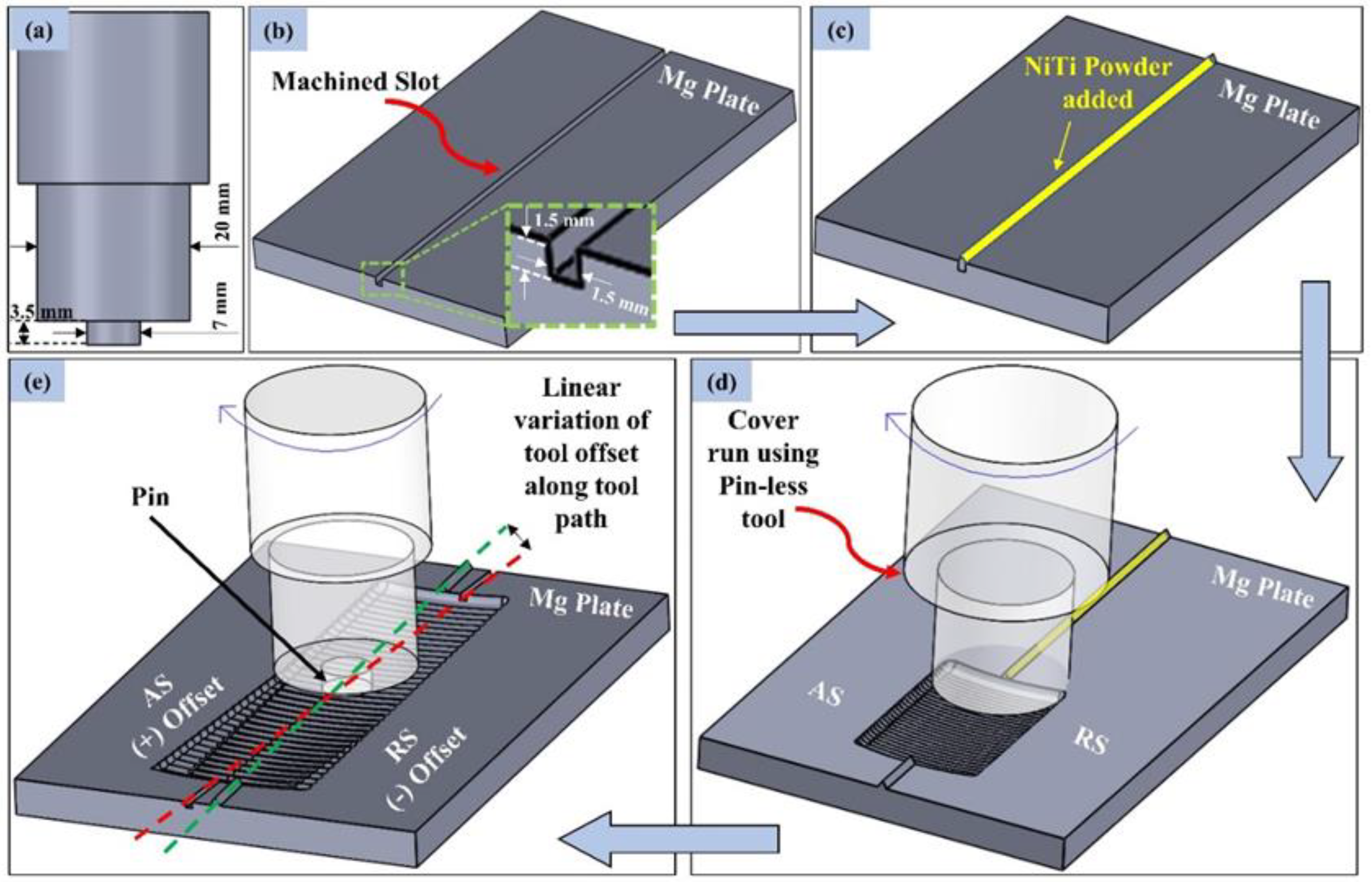
The shape of the processed zone is asymmetric about the traversing line, and the temperature on both sides of the tool, i.e., the advancing side (AS) and the retreating side (RS), is also different. During FSP, the makeup of the material being processed is heterogeneous. Further, Mg and Mg-based alloys tend to stick to the tool at process temperatures. This makes the role of tool offset very important. This parameter remains less reported, especially with respect to defect formation in Mg/Mg-based alloys. Though the probe/tool offsetting is enormously beneficial for FSW, its effect upon the defects and material flow during FSP need to be explored more extensively. The complexity associated with process parameter selection for defect-free processed zones can be obviated to a large extent by selecting an appropriate value of tool offset, which can subsequently remain as a fixed parameter in FSP. Therefore, in the present work, the effect of tool offset in FSP of Mg with NiTi shape memory alloy is investigated. For the first time, the formation of tunnelling defects and material flow has been explicated with regard to the tool offset position.
3. Results
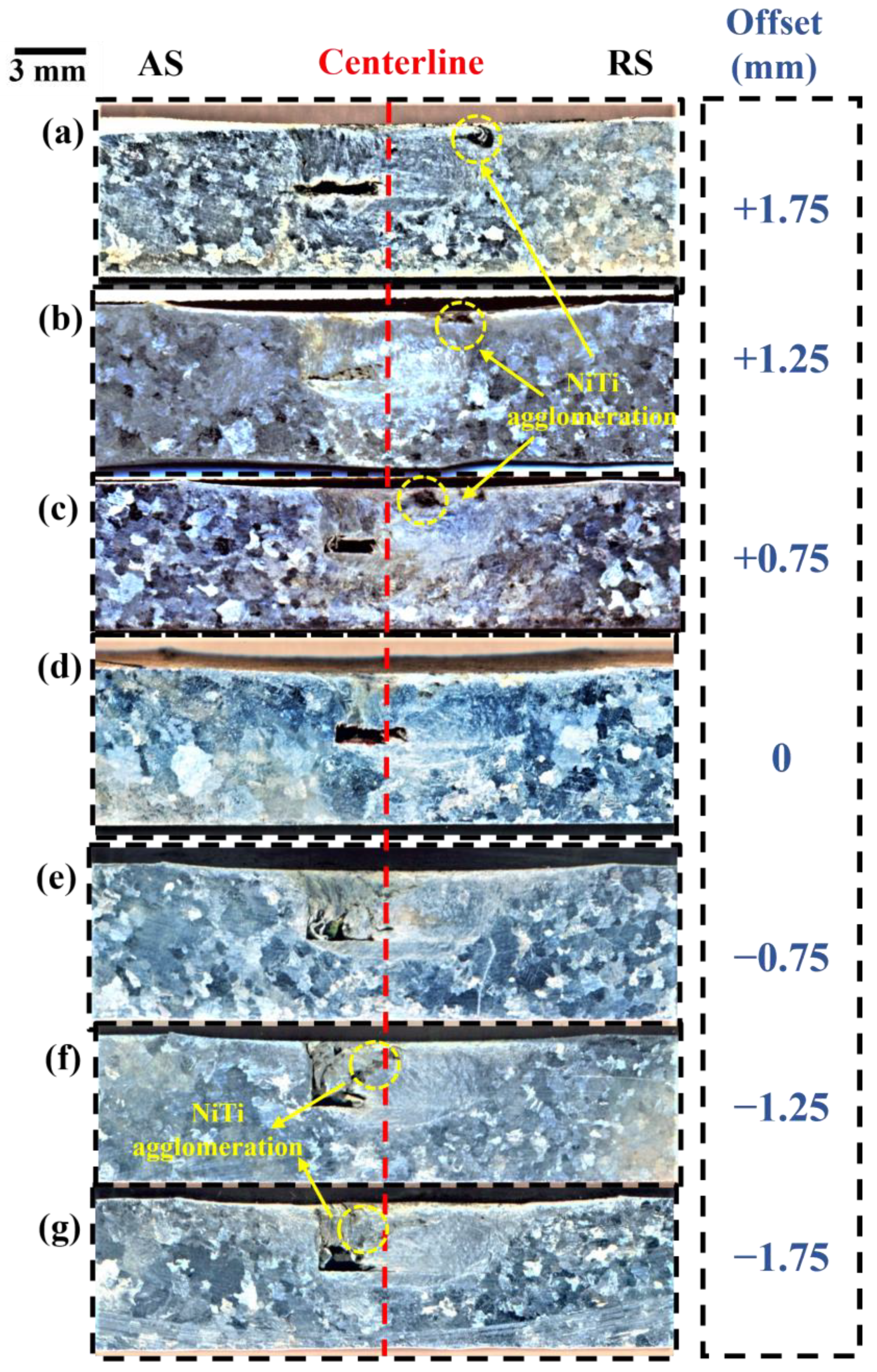
Figure 3 depicts the macrostructures of the friction stir processed regions from an offset of +1.75 mm (on AS) to −1.75 mm (on RS). A significantly large tunnelling defect was observed in the processed structure at all the offset conditions. It can be seen that the size of the tunnelling defect varies with the variation in offset, owing to the alteration in material flow and consolidation in the wake of the weld. For each of the offset conditions, i.e., on the AS or RS, the formation of tunnelling defects occurs on the AS of the processed region. However, for zero offset, a minor region of tunnelling defect can be observed in the RS of the processed zone.
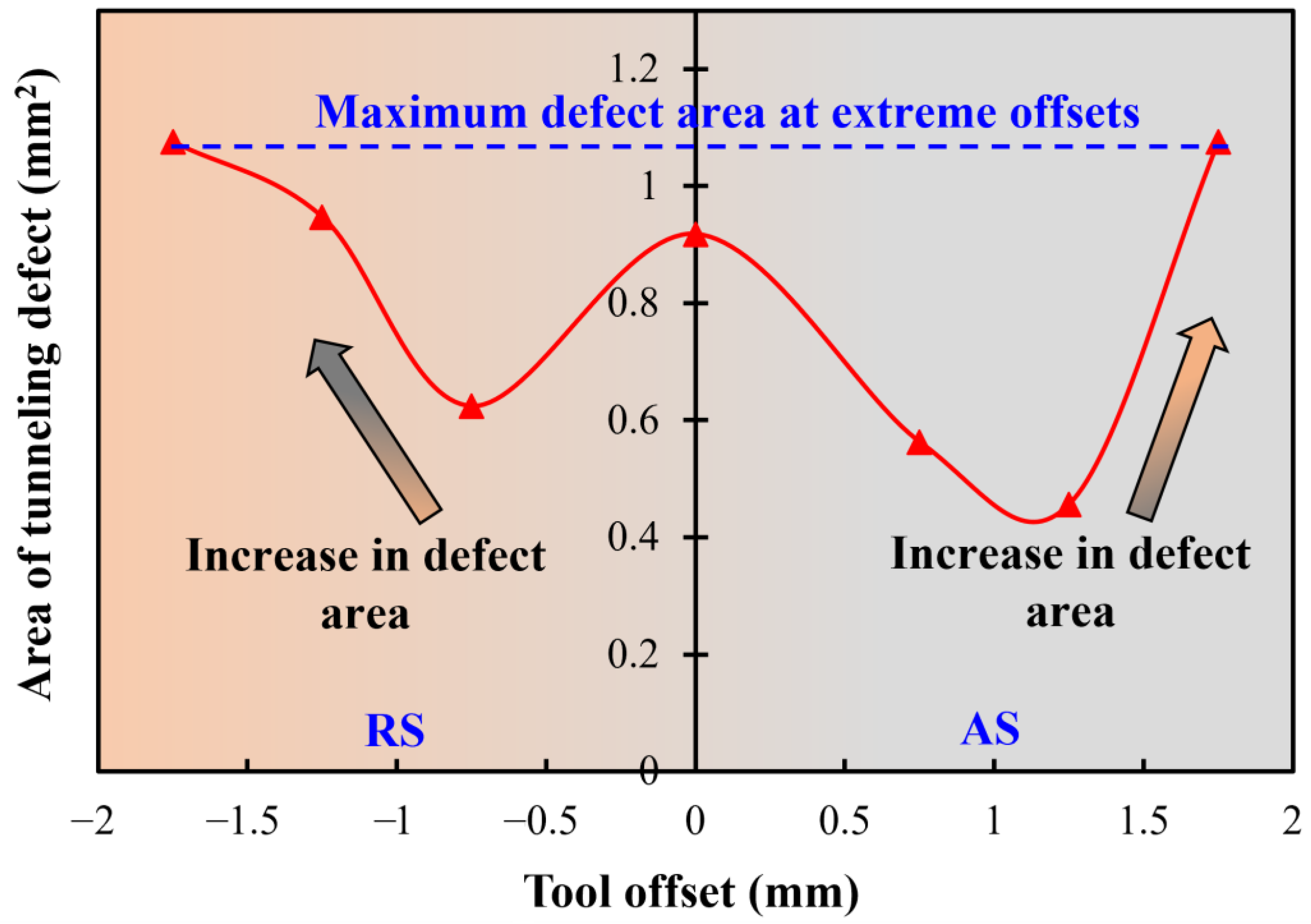
Figure 4 shows the variation of defect size (specified as defect area) with the change in offset. For negative offset conditions, the size of the defect clearly increases monotonically with the increase in the magnitude of the offset. A maximum area of the defect of ~1.1 mm
2 was seen on the extreme positive and negative offsets. Thus, for a pin of 3.5 mm diameter employed on a slot of ~1.5 mm width, increase of offset above 1.25 mm on either side leads to an increase in tunnelling defect area. The minimum defect area was observed for an AS offset condition of +1.25 mm, which is approximately 0.45 mm
2.
Apart from the location and size of the tunnelling defect, its shape also gives crucial insight into the pressure dynamics that influence the material flow.
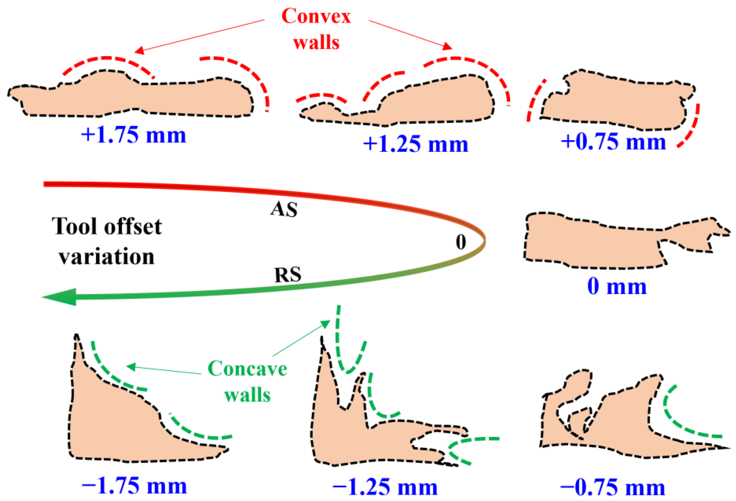
Figure 5 summarizes the magnified shape traces of the tunnelling defect at all the offset conditions. The defect morphology was obtained by tracing out the defect boundaries on highly magnified transverse section images. Interestingly, the concavity or convexity of the defect walls change with the variation in the tool offset. Hereby, to maintain consistency, the concave and convex nature is as described and seen from the outside of the defect boundaries. For the AS or positive offset conditions, the tunnelling defect walls are convex, whereas the walls show a predominantly concave behaviour in the negative or RS offset conditions. The shift from convexity to concavity of the tunnel walls is also apparent from the zero-offset position, which only begins to show the concave behaviour on the upper wall, as shown in
Figure 5. Further, the defect shape exhibits a rectangular morphology for the positive and no offset conditions, which transitions towards a triangular shape in the negative offset conditions.
The base metal Mg has a melting point of 650 °C, whereas NiTi alloy generally melts at a temperature of 1300 °C. During FSP, the stir zone (SZ) generally exhibits a temperature of ~0.6
Tm, wherein
Tm is the melting point of the base metal. The temperature of ~370–425 °C, which may prevail in the stir zone, though sufficient for the softening of Mg and reduces the flow stress, does not cause the plasticization of NiTi particles. The SZ deals the softened Mg and NiTi particles moving together. During stirring, the material from the AS is transported from ahead of the pin to the RS, thus the tool’s action on the RS is more rigorous. This may be one of the reasons that sufficient base material from the AS could not me mixed and transported during all negative offset values and the tunnels’ vertical wall coincided with the vertical wall of the slot. Further, the resulting local thermal and flow stress imbalance of the two participating materials also leads to inefficient mixing and agglomeration of NiTi in the Mg matrix. For the positive offset conditions, the NiTi particles mainly concentrate in the RS of the upper, shoulder-affected region of the SZ, as shown in
Figure 3a–c. Meanwhile, upon moving towards the negative or RS offset, there is a tendency for NiTi agglomerations to shift towards the centre of the processed regions, as observable in
Figure 3f,g. As commonly observed upon FSP, severe plastic deformation leads to dynamic recrystallization in the stir zone, whereas coarsening of grains occurs in the enclosing heat affected regions.
The tangential velocity on the AS is higher than that on the RS, which generates a peculiar gradient in the material flow and pressure.
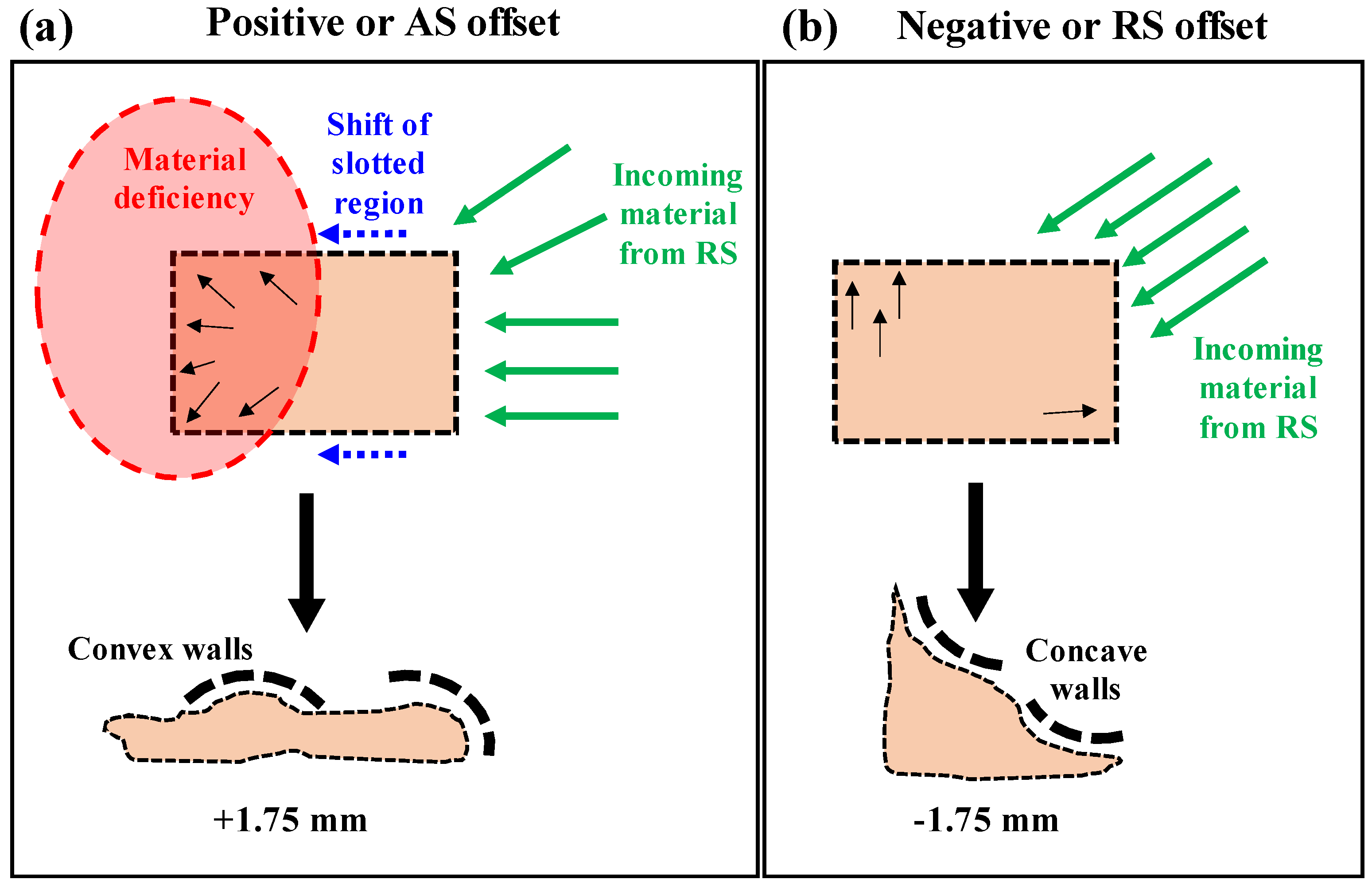
Figure 6 schematically depicts the material flow and pressure dynamics across the transverse section of the processed zone in the wake of positive and negative offset conditions. It is noteworthy that the cross-section of NiTi powder packed slot is largely rectangular after the cover run due to the plunging action of the pin-less tool. Thus,
Figure 6 depicts the powder-filled slot as having an almost rectangular shape. For the positive offset, as shown in
Figure 6a, there exists a material deficiency on the AS behind the tool because a large amount of material is picked up by the tool’s rotational action from the AS and transported to the RS through the front of the tool. As the rotating tool also traverses ahead, the transported material is further moved due to rotation and deposited from RS to AS behind the tool in the space emptied by its traverse. The material picked up on the leading side rotates with the tool and moves to the trailing end through the RS, as shown by the green arrows, and pushes the slotted region. The decrease in outward pressure results in a convex shape of the defect walls, as illustrated by the action of the black arrows. Further, as shown by the blue dashed arrows, the entire powder-filled slot also moves towards the AS, leading to wider convexity across the upper defect wall. Moreover, as observable from
Figure 5, for +1.75 mm and +1.25 mm offset conditions, the convexity is more apparent and obvious on the upper wall, because colder and harder material exists towards the bottom of the processed zone. On the other hand, for the negative offset conditions, most of the material is picked from the RS itself and no such pressure vacuum exists on the AS side. As shown in
Figure 6b, the incoming material from the leading side of the tool exerts inward force on the upper and retreating side of the slot walls, resulting in a concave shape. In addition, the AS and bottom defect walls are farther from the tool in this case and are hence colder and harder, showing minimal change of shape, which leads to a triangular morphology of the tunnelling defect.
4. Discussion
During FSP, the material travels from the leading side to the trailing side of the tool via rotation across the RS, as explicated in detail by the authors in one of the previous studies [
24]. Thus, the material at the AS has to undergo rotation by a larger degree for consolidation in the wake of the tool. The “pick-up” of the material takes place on the leading edge of the tool. The incoming material interacts with the rotating action of the tool and undergoes plastic deformation. On the RS of the leading edge, the relative velocity of the incoming material with respect to the tool is supported by the tangential velocity of the tool. This eases the flow of material on the RS, whereas on the AS of the leading edge, the tangential velocity of the tool opposes the flow of the incoming material, leading to relatively difficult rotation of the material along the periphery of the tool. Thus, the pickup of the material is relatively more difficult from the AS, in comparison to that in the RS. One point to note here is that for the +/− extreme offset values (i.e., +1.75/AS and −1.75/RS) the pin’s lateral surface aligns with the middle of the NiTi-packed slot, leaving the opposite side unaffected by the pin action directly. Interestingly, for the negative offset values, the vertical wall of the slot in the AS side forms the vertical wall of the tunnel, meaning that the pin’s action could only transport the packed NiTi from the AS to the RS and could not replenish sufficient material back to the AS, causing the void to remain in the form of a tunnel. On the contrary, for all values of offsets in the AS (including maximum offset, i.e., +1.75 mm), the pin’s action was sufficient to mix and transport the base material + NiTi from the RS adequately, but the movement of the mixture was slugging and could not be completely deposited on the AS, resulting in small tunnels in the AS. The offset of the tool in the AS is thereby suited for a wider spread of the NiTi powder with Mg matrix. Thus, the NiTi agglomerates can be seen to reach farther up the shoulder-affected stir zone for the positive AS offset conditions, as seen from
Figure 3a–c. However, for the negative or RS offset conditions, the NiTi concentrates can be seen near the stir zone centre and closer to the tunnelling defect. The macrostructure corresponding to the offset conditions of 0 mm and −0.75 mm exhibited the least agglomeration or most homogeneity in comparison to all other offset values.
In a very recent study, Bikkina et al. [
25] studied the effect of offset on AA6082/SiC MMC fabrication via FSP for two different groove designs, i.e., drilled cylindrical holes and continuous rectangular slot of the same depth. For the cylindrical holes of 1.5 mm diameter and rectangular groove of 1.5 mm width, the offset condition of 0.75 mm was compared with the conventional 0 mm offset results. For the cylindrical holes approach, the offset of 0.75 mm in RS led to a decrease in defects in comparison to the 0 mm offset. Even for the continuous groove, the offset towards RS led to a more uniform dispersion of SiC particles in the aluminium matrix. For each of the grooving approaches, the offset condition resulted in improved micro-hardness, yield stress, and ultimate tensile strength.
The process temperature during FSP is lower than the austenitic temperature of NiTi, thus the effect of NiTi on material flow is expected to be inconsequential. Because the effect of offset during FSP remains unexplored in the available literature, the studies on tool offset during FSW of dissimilar materials using interlayers can be distantly co-related with this work. The study by Kar et al. [
14] showed that the intermixing of the Al, Ti, and Cu interlayer is momentously influenced by the tool offset due to changes in the interaction of the tool with these materials. Interestingly, the formation of intermetallic compounds was also seen to vary with the tool offset.


 ,
, 


