Article

Microstructural Evolution and Mechanical Properties of 7075 Aluminium Alloy during Semi-Solid Compression Deformation

1
College of Materials Science and Engineering, Chongqing University, Chongqing 400044, China
2
State Key Laboratory of Solidification Processing, Northwestern Polytechnical University, Xi’an 710072, China
*
Author to whom correspondence should be addressed.
Crystals 2022, 12(8), 1119; https://doi.org/10.3390/cryst12081119
Submission received: 11 July 2022 / Revised: 3 August 2022 / Accepted: 5 August 2022 / Published: 10 August 2022

Abstract

:
Aluminium alloys are becoming increasingly popular due to the demands for high-performance lightweight components, and semi-solid metal processing (SSM) is a technique for forming near-net-shape and complex components with far fewer defects associated with turbulent filling. The deformation mechanisms of semi-solid 7075 aluminium alloy were studied through the direct partial re-melting method using as-extruded billets. It is found that inter-granular and intra-granular deformation occur simultaneously during compression under the semi-solid condition; the deformation of solid primary α-Al grains can compensate for the shrinkage of inter-granular liquid and increase the integrity of shaped parts. The intra-granular deformation at the final stage of SSM can change the morphology of spherical solid grains and induces sub-grain boundaries.

1. Introduction

Semi-solid metal (SSM) processing is a relatively new technique to process alloys at a temperature between the liquidus and solidus, at which the alloys exhibit unique pseudoplastic and thixotropic properties during deformation [1,2]. Owing to the existence of solid phase in the slurry/billets, SSM greatly decreases the solidification shrinkage during shaping and thus is capable of controlling the solidification microstructure for excellent mechanical performance in products [3,4,5]. However, the shrinkage behaviour in the late-stage solidification can also cause undesirable inter-granular defects and thus downgrades the mechanical properties [6,7,8].
Generally, the thermomechanical behaviour of alloys in the semi-solid state greatly depends on its mechanical properties of microstructural parameters, including the size and shape of the constituent phases [7], and it is known that the thixotropy originates from the competition between the agglomeration of solid particles and the deagglomeration during shear [8]. Owing to the rearrangement or deformation of solid grains under forces, liquid in the semi-solid alloy may be expelled to cause segregation [7,9]. Dilatancy happens simultaneously with the expanding interstices between grains during deformation [10].
The microstructural formation in engineering components is closely associated with the initial microstructure and deformation mechanism of semi-solid alloys [11,12,13,14,15]. As a mixture of non-dendritic solid and liquid phase, the microstructural evolution of semi-solid alloys during forming is mainly considered to be transient behaviour under pressure [16,17,18]. For example, the friction and collision among solid grains can further refine and spheroidise the primary α-Al grains [19]; solid grains are subjected to plastic deformation to some extent [20]. The secondary solidification under pressure in the mushy region also refines the microstructure and even improves feedability [13,21,22,23]. Despite huge progress having been made to enhance the integrity of engineering components, the physical mechanism, especially the synergy of intra-granular and inter-granular features during semi-solid deformation, is still not fully understood. Further examination is essential to enhance the microstructural control ability in SSM.
Therefore, the present study aims to explore the deformation micro-mechanism of semi-solid alloy during the final solidification stage of deformation. Semi-solid compression of 7075 aluminium alloy was conducted using the direct partial re-melting method (DPRM). The microstructure and mechanical properties in the shaped samples were studied at different scales. The discussion focuses on the deformation mechanism and the relationship between the microstructural characteristics and the deformation behaviours.

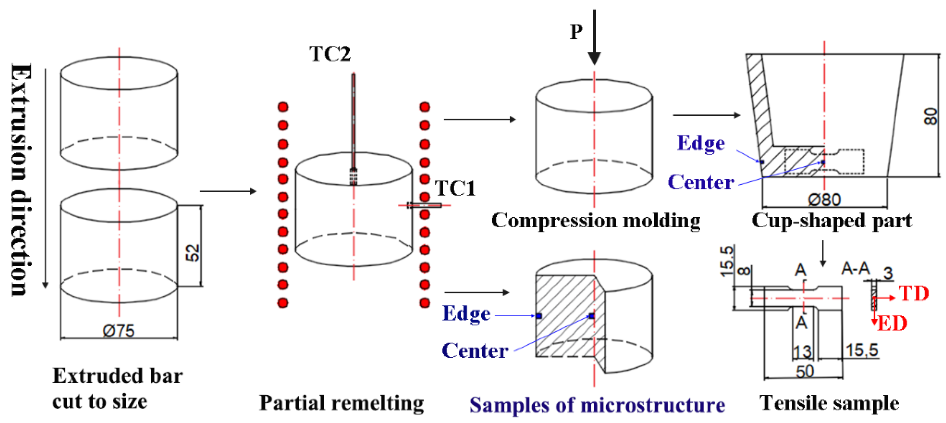
2. Experimental Procedure

As-extruded 7075-T6 aluminium alloys were supplied in 75 mm round bars as starting materials for the present investigation. The chemical compositions of the alloy are listed in Table 1.
Differential scanning calorimetry (DSC) was used to measure the thermal properties between solidus and liquidus using a NETZSCH DSC 404 F3 instrument. The test was performed under an atmosphere of pure argon at a flow rate of 10 mL/min with the heating rate of 5 °C/min. Liquidus and solidus temperatures as well as the variation in liquid fraction with temperature were determined using DSC results.
The cup-shaped parts for the compression test are illustrated in Figure 1. The hydraulic press used for compression has a maximum load capability of 20 kN with an average ram speed of 28 mm/s. During compression, the extruded bars were firstly cut into billets with 52 mm in length and 75 mm in diameter. Then, the billets were heated to 620 and 630 °C in an electric resistance furnace and the temperature was monitored by two thermocouples in the centre and the edge of the billets. Once the billet’s semi-solid heating was finished, it was transferred into a steel die cavity that was pre-heated to 300 °C for shaping, with a ram speed of 28 mm/s for 40 s of holding time to produce the final parts.
Samples used for microstructural examination of semi-solid billets were obtained by quenching the semi-solid billets in cold water after reheating to 620 °C and 630 °C for 10, 20 and 50 min. In order to examine the microstructural uniformity, the samples were sliced from the edge to the centre of as-extruded and partial re-melted billets along the extrusion direction. The samples of cup-shaped parts were taken from the edge and the centre of parts according to the method shown in Figure 1. These as-received and as-processed samples were mounted and mechanically polished following a standard procedure. Keller’s reagent was used as the etchant. Metallographic examination was completed using optical microscopy (OM), scanning electron microscopy (SEM, ZEISS SUPRA 35) equipped with energy-dispersive X-ray spectroscopy (EDS), and electron backscattered diffraction (EBSD). The samples used for EBSD examination were electrochemically polished in a solution of 10% HClO4 and 90% absolute ethanol at −20 °C at 20 V for 25 s to produce a strain-free surface. The EBSD maps were obtained using a ZEISS SUPRA 35 scanning electron microscope with an HKL OIM system operated with an accelerating voltage of 20 keV and steps of 0.8 μm.
To investigate the tensile behaviour of shaped parts, samples with gauge section of 13 mm × 8 mm × 3 mm (L × W × H) were cut from the cup-shaped parts, and a series of direct tensile tests was conducted using a Zwick Z100/SN3A universal testing machine. Room temperature tension tests were performed at a strain rate of 1 × 10⁻³ s−1.

3. Results

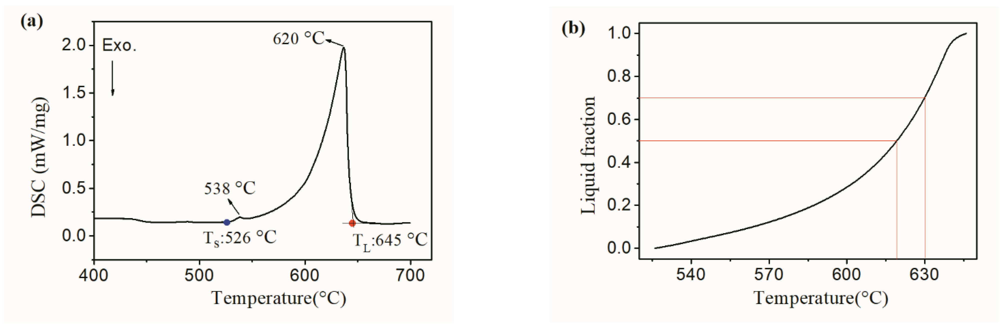
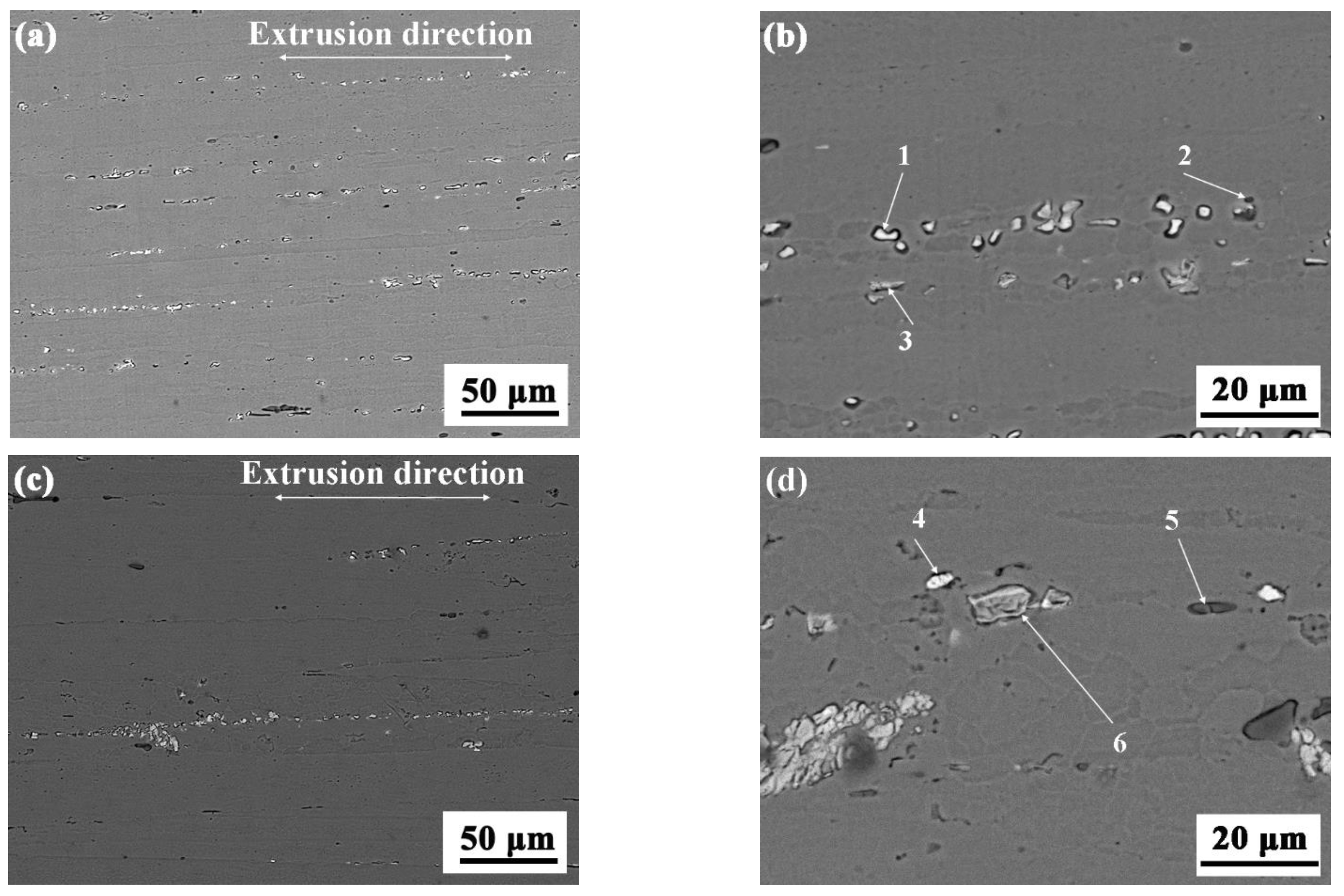
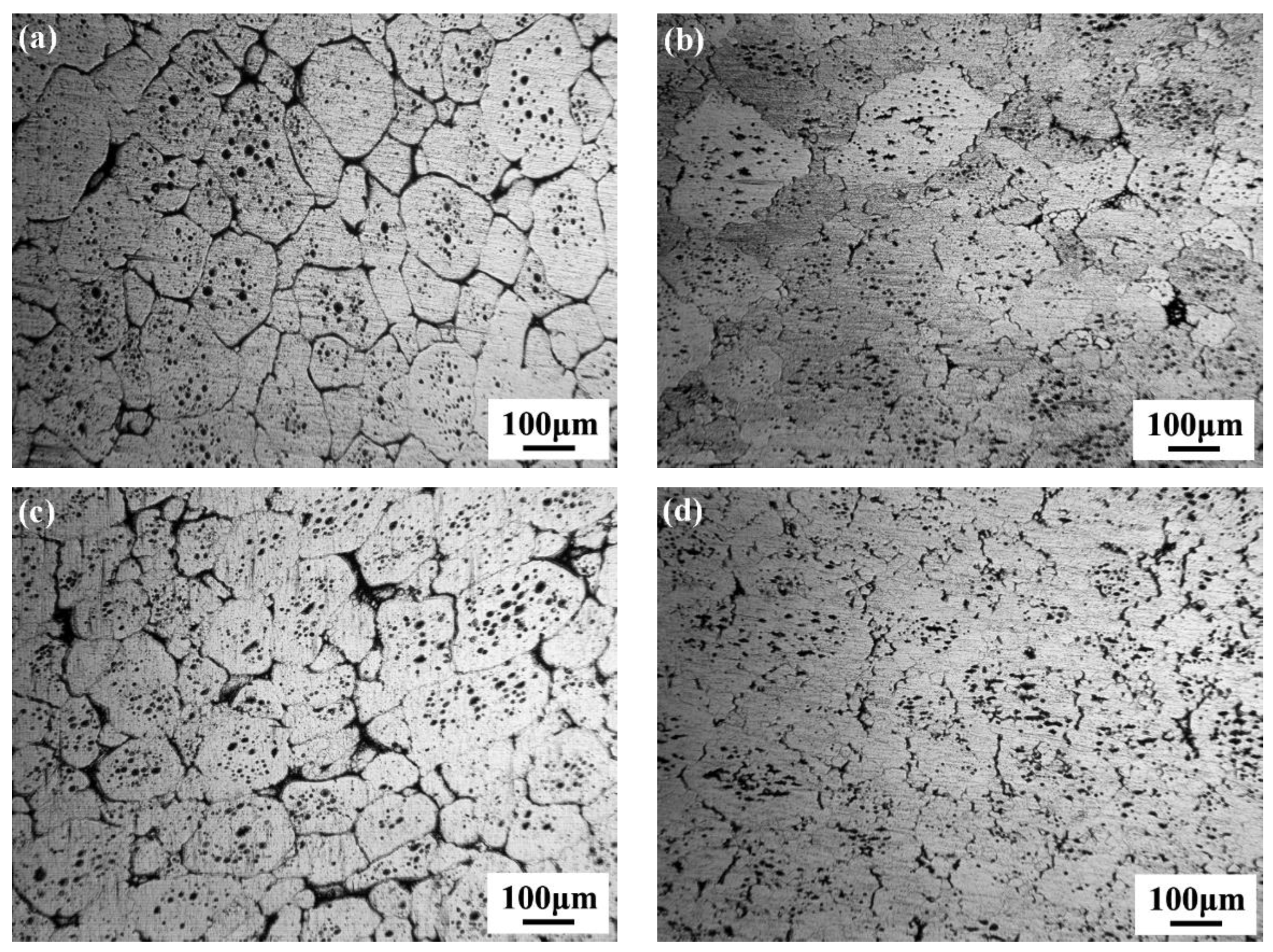
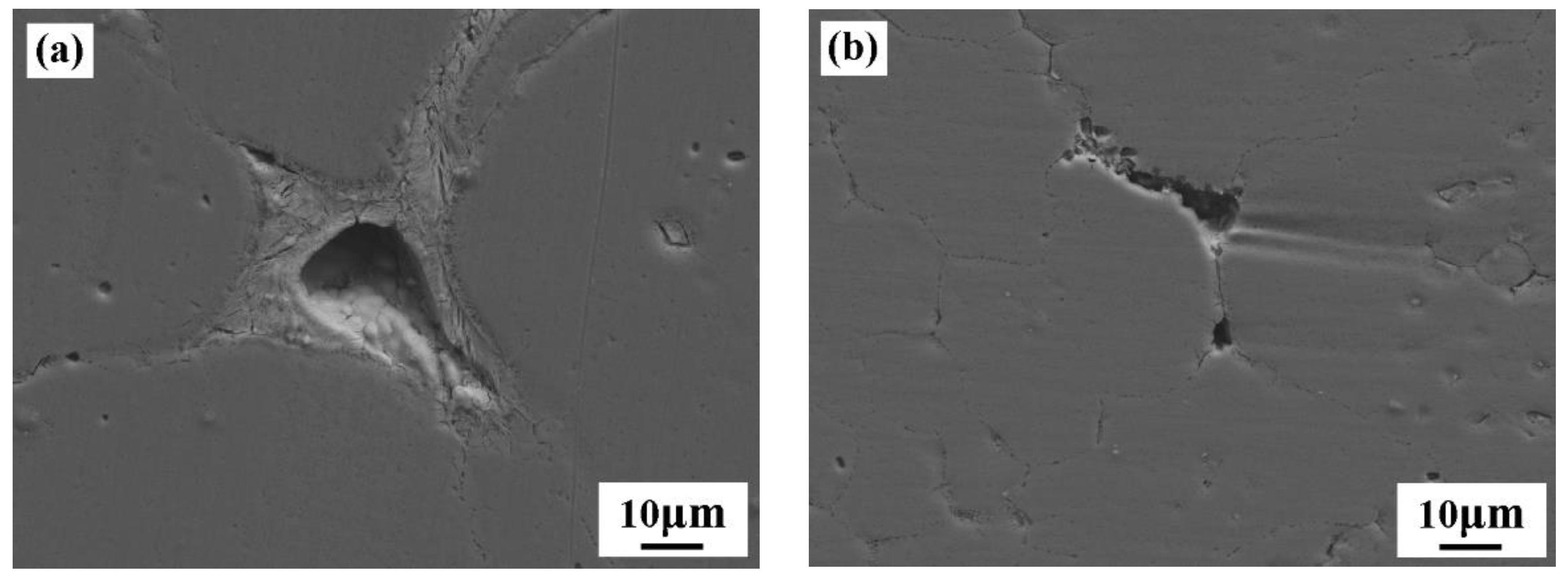
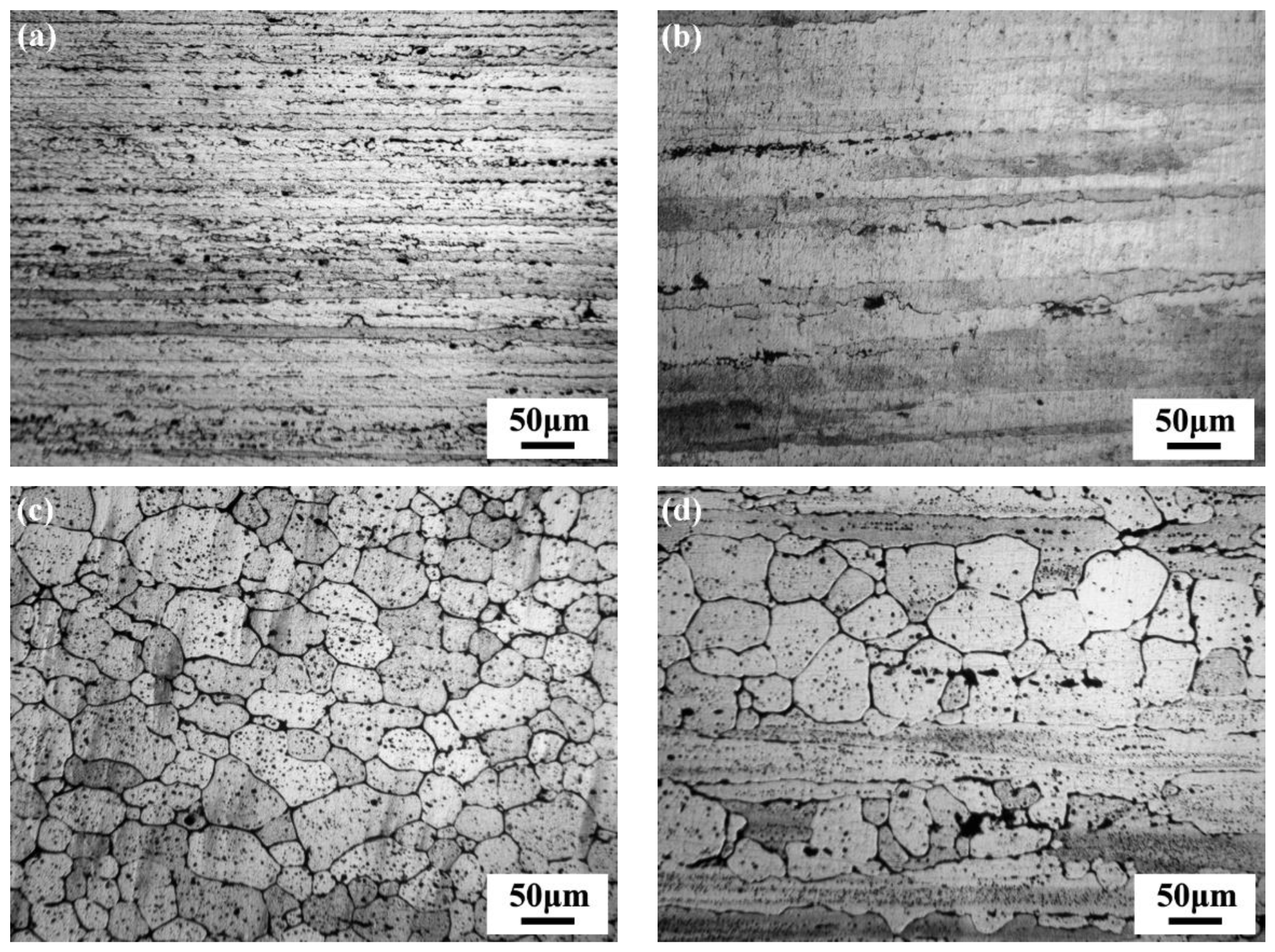
3.1. Thermal Property and Microstructure of 7075 Aluminium Alloy via Partial Re-Melting

Figure 2 shows the DSC result of as-extruded sample from room temperature to 700 °C. Two endothermic peaks were detected at the temperatures of 538 °C and 620 °C, respectively. The semi-solid temperature interval for the as-extruded 7075 Al alloy was determined to be 526–645 °C. Through integration of the DSC curve, the variance of liquid fraction with temperatures was calculated based on enthalpy measurement using the Scheil assumption. The liquid fractions of 0.50 and 0.70 of the semi-solid alloys corresponded to 619 and 630 °C between solidus and liquidus temperatures, respectively.
Microstructures of the as-extruded 7075 Al bars along the extrusion direction (ED) are shown in Figure 3, and EDS results (at.%) of secondary phases in the as-extruded 7075 aluminium alloy marked in Figure 3 are listed in Table 2. The microstructure of the alloy consisted of deformed and elongated α-Al grains with coarse intermetallic particles aligned in the ED. It should be noted that a wider range of elongated α-Al microstructures and coarser intermetallic particles could be found in the centre of as-extruded rods comparing with those at the edge of the rod. The 7075 alloy usually included fine strengthening precipitates, dispersoid particles and constituent particles based on the study by Chayong [24] and B. Binesh [25]. Based on the EDS results shown in Table 2, the light white phase marked as points 1 and 4 could be Al3MgZn2 and the black particles marked as points 2 and 5 could be Al5FeSi or Al8Fe2Si due to some fraction of Fe and Si in them. The light grey phase marked as points 3 and 6 could be Al7Cu2Fe. In addition, Zn, Cu and Mg in 7075 alloy could form precipitates including Al2CuMg and MgZn2, which could only be observed by transmission electron microscope (TEM) technique due to their few dimensions in nanometres.
Figure 4 shows the microstructure of 7075 aluminium alloy in the semi-solid state after isothermal holding at 620 °C and 630 °C for 50 min. The alloy through partial re-melting formed non-dendritic solid α-Al grains and intra-granular liquid droplets, as well as both secondary solidification grains and several porosities located in inter-granular regions. Combining with the microstructure shown in Figure 3, the elongated α-Al grains in as-extruded billets were transferred into non-dendritic solid grains in semi-solid feedstock, which can be attributes to recrystallisation behaviour during reheating [26]. According to the statistical results shown in Table 3, the average grain size of α-Al grains in the semi-solid feedstock was controlled between 101 μm and 121 μm with optimal combination of shape factor ranging from 0.58 to 0.70. These solid grains in semi-solid alloy were almost near-equiaxed, which was necessary to obtain thixotropic properties. Meanwhile, the solid grains of the sample at the edge of the feedstock had a slightly bigger and higher shape factor than those of the sample located in the centre comparatively, and the higher holding temperature in the semi-solid state resulted in a bigger grain size and higher shape factor value for α-Al grains in the semi-solid feedstock.

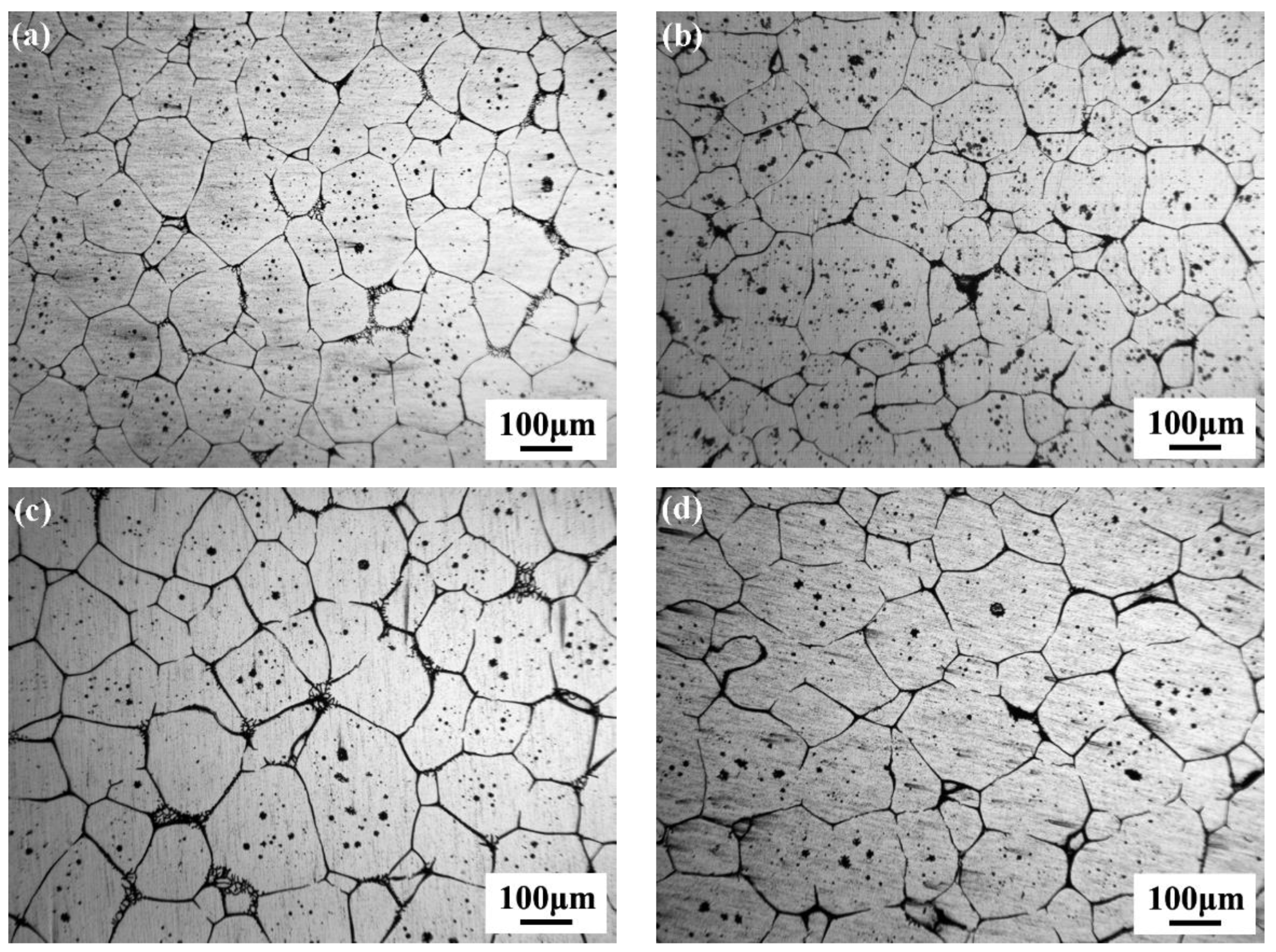
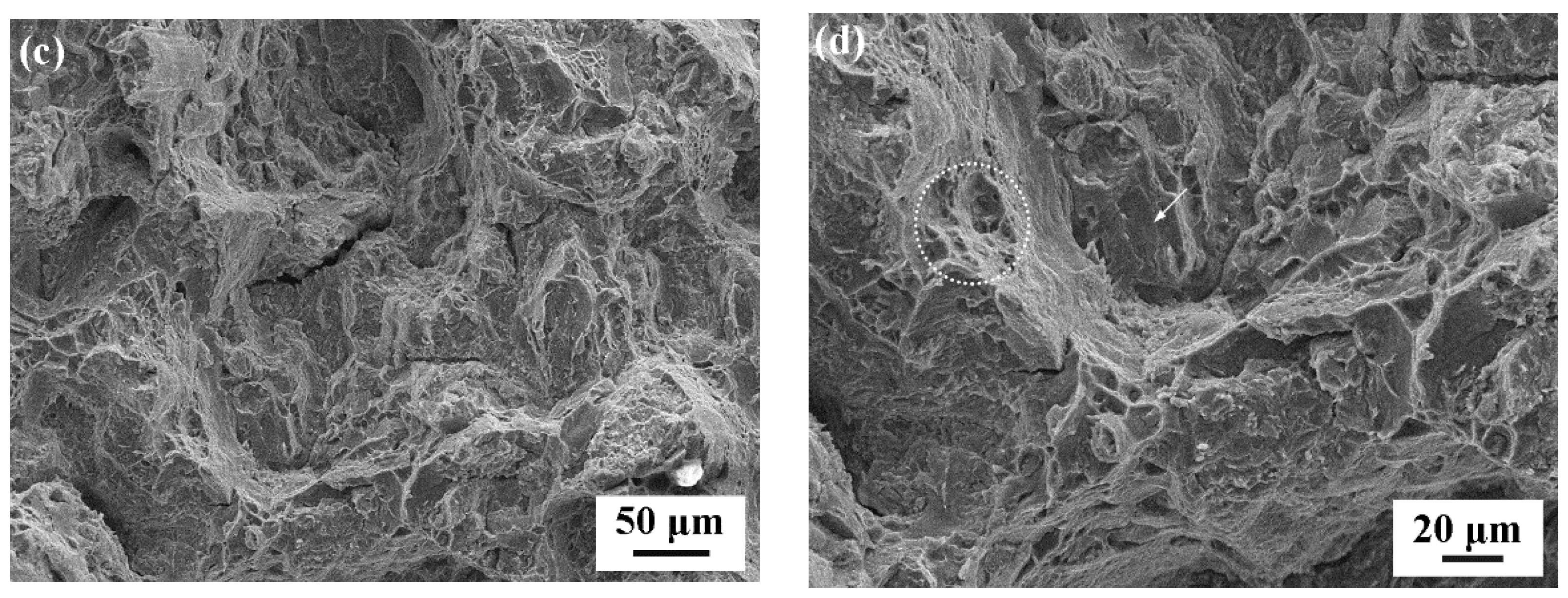
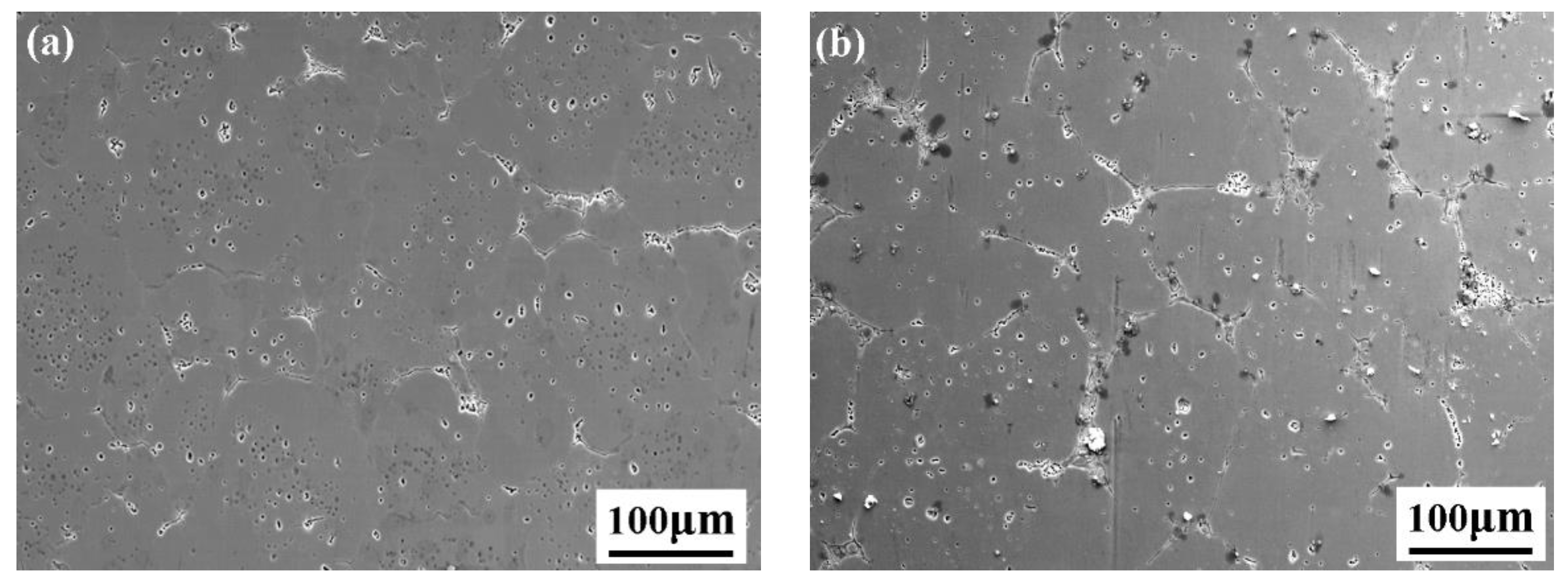
3.2. Microstructure and Tensile Properties of the Cup-Shaped Parts by SSM

Figure 5 shows the microstructure of samples from the cup-shaped parts. The microstructure of the samples located in the centre of the cup-shaped parts manifests as irregular deformed α-Al grains with thin inter-granular regions in Figure 5b,d, differing from the near-equiaxed morphology of solid grains in semi-solid feedstock. Whereas the α-Al grains in samples located at the edge of the parts almost maintain near-equiaxed morphology in Figure 5a,c. In addition, some refined grains that are much smaller than the initially solid grains in semi-solid feedstock can be observed in Figure 5d. It is worth noting that the inter-granular structure includes refined solidification microstructure and some porosities. The sample located at the edge of the cup-shaped part has more inter-granular refined grains than the sample located in the centre, and these refined grains were mainly formed during secondary solidification of residual liquid in semi-solid alloys. The distribution difference of secondary solidification microstructure suggests the transfer of residual liquid in semi-solid feedstock during SSM, leading to the microstructural segregation.
Figure 6 shows enlarged SEM images of the inter-granular regions in samples of cup-shaped parts produced at 620 °C. For the sample located at the edge of the cup-shaped part, coupled laminar eutectic phases solidify on α-Al grains, which is a common phenomenon in the case of hypoeutectic Al-Zn alloys [5]. Porosity is located in the centre of the inter-granular regions with a rough surface morphology, exhibiting secondary solidification fine grains on this surface. In contrast, the sample located in the centre of the cup-shaped part has little eutectic structure, with deformed porosities in the inter-granular regions, leading to thin inter-granular layers.
The mechanical properties of tensile samples produced by semi-solid compression are listed in Table 4, in which 0.2% proof stresses were determined from load-elongation curves. Both samples produced at 620 °C and 630 °C exhibit elongation of over 9% and tensile strength of over 250 MPa. Compared with the part produced at 620 °C, the part produced at 630 °C has higher tensile strength and larger elongation. Furthermore, the mechanical properties of the cup-shaped parts via SSM may be enhanced by heat treatments, and a study reported that the average tensile strength of a part through both thixo-extrusion and heat treatment can reach 485.49 MPa, and the average elongation to failure can be 5.49% [22].
According to the fracture morphology shown in Figure 7, both samples are characterised as mixed fractures with ductile and brittle qualities. There are obvious cleavage facets marked with an arrow and small ductile dimples marked with a circle on the tensile fracture, and a crack appears and expands along initial grain boundaries due to local stress concentrations at grain boundaries under applied stress. Comparatively, more fine ductile dimples can be observed on the fracture of sample produced at 630 °C. An inter-granular crack can also be observed on fracture surfaces in both samples, which can be associated with inter-granular porosities and a brittle eutectic microstructure.
In order to identify the microstructure of deformed samples, EBSD results shown in Figure 8 manifest the deformed grains with zigzag grain boundaries marked as a black line and the amount of sub-grain boundaries in initial semi-solid grains marked as a white line, in which the unidentified structure is mainly regarded as inter-granular defects. Obviously, some fine grains and a certain amount of sub-grains occur in the deformed samples, and these sub-grains between low grain boundaries maintain a similar crystallisation orientation, suggesting the origination of sub-grains from previous solid grains in semi-solid feedstock via plastic deformation. Compared with the microstructure of samples produced at 620 °C, samples produced at 630 °C have more low angle grain boundaries and high angle grain boundaries, which separate previous larger grains and reduce the overall area of grain boundaries.
Correlated misorientations display the angle distribution of the grain boundaries, and the theoretical curve represents what one would expect from a random set of orientations. The sample produced at 620 °C causes much more fraction of low angle grain boundaries than that in the sample produced at 630 °C. In addition, the difference between uncorrelated misorientation and the theoretical curve arises due to the strong texture and a large specific fraction of low-angle boundaries present in the sample produced at 620 °C. The ductility in samples is considerably promoted due to refined grains identified as sub-grain boundaries.

4. Discussion

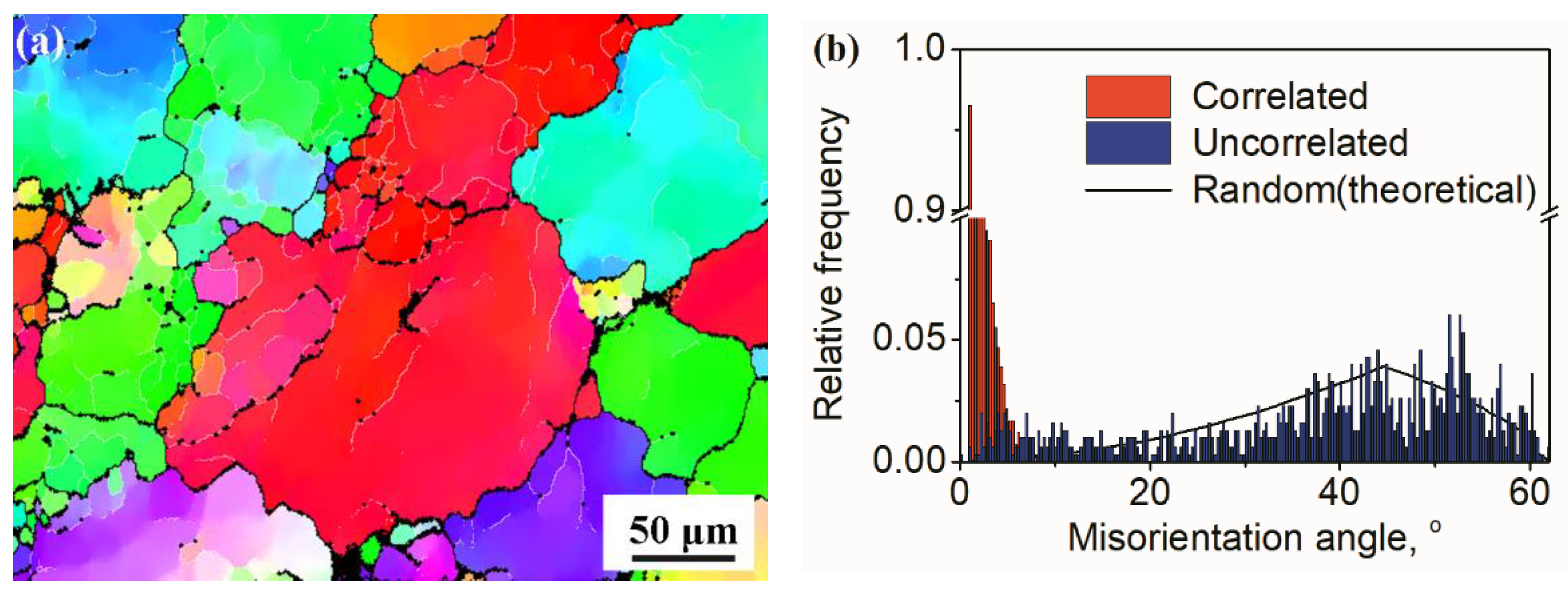
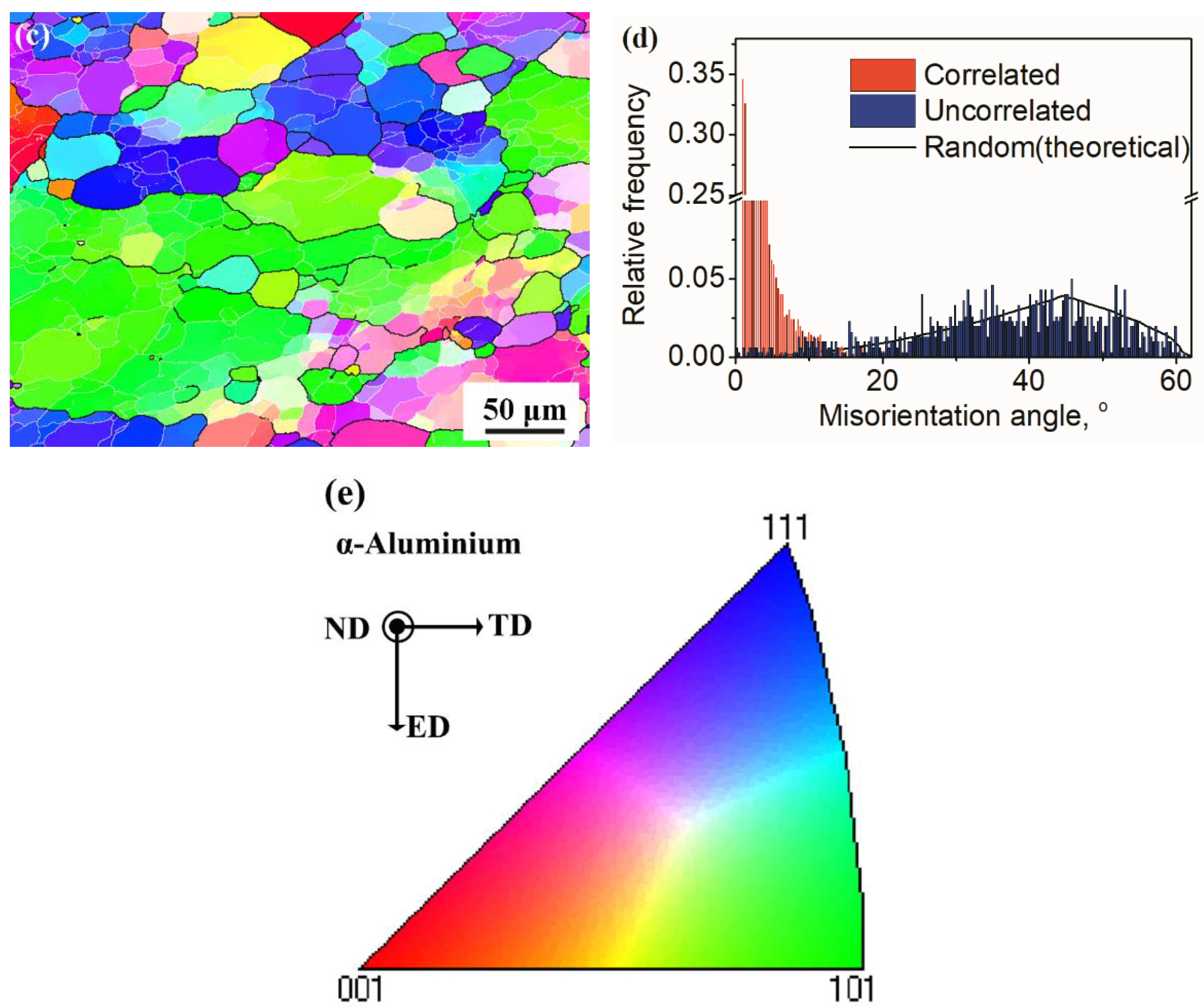
4.1. Microstructural Evolution during Semi-Solid Compression

The semi-solid alloys used for SSM are a mixture of non-dendritic solid particles and liquid metal surrounding these solid particles, which can be prepared by partial re-melting or partial solidification to the semi-solid state. In this investigation, the direct partial re-melting method was used to prepare semi-solid feedstock using as-extruded rods as initial material. The microstructure of as-extruded billets consists of elongated α-Al grain structure with a band distribution of coarse intermetallic particles along the ED, and near-equiaxed grains can be obtained at last via partial re-melting to the semi-solid state (Figure 3 and Figure 4). In the process of partial re-melting, it has been proven that the deformed microstructure in initial solid billets changes into equiaxed grains in the semi-solid state by recrystallisation, coarsening, spheroidisation and growth [1,27].
The microstructure of semi-solid feedstock depends on the recrystallisation behaviour of pre-deformation billets to some extent [14]. In order to refine the grains in semi-solid alloys, severe plastic deformation technology is usually used in pre-deformation billets to promote recrystallisation in partial re-melting [28,29,30]. However, the microstructure of large-diameter billets has a somewhat non-uniform distribution [31]; the deformation microstructure in the centre of the as-extruded bars exhibits a wider fibrous structure and coarser intermetallic particles in comparison with those of samples located at the edge of the bars in this investigation. However, the microstructure of the feedstock in the semi-solid state shown in Figure 5 has a relatively uniform distribution, with near-equiaxed grains in semi-solid feedstock via a relative retention time at semi-solid temperatures at last. Our previous study pointed out that optimal pre-deformation processing is suitable for achievement of solid grains with an excellent combination of grain size and shape factor for semi-solid feedstock [14].
Uniform microstructural components promote more uniform deformation and ultimately delay failure. Generally, induction heating is used in semi-solid metal processing in industry [32], which can reduce the temperature gradient in the billet and obtain a globular microstructure with uniform distribution. This investigation adopted electrical resistance heating to partially re-melt billets; there was a relative high temperature gradient in the billet. In order to examine the microstructural evolution of the non-uniform microstructure in pre-deformation billets during the partial re-melting process, a partial re-melting experiment was conducted at 630 °C, as shown in Figure 9. The recrystallisation grains occur on the boundaries of elongated α-Al grain concentrated with coarser intermetallic particles; fine grains can be found at these boundaries for samples holding for 10 min according to Figure 9a,b,d. For the sample located at the edge of the feedstock, the non-dendritic microstructure comes into being entirely at 620 °C (Figure 9c). Because of the wide elongated structure for the samples in the centre of the billet, only a portion of the recrystallisation grains transform into equiaxed grains and grow greatly, obtaining a mixture of equiaxed grains and coarsening grains with a banded structure as shown in Figure 9d. These banded structures are eventually separated into non-dendritic morphology by recrystallisation through the melt penetration to grain boundaries in the semi-solid state.
It is clear from Figure 9 that the solid grains of the alloy from the sample located at the centre of the semi-solid feedstock are much larger than those from the sample located at the edge of the semi-solid feedstock when they are held at 630 °C for 20 min. However, the solid grains of the sample at the edge of the prepared semi-solid feedstock have a bigger size than those at the centre in Figure 6. This suggests that the solid grains grow much faster when located at the edge of the semi-solid feedstock during the whole holding period.
It has been known that the growth and coarsening of the solid grains in the semi-solid alloy are under the control of coalescence and Ostwald ripening. Ostwald ripening is the dominant mechanism at high liquid volume fractions and it is in favour of the spheroidisation of solid grains [14], while the coalescence mechanism is more effective in grain growth, but has a minor effect on the spheroidisation process [33,34]. The liquid fraction of the alloy in the semi-solid state was determined to be about 0.5 and 0.7 at 620 and 630 °C, correspondingly, so it can be deduced that the growth of solid grains is mainly attributed to the Ostwald ripening, which accompanies the spheroidisation of solid grains in the semi-solid alloy.
From the microstructural evolution of the sample located in the centre of the semi-solid feedstock during the isothermal treatment, the large initial grain size of non-dendritic grains results in a slow growth rate. On the other hand, the morphology of the remaining banded structure with large size changes into near-equiaxed grains finally, suggesting the separation of large grains into small grains during this partial re-melting. It is proposed that the residual melt in the semi-solid alloy penetrates into the solid grain boundaries, accompanying a certain amount of energy consumption. In contrast, the non-dendritic grains of the sample located at the edge of the semi-solid feedstock consume energy by diffusion of the solid material from regions with high curvature to low curvature points, promoting the spheroidisation of solid grains [35]. Therefore, the shape factor of solid grains in the sample located at the edge of the semi-solid feedstock is higher than that of solid grains in the sample located at the centre, as shown in Table 3. Although the large strain difference between the edge and the centre of the billets causes varying deformed microstructures, a reasonable re-melting process is also effective for the achievement of a uniform non-dendritic microstructure in the semi-solid feedstock.

4.2. Deformation Mechanism

Figure 5 and Figure 8 manifest the microstructural characteristics including the solid grains and grain boundary structures after the deformation of solid grains in semi-solid alloys. The sub-grains in the samples produced at 630 °C have very uniform distribution of structural and compositional features. It was proposed that the solid grains in semi-solid alloys can plastically deform by pile-up and the accumulation of dislocation; at the same time, the plastic processing can also feed the shrinkage at the last stage of the SSM.
On the other hand, the microstructure in inter-granular regions is accompanied by solidification defects. Since 7075 aluminium alloy has a long solidification range and limited eutectic content, traditional casting methods usually result in porosity and solidification cracking [5]. It is known that porosity formation is associated with the lack of liquid feeding in the mushy zone, and the solidification cracking often happens due to a lack of liquid feeding at a high fraction of solids and when tensile or shear deformation is transmitted through the partially coherent mushy zone. Obviously, sufficient liquid feeding near the end of solidification is vital to avoid these solidification defects [36], and grain refinement has long been used to improve hot-tearing resistance during direct chill billet casting.
In the final stage of semi-solid compression, the solidification should be controlled precisely to adjust the inter-granular liquid feeding, which usually leads to inter-granular defects such as porosity and cracks due to the mass transfer of residual liquid in the semi-solid alloy [4]. Semi-solid metal forming can be divided into the die filling process and pressure intensification of semi-solid alloys [37]. The intensification stage during SSM aims to transport further material into the die cavity to compensate for the subsequent solidification shrinkage and dilatant shear bands. It has been believed that the pressure drop in the semi-solid state is associated with solidification shrinkage and shearing dilatancy [38]. Compared with traditional casting processing, the preparation of semi-solid feedstock promotes the formation of globular grains, and equiaxed or non-dendritic morphology of solid grains in semi-solid alloy can decrease the pressure drop in solidification channels significantly [11], subsequently enhancing the feedability in the last stage of solidification.
The semi-solid feedstock has a relatively uniform microstructure, but the microstructure in the cup-shaped parts varies greatly during semi-solid compression. For the cup-shaped part produced using semi-solid feedstock via being partially re-melted at 620 °C, the liquid is prone to being transferred from the centre to the edge of the cup-shaped parts, and the amount of eutectic phase located in the centre region decreases with narrow inter-granular regions, as shown in Figure 5 and Figure 9. The phenomenon can be attributed to the decreased liquid fraction. On the one hand, the semi-solid compression was conducted in non-isothermal conditions; the solid fraction of the semi-solid alloy increases with the decrease in the temperature of the semi-solid feedstock. On the other hand, the solid fraction of the semi-solid feedstock at 620 °C is roughly at a fraction of 50%, which corresponds to the critical solid fraction for the occurrence of liquid segregation. As a result, the residual liquid in the semi-solid feedstock is prone to transferring a long distance from the centre to the edge of the parts under compression [4], resulting in a decrease of inter-granular liquid for the sample located in the centre of the feedstock, and thus inter-granular porosities in the shaped parts are easily formed. In contrast, the initially equiaxed grains change into elongation deformed grains and cause sub-grain boundaries, and less liquid segregation occurs in the parts produced at 630 °C. In fact, the porosity in the sample located at the edge of the part is much larger than that in the sample located at the centre of the part based on the results in Figure 6.
Besides the variance of amount in eutectic microstructures in different locations, redistribution of residual liquid phase to compensate for the deformation can be hindered by the liquid channels and dense packing of the grain structure [16]. From Figure 10, the amount of inter-granular microstructure of the tensile sample from the part produced at 630 °C is much more than that at 620 °C, and the distribution of the inter-granular phase is more uniform for the sample produced at 630 °C. This phenomenon may be associated with little liquid segregation happening in parts produced by semi-solid compression at 630 °C, and enough liquid phase ensures that there is little pressure drop in solidification channels and guarantees the penetration of liquid into grain boundaries, resulting in a high integrity microstructure. What is more, the occurrence of a great number of sub-grain or grain boundaries can be caused by the penetration of liquid into grain boundaries.
Therefore, it is believed that both refined solid grains and residual liquid phase hinder the liquid segregation in semi-solid deformation, which reduces the pressure drop in the solidification channel and thus feeds the inter-granular solidification. In addition, the plastic deformation of initial solid grains induces many sub-grain boundaries, which can not only hamper the liquid segregation but also refine the initial grains. Subsequently, there is less inter-granular porosity in the microstructure. The experimental evidence includes the finding that the tensile sample produced at 630 °C has higher tensile strength and elongation. Similar experimental evidence also verifies that the 7075 alloy can achieve high integrity structure and high mechanical properties through thixo-extrusion under optimised processing conditions and mould geometry [22].

5. Conclusions

Inter-granular flow and intra-granular deformation occur simultaneously during semi-solid compression. Solid grain deformation can accommodate the feedability for the inter-granular liquid at the last stage of solidification by decreasing the pressure drop, which can improve the integrity of shaped parts.
Intra-granular deformation changes the morphology of initial solid grains in the semi-solid state and induces sub-grain boundaries in the initially formed grains, which can be attributed to the pileup of dislocations. The formation of sub-grains decreases the size of inter-granular regions and provides grain refinement.
The increase of sub-grain boundaries also improves the structural and compositional uniformity, which results in an improvement in elongation of shaped parts, which is featured by a mixture of ductile dimples and cleavage facets on the fractured surface.

Author Contributions

Conceptualisation, K.W. and F.L.; Draft, Methodology, Investigation, and Editing, K.W., S.H. and R.L.; Experiments and Analysis, R.L., T.W., T.G. and W.X. All authors have read and agreed to the published version of the manuscript.

Funding

This research was funded by the funds of the State Key Laboratory of Solidification Processing in NPU (Grant No. SKLSP201910), the National Natural Science Foundation of China (Grant No. 51974050), and the Chongqing Technology Innovation and Application Special Program (Grant No. cstc2020jscx-msxmX0203).

Institutional Review Board Statement

Not applicable.

Informed Consent Statement

Not applicable.

Data Availability Statement

Not applicable.

Acknowledgments

The advice from Shouxun Ji from Brunel Centre for Advanced Solidification Technology (BCAST), Brunel University, London, UK, for the study is gratefully acknowledged. We would like to thank Yang ZHOU from Analytical and Testing centre of Chongqing University for her assistance with microstructural analysis.

Conflicts of Interest

The authors declare that they have no known competing financial interests or personal relationships that could have appeared to influence the work reported in this paper.

References

  1. Flemings, M.C. Behavior of metal alloys in the semisolid state. Metall. Trans. A 1991, 22, 957–981. [Google Scholar] [CrossRef]
  2. Kirkwood, D.H. Semisolid metal processing. Int. Mater. Rev. 1994, 39, 173–189. [Google Scholar] [CrossRef]
  3. Wang, S. Atomic Structure Modeling of Multi-Principal-Element Alloys by the Principle of Maximum Entropy. Entropy 2013, 15, 5536–5548. [Google Scholar] [CrossRef]
  4. Li, N.; Mao, W.; Geng, X.; Zhang, R.; Yan, B. Microstructure, segregation and fracture behavior of 6061 aluminum alloy samples formed by semi-solid or traditional high pressure die casting. Mater. Today Commun. 2022, 31, 103418. [Google Scholar] [CrossRef]
  5. Pourgharibshahi, M.; Divandari, M.; Saghafian, H.; Timelli, G. Eutectic Nucleation in 7xxx Series Aluminum Alloys from a Non-classical Viewpoint. Metall. Mater. Trans. A 2020, 51, 4572–4583. [Google Scholar] [CrossRef]
  6. Rappaz, M.; Jacot, A.; Boettinger, W.J. Last-stage solidification of alloys: Theoretical model of dendrite-arm and grain coalescence. Metall. Mater. Trans. A 2003, 34, 467–479. [Google Scholar] [CrossRef]
  7. Kareh, K.M.; Lee, P.D.; Atwood, R.C.; Connolley, T.; Gourlay, C.M. Revealing the micromechanisms behind semi-solid metal deformation with time-resolved X-ray tomography. Nat. Commun. 2014, 5, 4464. [Google Scholar] [CrossRef]
  8. Eskin, D.G.; Suyitno; Katgerman, L. Mechanical properties in the semi-solid state and hot tearing of aluminium alloys. Prog. Mater. Sci. 2004, 49, 629–711. [Google Scholar] [CrossRef]
  9. Zabler, S.; Ershov, A.; Rack, A.; Garcia-Moreno, F.; Baumbach, T.; Banhart, J. Particle and liquid motion in semi-solid aluminium alloys: A quantitative in situ microradioscopy study. Acta Mater. 2013, 61, 1244–1253. [Google Scholar] [CrossRef]
  10. Meylan, B.; Terzi, S.; Gourlay, C.M.; Dahle, A.K. Dilatancy and rheology at 0–60% solid during equiaxed solidification. Acta Mater. 2011, 59, 3091–3101. [Google Scholar] [CrossRef]
  11. Sheykh-jaberi, F.; Cockcroft, S.L.; Maijer, D.M.; Phillion, A.B. Meso-scale modelling of semi-solid deformation in aluminum foundry alloys: Effects of feeding and microstructure on hot tearing susceptibility. J. Mater. Process. Technol. 2020, 279, 116551. [Google Scholar] [CrossRef]
  12. Otarawanna, S.; Laukli, H.I.; Gourlay, C.M.; Dahle, A.K. Feeding Mechanisms in High-Pressure Die Castings. Metall. Mater. Trans. A 2010, 41, 1836–1846. [Google Scholar] [CrossRef]
  13. Wang, Y.; Zhao, S.; Guo, Y.; Liu, K.; Zheng, S. Deformation Characteristics and Constitutive Equations for the Semi-Solid Isothermal Compression of Cold Radial Forged 6063 Aluminium Alloy. Materials 2021, 14, 194. [Google Scholar] [CrossRef]
  14. Song, Y.; Zhang, Z.; Wang, K.; Li, H.; Zhu, Z. Effects of Extrusion Processing on Microstructure of 7075Al Alloy in the Semi-solid State. J. Wuhan Univ. Technol. Mater. Sci. Ed. 2019, 34, 1433–1443. [Google Scholar] [CrossRef]
  15. Binesh, B.; Aghaie-Khafri, M. Microstructure and Properties of Semi-Solid Aluminum Alloys: A Literature Review. Metals 2018, 8, 181. [Google Scholar] [CrossRef] [Green Version]
  16. Sistaninia, M.; Phillion, A.B.; Drezet, J.-M.; Rappaz, M. Simulation of Semi-Solid Material Mechanical Behavior Using a Combined Discrete/Finite Element Method. Metall. Mater. Trans. A 2011, 42, 239–248. [Google Scholar] [CrossRef] [Green Version]
  17. Zhou, B.; Lu, S.; Xu, K.; Xu, C.; Wang, Z.; Wang, B. Hot cracking tendency test and simulation of 7075 semi-solid aluminium alloy. Trans. Nonferrous Met. Soc. China 2020, 30, 318–332. [Google Scholar] [CrossRef]
  18. Subroto, T.; Eskin, D.G.; Miroux, A.; Ellingsen, K.; M’Hamdi, M.; Katgerman, L. Semi-solid Constitutive Parameters and Failure Behavior of a Cast AA7050 Alloy. Metall. Mater. Trans. A 2021, 52, 871–888. [Google Scholar] [CrossRef]
  19. Liu, Z.; Cui, G.; Wan, T.; Mao, W. Study on Formation of Microstructure in Rheo-Diecastings of Semi-Solid A380 Aluminum Alloy Slurry. Met. Mater. Int. 2021, 27, 2095–2105. [Google Scholar] [CrossRef]
  20. Jiang, J.; Liu, Y.; Xiao, G.; Wang, Y.; Xiao, X. Effects of plastic deformation of solid phase on mechanical properties and microstructure of wrought 5A06 aluminum alloy in directly semisolid thixoforging. J. Alloys Compd. 2020, 831, 154748. [Google Scholar] [CrossRef]
  21. Bhagavath, S.; Cai, B.; Atwood, R.; Li, M.; Ghaffari, B.; Lee, P.D.; Karagadde, S. Combined Deformation and Solidification-Driven Porosity Formation in Aluminum Alloys. Metall. Mater. Trans. A 2019, 50, 4891–4899. [Google Scholar] [CrossRef] [Green Version]
  22. Liu, J.; Cheng, Y.; Chan, S.W.N.; Sung, D. Microstructure and mechanical properties of 7075 aluminum alloy during complex thixoextrusion. Trans. Nonferrous Met. Soc. China 2020, 30, 3173–3182. [Google Scholar] [CrossRef]
  23. Hitchcock, M.; Wang, Y.; Fan, Z. Secondary solidification behaviour of the Al–Si–Mg alloy prepared by the rheo-diecasting process. Acta Mater. 2007, 55, 1589–1598. [Google Scholar] [CrossRef]
  24. Chayong, S.; Atkinson, H.V.; Kapranos, P. Multistep induction heating regimes for thixoforming 7075 aluminium alloy. Mater. Sci. Technol. 2004, 20, 490–496. [Google Scholar] [CrossRef]
  25. Binesh, B.; Aghaie-Khafri, M. RUE-based semi-solid processing: Microstructure evolution and effective parameters. Mater. Des. 2016, 95, 268–286. [Google Scholar] [CrossRef]
  26. Atkinson, H.V.; Burke, K.; Vaneetveld, G. Recrystallisation in the semi-solid state in 7075 aluminium alloy. Mater. Sci. Eng. A 2008, 490, 266–276. [Google Scholar] [CrossRef] [Green Version]
  27. Atkinson, H.V. Modelling the semisolid processing of metallic alloys. Prog. Mater. Sci. 2005, 50, 341–412. [Google Scholar] [CrossRef] [Green Version]
  28. Chenyang, Z.; Shengdun, Z.; Guanhai, Y.; Yongfei, W. Deformation behaviour and microstructures of semi-solid A356.2 alloy prepared by radial forging process during high solid fraction compression. Proc. Inst. Mech. Eng. B J. Eng. Manuf. 2017, 232, 487–498. [Google Scholar]
  29. Campo, K.N.; Zoqui, E.J. Thixoforming of an ECAPed Aluminum A356 Alloy: Microstructure Evolution, Rheological Behavior, and Mechanical Properties. Metall. Mater. Trans. A 2016, 47, 1792–1802. [Google Scholar] [CrossRef]
  30. Wang, K.; Zhang, Z.M.; Wen, H.; Xia, D.; Sun, W.J. Microstructural evolution of a fine-grained 7075Al alloy processed by friction stir process during partial remelting. Mater. Charact. 2016, 121, 1–8. [Google Scholar] [CrossRef]
  31. Wang, W.W.; Song, J.L.; Luo, S.J. Preparation of Large-Diameter Semi-Solid 7075 Aluminum Alloy Billets. Solid State Phenom. 2008, 141–143, 361–365. [Google Scholar] [CrossRef]
  32. Jiang, H.; Nguyen, T.H.; Prud’homme, M. Optimal control of induction heating for semi-solid aluminum alloy forming. J. Mater. Process. Technol. 2007, 189, 182–191. [Google Scholar] [CrossRef]
  33. Wang, T.; Yin, Z.M.; Sun, Q. Effect of homogenization treatment on microstructure and hot workability of high strength 7B04 aluminium alloy. Trans. Nonferrous Met. Soc. China 2007, 17, 335–339. [Google Scholar] [CrossRef]
  34. Fan, X.G.; Jiang, D.M.; Meng, Q.C.; Zhang, B.Y.; Wang, T. Evolution of eutectic structures in Al-Zn-Mg-Cu alloys during heat treatment. Trans. Nonferrous Met. Soc. China 2006, 16, 577–581. [Google Scholar] [CrossRef]
  35. Yan, G.; Zhao, S.; Ma, S.; Shou, H. Microstructural evolution of A356.2 alloy prepared by the SIMA process. Mater. Charact. 2012, 69, 45–51. [Google Scholar] [CrossRef]
  36. Agarwal, G.; Amirthalingam, M.; Moon, S.C.; Dippenaar, R.J.; Richardson, I.M.; Hermans, M.J.M. Experimental evidence of liquid feeding during solidification of a steel. Scr. Mater. 2018, 146, 105–109. [Google Scholar] [CrossRef]
  37. Jarfors, A.E.W.; Zhou, J.; Du, A.; Zheng, J.; Yu, G. On the Part Quality, Process Parameters and In-Die Pressures in Indirect Squeeze Casting. Technologies 2021, 9, 95. [Google Scholar] [CrossRef]
  38. Rappaz, M.; Drezet, J.M.; Mathier, V.; Vernède, S. Towards a Micro-Macro Model of Hot Tearing. Mater. Sci. Forum. 2006, 519–521, 1665–1674. [Google Scholar] [CrossRef] [Green Version]
Figure 1. Schematic of the semi-solid process to fabricate the cup-shaped part and samples, unit in mm.
Crystals 12 01119 g001
Figure 2. (a) DSC curve and (b) calculated curve of liquid fraction versus temperatures using the Scheil assumption for the 7075 aluminium alloy sample from 400 °C to 700 °C.
Crystals 12 01119 g002
Figure 3. The SEM backscattered electron images of the as-received 7075 aluminium alloy in ED plane for: (a,b) sample at the edge position of the as-extruded rod; (c,d) sample at the centre position of as-extruded bars.
Crystals 12 01119 g003
Figure 4. Semi-solid microstructure of 7075 aluminium alloy for 50 min at: (a) 620 °C located at the edge of billets; (b) 620 °C located in the centre of billets; (c) 630 °C located at the edge of billets; (d) 630 °C located in the centre of billets.
Crystals 12 01119 g004
Figure 5. Metallographic diagram of different positions of the deformed part prepared at different deforming temperatures: (a) located at the edge and holding at 620 °C; (b) located at the centre and holding at 620 °C; (c) located at the edge and holding at 630 °C; (d) located at the centre and holding at 630 °C.
Crystals 12 01119 g005
Figure 6. SEM images of inter-granular structure of samples of cup-shaped parts via semi-solid compressed at 620 °C: (a) sample located at the edge of the part; (b) sample located at the edge of the part.
Crystals 12 01119 g006
Figure 7. SEM micrographs of the tensile fracture for 7075 aluminium alloy produced by semi-solid compression at: (a,b) 620 °C; (c,d) 630 °C.
Crystals 12 01119 g007aCrystals 12 01119 g007b
Figure 8. EBSD micrographs and misorientation angle distribution for 7075 aluminium alloy samples produced at: (a,b) 620 °C; (c,d) 630 °C; and (e) stereographic triangle of IPF colour map.
Crystals 12 01119 g008aCrystals 12 01119 g008b
Figure 9. Microstructure of 7075 aluminium alloy after partial re-melting at 630 °C for different holding times: (a) 10 min at the edge; (b) 10 min at the centre; (c) 20 min at the edge; (d) 20 min at the centre.
Crystals 12 01119 g009
Figure 10. SEM photography of samples cut from the centre of the parts via semi-solid compression: (a) 620 °C; (b) 630 °C.
Crystals 12 01119 g010
Table 1. Chemical compositions of the experimental 7075 aluminium alloy obtained by OES (wt.%).
ZnMgCuCrSiFeMnTiAl
5.62.51.60.230.40.50.30.2Bal.
Table 2. EDS results (at.%) of secondary phases of as-extruded 7075 aluminium alloy marked in Figure 3.
AlZnCuMgFeSi
Point 179.831.7915.542.84--
Point 267.72.362.432.170.2225.12
Point 383.443.058.432.432.65-
Point 483.972.5210.292.690.53-
Point 567.431.60.732.060.0228.16
Point 643.752.6449.771.42.44-
Table 3. Statistical results of microstructure of semi-solid 7075 aluminium alloys.
Average Grain Sizes, μmAverage Shape Factors of Solid Grains
EdgeCentreEdgeCentre
620 °C106 ± 15101 ± 130.66 ± 0.220.58 ± 0.34
630 °C121 ± 18116 ± 90.70 ± 0.150.60 ± 0.21
Table 4. Tensile strength, elongation and 0.2% proof stress of tensile samples in the cup-shaped part via semi-solid compression.
0.2% Proof Stress, MPaTensile Strength, MPaElongation, %
620 °C172 ± 7268 ± 129 ± 2
630 °C199 ± 6307 ± 1111 ± 1
Publisher’s Note: MDPI stays neutral with regard to jurisdictional claims in published maps and institutional affiliations.

